F5 BIG-IP LTM 详解(工作原理 配置手册)
F5 BIG-IP LTM 详解(工作原理 配置手册)
Fowarding VS(Forwarding IP)
客户端
查询本地路由表
TMM
转发客户端请求
• 只能使用Fast L4 Profile • 按照连接处理,类似于路由器工作,但不完全一样,在Fast L4
Profile中开启Loose Initial和Loose Close之后更为接近路由工作模式 • 所有穿过Fowarding VS的连接都将产生连接表 • 没有Pool Member,转发完全取决于本地路由 • 可以使用基于4层的Rules
TM/OS
Host OS
Web 界面管理 健康检查 SNMP ……..
独立的管理机 管理CPU SCCP
TMM 0
BridgeLeabharlann SSL加解密HTTP压缩
PVA(Packet Velocity ASIC)
四层交换专用ASIC
万兆/千兆交换端口
Admin
Console
BIGIP 内部结构-Mecury平台16/36/69/89
VS和Rules
Rate Shaping TCP Express
SSL TrafficShield
Caching XML Web Accel 3rd Party
Compression OneConnect TCP Express
Microkernel
TCP Proxy
Client Server Side Side
HTTP_REQUEST HTTP_REQUEST_DATA
RTSP_REQUEST . . . .
TCP Proxy
Client Server Side Side
F5配置文档
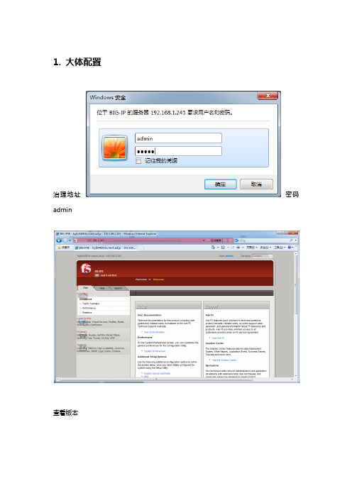
1.大体配置治理地址密码admin查看版本许可:更改治理配置检查日记2.HA配置计划组网方式(一种方式)选择F5 BIG-IP LTM以并行结构接入现有网络环境中,在对BIG-IP LTM进行VLAN划分、IP地址分派时,能够将BIG-IP LTM与所需进行负载均衡的效劳器处于相同VLAN中,所分派的IP地址与效劳器原有IP地址在同一网段内。
如以下图所示:这种方式的接入,F5 BIG-IP LTM与效劳器在同一网段下,所有配置的VS 地址与效劳器IP地址均在同一网段下,通过如此的配置使网络层次结构、数据流量的传输看起来加倍清楚,实施相对较为简单。
在这种方式下效劳器的默许网关一样会设置为BIG-IP LTM上对应的Self IP 或Floating IP,使客户端流量通过BIG-IP LTM负载均衡后直接抵达后端效劳器时,无需做任何源地址转换及路由选择,保留了客户端源地址,能够很容易的知足应用上一些特定要求。
HA部署方式(一种方式)两台F5 BIG-IP LTM间采纳Failover线缆监控设备心跳信息,数据同步信息与实际业务数据别离在单独的线路上传递,具体如以下图所示:如此部署的优势在于使BIG-IP LTM设备间心跳信息和数据信息在不同的通道传送,保证了数据独立性,同时数据信息和业务信息分开,保证了其平平稳固性,但增加了设备端口的利用数量。
建议在设备端口密度充沛的情形下利用此种部署结构。
VLAN计划在此连接模式下,建议BIG-IP上划分3个VLAN,别离为:Internal:用于连接后端的服务器,通常,我们采用100M端口连接后端服务器。
failover_vlan:主要用于两台BIG-IP之间的配置同步和Session同步。
通常情况下在端口数量足够的时候我们用一个单独的端口用于配置和Session同步。
如果在端口数量不足时,可不使用本VLAN而使用internal VLAN来进行配置和Session同步。
F5BIGIPLTM详解(工作原理配置手册)专题培训课件
Data
TMM
Syn Syn-Ack
Ack
• 正常情况下客户端连接和服务器端连接是1:1的关系 • TMM在第一次收到客户端Syn包时,并不建立连接表 • TMM的Syn Ack回应通过算法回应给客户端Syn,并期待客户端回应的值 • TMM对客户端ACK进行计算,确认是真实客户端,再和后台服务器建立连接 • 在84/88上可以实现硬件的Syn Cookie计算,其余的平台都是通过软件实现
SNAT地址和后台建立连接 • Standard VS的端口永远对外开放,无论后台是否有服务器在工作
Standard 模式下的攻击防护
• Standard VS模式具有天然的防攻击功能 • 在遇到Syn攻击的时候会导致系统的连接表过大 • 通过System-SYN Check Activation Threshold
查看TMM内存占用情况 • TMM分配的内存是准确的,Host内存显示在这里有一些偏差
VS Type详解
• Performance L4 • Standard VS • Fast HTTP • Forwarding VS
客户端 客户端 客户端
Performance L4
服务器端
TMM
服务器端 服务器端
I/O控制 • 所有的生产流量都通过TMM接收 • 一个CPU Core只能有一个TMM进程 • 在V9版本上,15/34/64/68都是单TMM运行 • 在V9版本上,16/36/69/89/84/88都是多TMM运行 • 在V10版本上,16/36/69/89/84/88都是多TMM运行 • Viprion只支持9.6和10.0版本,默认都是多TMM运行
比如ACK、RST等如果不在连接表中,则全部丢弃。 • 在Fast L4 profile打开Loose close和Loose Initial的时候对非Syn包也
F5+BIG-IP+LTM+负载均衡器配置指导书

F5 BIG-IP LTM负载均衡器配置指导书(v10)2022-04-27修订记录F5 BIG-IP LTM负载均衡器配置指导书目录第1章 F5 BIG-IP LTM简介 (1)1.1 负载均衡技术简介 (1)1.2 F5 BIG-IP LTM产品介绍 (1)1.3 产品面板简介 (3)1.4 配置方式 (5)1.5 基本概念 (6)第2章 BIG-IP LTM规划与配置准备工作 (8)2.1 BIG-IP LTM配置步骤 (8)2.2 组网规划 (9)2.2.1 规划准备要点 (9)2.2.2 组网图 (9)第3章基本配置 (11)3.1 通过LCD面板设置BIG-IP管理网口地址 (12)3.2 通过管理网口登录BIG-IP WebUI界面 (13)3.3 激活License (14)3.4 设置Platform (17)3.5 修改系统时钟 (19)3.6 配置网络 (20)3.6.1 划分VLAN (20)3.6.2 配置VLAN IP地址 (22)3.6.3 设置接口速率和双工类型 (24)3.6.4 配置静态路由 (24)3.6.5 配置Link Aggregation(可选) (26)第4章负载均衡业务配置 (27)4.1 节点配置 (27)4.2 配置负载均衡池 (28)4.3 配置虚拟服务器 (30)4.3.1 创建虚拟服务器 (30)4.3.2 将虚拟服务器和负载均衡器相关联和会话保持配置 (33)4.4 配置健康检查 (34)4.4.1 自定义节点状态监控 (35)4.4.2 监控与节点/负载均衡池相关联 (37)F5 BIG-IP LTM负载均衡器配置指导书4.4.3 检查系统状态 (39)4.5 配置SNAT (39)4.5.1 配置步骤 (39)4.5.2 验证SNAT配置 (42)第5章双机配置 (43)5.1 双机设置 (43)5.2 双机状态监控设置 (46)5.3 双机状态检查和配置同步 (48)第6章其他的组网方式 (49)6.1 单臂组网方式 (49)6.2 n-path组网方式 (50)F5 BIG-IP LTM负载均衡器配置指导书关键词:负载均衡池、虚拟服务器,节点、会话保持、监控、ECV、EAV、SNAT摘要:按照常见的配置步骤,本文对F5 BIG-IP LTM负载均衡器设备配置进行说明,并对负载均衡器的基本概念和F5设备使用过程中遇到的常见问题进行解答。
F5 BIG-IP LTM v10速查手册-new platform rv1

处理器、内存、存贮介质 处理器类型 处理器数量 CMP支持
内存 Compact Flash 硬盘
物理端口 Total Number of Ports for Use Included 10/100/1000 Mbps Ports Included 1 Gbps Fiber Ports Optional 1 Gbps Fiber Ports Optional 10 Gbps Ports
8 GB 8 GB 160 GB
88
22
32
8
16
4
32
8
8
2
40 Gbps 32M
368 Gbps 1M cps
355K cps 1.36M rps 3.2M rps
36 Gps
10 Gbps 8M
92 Gbps 250K cps
97K cps 340K rps 800K rps 10 Gbps
BIG-IP 8900 LTM
2 Gbps 4M
24 Gbps 115K cps
15K cps 65K rps 135K rps 2 Gbps
1 Gbps 4M
14 Gbps 60K cps
10K cps 40K rps 100K rps 1 Gbps
1 Gbps 4M
14 Gbps 60K cps
10K cps 40K rps 100K rps 1 Gbps
2 Gbps 4M
24 Gbps 115K cps
15K cps 65K rps 135K rps 2 Gbps
1 Gbps 4M
14 Gbps 60K cps
F5-BIG-IP-LTM-详解(工作原理-配置手册)

Web Accelerator Module(包括压缩) Application Security Module GTM的分配算法处理(包括GTM rules) Named域名解析 健康检查 日志管理 系统数据统计 SNMP数据输出 HA健康检查
BIGIP 内部结构-V9平台15/34/64/68
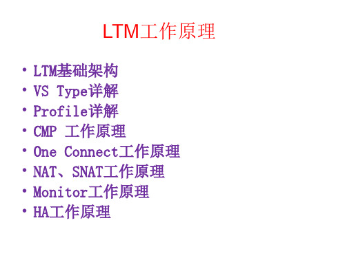
F5 BIG-IP LTM详解
北京先进数通信息技术有限公司 十二月 19
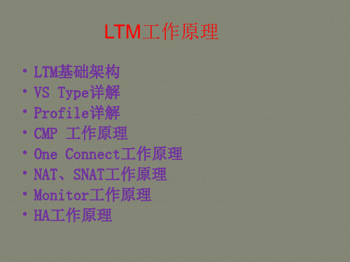
LTM工作原理
• LTM基础架构 • VS Type详解 • Profile详解 • CMP 工作原理 • One Connect工作原理 • NAT、SNAT工作原理 • Monitor工作原理 • HA工作原理
LTM基础架构
• Host在启动的时候限 定了内存分配的大小 ,在没有其他module 的情况下是384MB
• TMM进程启动后,将 自动获取余下的所有 物理内存
查看Host内存占用情况
• # physmem /查看物理内存大小 8387584
• b memory show /查看内存分配情况 MEMORY STATISTICS -| (Host) Total = 3.835GB Used = 3.590GB | (TMM) Total = 5.976GB Used = 93.22MB
F5 BIG-IP配置指导书

F5 BIG-IP负载均衡器配置指导书目录一、ISMG网络结构与IP地址规划 (3)二、配置BIGIP3400负载均衡设备 (4)2.1设置负载均衡器管理网口地址 (4)2.2登录BIGIP的WEB管理界面 (5)2.3激活License (5)2.4初始化设置 (7)2.4.1BIG-IP 1上的平台(Platform)通用属性设置 (7)2.4.2修改系统时间 (8)2.4.4重新启动bigip (9)2.5配置网络层 (9)2.5.1划分vlan (9)2.5.2定义IP地址 (11)2.5.3配置路由 (13)2.6配置双机设置(High Availability) (14)2.6.1配置Redundant Pair的IP地址 (14)2.6.2配置双机自动切换机制FailSafe配置 (16)2.7配置服务器负载均衡 (17)2.7.1配置Monitor (17)2.7.2配置Profile (18)2.7.3配置负载均衡Pool (19)2.7.5建立Virtual server,实现对服务器的负载均衡 (20)2.7.5设置SNAT (23)2.8两台BIGIP配置同步 (26)2.9备份配置 (26)三、系统运行状态检查及维护 (27)3.1检查系统日志信息: (27)3.2检查Node状态 (28)3.3查看流量信息 (29)3.4查看系统当前性能参数 (29)3.5密码的更改 (30)3.6添加“只读”权限的管理员帐号 (30)3.7如何查询设备的序列号: (31)3.8如何采集信息提供他人进行故障诊断 (31)3.8对某一Virtual Server用TCPDUMP命令无法抓到包如何处理? (32)一、网络结构与IP地址规划网络拓扑结构如下图所示:略相关的IP地址规划如下:注:以上的IP地址规划是测试环境的IP地址设置,需要根据现网环境中的IP地址规划进行修改。
注:以下接口连接表还没有更新,需要由现场工程师更新的。
F5BIG-IPLTM标准配置文档

F5BIG-IPLTM标准配置文档BIG-IP LTM 标准配置文档目录一、设备配置准备工作 (3)1.设备硬件环境准备 (3)2.工作站F5设备连接 (4)二、网络基础配置 (7)1.激活License (7)2.网络配置 (14)三、服务器负载均衡配置 (18)1.配置default_gateway_vs (18)2.针对服务建立相应VS (20)一、设备配置准备工作1.设备硬件环境准备1.BigIP 1500及随机器配置的电源线、Console线、网线等;2.工作站一台并且预装了下列软件工具:SSH工具软件如SecureCRT;SFTP工具软件如WinSCP;3.上网环境:需要上网激活F5设备;4.LTM实施完成后拓扑图:2.工作站F5设备连接1.将Console 线连接工作站COM 口和F5的console 口,网线连接工作站网口和F5的MGMT网口。
2.如果工作站使用“超级终端”,COM 口设置如下:如果工作站使用SecureCRT ,设置如下:3.F5的MGMT网口默认的IP地址为192.168.1.245/24,因此,配置工作站网口的地址为192.168.1.200/24,以便与F5设备连接;4.工作站上ssh工具如SecureCRT设置如下:二、网络基础配置1.激活License1.系统时间修改:使用超级终端或者SecureCRT登录F5 BIG-IP的console口,输入命令:[root@localhost:Active] config # date查看当前系统时间:如果系统时间正确,则不作修改,退出console;如果系统时间不正确,使用下面两条命令修改到正确的时间:[root@localhost:Active] config # date MMDDhhmmYYYY[root@localhost:Active] config # hwclock --systohc2.登录F5 BIG-IP LTM设备并输入key,获取dossior.do文件在工作站使用IE浏览器,输入https://192.168.1.245登录BIG-IP点击“是”确认证书。
F5详细配置手册
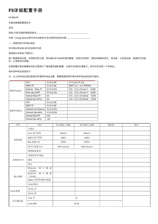
F5详细配置⼿册F5 BIG-IP负载均衡器配置指导书⽬录添加“只读”权限的管理员帐号.............................................................................................对某⼀Virtual Server⽤TCPDUMP命令⽆法抓到包如何处理............................................⼀、⽹络结构与IP地址规划本⼿册以移动W AP/彩信⽹关为例⽹络拓扑结构如下图所⽰:整个数据⽹络设备,采⽤两台防⽕墙、两台BIG-IP 3400负载均衡器、及两台交换机、⽹络设备都采⽤主、备设备,以实现设备、链路的冗余备份,以消除单点故障。
这⾥部署负载均衡器的⽬的主要是为了增加服务器的数量,以提升系统的处理能⼒。
但对外仍然是⼀个IP地址。
相关的IP地址规划如下:注:以上的IP地址规划是测试环境的IP地址设置,需要根据现⽹环境中的IP地址规划进⾏修改。
⼆、配置BIGIP3400负载均衡设备本章将主要描述BIGIP3400负载均衡设备的配置⽅法及配置内容。
旁路/直连的选择2.1.1路由/直连模式的介绍⽹络连接的物理结构如下结构:Ip规划说明:图中bigip为负载均衡交换机,bigip上⾯使⽤公开的ip地址,bigip下⾯同负载均衡的服务器使⽤不公开的ip地址。
但对外提供服务则使⽤公开的ip。
2.1.2旁路模式的介绍⽹络连接的物理结构如下结构:Ip规划说明:图中bigip为负载均衡交换机,bigip和负载均衡的服务器均使⽤公开的ip 地址。
2.1.3 路由/直连模式同旁路模式的⽐较(1)流量⾛向不⼀样;路由/直连模式的流量⾛向如下:如上图,bigip同客户端的流量在bigip的上联接⼝,bigip同服务器的流量在下⾯的接⼝。
旁路模式的流量⾛向如下:如上图,bigip⽆论同客户端还是同服务器的通讯流量均在bigip的⼀个接⼝上。
F5 LTM配置手册
5. 双机配置 1) 确认主、备 F5 运行在双机模式,点击 System->Platform 进行查看修改。 主 F5:
备 F5:
2) High Availability 配置 冗余模式:点击 System->High Availability,如下图:
第 11 页
Network Mirroring 配置, 主 F5:
的配置文件,根据需要选择),选择 Restore,即可进行恢复。
3) 配置文件上传、下载 同样在 System->Archives 中,选择 Upload 即可上传配置文件,上传配置文
件可用于后续的恢复。 若要下载配置文件,点击相应的配置文件,即可进行 Download 操作。
第 17 页
技术交流 仅供参考
二、 网络拓扑
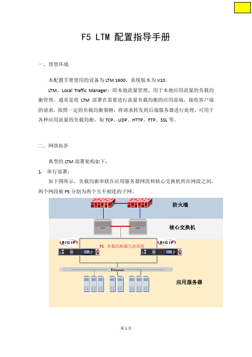
典型的 LTM 部署架构如下: 1. 串行部署:
如下图所示,负载均衡串联在应用服务器网段和核心交换机所在网段之间, 两个网段被 F5 分割为两个互不相连的子网。
防火墙
F5 负载均衡器冗余系统
核心交换机
Ethernet
应用服务器
第1页
2. 旁路部署: 如下图所示,负载均衡旁路接入网络,不需要对现有网络架构进行调整。物
3) 可以Copy Dossier文本或下载文件,登录到F5的激活页面: https:///license/dossier.jsp 将复制的Dossier文本粘贴进去,或上传文本文件,选择Next,获取到License 激活文件,将激活代码复制到F5的界面,从而激活设备。
第4页ห้องสมุดไป่ตู้
3. 系统基础配置 点击 System->Platform,配置管理地址、主机名、时区等;
最新F5 LTM配置文档资料

© F5 Networks
Pool配置
9
© F5 Networks
创建负载均衡Pool
在“Local Traffic→Pools”页面点击“create”按钮: ①、Name栏填写:(填一个英文名称) ②、Health Monitors栏:选择健康检查方式 ③、Load Balancing Method栏选择:Round Robin (这里选择的负载均衡方式是轮询,也可以选择其他方式) ④、New Members栏:先选择New Address,再添加 服务器的IP地址,如:192.168.1.11、192.168.1.12以及它 们的端口80
10
© F5 Networks
常用Load Balancing Method选择
• Round Robin 该模式为缺省负载均衡法。Round Robin模式将每个新连接请求一致 地传递到下一个服务器,最终将连接平均分配到负载均衡的一组设备上。Round Robin 模式在大多数配置中运行良好,特别是在负载均衡设备的处理速度和内存基本相同的情 况下。 • Ratio (member)和Ratio (node) LTM系统按照您所设定的比率权重在设备中分配连 接,每个设备随时间变化接收的连接的数量与您为每个设备定义的比率权重成一定比例。 这些属于静态负载均衡法 • Least Connections (member)和Least Connections (node) Least Connections方法 相对比较简单,因为采用此方法,LTM系统可以将新连接传递到当前连接数量最少的节 点。Least Connections方法的最佳工作环境为您正在平衡的服务器或其它设备具有相近 的功能。 • Observed (member)和Observed (node) Observed方法结合使用了在Least Connections和Fastest模式下使用的逻辑。采用Observed方法,可以结合当前连接的数 量和响应时间对节点进行排序。那些能够很好地平衡最少连接和最短响应时间的节点接 收连接的比例更大。Observed模式在任何环境下运行良好,尤其适用于节点性能变化较 大的环境下。
f5 bigip ltm 详解(工作原理 配置手册)教学内容

• TMM只是负责客户端连接的分配和转发,不改变TCP连接中的任何参数 • 客户端和服务器自行协商TCP传输参数 • 在34/64/68平台上Performance L4可以有PVA加入实现硬件加速 • 在15/16/36/69/89/Viprion平台上都通过TMM核心进行处理 • Performance L4 VS上只有4层的iRules可以使用 • 默认状态下,新建连接的第一个包必须是Syn包,如果是其他的数据包
比如ACK、RST等如果不在连接表中,则全部丢弃。 • 在Fast L4 profile打开Loose close和Loose Initial的时候对非Syn包也
可以建立连接表
Performance L4 攻击防护-Syn Cookie
Syn Syn,Ack (syncookie)
Ack(Cookie)
Host OS
Web 界面管理 健康检查
SNMP ……..
TM/OS
Cluster Muti Processor 多CPU并行处理
TMM TMM TMM TMM
0
1
2
3
独立的管理机 AOM
管理CPU
SSL加解密
HTTP压缩
HiSpeed Bridge
万兆/千兆交换端口
Admin
Байду номын сангаас
Con6sole
Host和TMM的内存分配
什么是TMM
• Traffic Management Module • TMOS的核心进程,有自己独立的内存、CPU资源分配和
I/O控制 • 所有的生产流量都通过TMM接收 • 一个CPU Core只能有一个TMM进程 • 在V9版本上,15/34/64/68都是单TMM运行 • 在V9版本上,16/36/69/89/84/88都是多TMM运行 • 在V10版本上,16/36/69/89/84/88都是多TMM运行 • Viprion只支持9.6和10.0版本,默认都是多TMM运行
F5负载均衡BigIP配置手册

外网F5配置步骤:一、登录到F5 BIG-IP管理界面:1、初次使用:①、打开F5 BIG-IP电源,用一根网线(直连线和交叉线均可)连接F5 BIG-IP的管理网口和笔记本电脑的网口,将笔记本电脑的IP地址配置为“,子网掩码配置为“ .255.0 ”。
②、用浏览器访问F5 BIG-IP的出厂默认管理IP地址或③、输入出厂默认用户名:admin,密码:admin④、点击Activate 进入F5 BIG-IP License 申请与激活页面,激活License。
⑤、修改默认管理密码。
2、以后登录:通过F5 BIG-IP的自身外网IP登录。
①、假设设置的F5自身外网IP为,就可以通过登录。
②、还可以通过SSH登录,用户名为root,密码跟Web!理的密码相同。
二、创建两个VLAN internal 和external,分别表示内网和外网。
1、创建VLAN internal (内网)在“ Network—VLANs 页面点击“ create ” 按钮:①、Name栏填写:internal (填一个英文名称)②、Tag栏填写:4093 (填一个数字)③、Interfaces 栏:将Available 列的“1.1 ”拉到Untagged列。
表示F5 BIG-IP的第一块网卡。
2、创建VLAN external (外网)在“ Network—VLANs页面点击“ create ”按钮创建VLAN①、Name栏填写:external (填一个英文名称)②、Tag栏填写:4094 (填一个数字)③、Interfaces 栏:将Available 列的“ 1.2 ”拉到Untagged列。
表示F5 BIG-IP的第二块网卡。
三、创建F5 BIG-IP的自身IP :分别对应internal (内网)和external (外网)1、创建自身内网IP :在“ Network—Self IPs ”页面点击“ create ” 按钮:①、IP Address栏填写:(填内网IP地址)②、Netmask栏填写:(填内网子网掩码)③、VLAN栏选择:internal2、创建自身外网IP :在“ Network—Self IPs "页面点击“ create "按钮:①、IP Address栏填写:(填外网IP地址)②、Netmask栏填写:(填外网子网掩码)③、VLAN栏选择:external④、Port Lockdown 栏选择:Allow Default (默认值)四、创建默认网关路由1、创建默认网关路由在“ Network—Routes"页面点击“ create "按钮:①、Type 栏选择:Default Gateway (默认值)②、Resource栏选择:Use Gateeay...,在其后的输入框填写网关IP地址:(这里假设此IP为外网网关地址)五、创建服务器自定义健康检查1、创建自定义HTTF健康检查:monitor_http在“ Local Traffic —Monitors "页面点击“ create "按钮:①、Name栏填写:monitor_http (填一个英文名称)②、Type栏选择:HTTP③、Import Settings 栏选择:HTTP④'Interval栏填写:5 (表示每5秒钟进行一次健康检查)⑤、Timeout栏填写:16 (表示健康检查的连接超时时间为16秒)⑥、Send String栏填写:GET / (也可以根据自己的需求发送其他方法的请求,例如HEAD威者GET/)⑦、Receive String 栏填写:(填写对应的返回字符串,默认不填写)六、创建服务器池(pool )1、创建Squid服务器池:pool_dzsq在“ Local Traffic —Pools "页面点击“ create "按钮:①、Name栏填写:pool_squid (填一个英文名称)②、Health Monitors 栏:将第四步创建的自定义HTTP®康检查“ monitor_http "由Available 列拉到Active列③、Load Balancing Method栏选择:Round Robin (这里选择的负载均衡方式是轮询,也可以选择其他方式)④、New Member栏:先选择New Address,再添加两台Squid服务器的IP地址、、、以及它们的端口80.内网F5配置步骤:一、登录到F5 BIG-IP管理界面:1、初次使用:①、打开F5 BIG-IP电源,用一根网线(直连线和交叉线均可)连接F5 BIG-IP的管理网口和笔记本电脑的网口,将笔记本电脑的IP地址配置为“,子网掩码配置为“ .255.0 ”。
F5 BIGIP LTM配置远程TACACS+ 登陆管理配置SOP
前提:ACS服务器搭建成功,Ad服务器搭建成功,ACS初始化配置完整,ACS同步Ad相应分组账号已完成,相应预先定义的配置项已经配置完成。
故以上这些部分配置在此省略。
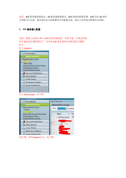
1、ACS服务器上配置说明:配置之前确认F5与ACS网络是畅通的,如果不通,先调试网络。
先在ACS服务器配置好了,这里将ACS服务器相关的配置进行截图:如下:定义location:定义device type,如下图:添加F5,使用tacacs+认证,如下图:最后完成截图:定义identity Groups:定义Device Filters,如下图:将之前添加的F5设备,添加进去。
定义Shell Profies,Command Sets:如下图:创建一条Access Sevices如下图:分别配置identity,Group Mapping,Authorization。
以上按要求进行配置,并调用之前的预定义。
选择Identity Group ,选择Shell Profile,选择Command Sets,按预先的定义进行选择 。
再创建 一条 sevice selection Rules,如下:以上配置界面,就protocol,Device Filter,service选择之前预先定义的。
最后配置完成如下:2、F5配置F5详细配置如下:先用之前本地管理员账号登陆,页面如下。
选择system,如图:展开system,选择user,再选择Authentication, 如下图:如图,按以下配置:另外需要创建相应的账号,这个账号需要与ACS赋权的一致,否则不能访问。
点击create:ROLE,Partition Accesee,Terminal Access按要求选择相应的。
完成的最后截认:这个与ACS服务器上的需要一致,如图:最后验证,通过tacacs+认证登陆成功。
F5 Networks BIG-IP DNS配置教程说明书

TRANING TERMS2021-08-30 | 2 days | Virtual Classroom2021-08-30 | 2 days | Warszawa2021-11-08 | 2 days | Kraków2021-11-08 | 2 days | Virtual ClassroomTRAINING GOALS:This course gives networking professionals a functional understanding of the BIG-IP DNS system as it is commonly used. The course covers installation, configuration, and ongoing management of the BIG-IP DNS system, and includes both lecture and many hands-on labs.Audience:This course is intended for system and network administrators responsible for installation, setup, configuration, and administration of BIG-IP DNS systems.Course is based on the system version v14.CONSPECT:Setting Up the BIG-IP SystemIntroducing the BIG-IP SystemInitially Setting Up the BIG-IP SystemArchiving the BIG-IP ConfigurationLeveraging F5 Support Resources and ToolsIntroducing the Domain Name System (DNS) and BIG-IP DNSUnderstanding the Domain Name System (DNS)Reviewing the Name Resolution ProcessImplementing BIG-IP DNSUsing DNS Resolution Diagnostic ToolsAccelerating DNS ResolutionIntroducing DNS Resolution with BIG-IP DNSConfiguring BIG-IP DNS ListenersResolving DNS Queries in the Labs (Lab Zone Records)Load Balancing Queries to a DNS Server PoolAccelerating DNS Resolution with DNS CacheAccelerating DNS Resolution with DNS ExpressIntroducing Wide IPsUsing Other Resolution Methods with BIG-IP DNSIntegrating BIG-IP DNS into Existing DNS EnvironmentsImplementing Intelligent DNS ResolutionsIntroducing Intelligent DNS ResolutionIdentifying Physical Network ComponentsIdentifying Logical Network ComponentsCollecting Metrics for Intelligent ResolutionConfiguring Data CentersConfiguring a BIG-IP DNS System as a ServerConfiguring a BIG-IP LTM System as a ServerEstablishing iQuery Communication between BIG-IP SystemsConfiguring a Non-F5 ServerDefining Links and RoutersConfiguring Wide IP PoolsConfiguring Wide IPsManaging Object StatusUsing the Traffic Management Shell (TMSH)Using LDNS Probes and MetricsIntroducing LDNS Probes and MetricsLoad Balancing Intelligent DNS ResolutionIntroducing Load Balancing on BIG-IP DNSUsing Static Load Balancing MethodsUsing Dynamic Load Balancing ModesUsing Quality of Service Load BalancingPersisting DNS Query ResponsesLogging GSLB Load Balancing DecisionsUsing Manual ResumeUsing Topology Load BalancingMonitoring Intelligent DNS ResourcesExploring MonitorsConfiguring MonitorsAssigning Monitors to ResourcesMonitoring Best PracticesAdvanced BIG-IP DNS TopicsUsing DNSSECSetting Limits for Resource AvailabilityUsing iRules with Wide IPsIntroducing Other Wide IP TypesImplementing BIG-IP DNS Sync GroupsFinal Configuration ProjectsReview QuestionsAdditional Training and CertificationGetting Started Series Web-Based TrainingF5 Instructor Led Training CurriculumF5 Professional Certification ProgramREQUIREMENTS:Before attending the Troubleshooting, ASM, DNS, APM, AAM, AFM, VIPRION or iRules courses is mandatory:to take part in the BIG-IP Admin or LTM courseor possession of F5-CA or F5-CTS LTM certificationor pass special assessment test with sore 70% or greater.To take assessment test:Step 1: get an account on F5 University https://Step 2: goto My Training and find Administering BIG-IP Course Equivalency Assessment Take the test. Pass mark is 70%Step 3: take a screen shot as proof of resultsIf this prerequisite is not met, F5 Networks have the right to refuse entry to the class.Difficulty levelCERTIFICATE:The participants will obtain certificates signed by F5 Networks (course completion).This course also will help to prepare you for the F5 Networks GTM Specialist certification (F5-CTS) exams Exam 302 - GTM Specialist, which is available through the Pearson VUE test centers.TRAINER:Certified F5 Networks Trainer.。
F5 LTM配置文档

F5 LTM配置文档目录1 连接BIGIP (3)1.1 基于Web方式 (3)1.2 基于SSH方式 (4)2 网络配置 (5)2.1 VLAN配置 (5)2.2 Self IP配置 (6)2.3 路由配置 (7)3 负载均衡配置 (8)3.1 Pool配置 (8)3.2 Virtual Server配置 (9)3.3 Monitor配置 (10)3.4 Persistence配置 (12)4 保存配置 (14)1 连接BIGIP1.1 基于Web方式1)打开浏览器(以IE为例),使用https://(BIGIP设备的IP地址),如下图:2)回车后出现系统警告信息点击Yes3)然后系统提示输入基于WEB配置的用户名和密码默认用户名和密码均为admin。
点击OK,正确后能进入BIGIP的Web界面。
类似如下:1.2 基于SSH方式使用SSH2客户端,如Secure CRT,Putty或者SSH Secure Shell。
以SSH Secure Shell为例,如下图Host Name中输入你所连接到的VLAN的Self IP或者管理端口的IP地址。
User Name中输入root。
下面根据提示输入相应密码(default)即可进入BIGIP系统。
2 网络配置2.1 VLAN配置点击左侧的导航条,进入Network VLANs点击Create:Tag:保留为空Untagged栏即可。
点击Finished完成。
2.2 Self IP配置在划分完Vlan后,即可对每个vlan进行IP地址的定义。
方法如下:点击左侧导航条中的Networks—>Self IPs点击Creat:IP address:输入IP地址Netmask:输入子网掩码Vlan:选择将这个IP地址绑定在哪个vlan上。
选择下拉菜单将显示所有已设置的vlan名。
Port Lockdown:保持默认值点击Finished完成。
2.3 路由配置点击左侧导航条中的Networks—>Routes在右侧可以对路由进行配置。
F5-BigIP配置步骤

BigIP配置目录一、网络结构 (3)二、本项目中F5的功能及配置介绍 (4)三、F5配置步骤及项目 (5)1.进入系统 (5)2.激活License (5)3.系统基本配置(hostname,TimeZone,password etc) (5)4.设备网络配置(vlan,self ip,router,floating ip etc) (5)5.负载均衡节点建立配置 (5)6.负载均衡POOL及算法建立配置 (5)7.Virtual Server建立并关联POOL配置 (5)四、F5配置信息列表 (5)1、Pool (6)2、Virtual Server (6)五、F5详细配置步骤 (8)1.进入系统配置GUI (8)2.激活License (10)3.系统基本参数配置步骤 (14)4.基本网络参数配置步骤 (15)c)配置默认路由 (21)5.Monitor的建立 (22)6.负载均衡POOL及均衡算法建立配置 (23)7.Profile的建立 (24)8.iRules建立 (26)9.Virtual Server建立配置 (26)10.配置High Availability (29)1、F5负载均衡算法及原理 (31)2、会话保持的概念 (31)一、网络结构Outside Vlan (IP Segment 172.16.6.0/24)VPN and Management Vlan (IP Segment 172.16.6.X/24)Production HTTP Proxy Vlan (IP segment 192.168.100/0/24)Production APP and DB Servers Vlan (IP segment 192.168.90.0/24) Staging Proxy Vlan (IP segment 192.168.80.0/24)Staging APP and DB Vlan (IP segment 192.168.70.0/24)Test Proxy Vlan (IP segment 192.168.60.0/24)Test APP and DB Vlan (IP segment 192.168.50.0/24)802.1Q Trunk for Vlans of Production Systems 802.1Q Trunk for Vlans of Staging and Test Systems2.12.2Failover 1.1 1.11.21.21.4 1.51.51.61.6Tape DriverManagement Vlan在SW1上预留6个端口G1/0/25G1/0/26G1/0/27G1/0/28G1/0/30G1/0/32G1/0/33G1/0/34G1/0/35G1/0/36G1/0/38 – G1/0/43G1/0/37二、本项目中F5的功能及配置介绍1. F5实现的功能When configured properly, the The BIG-IP local traffic management (LTM) systemcan perform a wide variety of traffic-management functions, such as:• Balancing traffic to tune and distribute server lo ad on the network for scalability.• Off-loading standard server tasks, such as HTTP data compression, SSL authentication, and SSL encryption to improve server performance.• Monitoring the health and performance of servers on the network for availability.• Establishing and managing session and connection persistence.• Handling application-traffic authentication and authorization functions based on username/password and SSL certificate credentials.• Managing packet throughput to optimize performance for specific types of connections.• Improving performance by aggregating multiple client requests into a server-side connection pool. This aggregation of client requests is part of the LTM system’s OneConnectTM feature.• Applying configuration settings to c ustomize the flow of application-specific traffic (such as HTTP and SSL traffic).• Customizing the management of specific connections according to user-written scripts based on the industry-standard Tool Command Language (Tcl).While some of the functions on this list offer the basic ability to balance the load on your network servers, other functions on the list offer specialized abilities that are worth noting. These abilities include managing specific types of application traffic, optimizing server performance, and enhancingthe security of your network. The following sections describe these specialized capabilities. 2. F5配置介绍1. Once you have set up your base network and you have administrative access to the LTM system, and atleast a default VLAN assignment for each interface, the next step is to configure a network for managing traffic targeted to your internal servers.2.At the heart of the LTM system are virtual servers and load balancing pools.Virtual servers receive incoming traffic, perform basic source IP anddestination IP address translation, and direct traffic to servers, which aregrouped together in load balancing pools.The three most important objects in the LTM system that you mustconfigure for local traffic management are:• Virtual servers• Load balancing pools• ProfilesThese objects are:●Virtual ServerVirtual servers receive requests and distribute them to pool members.When you create a virtual server, you specify the type of virtual server you want, that is, a hostvirtual server or a network virtual server. Then you can attach various properties and resources to it, such as application-specific profiles, session persistence, and user-written scripts called iRules thatdefine pool-selection criteria. All of these properties and resources, when associated with a virtualserver, determine how the LTM system manages local traffic.●Load balancing poolsLoad balancing pools contain servers to which requests can be sent for processing.A load balancing pool is a collection of internal servers that you group together to service clientrequests. A server in a pool is referred to as a pool member. Using the default load balancingalgorithm, known as Round Robin, the LTM system sends a client request to a member of that pool.Every pool must be associated with a virtual server. A virtual server sends client requests to thepool or pools that are associated with it.POOL. Pools have settings associated with them, such as IP addresses for pool members, load balancing modes, and health and performance monitors.● NodesNodes represent server IP addresses on your network that you can enable and disable, and forwhich you can obtain status.● ProfileProfiles contain settings that define the behavior of various traffic types.A profile is a group of configuration settings that apply to a specific type of network traffic,such as HTTP connections. If you want the virtual server to manage a type of traffic, you canassociate the applicable profile with the virtual server, and the virtual server applies that profile’ssettings to all traffic of that type.●iRULEiRules can define criteria for pool-member selection, as well as perform content transformations, logging, custom protocol support, and so on.●Rate Shaping:Rate shaping controls bandwidth consumption.●SNAT :Secure Network Address Translations (SNATs) translate the source IP address in a client request, allowing multiple hosts to share the same address.三、F5配置步骤及项目1.进入系统2.激活License3.系统基本配置(hostname,TimeZone,password etc)4.设备网络配置(vlan,self ip,router,floating ip etc)5.负载均衡节点建立配置6.负载均衡POOL及算法建立配置7.Virtual Server建立并关联POOL配置四、F5配置信息列表F5 BigIP-3400-1F5 BigIP-3400-21、Pool2、Virtual Server五、F5详细配置步骤在本次项目中,需要将两台F5 BIGIP 3400配置成Active-Standby的双机冗余模式,除了在L2-L3层的配置和Hostname外,L4-L7及其他配置相同,故以一台BIGIP 3400的配置为例。
F5 BIG-IP LTM与IBM Lotus iNotes部署指南说明书

Document version 2.1Deployment Guide Important: This guide has been archived. While the content in this guide is still valid for the products and versions listed in the document, it is no longer being updated and may refer to F5 or third party products or versions that have reached end-of-life or end-of-support.For a list of current guides, see https:///solutions/deployment-guides.A rc hi v edh Critical: Y ou must read and follow the instructions found in the following IBM link in order touse the solution presented in this guide:/developerworks/lotus/library/inotes-avail/index.html h F or more information on the iNotes configuration, see the IBM Redbook:/redbooks/pdfs/sg246518.pdfh F or optional procedures for configuring a highly available iNotes implementation withthe BIG-IP system, after completing the base configuration, see Appendix: Optional configuration for highly available implementations on page 4.Configuration exampleThe following is a sample network architecture depicting the BIG-IP managing traffic to the iNotes clients and the iNotes Domino servers. The BIG-IP provides server load balancing, high availability, server health monitoring, and SSL offload services. Additionally, the BIG-IP provides TCP and HTTP protocol optimizations, enabling a superior user experience. The BIG-IP LTMs are deployed as an active-standby pair to provide high availability.InternetBIG-IP Local Traffic ManagerIBM Lotus Domino ServersClientsFigure 1: Simple, logical configuration exampleA rc hi v edConfiguring the BIG-IP system for IBM Lotus iNotesUse the following table to configure the BIG-IP system for iNotes. The tables contain a list ofBIG-IP LTM configuration objects along with any non-default settings you should configure as a part of this deployment. Unless otherwise specified, settings not mentioned in the table can be configured as applicable for your configuration. For specific instructions on configuring individual objects, see the online help or product manuals.BIG-IP LTM ObjectNon-default settings/NotesHealth Monitor(Main tab-->Local Traffic -->Monitors )Name Type a unique name Type httpInterval30 (recommended)Timeout 91 (recommended)Send StringFor BIG-IP LTM versions 10.0 and 10.0.1GET / HTTP/1.1\r\nHOST: <Your iNotes FQDN>\r\nFor BIG-IP LTM versions later than 10.0.1GET / HTTP/1.1\r\nHOST: <Your iNotes FQDN>\r\n\r\n\r\nReceive String Lotus 1Pool (Main tab-->LocalTraffic -->Pools )NameType a unique name Health Monitor Select the monitor you created aboveSlow Ramp Time 2300Load Balancing Method Least Connections (Node)Address Type the IP Address of an iNotes nodeService Port80 Click Add to repeat Address and Service Port for all nodesProfiles(Main tab-->Local Traffic -->Profiles )Persistence(Profiles-->Persistence)Name Type a unique name Persistence Type CookieHTTP(Profiles-->Services )Name Type a unique name Parent Profile http Rewrite Redirect 3Matching 3TCP WAN(Profiles-->Protocol )Name Type a unique name Parent Profile tcp-wan-optimized TCP LAN(Profiles-->Protocol )NameType a unique name Parent Profile tcp-lan-optimized Client SSL 3 (Profiles-->SSL )NameType a unique name Parent Profile clientsslCertificate and Key Select the Certificate & Key you importedVirtual Servers(Main tab-->Local Traffic -->Virtual Servers )Name Type a unique name.Address Type the IP Address for the virtual server Service Port443 (for SSL offload) or 80 (if not offloading SSL)Protocol Profile (client)2Select the WAN optimized TCP profile you created Protocol Profile (server)2Select the LAN optimized TCP profile you created HTTP Profile Select the HTTP profile you created SSL Profile (Client)3Select the Client SSL profile you createdSNAT Pool AutomapDefault Pool Select the pool you createdPersistence ProfileSelect the Persistence profile you created1 If you modified the login screen, you may have to adjust the Receive String to match a string that appears on your home screen.2You must select Advanced from the Configuration list for these options to appear 3Only required if offloading SSL on the BIG-IP LTM. You must have already imported a valid certificate and key onto the system.This completes the base configuration.A rc hi v edAppendix: Optional configuration for highly available implementationsLotus Domino Notes servers can be deployed in several architectures. When deploying Notes in a High Availability architecture, one of these configurations is referred to as a Non-Mirrored Cluster. When configured in this manner, a user's mailbox data exists on more than one member of the cluster, but not all of the members in the cluster, as the mailbox is not replicated to all members of the cluster. IBM and F5 have created a joint solution to support this advanced architecture. There are 2 requirements for this:h T he creation of the “Load Balancer Assistance Service”. This is an additional web form,running on each server in the cluster, that provides information to the BIG-IP about the exact URL location of a user's mailbox. It inserts a custom HTTP Header containing a list of members in the cluster that have a copy of a user's mailbox.h T he creation of the BIG-IP iRule. This is high performance runtime software that will querythe cluster members, and using the information provided in the custom HTTP header, cor-rectly route each user's request to the appropriate server.You must read and understand the details of this architecture and solution before attempting to configure it in your environment. For more information on how this is configured, see the IBM Developer Works article Achieving high availability with IBM Lotus iNotes : https:///developerworks/lotus/library/inotes-avail/.Configuring the DNS settingsIn this section, you configure the DNS settings on the BIG-IP to point to the same DNS server that Lotus iNotes is using.DNS lookups go out over one of the interfaces configured on the BIG-IP system, not the management interface. The management interface has its own, separate DNS settings.The BIG-IP system must have a Route to the DNS server. The Route configuration is found on the Main tab by expanding Network and then clicking Routes. For specific instructions on configuring a Route on the BIG-IP system, see the online help or the product documentation.T o configure DNS settings1. On the Main tab, expand System , and then click Configuration .2. On the Menu bar, from the Device menu, click DNS .3. In the DNS Lookup Server List row, complete the following:a. I n the Address box, type the IP address of the same DNS server that Lotus iNotes uses.b. Click the Add button.4. Click Update .Creating Data Group ListsBefore we create the iRule, we create the Data Group List that the iRule uses.It is important to name the Data Group carefully as it is referenced by the iRule we create in the next procedure. If you modify the Data Group name in step 4, you must also modify it in the iRule.ImportantNoteImportantCriticalA rc hi v edT o create an string data group1. On the Main tab, expand Local Traffic , and then click iRules .2. On the Menu bar, click Data Group List .3. In the upper right corner of the screen, click Create .4. In the Name box, type NSLOOKUPSERVER .5. From the Type list, select String .6. In the String box, type the FQDN host name, such as .7. I n the Value box, type the associated IP address, such as 10.100.100.51.8. Click Add . The entry appears in the String Records box.9. Repeat steps 6 - 9 until you have entered all IP addresses. In our example, we add our 4 servers.10. Click Finished .Creating the iRuleThe iRule that follows is a example of what is needed to implement this solution. In our example, we have the Log messages commented out. To enable logging, simply remove the comment symbol (#).Be sure to change the name of the iNotes pool to match the names you gave the pool.T o create the iRule1. On the Main tab, expand Local Traffic , click iRules , and then click the Create button.2. In the Name box, give the iRule a unique name. We use inotes_irule .3. I n the Definition section, copy and paste the iRule on the following page, omitting the linenumbers.Note : L ogging has been completely commented out of the iRule below for best performance.For troubleshooting or debugging you should uncomment the logging statements in the iRule.Because of the length of the iRule, instead of copying and pasting it from the following pages, you can download it:/solution-center/deployment-guides/files/inotes-irule.txt 4. Click the Finished button.CriticalThis rule continues on the following pageA rModifying the virtual server to reference the iRuleThe next task is to modify the virtual server you created in Creating the virtual server, on page 9 to use the iRule you just created.T o modify the existing virtual server1. On the Main tab, expand Local Traffic , and then click Virtual Servers .2. F rom the Virtual Server list, click the iNotes virtual server you created. In our example, we click inotes-vs .3. On the Menu bar, click Resources . The Resources page for the virtual server opens.4. In the iRules section, click the Manage button. The Resource Management screen opens.5. F rom the Available list, select the iRule you just created and then click the Add (<<) button. In our example, we select inotes-irule .6. Click the Finished button.This completes the configuration.A rc8F5 Networks, Inc.Corporate Headquarters ***********F5 Networks, Inc. 401 Elliott Avenue West, Seattle, WA 98119 888-882-4447 F5 Networks Asia-Pacific ***************F5 Networks Ltd.Europe/Middle-East/Africa ***************F5 Networks Japan K.K.***************Document Revision History。
- 1、下载文档前请自行甄别文档内容的完整性,平台不提供额外的编辑、内容补充、找答案等附加服务。
- 2、"仅部分预览"的文档,不可在线预览部分如存在完整性等问题,可反馈申请退款(可完整预览的文档不适用该条件!)。
- 3、如文档侵犯您的权益,请联系客服反馈,我们会尽快为您处理(人工客服工作时间:9:00-18:30)。
• Traffic Management Module • TMOS的核心进程,有自己独立的内存、CPU资源分配和 I/O控制 • 所有的生产流量都通过TMM接收 • 一个CPU Core只能有一个TMM进程 • 在V9版本上,15/34/64/68都是单TMM运行 • 在V9版本上,16/36/69/89/84/88都是多TMM运行 • 在V10版本上,16/36/69/89/84/88都是多TMM运行 • Viprion只支持9.6和10.0版本,默认都是多TMM运行
• • • • • •
TMM只是负责客户端连接的分配和转发,不改变TCP连接中的任何参数 客户端和服务器自行协商TCP传输参数 在34/64/68平台上Performance L4可以有PVA加入实现硬件加速 在15/16/36/69/89/Viprion平台上都通过TMM核心进行处理 Performance L4 VS上只有4层的iRules可以使用 默认状态下,新建连接的第一个包必须是Syn包,如果是其他的数据包 比如ACK、RST等如果不在连接表中,则全部丢弃。 • 在Fast L4 profile打开Loose close和Loose Initial的时候对非Syn包也 可以建立连接表
Fowarding VS(Forwarding IP)
客户端 查询本地路由表
转发客户端请求
TMM
• 只能使用Fast L4 Profile • 按照连接处理,类似于路由器工作,但不完全一样,在Fast L4 Profile中开启Loose Initial和Loose Close之后更为接近路由工作模式 • 所有穿过Fowarding VS的连接都将产生连接表 • 没有Pool Member,转发完全取决于本地路由 • 可以使用基于4层的Rules
XML
SSL
iRules
Server
Virtual Server
iControl API
• Rules的处理必须依赖于VS对流量的接收 • 通过事件触发机制,Rules可以控制流量在VS内部处理的整个过程
TCP Proxy
Client Side Server Side
Server
iRules
Client Side Event Client_accept Client_data Cache_request DNS_request HTTP_REQUEST HTTP_REQUEST_DATA RTSP_REQUEST . . . . Server Side Event Server_connect Server_data Cache_response DNS_response HTTP_RESPONSE HTTP_RESPONSE_DATA RTSP_RESPONSE . . . .
Console
BIGIP 内部结构-Mecury平台16/36/69/89
TM/OS Host OS
Web 界面管理 健康检查 SNMP ……..
Cluster Muti Processor 多CPU并行处理
独立的管理机 AOM
管理CPU
TMM TMM TMM TMM 0 1 2 3
SSL加解密
HTTP压缩
重要的Profile-TCP • 注意在Client Side和Server Side可以使 用不同的TCP Profile • 通常情况下建议: – Client side:TCP WAN Optimized 或LAN Optimized – Server side: TCP LAN Optimized • 除非你非常了解TCP的工作原理,否则不 要调整除idel Timeout以外的任何参数
Standard 模式下的攻击防护
• Standard VS模式具有天然的防攻击功能 • 在遇到Syn攻击的时候会导致系统的连接表过大 • 通过System-SYN Check Activation Threshold 的设置,在达到设置值的时候系统自动启动 Syn Cookie,避免建立过多连接,这个值对全局生效 • 大部分的网络层攻击都无法通过Standard模式的VS
Standard VS
Syn Syn,Ack
Ack
Syn Syn-Ack TMM Ack Data
Data
• • • •
正常情况下客户端连接和服务器端连接是1:1的关系 默认工作在全代理模式,客户端和服务器端的TCP连接完全独立 客户端和服务器端的TCP参数都是由TMM和双方分别协商 默认情况下以客户端源IP和后台建立连接,在打开SNAT的情况下用 SNAT地址和后台建立连接 • Standard VS的端口永远对外开放,无论后台是否有服务器在工作
重要的Profile-Client SSL
客户端
SSL
SSL SSL
服务器端
客户端
服务器端 TMM
服务器端
客户端
• 对所有进入VS的流量按照SSL协议进行处理 • 注意Client SSL profile不一定只能使用在HTTPS上 • 使用Client SSL的VS不一定使用443端口
VS CLIENT_ACCPTED CLIENT_DATA LB_SELECTED SERVER_ACCPTED SERVER_DATA LB_FAILED SERVER_CLOSED CLIENT_CLOSED RULE_INIT
• 大部分rules只在同一个VS之内有效 • Rules内创建的变量以连接为生命周期 • 一个VS上可以有多个Rules,它们将被顺序执行
F5 BIG-IP LTM详解
北京先进数通信息技术有限公司 2014年3月
LTM工作原理
• • • • • • • • LTM基础架构 VS Type详解 Profile详解 CMP 工作原理 One Connect工作原理 NAT、SNAT工作原理 Monitor工作原理 HA工作原理
LTM基础架构
HiSpeed Bridge
万兆/千兆交换端口 Admin 6 Console
Host和TMM的内存分配
TMM Memory
• Host在启动的时候限 定了内存分配的大小 ,在没有其他module 的情况下是384MB • TMM进程启动后,将 自动获取余下的所有 物理内存
Host Memory
查看Host内存占用情况 • # physmem /查看物理内存大小 8387584 • b memory show /查看内存分配情况 MEMORY STATISTICS -| (Host) Total = 3.835GB Used = 3.590GB | (TMM) Total = 5.976GB Used = 93.22MB
Fast HTTP
客户端 服务器端
客户端
服务器端 TMM
客户端
服务器端
• Fast HTTP VS仅用于HTTP协议 • 默认开启One Connect Profile,对客户端连接进行聚合处理 • 默认开启SNAT AutoMap,在服务器端收到的TCP连接请求都是来自 于TMM • 没有会话保持功能 • 不能处理SSL,HTTPS
BIGIP 内部结构-V9平台15/34/64/68
TM/OS Host OS
Web 界面管理 健康检查 SNMP ……..
独立的管理机 SCCP 管理CPU
TMM 0
Bridge
SSL加解密
HTTP压缩
PVA(Packet Velocity ASIC) 四层交换专用ASIC Admin 万兆/千兆交换端口
Profile详解
Profile的作用和工作范围 • Profile依赖于VS • Profile是对VS的流量进行格式化处理 • 举例如果一个VS上配置了TCP Profile, 则该VS对所有的UDP流量都不会接收
• 基本流量处理类型Profile – TCP, UDP, FastHTTP, Fast L4, SCTP( Stream Control Transmission Protocol ) • 服务流量处理类型Profile – HTTP, FTP, SMTP, RTSP( Real Time Streaming Protocol ), SIP( Session Initiation Protocol ), iSession • SSL处理类型 – Client SSL,Server SSL • 会话保持类型 – Cookie, Destination IP, hash, msrdp, source IP, Universal, SSL • 认证处理类型 – Radius, CRLDP( Constraint-Based Label Distribution Protocol ), OCSP( Online Certificate Status Protocol ) • 其他处理类型 – One Connect, Statistics, NTLM( NT LAN Manager ), Stream
重要的Profile-FastL4
可能调整的参数 • Reset on Timeout: 在连 接达到Time out的是否 向两端发送Reset包 • Idel Timeout:多长时间 连接里面没有数据流量 的时候就删除连接表 • Loose Initiation/Loose Close: 是否接收非Syn 包建立连接 • Softare Syn Cookie Protection:是否在VS上 启用Syn Cookie,实现 Syn攻击防护
VS和Profile
HTTP
RTSP SMTP
SIP
One Connect Streaming FastL4 Profile
Client SSL
Server SSL
TCP Profile
UDP Profile VS
