工程力学英文版课件13 Deflection of Beams Due to Bending
工程力学双语课件ch13-Shear Force and Bending Moments in Beams

perpendicular to the section when the beam is bending.
2). Shearing force:Q
Internal force which the acting line in the cross-section parallel to the section, when the beam is bending.
symmetry, or the external forces do not act in a plane of symmetry of the beam with symmetric planes, this kind of bending is called unsymmetrical
bending. In later chapters we will mainly discuss the bending stresses and
Uniformly distributed force
P—
Concentrated force
5). Statically determinate and statically indeterminate beams
Statically determinate beams:Reactions of the beam can be determined only by static equilibrium equations,such as the above three kinds of basic beams. Statically indeterminate beams: Reactions of the beam cannot be determined or only part of reactions can be determined by static equilibrium equations.
力学英文术语表-SF整理
力学英文术语表-SF整理Mechanics Glossary 力学术语表Chapter1Stress应力1.1 Introduction引言1.2 Equilibrium of a Deformable Body变形体的平衡1.3 Stress应力1.4 Average Normal Stress in all Axially Loaded Bar轴向加载杆的平均正应力1.5 Average Shear Stress平均剪应力1.6 Allowable Stress容许应力Chapter2Strain应变2.1 Deformation变形2.2 Strain应变Chapter3Mechanical Properties of Materials材料的力学性质3.1 The Tension and Compression Test拉伸和压缩试验3.2 The Stress—Strain Diagram应力一应变图3.3 Stress—Strain Behavior of Ductile and Brittle Materials塑性和脆性材料的应力一应变特性3.4 Hooke’s Law虎克定律3.5 Strain Energy应变能3.6 Poisson’s Ratio泊松比3.7 The Shear Stress—Strain Diagram剪切应力一应变图Chapter4Axial Load轴向荷载4.1 Saint—Venant’s Principle圣文南原理4.2 Elastic Deformation of an Axially Loaded Member轴向加载杆件的弹性变形4.3 Principle of Superposition叠加原理4.4 Statically Indeterminate Axially Loaded Member静不定轴向加载杆件4.5 The Force Method of Analysis for Axially Loaded Members分析轴向加载杆件的力法4.6 Thermal Stress热应力4.7 Stress Concentrations应力集中Chaoter5Torsion扭转5.1 Torsional Deformation of a Circular Shaft圆轴的扭转变形5.2 The Torsion Formula扭转公式5.3 Power Transmission功率传递5.4 Angle of Twist扭转角5.5 Statically Indeterminate Torque-Loaded Members静不定受扭杆件5.6* Solid Noncircular Shafts实非圆截面轴Chapter6Bending弯曲6.1 Graphical Method for Constructing Shear and Moment Diagrams绘制剪力和弯矩图的图解法6.2 Shea rand Moment Diagrams剪力和弯矩图6.3 Bending Deformation of a Straight Member直杆的弯曲变形6.4 The Rexure Formula弯曲公式6.5 Unsymmetric Bending非对称弯曲Chapter7TrallsverseShear横向剪力7.1 Shearin Straight Members直杆中的剪力7.2 The Shear Formula剪切公式7.3 Shear Stresses in Bearns梁中的剪应力7.4 Shear Flow in Built-up Members组装杆件中的剪力流7.5 Shear Flow in Thin-Walled Members薄壁杆件中的剪力流7.6* Shear Center剪切中心Chapter8Combined Loadings组合荷载8.1 Thin-Wailed Pressure Vessels薄壁压力容器8.2 State of Stress Caused by Combined Loadings组合荷载引起应力状态Chapter9Stress Transformation应力转换9.I Plane-Stress Transfotination平面应力转换9.2 General Equations of Plane-Stress Transformation平面应力转换的一般公式9.3Principal Stresses and Maximum In—Plane Shear Stress主应力和平面内最大剪应力9.4 Mohr’s Circle—Plane Stress莫尔圆一平面应力9.5 Stress in Shafts Due to Axial Load and Torsion轴向荷载和扭矩引起的轴中应力9.6 Stress Variations Throughout a Prismatic Beam等截面梁内应力变化9.7 Absolute Maximum Shear tress所有方向上最大剪应力Chapter10Strain Transformation应变转换10.1 Plane Strain平面应变10.2 General Equations of Plane-Strain Transformation平面应变转换的一般公式10.3 Strain Rosettes应变花10.4 Material—Property Relationships材料性质关系10.5* Theories of Failure失效理论Chapter11Design of Beams and Shafts梁和轴的设计11.1 Basis for Beam Design梁设计基础11.2 Prismatic Beam Design等截面梁/柱状梁设计11.3* Fully Stressed Beams满应力梁11.4* Shaft Design轴设计Chapter12Deflections of Beams and Shafts梁和轴的挠度12.1The Elastic Curve弹性曲线12.2 Slope and Displacement by Integration积分求斜率和位移12.3 Method of Superposition叠加法12.4 Statically Indeterminate Beams and Shafts静不定梁和轴12.5 Statically Indeterminate Beams and Shafts—Method of Integration静不定梁和轴一积分法12.6 Statically Indeterminate Beams and Shafts—Method of Superposition静不定梁和轴一叠加法Chapter13Buckling of Columns柱的屈曲13.1 Critical Load临界荷载13.2 Ideal Column with Pin Supports两端铰支的理想柱13.3 Columns Having Various Types of Supports有各种支承的柱13.4* Secant Formula正割公式13.5* Inelastic Buckling非弹性屈曲Chapter14Energy Methods能量法14.1 External Work and Strain Energy外力功和应变能14.2 Elastic Strain Energy for Various Types of Loading各种荷载下的弹性应变能14.3 Conservation of Energy能量守恒14.4 Impact Loading冲击荷载14.5* Castigliano’s Theorem卡氏定理14.6* Castigliano’s Theorem Applied to Trusses卡氏定理在桁架上的应用14.7* Castigliano’s Theorem Applied to Beams卡氏定理在梁上的应用Appendix A Geometric Properties of an Area面积的几何性质A.1 Centroid of an Area面积的形心A.2 Moment of Inertia for an Area面积的惯性矩A.3 Product of Inertia for an Area面积的惯性积A.4 Moments of Inertia for an Area about Inc lined Axes面积对斜轴的惯性矩Appendix B Geometric Properties of Structural Shapes结构型钢的几何性质Appendix C Slopes and Deflections of Beams梁的转角和托度Answers参考答案Glossary术语。
材料力学(理工科课件)第六章 弯曲变形)

§6-1 基本概念及工程实例 (Basic concepts and example problems)
一、工程实例(Example problem)
(Deflection of Beams)
但在另外一些情况下,有时却要求构件具有较大的弹性变 形,以满足特定的工作需要.
例如,车辆上的板弹簧,要求有足够大的变形,以缓解车辆受
M 0 w 0
x
O
M 0 w 0
M
(Deflection of Beams)
w (1 w )
2 3 2
M ( x) EI
2 w 与 1 相比十分微小而可以忽略不计,故上式可近似为
w"
M ( x) EI
(6.5)
此式称为 梁的挠曲线近似微分方程(differential equation of the deflection curve) 近似原因 : (1) 略去了剪力的影响; (2) 略去了 w2项; (3) tan w w( x )
x Cx D
4
(Deflection of Beams)
边界条件x=0 和 x=l时, w 0
梁的转角方程和挠曲线方程 A 分别为 q 2 3 3 (6lx 4 x l ) 24 EI qx 2 3 3 w (2lx x l ) 24 EI 最大转角和最大挠度分别为 在 x=0 和 x=l 处转角的绝对值相等且都是最大值,
A a l D B
b
(Deflection of Beams)
解: 梁的两个支反力为
FRA F FRB F b l a l
x
l x
F FRA
A 1 a D b 2
Chapter 6. Bending Deformation 材料力学教学课件 英文版

x a :1 2 , v1 v2
To be continue…(出现了四个积分常 数,确定它们需要两个边界条件和两 个连续条件。计算过程较为繁琐)
Solution II : method of singular function (奇异函数法).
1. moment equations
x3
F 6
(x
a)3
C2x
D2
Chapter 6. Bending Deformation
6.3 Direct Integration Method Method of singular function (奇异函数法)
Fn
x
dx 1 n 1
xa
n1
Fn
x
xa
n
x an
0
(x a) (x a)
dFn x dx
利用奇异函数,可以将弯矩和剪力方程写成统一形式,
n
F0
x a n1
n0
无论有几个力区。基本步骤如下:
1
1. 采用统一坐标系,原点选在梁的左端;
a
x
2. 若均布载荷没有作用到最右端,将其延续到底,延续部分将 F1 作用反向均布载荷;
n 1
3. 在最右段用截面法列剪力、弯矩方程,用设正法;
6
24
3. boundary condition
max 8EIz
x l:v 0, 0
ql3 ( )
max 6EIz
C ql3 6
D ql4 8
Chapter 6. Bending Deformation
6.3 Direct Integration Method
工程力学全英文Engineering Mechanics (31)

Part II:Mechanics of MaterialsTorsionStudy object: A long straight member subjected to a torsional loading •How to determine the stress distribution?•How to determine the angle of twist?•Statically indeterminate analysis of the member in torsion?Torsion:If a member is subjected to the action of a pair of moments which are of a common magnitude and opposite senses,and lie in planes perpendicular to the longitudinal axis,the member is said to be in torsion.Screwdriver bar Transmission shaftTorque: a moment that tends to twist a member about its longitudinal axis. Shaft: a member that deforms mainly in torsion.Assumptions :•The cross section remains a plane,and the size and shape remain the same (a rigid plane).•The cross section rotates about the longitudinal axis through an angle.The small element on the surface is under pure shear:By observation :Longitudinal lines : remain straight , twisted angle;the length of shaft remains unchangedRadial lines : remain straight and rotate about the center of the cross sectionCircumferential lines : remain the same and rotate about the longitudinal axis TORSIONAL DFORMATION OF A CIRCULAR SHAFT t M tMAngle of twist : the relative angular displacement between two cross-sections,()x φ The angle of twist varies linearly with x .()x φφ∆The angle of twist of the back face: ()x φThe angle of twist of the front face: ()x φφ+∆causes the element to be subjected to a shear strain.Isolate an element from the shaft After deformation Before deformationIf andx dx ∆→d φφ∆→Since and are the same for all points on the cross section at x dφdxThe shear strain within the shaft varies linearly along any radial line from zero to .max γρd constant dx φ=at a specific position x c cdx d ///max γργφ==max γργ⎪⎭⎫ ⎝⎛=cImportant points (review)☐Assumptions:for a shaft with a circular cross section subjected to a torque.•The cross-section remains a plane•The length of the shaft and its radius remain unchanged•Its radial lines remain straight and circles remain circular☐The shear strain varies linearly along any radial line.r If the material is linear-elastic, then Hooke’s law applies, G τγ=A linear variation in shear strain leads to a corresponding linear variation in shear stress . The integral depends only on the geometry of the shaft.2max max A T dA J c c ττρ==⎰Polar moment of inertia max ()()A A T dA dA c ρρτρτ==⎰⎰Each element of area located at ,is subjected to aforce of .The resultant internal torque producedby this force is dA ρ()dT dA ρτ=()dF dA τ=TORSIONAL FORMULAmax γργ⎪⎭⎫ ⎝⎛=c max τρτ⎪⎭⎫ ⎝⎛=cT J ρτ=wheremaxτT :c :J :Torsional formulaPolar moment of inertia()cc A cd d dA J 0403022)41(222ρπρρπρπρρρ⎰⎰⎰====42c J π=Note: J is a geometric property of the circular area and is always positive. The commonunit is mm 4Solid shaft Tubular shaft ()4402i c c J -=πO 2cρρd d 2d =A O 2c i 2c 0ρρdThe internal torque T develops a linear distribution of shear stress along each radial line in the plane of the cross-section,it also develops an associated shear-stress distribution along an axial plane.Why?T Jρτ=The internal torque T develops a linear distribution of shear stress along each radial line in the plane of the cross-section,it also develops an associated shear-stress distribution along an axial plane.Why?(complementary property of shear stress))(x TAbsolute Maximum Torsional Stress of a shaft -A torque diagramThis diagram is a plot of the internal torque T versus its position x along the shaft length. Sign convention: By right-hand rule, if the thumb directs outward from the shaft, then the internal torque is positive.The Procedure of Analysis to determine the shear stress for a shaft under torsion1. Internal Loading (Torque)Section the shaft perpendicular to its axis at the point where the shear stress is to be e free-body diagram and the equilibrium equations to obtain the internal torque.2. Cross Section Properties (Polar moment of inertia )3. Shear Stress Distribution (Torsional formula)T J ρτ=42c J π=()4402i c c J -=πJTc =max τThe shaft is supported by two bearings and is subjected to three torques. Determine the shear stress developed at point A and B , located at section a-a of the shaft.Example 1ABInternal Torque.The bearing force reactions on the shaft are zero, since the applied torques satisfy moment equilibrium about the shaft’s axis.The free body diagram of the left segment.mkN T T m kN m kN M x ⋅==-⋅-⋅=1250030004250 ;0∑ABmkN T ⋅=1250AB Cross Sectional Property. The polar moment of inertia for the shaft is 474 )10(97.4) 75(2mm mm J ==πShear Stress. Since point A is at ρ=c = 75 mm and point B at ρ= 15 mmGPa mm kN mm mm m kN J Tc A 89.1/89.1)10(97.4)75)(1250(247==⋅==τGPa mmmm m kN J T B 377.0)10(97.4)15)(1250(47=⋅==ρτAns.Important points (review)☐For a linear elastic homogenous material, the shear stress along any radial line of the shaft varies linearly from zero to a maximum value at the outer surface.☐The shear stress is also linearly distributed along an adjacent axial plane of the shaft due to the complementary property of shear stress.☐Torsional formula:valid for a shaft with circular cross-section and made of homogenous material with a linear-elastic behavior.Deformation of the shaftdxd γφρ=(linear elastic material)d dxρφγ=)(/)(x J x T ρτ=Gx J x T )(/)(ργ=γτG =dxGx J x T d )()(=φANGLE OF TWISTdxGx J xT d )()(=φIntegrating over the entire length L of the shaft,⎰=Ldx Gx J x T 0)()(φTORSIONJGTL =φ∑=JGTL φConstant Torque and Cross-Sectional Area⎰=L dx Gx J x T 0)()(φ⎰=Ldx E x A x P 0)()(δAEPL =δ(Axially loaded bar)TTT 2T 1T 3Sign ConventionRight-hand rule,the torque and angle will be positive,provided the thumb is directed outward from the shaftTo determine the angle of twist of one end of a shaft with respect to the other end:1. Internal Loading (Torque)•The method of section and the equation of moment equilibrium2. Angle of Twist•The polar moment of inertia J (x );•or •A consistent sign convention for the shaftGdx x J x T )(/)(⎰=φJG TL /=φ✓If the torque varies continuously along the shaft’s length, a section should be made at the arbitrary position, T (x )✓If several constant external torques exist, the internal torques in each segment between any two external torques much be determined (a torque diagram)The Procedure of AnalysisExample 2The two solid steel shafts shown are coupled together using the meshed gears. Determine the angle of twist of end A of the shaft AB when the torque T=45N·m is applied.G=80GPa.Shaft AB is free to rotate within bearing E and F,whereas shaft DC is fixed at D.Each shaft has a diameter of20mm.1. Internal Torque. F ree body diagrams of the shafts are shown in figures. Step 1:Solution300Nm 150.0m/45N m 150.0/,0m 150.00=⋅===⨯-→=∑T F F T MABx ()()mN 5.22m 075.0N 003m 075.0,0-m 075.00⋅=⨯=⨯==⨯=F T T F Mx D x D CDx ∑→2. Angle of Twist.To solve the problem, we need to calculate the rotation of gear C with respect to the fixed end D in shaft DC .rad 0269.0]N/m )10(80[)m 010.0)(2/()m 5.1)(m N 5.22(294/+=⋅+==πφJG TL DC DC Since the two gears are in mesh, of gear C causes gear B to rotate C φBφrad0134.0 )m 075.0)(rad 0269.0()m 15.0(=→=B B φφm 010.0=c GPa80=GThen we need to determine the angle of twist of end A with respect to end B of shaft AB .The rotation of end A is therefore determined by adding and since bothangles are in the same direction .B φB A /φrad0.0850 rad 0.0716rad 0134.0/+=+=+=B B A A φφφAns.m 010.0=c GPa 80=G rad0134.0 =B φHomework assignments: 5-3, 5-9, 5-27, 5-38,5-58, 5-71()()()()()[]rad 0716.0m/N 1080m 010.02/m 2m N 45294/=⋅+==πϕJG TL AB BAEquilibrium:;0=--=∑B A xT T T MThere are two unknowns, therefore this problem is indeterminate.Compatibility or the kinematic condition: two ends are fixed:/=B A φSTATICALLY INDETERMINATE TORQUE-LOADED MEMBERS=-JGL T JG L T BC B AC A ()BC ACL LL +=⎪⎭⎫⎝⎛=L L T T BC A ⎪⎭⎫ ⎝⎛=L L T T AC B TORSION;0∑==B A xT T T M-- ;0=/BA φThe Procedure of AnalysisTo determine the unknown torques in statically indeterminate shafts:•Equilibrium equationsDraw a free-body diagram of the shaft to identify all internal torques.Write the equations of moment equilibrium about the axis of the shaft.•CompatibilityExpress the compatibility condition in terms of the rotational displacements caused by the reactive torques.•Solving unknownsSolve the equilibrium and compatibility equations for the unknown reactive torques.Pay attention to the sign of the results.Example 3The shaft is made from a steel tube,which is bonded to a brass core.A torque of T=250N·m is applied at its end,plot the shear-stress distribution along a radial line of its cross-section.(G st=80GPa,G br=36GPa)Solution:Equilibrium. A free-body diagram of the shaft . The reaction has been represented by twounknown amount of torques resisted by the steel, T st and by the brass, T br .m N 250=⋅+--br st T T Compatibility. The angles of twist at fixed end A should be the same for both the steel and brass since they are bonded together .brst φφφ==Applying the load-displacement relationship , , we haveJG TL /=φbrbr br st st st J G LT J G L T =brst T T 33.33=(1)(2)m N 28.7m N 72.242⋅=⋅=⇒br st T TThe shear stress in the brass core varies from zero at its center to the maximum at the interface, using the torsional formulaMPa 63.4mm)/2)(10(mm)mm/m)(10 m)(10N 28.7()(43max =⋅==πτbr br br J c T For the steel, the minimum shear stress is at this interfaceMPa 30.10])mm 10(mm) /2)[(20(mm) mm/m)(10 m)(10N 72.242()(443min=-⋅==πτst inner st st J c T The maximum shear stress is at the outer surfaceMPa 630.20])mm 10(mm) /2)[(20(mm)mm/m)(20 m)(10N 72.242()(443max =-⋅==πτst outer st st J c Tm N 28.7mN 72.242⋅=⋅=br st T Trad )10(1286.0N/mm)10(36N/mm 63.43232-===G τγAns.Homework assignments: 5-75, 5-82, 5-85The shear stress is discontinuous at the interface because the materials have different moduli .The stiffer material (steel)carries more shear stress.However,the shear strain is continuous at the interface.Shear strain at the interface:MPa63.4)(max =br τMPa30.10)(min =st τMPa630.20)(max =st τ。
工程力学全英文Engineering Mechanics (34)

Part II:Mechanics of Materials Combined loadingsCOMBINED LOADINGSObjects of the section:•To analyze the stresses in thin-walled pressure vessels•To develop methods to analyze the stress in members subject to combined loadings(e.g. tension or compression, shear, torsion, bending moments).“Thin wall ”: A vessel having an inner-radius-to-wall-thickness ratio of 10 or more (r/t>= 10).The results of a thin-wall analysis will predict a stress that is approximately 4%less than the actual maximum stressIt is assumed that the stress distribution throughout the vessel’s thickness is uniform or constant.Cylindrical Vessels•A pressure p is developed within the vesselby a contained gas or fluid;•An element shown in the figure is assumedto be subjected to normal stress σ1in thecircumferential or hoop direction and σ2inthe longitudinal or axial direction.•Both stress exert tension on the materialPlane stressFor the hoop stress, the vessel is being sectioned by planes a, b and c.The uniform hoop stress σ1, acting throughout the vessel’s wall, the pressure acting the vertical face of the sectioned gas or fluid.10; 2[( )](2 )0x F t dy p r dy σ=-=∑1pr tσ=It can be imagined as the solidvertical face with p acting.For the axial stress, the vessel is being sectioned by the plane b .The uniform axial stress σ2, acting throughout the vessel’s wall, the pressure p acting the section of gas or fluid. It is assumed that the mean radius r is approximately equal to the vessel’s inner radius.220; (2)()0y Frt p r σππ=-=∑2pr σ=It can be imagined asthe solid section facewith p acting.1pr t σ=22pr tσ=σ1, σ2= the normal stress in the hoop and longitudinal directions, respectively. Each is assumed to be constant throughout the wall of the cylinder, and each subjects the material to tension .p = the internal pressure developed by the contained gas or fluidr = the inner radius of the cylindert = the thickness of the wall (r/t >=10)Spherical Vessels•A pressure p is developed within the vesselby a contained gas or fluid;•An element shown in the figure is assumedto be subjected to normal stress σ2, whichexerts tension on the material.the vessel is sectioned in half using section plane a. Equilibrium in y direction requires:220; (2)()0y F rt p r σππ=-=∑22pr t σ=It can be imagined asthe solid section facewith p acting.THIN-WALLED PRESSURE VESSELS☐Either a cylindrical or a spherical vessel is subjected to biaxial stress.☐The material of the vessel is also subjected to a radial stress σ3, which acts along a radial line. The maximum of it equals to p at the interior wall and decreases to zero at the exterior wall.☐The radial stress σ3will be ignored because σ1and σ2are 5 to 10 times higher than σ3.☐External pressure might cause the vessel to buckle.A member is subjected either an internal axial force, a shear force, a bending moment, or a torsional moment.Several these types of loadings are applied to the member simultaneouslyPrinciple of SuperpositionResultant stress distribution caused by the loads.•A linear relationship exists between the stress and the loads •The geometry of the member should not undergo significant changeAssumptions STATE OF STRESS CAUSED BY COMBINED LOADINGSThe Procedure of Analysisto determine the resultant stress distribution caused by combined loadingsInternal Loadings•Section the member perpendicular to its axis at the point where the stress to be determined and obtain N,M,V and T.•The force components should act through the centroid of the cross section and the moment components should be computed about the centroidal axes .Average Stress Components•Compute the stress component associated with each internal loading.(Distribution of stress acting over the entire cross-sectional area or the stress at a specific point)How?(The neutral axis)NORMAL FORCE P SHEAR FORCE V BENDING MOMENT TORSIONAL MOMENT or THIN-WALLED PRESSURE VESSELS: and SuperpositionOnce the normal and shear stress components for each loadings have beencalculated, use the principle of superposition and determine the resultant normal and shear stress components.x P Aσ=VQ Itτ=y z x z yM z M y I I σ=-+T Jρτ=2m T A t τ=1pr tσ=22pr t σ=Important points (review)☐Pressure vessels: For a thin wall cylindrical pressure vessel with r/t >= 10; the hoop stress is σ1= pr/t. The longitudinal stress is σ2= pr/2t.☐For a thin wall spherical vessels having the same normal tensile stress, which is σ= σ2 = pr/2t.1☐Superposition of stress components: The procedure to analyze the stress state ofa point for a member, which is subjected to a combined loading.Homework assignments: 8-5, 8-15, 8-21, 8-41, 8-54Example 1A force of 15000 N is applied to the edge of the member shown below. Neglect the weight of the member and determine the state of stress at pointsB and C.Solution:1. Internal Loadings. It is sectioned through B and C. For equilibrium at the section, the internal loadings is shown below.2. Stress Components.Normal Force: 150003.75MPa (100)(40)P A σ===Bending moment: The normal force distribution due to bending moment is shown below. 33(40)(100)1212bh I ==N A315000(50)11.25MPa (112)(40)(100)B B My I σ-=-=-=315000(50)11.25MPa (112)(40)(100)c c My I σ=-=-=-yz3. Superposition 3()15000(50)( 3.75)7.5 MPa (112)(40)(100)B B My P I A σ--=-+=-+-=(tension)3()15000(50)( 3.75)15 MPa (112)(40)(100)c c My P I A σ-=-+=-+-=-(compression)Example 2The member shown has a rectangular cross section. Determine the state of stress that the loading produces at point C.Solution:AB F Ax = 16.45 kN; F Ay = 21.93 kN; F B = 97.59 kN1. Internal Loadings. The support reactions on the member have been determined and shown. (Using the equations of equilibrium for the whole member)After the support reactions have known,the internalloadings at section C have been determined and shownin the right figure.2. Stress Components.Normal Force: Shear Force: C C C C It y A V It VQ ''==τSince A= 0, thus Q C = 0, τC = 0 MPa 32.1)250.0)(050.0(45.16===A N C σBending moment: Point C is located aty = c = 125 mm from the neutral axis,so the normal stress at C.MPa 15.63)250.0)(050.0(121)125.0)(89.32(3=⎥⎦⎤⎢⎣⎡==I Mc C σσC =63.15 MPa3. SuperpositionMPa 5.6415.6332.1=+=C σAns.。
Beam Displacements
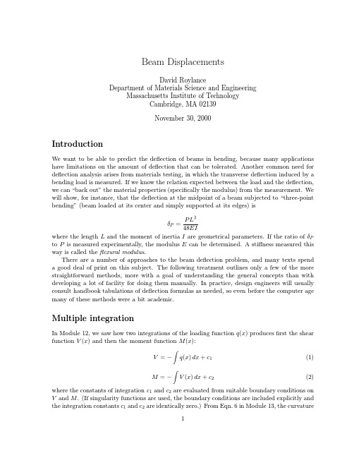
Beam DisplacementsDavid RoylanceDepartment of Materials Science and EngineeringMassachusetts Institute of TechnologyCambridge,MA02139November30,2000IntroductionWe want to be able to predict the deflection of beams in bending,because many applications have limitations on the amount of deflection that can be tolerated.Another common need for deflection analysis arises from materials testing,in which the transverse deflection induced by a bending load is measured.If we know the relation expected between the load and the deflection, we can“back out”the material properties(specifically the modulus)from the measurement.We will show,for instance,that the deflection at the midpoint of a beam subjected to“three-point bending”(beam loaded at its center and simply supported at its edges)isP L3δP=v,xx(x)is just the moment divided by the section modulus EI.Another two integrations then give1v,x(x)=P v=Figure2:Uniformly loaded beam resting on three supports.EIy(x)=EIy (x)dx=R a6x−7.5 3+R c x 4+c1x+c2These equations have5unknowns:R a,R b,R c,c1,and c2.These must be obtained from the two equilibrium equationsF y=0=R a+R b+R c−qLM a=0=qL L2−R c Land the three known zero displacements at the supportsy(0)=y(L/2)=y(L)=0Although the process is straightforward,there is a lot of algebra to wade through.Statically indeterminate beams tend to generate tedious mathematics,but fortunately this can be reduced greatly by modern software.Follow how easily this example is handled by the Maple V package(some of the Maple responses removed for brevity):>#read the library containing the Heaviside function>readlib(Heaviside);>#use the Heaviside function to define singularity functions;>#sfn(x,a,n)is same is<x-a>^n>sfn:=proc(x,a,n)(x-a)^n*Heaviside(x-a)end;>#define the deflection function:>y:=(x)->(Ra/6)*sfn(x,0,3)+(Rb/6)*sfn(x,7.5,3)+(Rc/6)*sfn(x,15,3)>-(10/24)*sfn(x,0,4)+c1*x+c2;>#Now define the five constraint equations;first vertical equilibrium:>eq1:=0=Ra+Rb+Rc-(10*15);>#rotational equilibrium:>eq2:=0=(10*15*7.5)-Rb*7.5-Rc*15;>#Now the three zero displacements at the supports:>eq3:=y(0)=0;>eq4:=y(7.5)=0;>eq5:=y(15)=0;>#set precision;4digits is enough:>Digits:=4;>#solve the 5equations for the 5unknowns:>solve({eq1,eq2,eq3,eq4,eq5},{Ra,Rb,Rc,c1,c2});{c2=0,c1=-87.82,Rb =93.78,Ra =28.11,Rc =28.11}>#assign the known values for plotting purposes:>c1:=-87.82;c2:=0;Ra:=28.11;Rb:=93.78;Rc:=28.11;>#the equation of the deflection curve is:>y(x);334.686x Heaviside(x)+15.63(x -7.5)Heaviside(x -7.5)34+4.686(x -15)Heaviside(x -15)-5/12x Heaviside(x)-87.82x>#plot the deflection curve:>plot(y(x),x=0..15);>#The maximum deflection occurs at the quarter points:>y(15/4);-164.7The plot of the deflection curve is shown in Fig.3.Figure 3:Deflection curve EIy (x )for uniformly loaded triply-supported beam (Note difference in horizontal and vertical scales).@P =∂2EIIt is usually more convenient to do the differentiation before the integration,since this lowers the order of the expression in the integrand:δP=LM=121ThenδP=1Figure5:Tapered circular beam.>r:=proc(x)r1+(r2-r1)*(x/L)end;>A:=proc(r)Pi*(r(x))^2end;>Iz:=proc(r)Pi*(r(x))^4/4end;>Jp:=proc(r)Pi*(r(x))^4/2end;where r(x)is the radius,A(r)is the section area,Iz is the rectangular moment of inertia,and Jp is the polar moment of inertia.The axial,bending,and shear loads are given in terms of F as>P:=F*cos(theta);>V:=F*sin(theta);>M:=proc(x)-F*sin(theta)*x end;The strain energies corresponding to tension,bending and shear are>U1:=P^2/(2*E*A(r));>U2:=(M(x))^2/(2*E*Iz(r));>U3:=V^2*(10/9)/(2*G*A(r));>U:=int(U1+U2+U3,x=0..L);Finally,the deflection congruent to the load F is obtained by differentiating the total strain energy:>dF:=diff(U,F);The result of these manipulations yieldsδF=LF12L2G−12GL2cos2θ+9Gr22cos2θ+10r22E−10r22E cos2θSuperpositionIn practice,many beams will be loaded in a complicated manner consisting of several concen-trated or distributed loads acting at various locations along the beam.Although these multiple-load cases can be solved from scratch using the methods described above,it is often easier to solve the problem by superposing solutions of simpler problems whose solutions are tabulated. Fig.6gives an abbreviated collection of deflection formulas1that will suffice for many problems. The superposition approach is valid since the governing equations are linear;hence the response to a combination of loads is the sum of the responses that would be generated by each separate load acting alone.Figure6:Deflections for cantilevered and simply-supported beams,under concentrated and distributed loading.1A more exhaustive listing is available in W.C.Young,Roark’s Formulas for Stress and Strain,McGraw-Hill, New York,1989.Figure7:Four-point bending.distance a from the left end isδ(x)=P bb x−a 3−x3+L2−b2x.Our present problem is justtwo such loads acting simultaneously,so we haveδ(x)=P(L−a)−ax−a 3−x3+L2−(L−a)2x+P aax−(L−a) 3−x3+L2−a2xAb2dA=10f s=12。
工程力学全英文Engineering Mechanics (5)
A
A
A
FNA A
Support Reactions and Free-Body Diagrams
4. Pin support Two or more bodies are constrained by inserting a slightly smaller pin into the holes. Commonly two perpendicular components are used to represent the reactive forces.
(3) Draw FBD for entire system
B
G
D
A
FAx
FAy
F
G
E C FC
B F
D
E
A
C
Important Points
Flexible cables can only sustain tensile loadings.
Apply the weight of the body to its center of gravity (if it is uniform, then apply it to the centroid).
Support Reactions and Free-Body Diagrams
Support Reactions and Free-Body Diagrams
Support Reactions Forces acting on a body can be divided into two general categories: reactive forces (or reactions) and applied forces (or active forces). Reactions are those forces that are exerted on a body by its supports. Forces that are not provided by the supports are called applied forces.
- 1、下载文档前请自行甄别文档内容的完整性,平台不提供额外的编辑、内容补充、找答案等附加服务。
- 2、"仅部分预览"的文档,不可在线预览部分如存在完整性等问题,可反馈申请退款(可完整预览的文档不适用该条件!)。
- 3、如文档侵犯您的权益,请联系客服反馈,我们会尽快为您处理(人工客服工作时间:9:00-18:30)。
M ( x) Px
13
Slope and Elastic Curve. Applying equation (4) and integrating twice yields
d w EI 2 Px dx 2 dw Px EI c1 dx 2 Px EIw c1 x c2 6
d w M 2 dx EI
2
(3)
9
If EI is constant, rewriting equation (3), we have 2
d w EI 2 M ( x) dx
(4)
Integrating equation (4) twice yields
dw EI M ( x)dx c1 dx
15
2
3
dw P 2 2 L x dx 2 EI P 3 2 3 w x 3L x 2 L 6 EI
Maximum slope and deflection occur at A (x = 0), for which
PL A 2 EI
2
PL wA 3EI
5
It is important that we should be able to calculate the deflection of a beam of given section, since for given conditions of span and load it would be possible to adopt a section which would meet a strength criterion but would give an unacceptable deflection. The total deflection of a beam is due to a very large extent to the deflection caused by bending, and to a very much smaller extent to the deflection caused by shear.
19
Px EIw1 c1 x1 c2 183 1源自Likewise for M2
d w2 2 P EI (3a x2 ) 2 3 dx2
16
3
[Example 2] The simply supported beam shown in figure is subjected to the concentrated force P. Determine the maximum deflection of the beam. EI is constant. Elastic Curve. Two P 2a a coordinates must be B A C x1 used, since the x2 moment becomes discontinuous at P. Here we will take x1 and x2, having the same origin at A, so that 0 x1 2a, 2a x2 3a
4
w
w F x
The elastic curve for a beam
The slope is the turning angle of the crosssectional area. The positive slope angle will be measured counterclockwise from the x axis when x is positive to the right. The slope can be determined from dw/dx.
The constants of integration are determined by evaluating the functions for shear, moment, slope, or displacement at a particular point on the beam where the value of the function is known. These values are called boundary conditions. If a single x coordinate cannot be used to express the equation for the beam’s slope or the elastic curve, the continuity conditions must be used to evaluate some of the integration constants.
3
w
w F x
The elastic curve for a beam
The x axis extends positive to the right, along the initially straight longitudinal axis of the beam. The w axis extends positive upward from the x axis. It measures the deflection of the centroid on the cross-sectional area of the element.
2
§15-1 Slope and Deflection of Beams
Introduction Having studied the stresses set up in bending, we now turn to the equally important aspect of beam stiffness. In many structural elements, such as floor joists or aircraft wings, the limiting constraint on the design is stiffness. Any design which is stiff enough will be strong enough.
7
The elastic curve for a beam can be expressed mathematically as w = f (x). To obtain this equation, we must first represent the curvature in terms of w and x. In most calculus books it is shown that this relationship is
12
[Example 1] The cantilevered beam shown in figure is subjected to a vertical load P at its end. Determine the equation of the elastic curve. EI is constant. Moment Function. w From the free-body P B x diagram, with M A x acting in the L positive direction, P we have
EIw M ( x)dx c1 x c2
2
10
Therefore, the equation of the slope and elastic curve for the beam are
dw 1 dx EI
1 w EI
M ( x)dx c
1
2
M ( x)dx
3
2
(a) (b) (c)
14
Using the boundary conditions dw / dx = 0 and w = 0 at x = L, equation (b) and (c) become
PL 0 c1 2 PL 0 c1 L c2 6
Thus, c1= PL2/2 and c2= -PL3/3. Substituting these results into equation (b) and (c), we get
17
Moment Function From the free-body diagrams shown in figure,
x1 P/3 M1
P M 1 ( x) x1 3
M 2 ( x) P x2 P ( x2 2 a ) 3 2P (3a x2 ) 3
18
2a
x2 P/3
1
1 dw / dx
d w / dx
2 2 2 3/ 2
d w / dx
2
2 2 3/ 2
Substituting into equation (1), we get
1 dw / dx
M EI
(2)
8
Most engineering design codes specify limitations on deflections for tolerance or esthetical purposes, and as a result the elastic deflections for the majority of beams and shafts form a shallow curve. Consequently, the slope of the elastic curve which is determined from dw/dx will be very small, and its square will be negligible compared with unity. Using this simplification, equation (2) can now be written as