WILLOW-安装手册
VMware-Horizon-View-6.2安装手册详细带排错(ws版)

书目一、部署环境介绍 (3)1、VIEW环境架构 (3)2、试验环境架构 (4)3、组件介绍 (4)4、相关软件版本 (5)5、测试环境信息表 (6)其次章安装ESXI6.0 (7)1、集成网卡驱动 (7)2、安装 (7)3、激活 (7)4、ntp (7)第三章AD配置 (9)1、留意事项 (9)2、修改本地密码验证策略 (12)3、创建组织单位、用户 (14)4、安装证书服务器 (15)4.1、配置本地服务器 (15)4.2、勾选默认跳过此页 (15)4.3、基本选项 (15)4.4、特殊选项 (16)4.5、完成基础安装 (17)4.6、基本配置 (17)4.7、服务器添加证书 (25)第四章SQL服务器安装部署 (31)第五章安装VCenter Server (40)1、创建数据源 (40)2、安装vCenter (45)第六章安装 (50)1、环境打算: (50)2、数据源 (50)3、起先安装,next (51)第七章安装 (53)第八章Horizon View基本配置 (55)1.vSphere 初始配置 (55)2.View 初始配置 (57)3.事务配置 (62)第九章模板的安装 (64)第十章创建桌面池 (67)第十一章接入测试 (71)1、web访问 (71)2、PC客户端 (71)3、安卓手机客户端 (72)第十二章附录:优化Windows 7 和Windows 8 客户机操作系统性能 (74)第一章部署环境介绍1、VIEW环境架构2、试验环境架构连接服务器VCenter 服务器SQL 服务器服务器ESXI 服务器管理控制台3、组件介绍ESXI将物理主机虚拟为资源池vCenter Server该服务可充当联网VMware ESX/ESXi 主机的中心管理员。
vCenter Server 供应了在数据中心内配置、部署和管理虚拟机的中心点。
除了将这些虚拟机作为View 桌面池的源,您还可以运用虚拟机来托管VMware View 的服务器组件,包括Connection Server 实例、Active Directory 服务器和vCenter Server 实例。
易安装指南说明书

2
Ensure you have the rail the correct way up. Assurez-vous que le rail est du bon côté. Asegúrese de que el riel esté puesto del lado correcto.
3
Place the bottom of the rail along the maked line. Placez le bas du rail de niveau avec la ligne que vous avez marquée. Instale la parte inferior del riel al nivel de la línea marcada.
Easy installation guide Guide d’installation facile Guía de instalación fácil
1
Mark out a horizontal line using a spirit level at your desired height on the wall.
À l'aide d'un niveau, marquez une ligne horizontale sur le mur à la hauteur désirée. Con la ayuda de un nivel de burbuja, marque una línea horizontal en la pared a la altura deseada.
wePresent 无线投手 快速安装手册
快速安裝手冊無線投手投出專業‧魅力無限版本: 1.00 日期: OCT. 12. 2007警告聲明802.11b/802.11g/BT 警語:第十二條→經型式認證合格之低功率射頻電機,非經許可,公司,商號或使用者均不得擅自變更頻率、加大功率或變更原設計之特性及功能。
第十四條→低功率射頻電機之使用不得影響飛航安全及干擾合法通信;經發現有干擾現象時,應立即停用,並改善至無干擾時方得繼續使用。
前項合法通信,指依電信法規定作業之無線電通信。
低功率射頻電機須忍受合法通信或工業、科學及醫療用電波輻射性電機設備之干擾。
802.11a 警語:4.7→無線傳輸設備(UNII)4.7.5→在5.25-5.35 秭赫頻帶內操作之無線資訊傳輸設備,限於室內使用。
4.7.6→無線資訊傳輸設備忍受合法通信之干擾且不得干擾合法通信;如造成干擾,應立即停用,俟無干擾之虞,始得繼續使用。
4.7.7→無線資訊傳設備的製造廠商應確保頻率穩定性,如依製造廠商使用手冊上所述正常操作,發射的信號應維持於操作頻帶中。
加印警語→「避免電波干擾,本器材禁止於室外使用5.25-5.35 秭赫頻帶」於器材使用說明書內,並將警語印製貼紙可黏貼於裝設器材機身外明處。
FCC 聲明:本設備已通過測試並符合 FCC 規則第 15 部分有關數位裝置的規定。
這些限制的主要目的是在保護商業區中運作此種設備時,提供合理程度的保護,避免有害干擾。
本設備會產生、使用並放射射頻能源,若不按指示手冊安裝和使用,會對無線通訊造成有害干擾。
在住宅區中運作本設備亦可能造成有害干擾,在這種情況下,使用者會被要求採用以下一種或多種方法來改善干擾的情形。
1. 調整接收天線的方向或移動其位置。
2. 將設備與接收天線的距離增加。
3. 諮詢經銷商或老練的無線電/電視技術員的協助。
這個設備遵照FCC 規則第15 節。
操作程序受限於以下二個條件:(1) 這個設備不能導致有害的干擾。
(2) 這個設備必須可接受任一種干擾, 包括可能導致非預期操作的干擾。
NetBow Installation Manual 安装说明书
V 001.02 - JUNE 2021© COPYRIGHT 2021, NETAFIM™NO PARTS OF THIS PUBLICATION MAY BE REPRODUCED, STORED IN AN AUTOMATED DATA FILE OR MADE PUBLIC IN ANY FORM OR BY ANY MEANS, WHETHER ELECTRONIC, MECHANICAL, BY PHOTOCOPYING, RECORDING OR IN ANY OTHER MANNER WITHOUT PRIOR WRITTEN PERMISSION OF THE PUBLISHER.AL THOUGH NETAFIM™ TAKES THE GREATEST POSSIBLE CARE IN DESIGNING AND PRODUCING BOTH ITS PRODUCTS AND THE ASSOCIATED DOCUMENTATION, THEY MAY STILL INCLUDE FAUL TS.NETAFIM™ WILL NOT ACCEPT RESPONSIBILITY FOR DAMAGE RESUL TING FROM USE OF NETAFIM'S PRODUCTS OR USE OF THIS MANUAL.NETAFIM™ RESERVES THE RIGHT TO MAKE CHANGES AND IMPROVEMENTS TO ITS PRODUCTS AND/OR THE ASSOCIATED DOCUMENTATION WITHOUT PRIOR NOTICE.FOREIGN LANGUAGESIn the event that you are reading this manual in a language other than the English language, youacknowledge and agree that the English language version shall prevail in case of inconsistency orcontradiction in interpretation or translation.NetBow™Container Irrigation ArcAn innovative userfriendly containerirrigation multi-outlet drippingarc with highcloggingresistance andsuperb waterdistributionSpecs. & Recommendations• Compatible with 10-60 liters (2.5-15 gallon) containers, and in many cases even smaller containers, depending on the pot geometry.• Diameter: 120, 250 mm (5, 10 inches)• Dripping outlets: 4 and 8 respectively.The flow from each one of the dripping outlets is the hub dripper flow divided by the number of dripping outlets.• Minimum operating pressure: according to hub dripper definitions.• Maximum recommended pressure at the hub dripper inlet: 4.0 bar (58 PSI)• Flow of the hub dripper should be 2.0-8.0 l/h (0.53-2.11 GPH).If your required flow / pressure is out of this range, consult your Netafim™ local representative.NETBOW™ INSTALLATION MANUAL34 NETBOW™ INSTALLATION MANUALConnection optionsNetbow™ can be connected to different hub dripper - PCJ, PC, or UniRam™ with Dr. Zip™• When connected to a hub dripper, NetBow™ can deliver flow rate as low as ¼ l/h from each one of its4 or 8 dripping outlets, while maintaining sufficient velocity for self-cleaning.PCJon linePCon lineUniRam™with Dr. Zip™NetBow™ options of hub dripperInstallation• Cut a section of 3X5 mm diameter micro-tube at the required length to reach conveniently from the hub dripper to the NetBow™ inlet. Using SPE (soft polyethylene) micro-tube is recomended for ease of installation (pre-cut SPE micro-tube sections of the required length with the required assembly fittings can be ordered).• Connect it to the barb connector of the hub dripper. If the hub dripper is fitted with a Press-Fit outlet connector, use a Press-Fit to barb adapter (see available options on page 5).6 NETBOW™ INSTALLATION MANUALACPress-Fit plug incorporated in the NetBow™ under-side.NetBow™ models with foldable spikes• Extend the 5 foldable spikes on the NetBow™ underside6 different NetBow™ models are offered• 250mm/10" with insertable spikes;• 250mm/10" with foldable spikes;• 120mm/5" with foldable spikes,each with barb or Press-Fit connector(See Product order data on page 8)Size Outlets Connector Spikes250mm/10"8BarbInsertable250m/10"Press-Fit250mm/10"Barb7• Connect the free side of the micro-tube to the NetBow™ barb inlet.For NetBow™ with Press-Fit inlet use a straight Press-Fit to barb adaptor• Place the NetBow™ on the the substrate surface in the pot, surrounding the plant location.• Insert the NetBow™ spikes into the substrate so that its underside is in contact with the substrate.NetBow™ with barb intletNetBow™ with Press-Fit intlet• Adjust the NetBow™ inlet T orientation (up/down)as to allow the optimal micro-tube position.0-45 deg.Make sure the micro-tube is not kinked, pinched or stretched.NetBow™ models with insertable spikes • Insert the 5 spikes into the 5 holes on the NetBow™ undersideContinue installation (all models)Order DetailsProduct order dataAccessoriesThe NetBow™ can be connected directly by micro-tube to Netafim™ PCJ on line drippers equiped with a barb outlet, or to PC, PCJ on line drippers and UniRam™ integral driplines with Dr. Zip™, using one of the following Netafim™ adapters (to be ordered separately):8 NETBOW™ INSTALLATION MANUALRelated assemblies*The catalog number is in units but orders will be in boxes of 500 unitsFor more information about Netafim's drippers see the drippers catalog at/irrigation-products-technical-materials.Author: Abed Masarwa, Product Management Dept., July 2021NETBOW™ INSTALLATION MANUAL9GROW MORE WITH LESS。
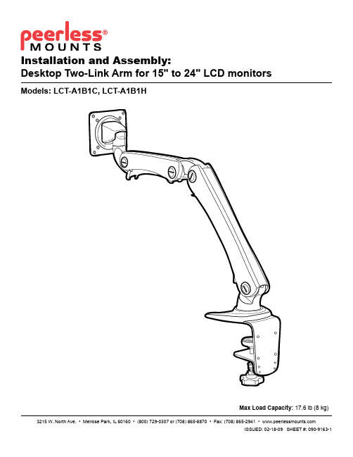
Peerless 桌面两链臂系列安装说明书
A
mounting surface
A
mounting surface
H
G
fig. 1.1
F
E
DETAIL 1
4 of 6 Visit the Peerless Web Site at
I
fig. 1.2
ISSUED: 02-18-09 SHEET #: 090-9163-1 For customer care call 1-800-729-0307 or 708-865-8870.
ISSUED: 02-18-09 SHEET #: 090-9163-1 For customer care call 1-800-729-0307 or 708-865-8870.
Control Bolt Tension Adjustment
4
NOTE: This product is factory set for a 19" (483 mm) monitor. When changing the size of the monitor, adjust the control bolt with M4 wrench as shown in figure 4.1.
product.
Table of Contents
Parts List.................................................................................................................................................................................3
wiki安装手册

Wiki 安装Wiki(5.0版本)软件安装步骤:安装PHPnow软件包(搭建PHP开发环境,安装的组件有Apache-2.0.63Apache-2.2.16MySQL-5.0.90MySQL-5.1.50PHP-5.2.14Zend Optimizer-3.3.3phpMyAdmin-3.3.7eAccelerator 0.9.6-1)1.将PHPnow-1.5.6.zip解压到一个不含中文字符的目录(重命名为PHPnow)2.切换到PHPnow目录下,双击Setup.cmd文件安装PHPnow软件3.弹出dos命令窗口,按照提示安装(Apache选择Apache 2.2.16,MySql 选择MySQL-5.1.50,PHP默认是PHP-5.2.14等)4.安装成功后会弹出页面(表示安装成功):输入密码,测试MySql是否连接成功5.浏览器地址栏输入/down.php下载互动维客HDWiki5.0 正式版(UTF-8版下载)HDWiki-v5.0UTF8-20100917.zip6.在PHPnow\htdocs目录下创建wiki文件夹,将解压wiki.rar后的文件夹下wiki文件夹下的所有文件拷贝到新建的wiki文件夹下7.浏览器地址栏输入http://localhost:80/wiki出现以下页面(在线安装页面)8.按提示进行安装9.安装成功后访问http://localhost:80/wiki/?user-login页面登陆(用户名和密码是安装hudongwiki时设置的)10.登陆进去之后可以点击系统设置,再次登陆到后台管理中心Hdwiki升级步骤:从 5.0 正式版起,HDwiki开始提供自动升级功能。
当有可用的升级时,在HDwiki后台首页会有相应红色闪烁的升级提示文字。
进入自动升级页面后,按照升级提示升级即可。
IsoVerterII Model 4380 安装指南说明书

IsoVerter®II Model 4380INSTALLATION INSTRUCTIONSMount the socket and wire per instructions on below (Figure 2).Refer to the exploded diagram in Figure 1. Carefully remove the four screws from the bottom of the plug end. Slide the cover off.Program for desired input following instructions on Page 2.Program for desired output following instructions on Page 3.Refer to the exploded diagram in Figure 1. Carefully replace the cover and re-install the four screws to secure the cover to the base. Screws should be tight-ened to a snug fit.Calibrate the unit using the procedure on page 4.WARNING: Do not attempt tooperate or calibrate this device with the cover removed. Poten-tially lethal voltage is present on some of the internal components.Make sure that the cover is firmly in place before plugging into the socket.GETTING STARTEDWIRINGWire the mounting socket as shown in the drawing shown in Figure 2.For DIRECT ACTING inputs wire the positive lead to terminal five and the negative lead to terminal six (as shown).For REVERSE ACTING inputs wire the positive input lead to terminal six and the negative lead to terminal five.INPUT PROGRAMMINGThe input selection and ranging is performed through two switch banks. Refer to the instructions below and the illustration in Figure 3 for details. MODE SELECT SWITCH BANK1.For CURRENT INPUT turn switch one ON.For VOL T AGE INPUT turn switch one OFF.2.For UNI-POLAR INPUT (low end of scale ≥ zero) turn switch twoON and turn switch three OFF.3.For BI-POLAR INPUT (low end of scale < zero) turn switch twoOFF and turn switch three ON .4.For ZERO BASED INPUT (eg. 0 to 20 mA) turn switch four ONand switch five OFF.5.For ZERO SUPPRESSION (eg. 4 to 20 mA) turn switch four OFFand switch five ON.6.For DIRECT ACTING INPUT turn switch six OFF.7.For REVERSE ACTING INPUT turn switch six ON and reverseinput wiring.RANGE SELECT SWITCH BANKT urn ON the switch for the scale desired. All other switches should be OFF. If BI-POLAR INPUT is selected, the scale will be MINUS-SELEC-TION to PLUS-SELECTION (eg. -10 TO +10VDC).© COPYRIGHT 1994 DWYER INSTRUMENTS, INC., ALL RIGHTS RESERVEDPRINTED IN U.S.A. 3/94WARNING: Do not attempt to operate or calibratethis device with the cover removed. Potentially lethal voltage is present on some of the internal components.Make sure that the cover is firmly in place before plug-ging into the socket.OUTPUT PROGRAMMINGThe output selection and ranging is performed through two switch banks.Refer to the instructions below and the illustration in Figure 4 for details.MODE SELECTION SWITCH BANK1.For VOL T AGE OUTPUT turn switches one and two ON and switchthree OFF .2.For CURRENT OUTPUT turn switches one and two OFF andswitch three ON.3.For UNIPOLAR OUTPUT turn switch four ON and switch five OFF .4.For BIPOLAR OUTPUT turn switch four OFF and switch five ON.5.For ZERO BASED OUTPUT (eg. 0 TO 20 mA) turn switch six ONand switch seven OFF .6.For ZERO SUPPRESSION (eg. 4 TO 20 mA) turn switch six OFFand switch seven ON. If BIPOLAR or REVERSE ACTION is se-lected, do not use the ZERO SUPPRESSION switch. Use the ZERO adjustment to suppress the output.7.Switch eight is always OFF . (It is not connected to any circuitry. Ifswitch eight is turned ON there is no effect on the operation of the device.)RANGE SELECTION SWITCH BANKT urn ON the switch for the scale desired. All other switches should be OFF . If BIPOLAR OUTPUT is selected, the scale will be from MINUS-SELECTION to PLUS-SELECTION (eg. -10 TO +10 VDC)Figure 4. Output Selection and Range Switches1mA 5mA 20mA1V 5V 10V BI-POLAR OUTPUTZERO + 20%OUTPUT12345678123456SELECTRANGE SELECT MODE (SWITCH 1 & 2)VOLTAGE CURRENTON ⇒ON ⇒UNI-POLARZERO BASED*** SELECT ONLY ONESPECIFICATIONSPower Supply:85 to 265 VDC / VAC 50 to 400 Hz.Isolation:1500 VACAmbient Temperature Range (operating): 0° to 50° C (32° to 131° F)Linearity:0.1%Drift:±0.02% per °C typical, ±0.05% maximum.Maximum current output load:600 ohms.Maximum voltage output load:20mA (500 ohms).Input impedence - current:10 ohms.Input impedence - voltage: 1 Megohm.CALIBRATION1.Apply the appropriate input for the lowend of the scale.2.Adjust the ZERO screw for the de-sired low end output (4mA for ex-ample).3.Apply the appropriate input for thehigh end of the scale.4.Adjust the SP AN screw for the desiredhigh end output (20mA for example).5.Repeat as necessary.Dwyer Instruments, IncorporatedPO Box 338 Michigan City, IN 46361-0338(800) 828-4588 (219) 879-8000 FAX (219) 872-9057❍❍❍WARNING: Do not attempt to operate or calibratethis device with the cover removed. Potentially lethal voltage is present on some of the internal components.Make sure that the cover is firmly in place before plug-ging into the socket.。
Helio Power System 产品安装指南说明书
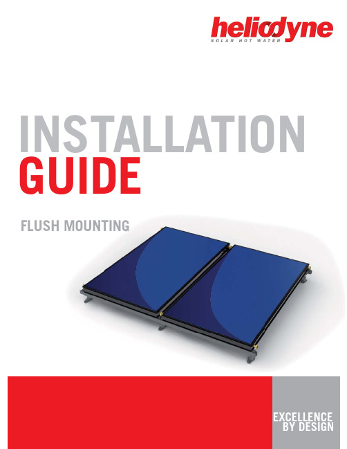
EXCELLENCE BY DESIGNINSTALLATION GUIDEFLUSH MOUNTINGFLUSH MOUNTING INSTALLATION1. FLUSH INSTALLATIONN3/8” - 16 x 1 SS Bolt11/2”- 13 SS Flange Nut3/8” - 16 SS Flange Nut1/2” - 13 x 1.25” SS Bolt 3/8” SS Flat Washer11/2”-13 x 6 SS Hanger Bolt Flush Mount Flange3/8” x 4 SS Lag ScrewTile BracketGobi Collector Clip Rail “L” Bracket1/2” SS Flat Washer3/8” x 2 SS Lag ScrewA D GB E H LNC F JKMBBGA DAKMLBFLSH 001 000Single Collector Kit - No railFLSH 000 000Shingle - Hanger Bolt KitFLSH 000 001Shingle - Flashing Flange KitFLSH 000 002Domed Terra-cotta Tile Kit1May be substituted with integrated washer head bolt without notice1.0. Flush Mounting OverviewFLUSH MOUNTING INSTALLATION3SO L A RH O T W A T E R1.1. Flush Installation1.1.0. Flush Foot Spacing>2x21.1.4. Rail Mounting 1.1.5. Collector MountingR oof Sl o p e1.1.6. Rail Splice (optional)1.1.2. Flange Mounting21.1.3. Tile Mounting 2bb3211232. Place collectors. Insert O-rings, tighten Unions. Take care not to crimp O-ring. Do not use thread lock or sealants.3. Place Helio-Clamps, and thread flanged nuts on exposed bolts and tighten securely.Heliodyne recommends using a long lasting thread locker, such as Loctite 277, on rail splice kits.Locate a 1. rafter and drill a 3/8” hole for lag portion add roof sealant; use two flange nuts backed against each other to lag bolt into roof Use one 2. flange nut face down for compression seal.Thread on 3. 2nd nut with flange upwards, then Clip or “L” bracket, then third flange nut and tighten.Locate 1. a rafter and use flange as template to drill two 3/8” holes for lag screws; add roof sealant to holes and flange.Lag in 2. screws.Place 3. OATEY 1-1/4” flashing over flange.Replace 4. shingle over flashing; follow best roofing practices to ensure seal.Remove 1. tiles. Locate a rafter and use tile bracket as template to drill three 3/8” holes for lag screws; add roof sealant to holes.Lag in 2. screws.Replace 3. tiles overbracket; follow best roofing practices to ensure seal.With bolts, flange 1. nuts and washers installed, slide all “L” brackets onto each rail into approximate position of hanger bolts, flash flange or tile bracket; ensure the washer is on the inside of the rail flange for proper strength.Insert “L” bracket 2. onto each mount.Tighten all nuts 3. and bolts for proper strength.Before 1. placing collectors, slide all clamp bolts and washers into approximate position on rails. Ensure washer is inside the rail channel for proper strength.2While lag screws are provided with most kits, consult the American Wood Council NDS 2005 for proper lag screw specifications, or verify with a certified structural engineer, for each specific roof site. Heliodyne is not responsible for mounting anchor integrity.SalesInquiries:******************* InformationandSupport:******************。
Relativity v5 Client Server for Windows 安装指南说明书

Note
_LICENSE
password number
directory user name
Start
Run
Setup OK
Amend Open
Browse
•
Yes Note
liant.lic
Finish
• At Windows Startup. • Manually.
•
Control Panel
Select Catalog
•
SAMPLES
VERIFY
RM MF
VERIFY.RCG
•
OK
OK Close
•
Close
Note Note
•
Start
Settings
Sources (32bit) Administrative Tools
Add
Control Panel
ODBC Data ODBC
Create Catalog
•
.rcg Open
OK
•
OK
•
Note
Installation and Verification of Relativity Data Client for Catalog
Development
Installation and Verification of Relativity Data
Note
liant.lic
• -_ORG=organization.
name
folder license file
organization
•
• -_PASSWORD=password.
• -_PORTNUMBER=number. • -SMS.
ThingsPro Gateway v2.6.0 安装文件的中文名称说明书

Software Package for ThingsPro Gateway Series (ThingsProGateway v2.6.0 installation file for Debian 9) Release Notes Supported Operating SystemsChangesApplicable ProductsBugs Fixed• Modbus: Improved the TCP/RTU reconnect mechanism.• Modbus: Serial port will not be occupied if no RTU device is configured.• Cellular: An incorrect tag name.• Cellular: Apply the watchdog to prevent system freeze during the reboot process.• Cellular: Keepalive fails due to arping bind with the MAC address of the host instead of the target.• Route: The routing priority is not working when the cellular interface is not WWAN0.• Route: Changing route priority frequently could lead to a deadlock.• OpenVPN: Missing DNS information when OpenVPN is enabled or disabled.• OpenVPN: DNS info missing in the default route update script.• OpenVPN: Incorrect status for MC1121.• AVEVA Insight: All datatypes are changed to string value type in JSON payload. Keep the original datatype.• Sparkplug: Correct the message out of sequence issue. DData should be sent before DBirth.• Sparkplug: DBirth message received occasionally when writing a tag to devices.• Web GUI: Sort by tag name does not work in the Modbus slave list.• Modbus: The direct read/write library potential crash if timeout happens.• MQTT: Double quotes missing for string and bytearray values in the upload payload.• Dashboard: Show the correct storage size by name for `/overlayfs` instead of `/`.• Wi-Fi: An empty password was allowed with no security.• NTP: Failed to update NTP server when enabling it.• Modbus Slave: Byte swap only supported for read tag; should also be supported for write tag.• Tag Uploder: UI still shows storage paths even though the SD card was removed.• Tag Uploader: Log on change function for bytearray type tag is not working.• Switch network interface settings rapidly would cause route bundle freezed.• System settings: serial setting lost when browser refresh system settings page.• Serial: UC-2114 & UC-2116 should have 2 serial ports but config is given 4.EnhancementsMoxa Industrial Linux (Debian 9)UC_8112-ME-T-LX1, UC-5100 Series, UC-8112-ME-T-LX, MC-1121-E4-T, UC-8112-LX, UC-8200Series, UC-8100A-ME-T Series, MC-1121-E2-T, MC-1121-E4-T-US, UC-2100 Series, UC-3100 Series • Core: ThingsPro now supports Python 3 (Python 2 is deprecated).• Modbus: Shows Modbus TX/RX packet in debug mode.• AWS IoT Core: Supports 0 and 1 settings in QoS.• Aliyun IoT Platform: Supports 0 and 1 settings in QoS.• Sparkplug: Support user-scheduled periodic group uploading of tags.New Features• ThingsPro 2 has been renamed to ThingsPro Gateway Series.• Web Service: No longer supports TLS 1.0, TLS 1.1.Notes• Modbus: Auto restart now uses systemd service.• Web GUI: Removed Wonderware connection status because it is based on HTTPS.• Web GUI: “Wonderware Online” renamed to “AVEVA Insight".• AVEVA Insight: Retry meta-data upload every 5 seconds upon failure.• Azure: Data can be grouped by upload interval and current upload timestamp appended to the payload.• Azure: Updated to SDK 2019-04-11.• AWS IoT Core: Updated to SDK v3.0.1.• Aliyun IoT Platform: Updated to SDK v3.0.1.N/A。
Wishlist Plus by Swym 安装指南说明书

Installation GuideThis guide describes how to set up the Wishlist Plus widget on your Magento Store.Disabling Compilation●Log in to your Magento account●Click System●Click Tools●Click Compilation●Click DisableInstall the Wishlist Plus by Swym Extension●Click System●Click Magento Connect●Click Magento Connect Manager●Click Choose File under Direct package file upload●Upload the package file●Click Upload●The following message should appear:Install the Wishlist Plus by Swym WidgetNote:M ake sure compilation is disabled in your Magento admin before you install the Wishlist Plus Widget. You can re-enable compilation after you install the Wishlist Plus Widget.Installing the Widget●Click Return to Admin●Click System●Click integrations●Find ‘Swym Relay’ in the list & click ‘Activate’ in the next row●Click Allow in the pop-up●Copy the Access token & save it for later use.●Click Done●Select your store view name from the Configuration Scope drop-down menu●Click Swym on the left sidebar●Click the Wishlist configuration tab on the left sidebar●Paste the access token in the textbox labelled access token●Click save config●Click on Swym dashboard to start the installation processNote:If you encounter a "404 page not found" error, log off Magento and log back in.Configuring the appThe app setup wizard will automatically launch to help you configure the app.T here are5steps in the Wizard–Plan selection,General Configuration,Launchpoint Configuration,Product Page Configuration and a final Confirmation step to publish the app live on your store. Step 1: Plan SelectionOnce you accept,you would be prompted to select a plan.Please choose the plan best suited to your needs.All plans have a14-day free trial to enable you to experience all the powerful features that the app provides.Alternatively,you can also choose our free plan which includes a limited set of features and enables you to get started with the app. After selecting the plan for your store,you will be redirected to the payment confirmation page.Upon confirming the payment details,you can continue configuring the app on the next page.Step 2: General ConfigurationThese are the general settings that will be reflected throughout your store.●Name:Name of what you want to call the Wishlist module through yourstore.This is the name that we will use to refer to your“Wishlist”on yourstore–and therefore,you’ll want to brand this module such that it appealsto your audience, i.e your loyal customer base.●Color:This is the default color that will be used on all the Wishlistcomponents.Clicking on the color block will open up the color picker.Youcan either pick a color via the picker or enter a hex code that matches thecolor scheme that you use in your store.●Icon:T his is a paid feature.The default icon is the HEART but you canpick from one of our other options or upload your custom icon.This icon iswhat will be used on all the product pages and launch point.If you chooseCustom,you can upload your own image from your local desktop.The iconshould be a PNG/JPG or GIF format,and we require an icon of size40px*40px.Click CONTINUE to move to the next step in the WizardStep 3: Launch Point configurationThis step is for configuring the entry point to the Wishlist page.●Launch point type:You have4options for the launch point–you canconfigure this as it exists,a menu item,a floating button or as a custombutton.■‘Floating‘button is the default and is positioned on fixed places on the screen for Desktop,Tablet and Mobile(don’t worry,we’ve madesure the design is responsive and adapts itself to the device)■‘Menu item‘allows you to configure the entry point as a menu option in the navigation bar.Since every theme has the navigationdifferently,we show the instructions on how to enable it on yourstore.Placement:You can choose the placement only when you choose theWishlist Launchpoint type to be a FLOATING button. There are 4 options:○Bottom left○Bottom right○Left (centre of the page)○Right (centre of the page)○Any other location–please choose custom option and our support team will help you customize the locationWishlist module:This is how you would like the Wishlist UI to be opened–either a modal popup or as a full page.We recommend popup as it keeps the shopper in the context of what they were doing,without having to navigate to a brand new page●Wishlist count:This is the counter of the items that have been added tothe Wishlist by the current shopper.This will show up as a badge as the shopper adds items to their Wishlist.You can enable this option only if you choose the Wishlist Launch point to be a FLOATING button,and it appears as below:●Preview launch point:If you want to see the preview of the Launch pointconfiguration on a sample store,simply click on the Preview Launch Point link.This option is also available only if you choose the launch point as a FLOATING button.○By default,we will show the desktop view of how the launch point will look on the store.■Clicking on the mobile icon will show how the launch point will show up in the mobile view as wellClick CONTINUE to move to the next step of the Wizard,where you’ll configure the Product page settings for the app.Step 4: Product Page ConfigurationThis step in the wizard is how the“Add to wishlist”button should look in the Product pages.By default,this“Add to wishlist”button will appear next to the Add to cart button on the product page.●Appearance:We give you options to choose from different button styles ofhow the“Add to wishlist”button should appear in the product pages.Thecolor of the button/icon is determined by the color that you picked in step1of the Wizard. Here are the options○Icon + label as a button○Label as a button○Icon only○Icon + label as a hyperlink○Label as a hyperlink○Alternatively,you can choose to continue using the button onyour theme by turning the ‘custom’ option off.●Wishlist Count:This is the counter that will display the count of how manyusers have added that particular product to their Wishlist and helps withsocial proof.The count will be displayed right next to the button as shownbelow:Click CONFIRM SETTINGS to complete the setup.Step 5: ConfirmationYou are all done This is the last step in your Wishlist Wizard Setup●View wishlist on your store:This will launch a browser session to yourstore so you can check the Wishlist settings and make sure its configuredjust the way you wanted it.●Go to Dashboard:This is the Settings page which has a few moreadvanced settings.This is also the page you will land on when you comeback to the Swym Dashboard->Settings page in the future if you’d like tomake any changes to your Settings.Note:We strive really hard to work seamlessly across all Magento themes but some themes might need a bit of tweaking for the Wishlist button to show up correctly.Please reach out to us if this is the case with your store’s theme,and we can quickly fix it.At any point during the setup,help is just a click away.If you need our help with any aspect of the setup,because the options aren’t clear,or because the app doesn’t seem to be getting installed correctly on your theme,just click the EMAIL SUPPORT button on the bottom bar and one of our talented support agents will get back to you as soon as possible to help.。
TWILIGHT SWITCH TL LINE 安装手册说明书

—T WILIGHT SWITCHTL LINEInstallation manualTL1, TL1 Pole, TLSInstallation ManualDocument ID: 9AKK107991A3020Revision: A2020-10-13DisclaimerThe information in this document is subject to change without notice and should not be construedas a commitment by ABB Spa. ABB Spa assumes no responsibility for any errors that may appear inthis document.In no event shall ABB Spa be liable for direct, indirect, special, incidental or consequential damagesof any nature or kind arising from the use of this document, nor shall ABB Spa be liable forincidental or consequential damages arising from use of any software or hardware described inthis document.CopyrightsThis document and parts thereof must not be reproduced or copied without written permissionfrom ABB Spa, and the contents thereof must not be imparted to a third party nor used for anyunauthorized purpose.The software or hardware described in this document is furnished under a license and may beused, copied, or disclosed only in accordance with the terms of such license.© Copyright 2020 ABB Spa. All rights reserved.TrademarksABB Spa is a registered trademark of the ABB Group. All other brand or product names mentionedin this document may be trademarks or registered trademarks of their respective holders.ContactABB SpAVia Dell'industria, 1820010 – Vittuone – MilanoItalyTel. +39 02 2415 0000Safety warningThe device must always be protected on the incoming side by fuse or circuit breaker with a max nominal current of 16A1.Mounting Instruction TL1 + TLs (peripherical device)Tightening torqueImportant noticeAfter installation the cable coming out from the device must be fixed re-liably.2.Mounting Instruction TL1 PoleTightening torque3.Technical dataTL1 TL1 Pole Rated supply voltage V 110 ÷ 230 ACContact type 1NO polarized Incandescent lamps 110 V W 1000230V W 1000LED/CFL – externally ballasted 110 V W 300230V W 300LEDi/CFLi – self ballasted 110 V W 30230V W 100Rated frequency Hx 50/60Switching delay ON s 23+-10% 25+-10% Switching delay OFF s 23+-10% 35+-10% Brightness range (with tolerance of +-20%) lx 2 (200)Protection degree twilight switch IP20 IP54 Protection degree sensor IP54Operating temperature twilight switch °C -25…+55°-40…+70 Operating temperature sensor °C -40…+70Storage temperature twilight switch °C -40…+70-50…+80 Storage temperature sensor °C -50…+80Power consumption W 0.4 W cosphi 0.4 (idle)0.9 W cosphi 0.42 (active) 0.25 W cosphi 0.35 (idle) 0.8 W cosphi 0.4 (active)TL1 TL1 Pole Max terminal cross section mm2 6Terminals loss-proof screwScrew Type PZ1Tightening torque: terminals Nm 1.2Tightening torque: screw sensor Nm 1.2Mounting on DIN Rail Pole/wall mounted Switching status indication /brightness range red/green LEDsMax wiring length m 100Max wiring width 1000w mm2 2,5all other mm2 1,5sensor mm2 0,75Modules n° 1Reference standards EN 60669-1EN 60662-2-1EN60730-1。
NetWeaver7.0配置手册

ERP软件部 NetWeaver7.0配置手册-初级版本 <内测版本>目录1.简介 (4)1.1目的 (4)1.2范围 (4)1.3定义、首字母缩写词和缩略语 (4)1.4参考资料 (4)1.5概述 (4)2.配置NETWEAVER (4)2.1为什么需要配置? (4)2.2BOUNCYCASTLE JCE (4)2.3更新ORACLE驱动 (6)2.4调整JVM参数 (7)3.配置系统运行日志 (9)4.安装部署FMIS服务端程序 (11)4.1配置FMIS数据源 (11)4.2更新FMIS服务程序包 (15)4.3部署FMIS服务程序包 (15)4.4卸载FMIS (16)5.常见问题(FAQ) (18)5.1为什么? (18)5.2为什么? (18)5.3为什么? (19)5.4为什么? (19)5.5如何? (19)6.附录A:如何 (19)NetWeaver7.0配置手册-初级1.简介本文档包括了NetWeaver7.0的配置管理以及日常维护过程中会出现的部分的解决方法。
1.1目的1.2范围NetWeaver7.01.3定义、首字母缩写词和缩略语1.4参考资料1.5概述2.配置NetWeaver进行配置前,请确认NetWeaver已经启动。
确认方式:http://IP:端口/nwa 可正常访问。
2.1为什么需要配置?因为需要配置…2.2bouncycastle JCEFMIS 服务端借助bouncycastle JCE完成数据的加密解密功能。
复制bcprov-jdk14-137.jar,bcmail-jdk14-137.jar至JRE的lib\ext目录中。
例如:D:\j2sdk1.4.2_19\jre\lib\ext注:如何判断NetWeaver的java.ext.dirs目录?访问 http://IP:端口/sap/monitoring/SystemInfo,点击Instance的server的VM的SystemProperties,在打开的页面中查找“java.ext.dirs”。
InView通信模块安装指南说明书

Installation Instructions InView Communication ModulesCatalog Numbers 2706-P x M, 2706-P x K, 2706-P x PTopic PageAbout This Publication 1Important User Information2Power Supply Requirements3Mount the Communication Module to the 2706-P42 and 2706-P44 Displays3Wire the Communication Module to the 2706-P42 and 2706-P44 Displays3Mount the Communication Module to the 2706-P72 and 2706-P74 Displays5Wire the Communication Module to the 2706-P72 and 2706-P74 Displays6Mount the Communication Module to the 2706-P92 and 2706-P94 Displays7Wire the Communication Module to the 2706-P92 and 2706-P94 Displays8Using the Communication Module with a 2706-P22R Display10Specifications11Additional Resources11Configuration Utilities11About This PublicationThis publication shows how to connect the InView communication module to the InView display.Publication 2706-IN015E-EN-P - May 20072 InView Communication ModulesImportant User InformationSolid state equipment has operational characteristics differing from those of electromechanical equipment. Safety Guidelines for the Application, Installation and Maintenance of Solid State Controls (publication SGI-1.1 available from your local Rockwell Automation sales office or online at) describes some important differences between solid state equipment and hard-wired electromechanical devices. Because of this difference, and also because of the wide variety of uses for solid state equipment, all persons responsible for applying this equipment must satisfy themselves that each intended application of this equipment is acceptable.In no event will Rockwell Automation, Inc. be responsible or liable for indirect or consequential damages resulting from the use or application of this equipment.The examples and diagrams in this manual are included solely for illustrative purposes. Because of the many variables and requirements associated with any particular installation, Rockwell Automation, Inc. cannot assume responsibility or liability for actual use based on the examples and diagrams.No patent liability is assumed by Rockwell Automation, Inc. with respect to use of information, circuits, equipment, or software described in this manual.Reproduction of the contents of this manual, in whole or in part, without written permission of Rockwell Automation, Inc., is prohibited.Throughout this manual, when necessary, we use notes to make you aware of safety considerations.Publication 2706-IN015E-EN-P - May 2007InView Communication Modules 3Publication 2706-IN015E-EN-P - May 2007Power Supply Requirements•The 2706-P x M and 2706-P x K modules are powered by the InView 2706-P4x , 2706-P7x , and 2706-P9x displays.•The 2706-P x P module requires an external 24V ±25%, 1 A dc power supply for use with the InView 2706-P22R panel mount display.Mount the Communication Module to the 2706-P42 and 2706-P44 DisplaysThe InView communication module, catalog number 2706-P x M, is designed to mount to the track of the InView 2706-P42 and 2706-P44 displays. The back plate of the module has tabs for attaching to the track. Tighten mounting screws until they bottom out against the back plate.Wire the Communication Module to the 2706-P42 and 2706-P44 Displays Below is an illustration and description of the InView communication module and its connectors with relation to an InView 2706-P4xdisplay.clockwise over track until thealignment is horizontal.routed throughgrip (supplied).Serial cable to be connected4 InView Communication ModulesPublication 2706-IN015E-EN-P - May 20071.Disconnect power to the InView display.2.Remove the six screws from the power supply cover and remove cover.Set the screws and cover aside for a later step.3.Feed the serial cable through the cable grip (shipped with module).4.Insert the serial wires through the conduit opening on either the top or the bottom of the InView display.5.Mount the cable grip to the InView display housing, tighten the locknut finger-tight, and rotate an additional 1/2 turn.Hazardous voltage. Contact with high voltage may cause death or serious injury. Always disconnect power to the InView display prior to servicing.Insert the serial wires withthe cable grip into one ofthese conduit openings.InView Communication Modules 5Publication 2706-IN015E-EN-P - May 20076.Connect the incoming serial wires to the TB1 terminal block.7.Torque the cable grip cap until the cable is securely fastened.8.Replace the power supply back-cover with the six screws, torquing the screws to 2.7 Nm (24 lb-in).9.Connect the power supply to a power source.Mount the Communication Module to the 2706-P72 and 2706-P74 DisplaysThe 2706-P72 and 2706-P74 displays are equipped with a mounting plate inside the case for mounting the 2706-P_K communication kit.Follow these steps for mounting the communication kit.1.Disconnect power to the InView display.Be sure to place the wires so they are not caught by screws when replacing the power supply cover and so they do not interfere with fan operation.TIP The 2706-P x M communication modules are powered through the serial cable by the display (series C).Hazardous voltage. Contact with high voltage may cause death or serious injury. Always disconnect power to the InView display prior to servicing.6 InView Communication ModulesPublication 2706-IN015E-EN-P - May 20072.Open the front of the InView display case by turning the latches counter clockwise and carefully lowering (opening) the front of the case.3.Install the communication module to the mounting plate located near the TB1 terminal block by using the supplied standoffs and screws.4.Torque the screws to 0.68 Nm (6 lb-in).Wire the Communication Module to the 2706-P72 and 2706-P74 Displays The power to the communication module is provided by the InView display (series C).Follow these steps for wiring the communcation module.1.Connect the serial wires to the TB1 terminal block in the InView display.ATTENTION A label is included in the hardware kit that indicates the default IP address forthe 2706-PENETK EtherNet/IP communication module. The module is shippedwith a default IP address of 192. 168. 1.1. Please consult with personnel whowill be configuring communication for the most appropriate placement of the label.TIP The 2706-P x K communication modules are powered through the serial cable by the display (series C).InView Communication Modules 7Publication 2706-IN015E-EN-P - May 20072.Route the user-supplied network cable through the cable grip and locknut that is provided.3.Connect the user-supplied network cable to the communication module.4.Verify that there is adequate slack in the cable by making a loop of cable inside the InView case.5.Mount the cable grip to the InView display housing, tighten the locknut finger-tight, and rotate an additional 1/2 turn.6.Torque the cable grip cap until the cable is securely fastened.7.Carefully close the InView case and tighten the latches by turning them clockwise.8.Connect the InView display to a power source.Mount the Communication Module to the 2706-P92 and 2706-P94 DisplaysThe 2706-P92 and 2706-P94 displays are equipped with a mounting plate inside the case for mounting the 2706-P_K communication module.Follow these steps for mounting the communication kit.1.Disconnect power to the InView display.2.Open the front of the InView display case by turning the latches counterclockwise and carefully lowering (opening) the front of the case.Hazardous voltage. Contact with high voltage may cause death or serious injury. Always disconnect power to the InView display prior to servicing.8 InView Communication ModulesPublication 2706-IN015E-EN-P - May 20073.Install the communication module to the mounting plate located near the TB1 terminal block by using the supplied standoffs and screws.4.Torque the screws to 0.68 Nm (6 lb-in).Wire the Communication Module to the 2706-P92 and 2706-P94 Displays The power to the communication module is provided by the InView display.Follow these steps for wiring the communcation module.A label is included in the hardware kit that indicates the default IP address forthe 2706-PENETK EtherNet/IP communication module. The module is shippedwith a default IP address of 192. 168. 1.1. Please consult with personnel whowill be configuring communication for the most appropriate placement of the label.InView Communication Modules 9Publication 2706-IN015E-EN-P - May 20071.Connect the serial wires to the TB2, TB3 terminal block in the InView display.2.Route the user-supplied network cable through the cable grip and locknut that is provided.3.Connect the user-supplied network cable to the communication module.4.Verify that there is adequate slack in the cable by making a loop of cable inside the InView case.5.Mount the cable grip to the InView display housing, tighten the locknut finger-tight, and rotate an additional 1/2 turn.6.Torque the cable grip cap until the cable is securely fastened.7.Carefully close the InView case and tighten the latches by turning them clockwise.8.Connect the InView display to a power source.TB2 - Aux +5V +5V (Red)GND (Black)TB3 - RS-232TXD (Orange)CTS RXD (Brown)GND RTS EGND TIP The 2706-P x K communication modules are powered through the serial cable bythe display (series A).10 InView Communication ModulesUsing the Communication Module with a 2706-P22R DisplayThe 2706-P22R InView panel-mount display can be used with a 2706-P x P communication module. The module is mounted on a DIN rail inside the enclosure in which the 2706-P22R display is mounted. This maintains the NEMA 4x, 12, or 13 rating. The 2706-P x P communication module also requires a separate 24V dc power supply. This module does not receive power from the InView display.Follow these steps to mount and connect the communication module.Hazardous voltage. Contact with high voltage may cause death or seriousinjury. Always disconnect power to the InView display prior to servicing.1.Disconnect power to the enclosure.2.Mount the DIN rail somewhere in the enclosure, near the 2706-P22R display.3.Snap the communication module to the DIN rail and lock the latches.4.Connect the user-supplied network cable to the communication module.Publication 2706-IN015E-EN-P - May 2007InView Communication Modules 11Publication 2706-IN015E-EN-P - May 20075.Connect the communication module to the 2706-P22R display by using the supplied serial cable.6.Provide 24V ±25%, 1 A dc to the communication module.SpecificationsAdditional ResourcesFor more information regarding the InView communication module, see these publications.You can view or download publications at . To order paper copies of technical documentation, contact your local Rockwell Automation distributor or sales representative.Configuration UtilitiesA copy of the utilities to configure the InView communication modules is included on the InView Messaging Software CD, version 1.3 or later (catalog number 2706-PSW1).InView Communication Module - 2706-P x M, 2706-P x K, 2706-P x P AttributeValue Temperature, operating (inside panel)0…55 °C (32…131 °F)Temperature, storage -25…70 °C (-13…158 °F)Humidity (operating and noncondensing)5…95%Shock15 g max pulse operating 30 g max pulse nonoperating Vibration - channel mount10 Hz < f < 57 Hz 0.012 in. p-p displacement 57 Hz < f 500 Hz 1.0 g Vibration - DIN rail mount 10 Hz < f < 57 Hz 0.012 in. p-p displacement 57 Hz < f 500 Hz 2.0 g ResourceDescription InView Communication Module User Manual,publication 2706-UM017Provides information about the InView communication module.2706-PSW1 Online Help Details configuration set-up software.Publication 2706-IN015E-EN-P - May 2007PN-19616Supersedes Publication 2706-IN015D-MU-P - April 2004Copyright © 2007 Rockwell Automation, Inc. All rights reserved. Printed in the U.S.A.Rockwell Automation SupportRockwell Automation provides technical information on the Web to assist you in using its products.At /support you can find technical and application notes, sample code, and links to software service packs. You can also visit our Support Center at https:/// for software updates, support chats and forums, technical information, FAQs, and to sign up for product notification updates.In addition, we offer multiple support programs for installation, configuration, and troubleshooting. For more information, contact your local distributor or Rockwell Automation representative, or visit /services/online-phone .Installation AssistanceIf you experience a problem within the first 24 hours of installation, please review the information that's contained in this manual. You can also contact a special Customer Support number for initial help in getting your product up and running.New Product Satisfaction ReturnRockwell Automation tests all of its products to help ensure that they are fully operational when shipped from the manufacturing facility. However, if your product is not functioning and needs to be returned, follow these procedures.Documentation FeedbackYour comments will help us serve your documentation needs better. If you have any suggestions on how to improve this document, complete this form, publication RA-DU002, available at /literature/.United States or Canada1.440.646.3434Outside United States orCanada Use the Worldwide Locator at /rockwellautomation/support/overview.page , or contact yourlocal Rockwell Automation representative.United StatesContact your distributor. You must provide a Customer Support case number (call the phone number above to obtain one) to your distributor to complete the return process.Outside United States Please contact your local Rockwell Automation representative for the return procedure.Allen-Bradley, InView, and Rockwell Automation are trademarks of Rockwell Automation, Inc.Trademarks not belonging to Rockwell Automation are property of their respective companies.Rockwell Otomasyon Ticaret A.Ş., Kar Plaza İş Merkezi E Blok Kat:6 34752 İçerenköy, İstanbul, T el: +90 (216) 5698400Rockwell Automation maintains current product environmental information on its website at/rockwellautomation/about-us/sustainability-ethics/product-environmental-compliance.page .。
安装手册说明书
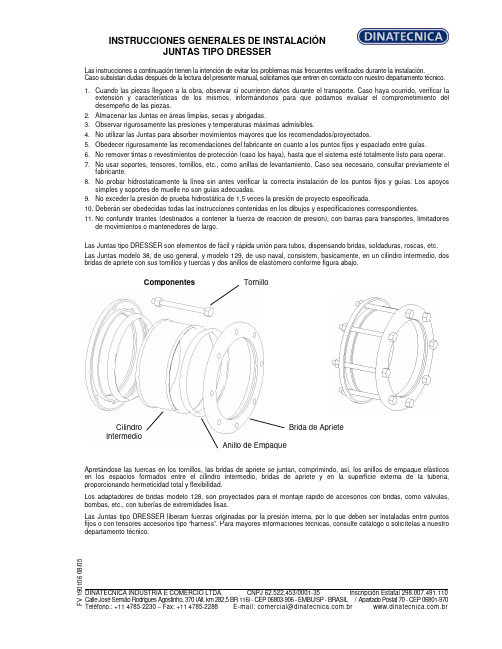
INSTRUCCIONES GENERALES DE INSTALACIÓN JUNTAS TIPO DRESSERLas instrucciones a continuación tienen la intención de evitar los problemas más frecuentes verificados durante la instalación. Caso subsistan dudas después de la lectura del presente manual, solicitamos que entren en contacto con nuestro departamento técnico.1. Cuando las piezas lleguen a la obra, observar si ocurrieron daños durante el transporte. Caso haya ocurrido, verificar la extensión y características de los mismos, informándonos para que podamos evaluar el comprometimiento del desempeño de las piezas.2. Almacenar las Juntas en áreas limpias, secas y abrigadas.3. Observar rigurosamente las presiones y temperaturas máximas admisibles.4. No utilizar las Juntas para absorber movimientos mayores que los recomendados/proyectados.5. Obedecer rigurosamente las recomendaciones del fabricante en cuanto a los puntos fijos y espaciado entre guías.6. No remover tintas o revestimientos de protección (caso los haya), hasta que el sistema esté totalmente listo para operar.7. No usar soportes, tensores, tornillos, etc., como anillas de levantamiento. Caso sea necesario, consultar previamente el fabricante.8. No probar hidrostaticamente la línea sin antes verificar la correcta instalación de los puntos fijos y guías. Los apoyos simples y soportes de muelle no son guías adecuadas.9. No exceder la presión de prueba hidrostática de 1,5 veces la presión de proyecto especificada.10. Deberán ser obedecidas todas las instrucciones contenidas en los dibujos y especificaciones correspondientes.11. No confundir tirantes (destinados a contener la fuerza de reacción de presión), con barras para transportes, limitadores de movimientos o mantenedores de largo.Las Juntas tipo DRESSER son elementos de fácil y rápida unión para tubos, dispensando bridas, soldaduras, roscas, etc. Las Juntas modelo 38, de uso general, y modelo 129, de uso naval, consistem, basicamente, en un cilindro intermedio, dos bridas de apriete con sus tornillos y tuercas y dos anillos de elastómero conforme figura abajo.Componentes Apretándose las tuercas en los tornillos, las bridas de apriete se juntan, comprimindo, así, los anillos de empaque elásticos en los espacios formados entre el cilindro intermedio, bridas de apriete y en la superficie externa de la tubería, proporcionando hermeticidad total y flexibilidad.Los adaptadores de bridas modelo 128, son proyectados para el montaje rápido de accesorios con bridas, como válvulas, bombas, etc., con tuberías de extremidades lisas.Las Juntas tipo DRESSER liberam fuerzas originadas por la presión interna, por lo que deben ser instaladas entre puntos fijos o con tensores accesorios tipo “harness”. Para mayores informaciones técnicas, consulte catálogo o solicítelas a nuestro departamento técnico.F V 190106 08/05 DINATECNICA INDUSTRIA E COMERCIO LTDA. CNPJ 62.522.453/0001-35 Inscripción Estatal 298.007.491.110 Calle José Semião Rodrigues Agostinho, 370 (Alt. km 282,5 BR 116) - CEP 06803-906 - EMBU/SP - BRASIL / Apartado Postal 70 - CEP 06801-970Teléfono.: +11 4785-2230 – Fax: +11 4785-2288 E-mail:*************************.br .brTornilloBrida de Apriete Anillo de EmpaqueCilindro IntermedioINSTRUCCIONES GENERALES DE INSTALACIÓN JUNTAS TIPO DRESSERTipos 38 y 129 ESQUEMA DE MONTAJELimpiar los extremos de los tubos que serán acoplados (aprox.200 mm en cada extremo). Remover completamente cualesquiera oleosidades, rebarbas, salpicaduras de soldadura, etc., de tal forma que los tubos queden limpios y sin ningún saliente que pueda perjudicar el montaje y performance de la Junta. Recomendamos que, después de limpiar los anillos de empaque y, antes del montaje del sistema, sean imersos en una solución de água y jabón (y glicerina, tratándose de temperaturas abajo de 0°C), lo que facilitará el montaje de los mismos.Colocar las bridas de apriete, deslizándolas en el área limpia de los tubos. Posicionar los anillos de empaque cerca de las bridas (uno en cada extremo del tubo).Limpiar bien el cilindro intermedio, poniendo particular atención en los extremos donde asentarán los anillos de empaque. Colocar el cilindro intermedio sobre uno de los tubos terminales.Aproximar el otro terminal hasta conseguir que entre los dos extremos se establezca una holgura de 13mm (tipo 38), y de 13 mm + diámetro del “pipe-stop” (tipo 129). Esta holgura permite la absorción de la dilatación de la línea.Una vez completada la centralización, deslize los anillos de empaque y bridas de apriete contra los extremos (asientos) del cilindro intermedio hasta que se produzca el encaje de los mismos.Insertar los tornillos. Ajustar las tuercas manualmente hasta que se recuesten en las bridas.El apriete final deberá ser dado con dos llaves fijas, una produciendo el torque y otra impidiendo el giro del tornillo.El apriete deberá ser realizado en forma intercalada con fuerza progresiva, hasta conseguir que todos los tornillos tengan un ajuste uniforme. Si en la prueba hidrostática surgiesen escapes, deberá darse un sobre-apriete uniforme, progresivamente, hasta que la prueba presente resultado satisfatório.Cuando haya “pipe-stops”, estos deberán ser retirados antes de la instalación y recolocados después de su finalización.Tipo 128 Deben seguirse los mismos cuidados para los tipos 38 y 129, sin embargo, considerándose que uno de los terminales es parte integrante de la Junta, lo que facilitará su instalación.a) Antes de, eventualmente, modificar cualesquiera de nuestras instrucciones, solicitamos consultarnos. NOTAS: b) Nuestra garantía no cubre daños ocurridos por el incumplimiento de cualesquiera de las recomendaciones aquí expuestas, sin nuestro previo consentimiento.F V 190106 08/05DINATECNICA INDUSTRIA E COMERCIO LTDA. CNPJ 62.522.453/0001-35 Inscripción Estatal 298.007.491.110 Calle José Semião Rodrigues Agostinho, 370 (Alt. km 282,5 BR 116) - CEP 06803-906 - EMBU/SP - BRASIL / Apartado Postal 70 - CEP 06801-970Teléfono.: +11 4785-2230 – Fax: +11 4785-2288 E-mail:*************************.br .br。
快速安装指南(英文)-InstallationGuide
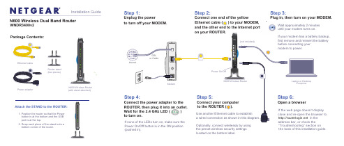
Step 2:Connect one end of the yellowand the other end to the Internet port on your ROUTER.Step 3:Plug in, then turn on your MODEM.Wait approximately 2 minutesuntil your modem turns on.N600 Wireless Router Package Contents:N600 Wireless Dual Band RouterWNDR3400v2Installation GuidePower adapterEthernet cable“Troubleshooting” section on the back of this installation guide.(with stand attached)Power On/Off button is in the ON position (pushed in).Attach the STAND to the ROUTER:1. Position the router so that the Power button is at the bottom and the USB port is at the top.2. Snap each piece of the stand onto a bottom corner of the router.Step 1:Unplug the powerto turn off your MODEM.Optionally, connect wirelessly by using the preset wireless security settings located on the bottom label.Router stand (two pieces)© 2011 by NETGEAR, Inc. All rights reserved. NETGEAR and the NETGEAR logo are registered trademarks of NETGEAR, Inc. in the United States and/or other countries. Other brand and product names are trademarks orregistered trademarks of their respective holders. Information is subject to change without notice.June 2011Find the preset Wireless Settings on your router and record them here:Wi-Fi Network Name (SSID) _______________________________ Network Key (Password ) ________________________________If you change the preset wireless settings, record it here:Connect Wireless Devices to Your RouterChoose either the manual or Wi-Fi Protected Setup (WPS) method to add wireless computers, and other devices to your wireless network.Manual Method1. Open the software utility that manages your wireless connections on thewireless device that you want to connect to your router (iPhone, laptop,computer, gaming device). This utility scans for all wireless networks in your area.2. Look for the preset NETGEAR wireless network name (SSID), and select it.The preset Wi-Fi network name (SSID) is located on the product label on the bottom of the router.Note: If you changed the name of your network during the setup process, look for that network name.3. Enter the preset password (or your custom password if you changed it), andclick Connect .4. Repeat steps 1–3 to add other wireless devices.WPS MethodIf your wireless device supports WPS (Wi-Fi Protected Setup)—NETGEAR calls this method Push 'N' Connect—you might be prompted to press the WPS button on the router instead of entering a password. If this happens:1. Press the WPS buttonon the router.2. Within 2 minutes, press the WPS button on the client device, or follow theWPS instructions that came with your wireless device to complete the WPS process. The device will then be connected to your router. 3. Repeat this process to add other WPS wireless devices.Note: WPS does not support WEP security. If you try to connect a WEP client to your network using WPS, it will not work.TroubleshootingThe browser cannot display the Web page.• Make sure that the PC is connected to one of the four LAN Ethernet ports, orwirelessly to the router.• Make sure that the router is fully up and running. Its wireless LED should turnon.• Close and re-open the browser to make sure that the browser does not cachethe previous page.• Browse to .• If the PC is set to a static or fixed IP address (this is uncommon), change it toobtain an IP address automatically from the router.Other FeaturesFor complete DoC please visit the NETGEAR EU Declarations of Conformity website at: /app/answers/detail/a_id/11621.For GNU General Public License (GPL) related information, please visit /kb_web_files/open_src.asp .For additional features, including Live Parental Controls, Traffic Metering, ReadyShare, Guest Access, and others, please log into your router at .Download the free NETGEAR Genie Automatically fix common network problems and easily manage your home network connections./genie。
INFICON-I O1000-I O-模块-快速安装指南说明书

Quick-start installation guide for I/O1000 I/O module Safety instructionsThis quick-start guide does not replace the installation manual for the I/O1000 I/O module. Safe use of the module is ensured only by reading the installation manual.Additional important information is provided in the installation manual for the I/O1000 I/O module. The manual can be found either on the USB memory stick or on the INFICON website. The USB memory stick is included with the shipment of the I/O module.Intended useThe I/O module is a device interface between the MSB box of the mass spectrometer module LDS3000 and an external controller, for example.►Install, operate and service the unit only in compliance with the installation manual.►Comply with the limits of application.User requirements►Operate and install the unit only if it is in perfect working order and as intended, in a safety-conscious manner and fully aware of dangers, in compliance with this manual.►Fulfill and ensure compliance with the following regulations:–Intended use–Generally applicable safety and accident prevention regulations–International, national and local standards and guidelines–Additional provisions and regulations that are specific to the unit►Use only original parts or parts approved by the manufacturer.►Keep the installation manual available at the operating site.►All work must be performed only by technical specialists who have been trained on the unit.►Allow personnel in training to work with the unit only under the supervision of technical specialists.►Make sure that the authorized personnel have read and understood this manual and all otherapplicable documents, especially the information on safety, maintenance and repairs, before starting work.►Define responsibilities, authorizations and supervision of personnel.User requirements►Read, observe and follow the information in the installation manual and the working instructionscreated by the owner, especially the safetyinstructions and warnings.►Perform all work based on the complete manual.Document: jima10en1-03 (1503)Mounting of I/O module✗DIN-TS35 top hat rail1Hook unit on top hat rail at bottom.2Press unit onto top hat rail at top.Connecting I/O module with leak detectorThe I/O module communicates via data cable with the leak detectorand is supplied with voltage by the data cable.✗Data cables from INFICON1Connect I/O module (connection LD) via data cable with leak detector.2Connect I/O module via desired interfaces with external controller:•RS232 (RS-232 interface)•RS485 (RS-485 interface)•A NALOG I N (analog input)•A NALOG O UT (analog outputs)•P LC I N (digital inputs)•P LC O UT (digital outputs)Description of the layoutsee Installation Manual for I/O module, jiqc10.FUSE and DIP switch S1, S2fFuses for digital outputs and DIP switches (under the cover)Fuses for digital outputs 1...4 and 5...8:2x0.75A (Schurter: 7010.9800.xx)1 = ON, 0 = OFF1 = ON, 0 = OFF, + = switching from OFF to ON during operation,X = randomFig: 1Mount I/O module on DIN-TS35 top hat rail Fig: 2Rear view of I/O module1PLC IN2RS2323STATUS4ANALOG OUT 5PLC OUT 6S1, S2 and FUSE 7LD8ANALOG IN9RS4851024V OUT DIP switch S1LDS3000HLD6000Contact4321 Factory setting (defaultvalue of the interfaceprotocol by the leakdetector or control unit)∙∙0000ASCII protocol∙∙0010 LD protocol∙∙0011 Binary protocol∙0101 LDS1000 protocol∙0110 Normal protocol∙0001 Simple protocol∙0100DIP switch S2Contact4321 Activate boot mode for software update X+00 Disable bus terminator 120Ω for RS-4851X00INFICON GmbH, Bonner Strasse 498, D-50968 Cologne, GermanyVisit our website for contact information and other sales offices worldwide. Document: jima10en1-03 (1503)。
Woovi for Magento 2.x 插件安装指南说明书

Woovi For Magento Installation GuideThe plugin Woovi handles an instant payment method in Brazil.So,when installing the plugin Woovi you need to have an active account inside our platform.You can open a new Woovi account by the linkhttps:///registerWith the account on you will be able to:-Create a new AppID to be used with this plugin-Create a new webhook to listen when the order is paid and update it on the Magento2platformConfiguring the plugin on Magento2Once the plugin is installed follow the steps below to configure it.First,let's configure the credentials starting with the plugin appID.1.Generate a new appID following our documentationhttps:///docs/plugin/app-id1.Go to Admin->Stores->Configuration->Payment Methods2.Look for the Woovi group:3.Fill the appID with the appID generated on the Woovi platform.TheApp ID is acquired on the Woovi side.If you can generate it by thedocumentation call the support to help you to get it.4.Save it.Configuring the webhookThe webhook is configured automatically.Just click on Configure now with one click.But,it is important to have the appID already configured and saved!If the configuration is ok the Webhook Status must be Configured.Configuring the payment1.Enable the payment2.Choose the new order status3.Choose your payment title4.Save the configurationUsing the payment methodOnce everything is configured you will be able to see the configuration option on the checkout payment step.When generating the payment with Woovi your checkout success must look like the following image:Order DetailYour customer is able to see his Pix Qrcode inside the order detail。
Hook和Key用于Mini 60的安装指南说明书
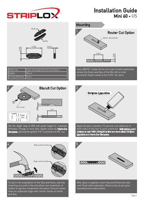
Page 2
5
Align centre marks
To aid in the installation of the Key and Hook, start by inserting one end in the slot when use a hammer or mallet to tap the component into place. Ensure center lines on substrate align with center marks on Hook and Key.
3
Striplox Liquidlox
0.276
Set the depth stop to #20 and guide height for substrate thickness. Plunge in once then repeat using the Mark-Out Template, packing the guide 0.118” to achieve a 0.276” cut.
Assembly components remembering the Key only needs to travel 1 pitch for full engagement. This is detailed in steps A anlign Marks
Note the offset of the lugs on the Key body, length X is larger than Y. Insert the Hook into the Key with the longer X end towards the face to be pushed during assembly.
- 1、下载文档前请自行甄别文档内容的完整性,平台不提供额外的编辑、内容补充、找答案等附加服务。
- 2、"仅部分预览"的文档,不可在线预览部分如存在完整性等问题,可反馈申请退款(可完整预览的文档不适用该条件!)。
- 3、如文档侵犯您的权益,请联系客服反馈,我们会尽快为您处理(人工客服工作时间:9:00-18:30)。
工作流引擎项目文档工作流引擎安装手册-- 1 ---- 2 --目 录1. 文档版本 ............................................................................................................................................................ 32. 词汇总表 ............................................................................................................................................................ 43. 撰写目的 ............................................................................................................................................................ 54. 阅读对象 ............................................................................................................................................................ 55. 参考文档 ............................................................................................................................................................ 56.检索信息 (6)6.1. 摘要 (6)6.2.关键词 (6)7.文档正文 (6)1.文档版本文档更改历史记录文档编号001-000【说明】✧文档编号格式组织代码-项目代码-文档类别编码-文档顺序号(三位数字)✧文档类别编码BIZ : 业务需求描述文档 (BUISNESS)FUC : 功能需求描述文档 (FUNCTION)ARC : 构架体系描述文档 (ARCHITECTURE)ISA : 系统实现SA文档 (概要设计文档)ISD : 系统实现SD文档 (详细设计文档)ICD : 系统实现CD文档 (系统实现代码描述文档)UDC :系统用户使用手册✧版本描述主版本号(三位数字)-次版本号(三位数字)-- 3 --2.词汇总表-- 4 --3.撰写目的描述文档的撰写目的4.阅读对象描述文档的预期阅读对象5.参考文档文档涉及的参考文档列表-- 5 --6.检索信息6.1.摘要6.2.关键词7.文档正文1WILLOW作为独立的工作流引擎服务器1.1安装后目录视图1.2安装步骤1.2.1安装工作流引擎WILLOW还是采用ZIP格式进行发布的,用户下载安装文件后,解开压缩文件即可。
文档中假设用户安装WILLOW引擎服务器的目录为WILLOW_HOME(图中为D:\project\willow)。
(1)解开压缩文件,用户将看到类似上图的目录结构形式。
(2)建立引擎需要的数据结构。
用户下载对应数据库类型的数据库脚本文件。
随引擎发布的数据库脚本只有Oracle和Mysql版本的,从理论上讲只要数据库提供标准的JDBC2.0实现,都可以被引擎支持。
其他数据库类型的引擎数据接口脚本只需要拷贝一份ORACLE数据库安装脚本,进行针对本地化数据支持的数据类型进行调整就可以了。
(3)建立引擎自带的测试流程需要的数据结构。
用户下载对应数据库类型数据库脚本文件,在步骤(2)运行成功之后运行相应脚本即可。
-- 6 --1.2.2配置工作流引擎(1)工作流引擎目录列表一个工作流应用系统是由一个或者多个流程组成(对应一个或者多个XPDL流程描述文件)。
而一个工作流应用系统对应于工作流引擎应用程序目录(repository)下面一个目录。
下面就引擎发布版本自带的测试工作流应用系统进行描述。
-- 7 ---- 8 --(3) 配置工作流引擎整合TOMCA T 提供JSP/SERVLET 支持WILLOW 默认提供对TOMCA T 整合以便提供JSP/SERVLET 功能,默认的TOMCA T 安装目录是${WILLOW_HOME}/catalina ,如果用户需要安装在其他目录,需要修改${WILLOW_HOME}/bin/willow-with-catalina.bat 指向对应用户提供的安装目录。
脚本最后有这样的描述:(为了阅读方便,进行了分行处理,实际上是在同一行上) %_EXECJA V A%%JA V A_OPTS% %WILLOW_OPTS%-Djava.endorsed.dirs="%JA V A_ENDORSED_DIRS%" -classpath "%CLASSPA TH%"-Dwillow.home="%WILLOW_HOME%"-Dwebserver.factory=org.huihoo.willow.tomcat.TomcatServer -Djava.io.tmpdir="%WILLOW_TMPDIR%" %MAINCLASS%%CMD_LINE_ARGS%%ACTION%如果TOMCA T 不是默认安装目录,需要使用-Dcatalina.home=XXXX 形式传递参数,比如用户TOMCA T 安装目录是F:\catalina5,上面对应行内容应该为: %_EXECJA V A% %JA V A_OPTS% %WILLOW_OPTS%-Djava.endorsed.dirs="%JA V A_ENDORSED_DIRS%" -classpath "%CLASSPA TH%" -Dwillow.home="%WILLOW_HOME%" - Dcatalina.home=" F:\catalina5"-Dwebserver.factory=org.huihoo.willow.tomcat.TomcatServer -Djava.io.tmpdir="%WILLOW_TMPDIR%"-- 9 --%MAINCLASS%%CMD_LINE_ARGS%%ACTION%需要注意的是不管用户是否定制TOMCA T 安装目录,引擎如何整合TOMCA T 运行, TOMCA T 配置文件都是${WILLOW_HOME}/conf/catalina.xml ,进行上面的步骤之后都需要修改${WILLOW_HOME}/conf/catalina.xml 使得<Host name="localhost" debug="0" appBase="D:/project/willow/repository">配置指向正确的应用程序安装目录,以便工作流引擎装载工作流应用系统。
(4) 配置工作流引擎数据库访问链接信息请修改${WILLOW_HOME}/conf/store.properties ,修改对应的数据库链接信息。
(5) 启动工作流引擎2WILLOW 作为单独的JAR 文件进行部署WILLOW 默认提供两种访问模式,一种是基于本地对象系统的访问,另外一种是基于RMI 的访问。
基于本地对象系统的访问是 WILLOW 工作流引擎核心组间功能,而RMI 访问方式用户是可以根据需要进行定制(定制是指 需要启动服务还是取消启动服务)。
方便用户部署,WILLOW 工作流引擎也支持类似soap/struts 基于jar 文件的部署方式。
基于jar 部署步骤很简单,用户按照如下步骤进行即可:(1) 将工作流引擎需要的jar 或者class 文件拷贝到你需要的WEB 应用程序WEB-INF 对用目录下。
(2) 修改 web.xml 以便需要的时候能启动工作流引擎。
<servlet> <servlet-name>WorkflowServlet</servlet-name> <servlet-class>org.huihoo.willow.deploy.WorkflowServlet</servlet-class> <init-param> <param-name>WILLOW_HOME</param-name><param-value>C:\ Tomcat 5.0\webapps</param-value></init-param><init-param> <param-name>WILLOW_CONFIG</param-name> <param-value> WEB-INF/willow-server.xml</param-value> </init-param><init-param> <param-name>WILLOW_STORE</param-name><param-value> WEB-INF/willow-store.properties</param-value> </init-param><init-param>-- 10 --<param-name>WILLOW_DA TABASE</param-name><param-value>WEB-INF/willow-database.xml</param-value></init-param><load-on-startup>1</load-on-startup></servlet><servlet-mapping><servlet-name>WorkflowServlet</servlet-name> <url-pattern>/willow</url-pattern> </servlet-mapping>到这里作为单独jar 部署工作流应用就完成了,用户需要的真是修改一些配置文件进行工作流引擎定制处理。
