AEC模温机使用手册
模温机操作说明
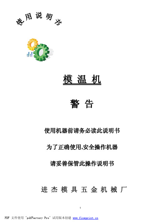
模温机警告使用机器前请务必读此说明书为了正确使用,安全操作机器请妥善保管此操作说明书进杰模具五金机械厂模温机微电脑控制器操作说明注:要使用本控制器前必须祥细阅读本操作说明一、正面视图及背面接线图:(正面视图)(背面接线图)http// 电话0755-******** 传真0755-********1.指示灯说明:水泵------------(在任何状态下)当水泵继电器吸合时灯就会亮,断开时灯就灭。
(包括在A T运行时)加热------------(在任何状态下)当加热继电器吸合时灯就会亮,断开时灯就灭。
(包括在A T运行时)冷却------------(在任何状态下)当冷却继电器吸合时灯就会亮,断开时灯就灭。
(包括在A T运行时)过载------------当系统检测到有水泵过载信号输入时,灯就会亮,反之则不亮。
(包括在A T运行时)缺水------------当系统检测到有缺水信号输入时,灯就会亮,反之则不亮。
(包括在A T运行时)超温------------当系统检测到有超温信号输入时,灯就会亮,反之则不亮。
(包括在A T运行时)断偶------------当系统检测到有断偶信号输入时,灯就会亮,反之则不亮。
(包括在A T运行时)逆相------------当系统检测到有逆相信号输入时,灯就会亮,反之则不亮。
(包括在A T运行时)2.按键说明:ON/OFF-------是开关机按键HEA T----------加热关闭/开启键TEMP/TIME----是温度/定时时间转换键AUTO------------自动运行键(需要时)ENT---------------参数确认/翻面键ADD--------------参数增加键SUB---------------参数减小键SET---------------参数层进入/退出键3.故障输入说明:超温故障输入---------常闭触点信号,断开为故障,接通为正常水泵故障输入---------常开触点信号,接通为故障,断开为正常缺水故障输入---------常开触点信号,接通为故障,断开为正常逆相故障输入---------常闭光偶信号,光偶不导通为故障,导通为正常断偶故障输入---------当出现感温线断路时,就为故障4.输出说明:12V蜂鸣器输出-------在操作按键时和在有报警输出时,蜂鸣器都要鸣叫,报警输出时要作通断输出。
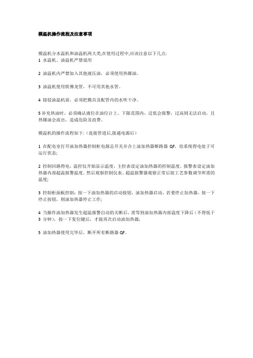
模温机操作流程及注意事项
模温机操作流程及注意事项
模温机分水温机和油温机两大类,在使用过程中,应该注意以下几点:
1 水温机、油温机严禁混用
2 油温机内严禁加入其他液压油,必须使用热媒油。
3 油温机使用铁佛龙管,不可用其他水管。
4 接驳油温机前,必须把模具及配管内的水吹干净。
5补充热油时,必须确认液位在油位计上、下限范围内,过低会报警,过高则无法启动,且热媒油会流出,造成危险及浪费。
模温机的操作流程如下:(连接管道后,接通电源后)
1 在配电室打开油加热器控制柜电源总开关并合上油加热器断路器QF,给系统得电处于可运行状态;
2 控制回路得电,温控仪开始显示温度,主控表设定油加热器的控制温度。
报警表设定油加热器内部超温报警温度。
然后观察控制仪表、超温报警器观察正常后按工艺参数调节所需的温度;
3 控制柜面板控制:按一下油加热器的启动按钮,油加热器启动,若要停止加热器,按一下停止按钮,则油加热器停止工作;
4 当操作油加热器发生超温报警自动的关断后,需等到油加热器内部温度下降后(不得低于3 分钟),按一下复位键后,才能再次启动油加热器;
5 油加热器使用完毕后,断开所有断路器QF。
AEC ECU100 模温机说明书
AEC ECU100 模温机使用手册——NICK.SUN Page 8 of 22
设备部
5-3 启动机器 打开供水,打开电源,按 ON/OFF 键到 ON 的位置。 机器自动运行 1 分钟的排气程序,以模具排除管路中的空气。AEC 建议在大型模具上延长
重要点!
在未知会 AEC 服务人员前,请不要改变任何控制设定。 AEC 的质保不包括由于控制设定窜改造成的机器损坏!
向下键 每按一次向下键,可以使显示的设定值减小。
向上键 每按一次向上键,可以使显示的设定值增加。
AEC ECU100 模温机使用手册——NICK.SUN Page 5 of 22
设备部
注意:需专业电气人员进行下面的工作。 改变转向: 1. 切断电源。 2. 交换电源进线接线端的 2 个线头。 3. 不要改变马达或马达接触器的接线。 5-7 关闭温度控制器 选择温度设定为零。让机器的温度接近进水的温度,然后按 STOP 键。按 VENT 键开始降 低系统中保持的压力。
6 维护 6-1 预防性维护
整。如果控制器不能正确工作,或有人意外地更改了某些设定,你可以做下面两件事。首先,执 行自动整定程序。如果不能运行,重置工厂的原始设定。 4-8 控制器内部开关
因为工厂已经进行了设定,所以不必再调整内部开关。如果控制器不能正确工作,或有人 意外地更改了某些设定,你可以做下面两件事。首先,执行自动整定程序,见 4-10。如果不能 运行,重置工厂的原始设定,见 6-3。 4-9 控制器的工厂设定
AEC ECU100 模温机使用手册——NICK.SUN Page 11 of 22
设备部 E5CK 的几种模式
菜单显示 λ LEVEL 0 模式 可进行一般的操作。可执行 AT 自动整定,切换至手动方式。 λ LEVEL 1 模式 可调整初级控制参数。可执行:设置告警值;设置控制周期;设置 PID 参数。 λ LEVEL 2 模式 可调整二级控制参数。经济型 TCU 机器使用 E5CK 的默认设定。 λ SETUP 模式 可设置基本的特性参数。设置输入类型(指热电偶类型),单位,输出分 配和正反向控制。 λ 扩展模式 可设置扩展功能。可设置:ST(自整定),SP 设定极限。可选择:PID 优 先控制或通断控制。 λ 附加模式 这个模式仅当机器安装有附加功能板时才有效。 λ 校正模式 用于校正 E53-CKF。本机无效。
模温机安全操作规程

模温机安全操作规程一、目的本安全操作规程的目的是确保模温机的安全运行,防止事故发生,保护操作人员的人身安全和设备的正常运行。
二、适合范围本安全操作规程适合于所有使用模温机的操作人员。
三、安全操作规程1. 模温机的安装1.1 模温机应安装在通风良好、无火源和易燃物的场所。
1.2 模温机的电源应接地可靠,电源线应符合国家标准,并定期检查电源线的状况。
1.3 模温机的冷却管路应与冷却水源连接,并确保冷却水的流量和温度符合设备要求。
2. 模温机的操作2.1 操作人员应事先了解模温机的基本原理和操作方法,并接受相关培训。
2.2 在操作模温机前,应检查设备的电源、冷却水和温度控制系统是否正常工作。
2.3 操作人员应佩戴适当的防护设备,如安全眼镜、防护手套等。
2.4 在操作模温机时,应按照设备的操作说明进行操作,并严禁超负荷运行。
2.5 操作人员应定期检查模温机的温度控制系统,确保温度控制精度和稳定性。
3. 模温机的维护3.1 模温机应定期进行维护保养,包括清洁设备、检查电气路线、润滑传动部件等。
3.2 维护人员应具备相关技术知识和操作经验,并按照设备创造商的要求进行维护。
3.3 维护过程中,应切断电源,并确保设备处于停机状态。
3.4 维护人员应定期检查模温机的冷却水系统,清洗冷却水管路,防止阻塞和生物污染。
4. 模温机的紧急处理4.1 在模温机发生故障或者异常情况时,操作人员应即将切断电源,并报告相关人员进行处理。
4.2 在模温机发生火灾时,应即将启动灭火装置,并迅速撤离人员,保持安全距离,等待消防人员的到来。
4.3 在模温机发生泄漏时,应采取措施防止泄漏物进入地下水或者其他环境中,并及时清理泄漏物。
四、应急预案1. 制定模温机的应急预案,明确各种紧急情况下的处理措施和责任人。
2. 定期组织演练,提高操作人员的应急处理能力和反应速度。
3. 在发生事故后,及时总结教训,完善应急预案,以提高应对突发情况的能力。
模温机操作说明书
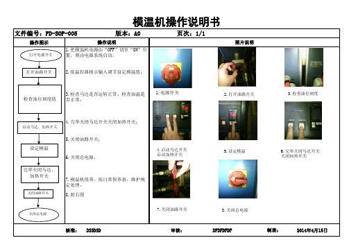
操作图示核准:DSSDSD 审核:DFDFDFDF 2014年4月15日制表: 4.完单关闭马达开关关闭加热开关;
5.关闭油路开关;
6.关闭总电源;
8.附右图7.模温机保养,依日常保养表,维护规
定处理。
3.检查马达是否运转正常、检查油温是
否正常;模温机操作说明书
操作说明图片说明文件编号:PD-SOP-005
版本:A0页次:1/11.把模温机电源由“OFF”切至“ON”位置,则由电源系统启动;
2.依温控器指示输入调节设定模温值;检查油位刻度值 打开电源开关 打开油路开关
启动马达、加热开关
完单关闭马达、
加热开关 关闭油路开关 关闭总电源
设定模温
2.打开油路开关 4.启动马达开关 启动加热开关 5.设定模温
3.检查油位刻度
1.电源开关 6.完单关闭马达开关关闭加热开关 7.关闭油路开关 8.关闭总电源。
模温机使用说明
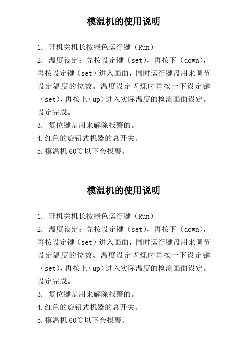
模温机的使用说明
1. 开机关机长按绿色运行键(Run)
2. 温度设定:先按设定键(set),再按下(down),再按设定键(set)进入画面,同时运行键盘用来调节设定温度的位数。
温度设定闪烁时再按一下设定键(set),再按上(up)进入实际温度的检测画面设定。
设定完成。
3. 复位键是用来解除报警的。
4.红色的旋钮式机器的总开关。
5.模温机60℃以下会报警。
模温机的使用说明
1. 开机关机长按绿色运行键(Run)
2. 温度设定:先按设定键(set),再按下(down),再按设定键(set)进入画面,同时运行键盘用来调节设定温度的位数。
温度设定闪烁时再按一下设定键(set),再按上(up)进入实际温度的检测画面设定。
设定完成。
3. 复位键是用来解除报警的。
4.红色的旋钮式机器的总开关。
5.模温机60℃以下会报警。
模温机说明书

模温机说明书全文共四篇示例,供读者参考第一篇示例:模温机是一种用于塑料、橡胶等材料加工中控制温度的设备。
它主要由加热系统、冷却系统、温度控制系统和传动系统等组成。
模温机的作用是在制造过程中保持模具和材料的温度恒定,以确保成品的质量和生产效率。
一、模温机的工作原理模温机通过加热系统和冷却系统来控制模具和材料的温度。
当模具需要加热时,加热系统会向模具传送热能,使模具温度升高;当模具需要冷却时,冷却系统会向模具传送冷却剂,使模具温度降低。
模温机通过温度控制系统监测模具的温度,并根据需要调节加热和冷却系统的工作,以保持模具温度稳定在设定值。
二、模温机的特点1. 高效节能:模温机具有快速加热和冷却的特点,可以大大提高生产效率,减少能源消耗。
2. 精确控温:模温机配有高精度的温度控制系统,可以精确控制模具和材料的温度,确保制品的质量。
3. 操作简便:模温机的操作界面简单直观,操作起来方便快捷,可以减少人为操作错误。
4. 多种保护功能:模温机配有过载保护、短路保护等多种安全保护功能,确保设备运行稳定安全。
三、模温机的应用领域模温机广泛应用于塑料注塑、吹塑、压延、挤塑、橡胶加工等领域。
在这些领域中,模温机可以为生产企业提供稳定的温度控制,提高产品质量,降低生产成本。
四、模温机的维护保养1. 定期清洗:模温机在使用过程中会有灰尘和杂质堆积,需要定期清洗。
清洗时应注意断开电源,防止发生意外。
2. 定期检查润滑油:模温机的传动系统需要使用润滑油,定期检查润滑油的情况并及时更换。
3. 定期维护:模温机的各个部件需要定期检查和维护,确保设备的正常运行。
五、模温机的使用注意事项1. 使用前请仔细阅读说明书,并按照操作步骤正确操作。
2. 在使用过程中请勿随意更改设备设置,以免影响设备的正常运行。
3. 使用过程中如发现异常情况,请及时停机检查,确保设备安全运行。
第二篇示例:模温机是一种用于温度控制的设备,通常被广泛应用于塑料工业、机械加工行业和医疗器械制造等领域。
AECH-11温湿度控制器说明书

AECH-11温湿度控制器说明书
1、接线,通电后,红色指示灯亮,满足加热条件时绿灯亮,表示加热器工作。
2、按下面板上“测试”按钮可进行强制加热,同时可检查加热器是否断线。
加热时如发现断线,绿灯亮,报警输出接点闭合。
“测试”是自锁按钮,除在需要强制加热时按下,一般在平时运行时请将“测试”按钮置于弹出位置。
3、如需试验凝露感湿后的加热工作情况,在温度>20OC 环境中,可将湿度传感器放入冰箱约5分钟后取出,来模拟凝露条件,或用对湿度传感器哈气的方法进行,观察凝露条件下的工作情况。
4、安装时注意保护传感器及接线,以免松动造成控制器不能正常工作。
模温机操作规程
模温机操作规程一、目的和适用范围本操作规程的目的是确保模温机的安全运行和正确操作,以提高生产效率和产品质量。
适用于所有使用模温机的操作人员。
二、安全注意事项1. 在操作模温机前,必须穿戴好个人防护装备,包括安全帽、防护眼镜、防护手套和安全鞋。
2. 在操作过程中,严禁戴手套或衣袖进入机器内部,以防止被夹伤。
3. 操作人员必须熟悉模温机的工作原理和操作方法,严禁未经培训或未经授权的人员操作模温机。
4. 在操作模温机前,必须检查电源插头和电源线是否完好,确保接地良好,避免电击事故发生。
5. 操作人员必须保持机器周围的清洁和整洁,避免杂物堆积和阻塞通风口。
6. 操作人员在调节温度时,应逐渐调整,避免温度过高或过低,以免影响生产和设备寿命。
三、操作步骤1. 打开模温机的电源开关,并确保温度控制器处于关闭状态。
2. 检查模温机的水箱水位,确保水位在合适范围内,如不足应及时添加冷却水。
3. 操作人员根据生产需要,设置所需的温度值和时间参数,确保温度控制器设定正确。
4. 打开模温机的启动开关,待机器运行正常后,逐步调节温度控制器,使温度逐渐达到设定值。
5. 在模温机运行过程中,操作人员应定期检查温度控制器的显示数值,确保温度稳定在设定值附近。
6. 当需要停止模温机时,先将温度控制器的设定值调至最低,然后关闭模温机的启动开关和电源开关。
7. 操作人员在操作完毕后,应将模温机周围的工作区域清理干净,并关闭冷却水阀门。
四、故障处理1. 如果模温机出现异常报警或故障,操作人员应立即停止使用,并通知维修人员进行检修。
2. 在维修人员到达之前,操作人员应将模温机的电源开关关闭,并将故障情况详细记录,以便维修人员进行准确的排查和修复。
五、维护保养1. 定期清洁模温机的外壳和散热器,保持良好的散热效果。
2. 定期检查模温机的电源线和插头,确保无损坏和松动现象。
3. 定期检查模温机的水箱和水泵,确保水流通畅,并及时更换冷却水。
4. 定期检查模温机的温度控制器和传感器,确保准确可靠。
模温机操作说明
模温机操作说明
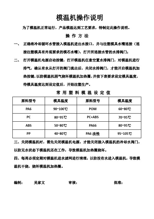
为了模温机正常运行,产品模温达到工艺要求,特制定此操作说明。
操作方法
一、正确将冷却循环水管接入模温机进出水接口,并与注塑模具水嘴连接(连
接注塑模具有外观要求的模芯水嘴),打开所连接水管的水排阀门;
二、打开模温机电源启动按键,打开模温机任意空置水排阀门,对模温机进行
排气,确认有水从打开的阀门流出后,关闭水排阀门,才能开启模温机加热按键,以防模温机困气烧坏模温机加热圈,并按下表要求设定模具温度,待模具温度达到设定值后,开始注塑生产。
常用塑料模温设定值
三、关闭模温机时,需先关闭模温机电源,才能关闭接入模温机的冷却水阀门,以防无水状态下模温机还在工作,导致模温机加热圈烧坏。
四、每周必须定期对模温机进水滤网进行清理,以防没有水进入模温机,导致模温机干烧,烧坏模温机加热圈。
编制:吴家文审核:批准:。
模温机操作指导书

模温机操作指导书
《模温机操作指南》
嘿,朋友们!今天咱来聊聊模温机的操作那些事儿。
模温机这家伙,就像是个贴心的小助手,能帮咱把好多事情都料理得妥妥当当。
但要想让它乖乖听话,好好干活,那可得知道怎么摆弄它。
先说说开机吧。
就像咱早上起床要先睁开眼睛一样,模温机要启动也得有个步骤。
找到那个电源开关,轻轻一按,看着指示灯亮起来,就好像模温机打了个哈欠,开始准备工作啦。
然后呢,就是设置温度啦。
这可得仔细着点,就像咱做饭放盐一样,多了少了都不行。
根据你的需要,把温度调好,模温机会努力保持这个温度,就像咱冬天想让屋里一直暖和一样。
模温机工作的时候,咱也别闲着呀。
时不时去看看它,就像关心咱的好朋友一样。
看看温度是不是正常呀,有没有啥异常情况呀。
要是发现有点不对劲,赶紧处理,可别等出了大问题才着急。
还有哦,模温机也需要休息呢。
就像咱累了要睡觉一样,别让它一直不停地工作。
该关机的时候就关机,让它也能喘口气。
有一次我就犯了个小糊涂,设置温度的时候没仔细看,结果温度设高了。
哎呀,那可把我急坏了,赶紧调整过来,还好没出啥大问题。
从那以后呀,我每次操作模温机都格外小心,可不敢再犯同样的错误啦。
总之呢,模温机操作不难,但也得用心。
把它当成咱的好伙伴,好好照顾它,它也会好好帮咱干活。
咱要细心、耐心,这样才能和模温机愉快地合作呀。
希望大家都能熟练掌握模温机的操作,让它为我们的工作带来更多的便利和效率。
模温机操作规程及注意事项
模温机操作规程及注意事项以下是 6 条关于“模温机操作规程及注意事项”:1. 嘿,操作模温机可不像煮个鸡蛋那么简单哟!每次启动前,你得像检查宝贝一样仔细检查设备是否正常。
就好比你要出门,不得先看看钥匙带没带呀!要确保各个管道连接牢固,电气部分没有问题。
要是马虎一下,哎呀,那麻烦可就大啦!一定要认真对待,懂了不?2. 模温机运行时,千万别乱动乱调啊!这就好像你在开汽车,不能瞎摆弄方向盘不是。
要时刻关注温度和压力的变化,就跟关注你的手机电量似的。
要是发现异常,赶紧采取措施呀,别等出了大问题才后悔莫及呀,难道不是吗?3. 注意啦,给模温机添加介质的时候,可得小心谨慎哦!这就好比给病人打针,得精准无误呀。
得按照规定的型号和量来添加,千万别搞错啦。
不然机器出了故障,那可不好玩儿啦,对不对呀?4. 模温机在工作过程中,也得好好照顾它呀!就像照顾你家的宠物一样。
定期清理过滤器,让它呼吸顺畅。
要是不清理,那可不就像人被堵住鼻子一样难受嘛!所以千万别忘了这个重要的步骤哦!5. 哎呀呀,模温机的停机操作也很关键呢!可不是随便一关就了事啦。
要先逐步降低温度,就像你慢慢减速停车一样。
然后再关闭电源,不能太粗暴啦。
不然它也会“发脾气”的哟,到时候可就有你好受的啦,你说是不是呀?6. 最后啊,一定要记住,模温机是个很重要的设备,我们要像对待好朋友一样对待它!只有这样,它才能好好为我们工作呀。
所以在操作和维护它的时候,多上点心,别偷懒哦。
相信只要大家认真对待,模温机就能一直乖乖听话,为我们好好服务的啦!我的观点结论:模温机的操作规程和注意事项必须牢记于心,严格遵守,才能确保其安全稳定运行,为我们的工作带来便利和效益。
模温机操作规程
模温机操作规程引言概述:模温机是一种用于控制模具温度的设备,广泛应用于塑料加工、注塑成型、橡胶制品等行业。
正确操作模温机可以提高生产效率、保证产品质量、延长设备寿命。
本文将详细介绍模温机的操作规程,包括开机准备、设定温度、操作注意事项、关机维护等内容。
一、开机准备1.1 清洁检查:在开机前,应检查模温机的外部是否有杂物,清除可能影响设备正常运行的障碍物。
同时,检查冷却水管道是否畅通,确保冷却系统正常工作。
1.2 电源连接:将模温机的电源线正确接入电源插座,并检查电源线是否有损坏或者短路情况。
确保电源连接坚固可靠,避免电器故障引起安全事故。
1.3 导热介质添加:根据生产需要,选择适当的导热介质,并将其加入模温机的导热介质箱中。
注意导热介质的质量和纯度,避免杂质对设备和产品的影响。
二、设定温度2.1 温度设定:根据生产工艺要求,合理设定模温机的温度。
可以通过模温机面板上的温度调节器进行设定,或者通过连接的计算机软件进行远程设定。
确保设定温度准确无误。
2.2 温度控制:设定温度后,模温机将自动启动加热或者冷却系统,控制模具温度在设定范围内。
在温度控制过程中,应注意观察温度变化情况,及时调整设定值或者操作参数,保持温度稳定。
2.3 温度监测:使用温度传感器等设备对模具温度进行实时监测,确保温度控制的准确性。
如发现温度异常或者超出设定范围,应及时采取措施进行调整或者修复,避免影响产品质量。
三、操作注意事项3.1 安全操作:在操作模温机时,应穿戴好个人防护装备,如安全帽、防护眼镜、防护手套等。
避免因操作不当导致的人身伤害或者设备故障。
3.2 温度调整:在调整模温机温度时,应缓慢调整,避免温度快速变化对模具和产品产生不利影响。
同时,应注意温度调整的平稳性和连续性,避免温度波动过大。
3.3 维护保养:定期对模温机进行维护保养,包括清洁设备、检查电路、润滑部件等。
及时处理设备故障,避免故障扩大和影响生产。
四、关机维护4.1 温度降低:在关机前,应将模温机温度逐渐降低,避免蓦地降温对设备和产品产生不利影响。
模温机操作规范
模温机操作规范
开机前准备
1、检查铁氟隆管与模具的接口是否连接紧密,PT100温度传感器连接是否完全。
2、检查进口、出口、以及与模具连接的球阀是否打开。
(没有接管子的球阀要关闭。
)
3、检查总进水口是否打开,且观察有无水流流过。
4、检查气泵是否能正常工作,查看压力表读数,压力14公斤。
5、检查排气口是否连接到冷水管或是室外安全地带。
6、检查气源处理器的压力是否正确。
大的气源处理器11—12公斤,小的气源处理器5公
斤。
开机事项
1、三相电源拆卸后,要先确定电机的旋转方向。
方向正确才能开机。
2、开机时先把总开关合上,关上配电箱门锁上,机器运转时严禁打开配电箱门。
3、启动设备,待增压泵运转后用手动方式运行进热水、吹热水、进冷水、吹冷水,查看管
道接口有无渗漏现象。
发生渗漏时要停机,重新安装管道或接口,然后继续开始。
无渗漏则退出手动方式。
关机事项
1、需要关机时要在循环结束之后才能关闭设备。
2、关机之后要将总进水口的球阀关闭。
3、关机之后要将进口、出口、以及与模具连接的球阀关闭。
4、将气泵的阀门关闭,通过气源处理器把管道里残留的气体排尽。
5、在下模时要先拆卸PT100和铁氟隆管。
在拆卸铁氟隆管时要注意,①铁氟隆管和模具还
存留很高温度,拆卸时要佩戴手套。
②模具内会存留热水和气压,拆卸时先将接口拧松一点查看有无热水或气喷出,有水喷出时待水喷完了将接口一点一点慢慢拧出来。
AEC 模温机控制器说明

Advanced Microprocessor ControllerAdvanced Microprocessor ControllerPart Number: 682.62012.00Bulletin Number: AE1-630.3Effective: 10/22/04Write Down Your Serial Numbers Here For Future Reference:_________________________ __________________________________________________ __________________________________________________ _________________________We are committed to a continuing program of product improvement.Specifications, appearance, and dimensions described in this manual are subject to change without notice. DCN No. ____________© Copyright 2006All rights reserved.Chapter 1: Safety 1 of 64Advanced Microprocessor Controller Shipping InformationUnpacking and InspectionYou should inspect your equipment for possible shipping damage. Thoroughly check theequipment for any damage that might have occurred in transit, such as broken or loose wiringand components, loose hardware and mounting screws, etc.In the Event of Shipping DamageAccording to the contract terms and conditions of the Carrier, the responsibility of theShipper ends at the time and place of shipment.Notify the transportation company’s local agent if you discover damageHold the damaged goods and packing material for the examining agent’s inspection. Do notreturn any goods before the transportation company’s inspection and authorization.File a claim with the transportation company. Substantiate the claim by referring to theagent’s report. A certified copy of our invoice is available upon request. The original Bill ofLading is attached to our original invoice. If the shipment was prepaid, write us for areceipted transportation bill.Advise customer service regarding your wish for assistance and to obtain an RMA (returnmaterial authorization) number.If the Shipment is Not CompleteCheck the packing list as back-ordered items are noted on the packing list. In addition to theequipment itself, you should have:þBill of ladingþPacking listþOperating and Installation packetþElectrical schematic and panel layout drawingsþComponent instruction manuals (if applicable)Re-inspect the container and packing material to see if you missed any smaller items duringunpacking.If the Shipment is Not CorrectIf the shipment is not what you ordered, contact the shipping department immediately. Forshipments in the United States and Canada, call 1 (800) 423-3183; for all other countries, callour international desk at (847) 273-7700. Have the order number and item number available.Hold the items until you receive shipping instructions.ReturnsDo not return any damaged or incorrect items until you receive shipping instructions from theshipping department.2 of 64 Chapter 1: SafetyAdvanced Microprocessor ControllerTable of ContentsCHAPTER 1:SAFETY (6)1-1How to Use This Manual (6)Safety Symbols Used in this Manual (6)1-2Warnings and Precautions (7)1-3Responsibility (7)CHAPTER 2:FUNCTIONAL DESCRIPTION (9)2-1Models Covered in This Manual (9)2-2General Description (10)2-3Standard Features (11)2-4Optional Features (11)2-5Panel Layout and Keypad (12)LED Indicator Lights (12)LCD Display (12)LCD Messages (13)Keypad (14)2-6Menu Structure (16)Primary Menu (16)Secondary Menu (16)Secure Menu (16)2-7Passwords and Security (17)CHAPTER 3:INSTALLATION (19)3-1Location (19)3-2Electrical Connections (19)CHAPTER 4:BASIC OPERATION (21)4-1Turning the Power On (21)4-2Starting and Stopping Water TCUs (22)Starting the Unit (22)Stopping the Unit (22)4-3Starting and Stopping Hot Oil TCUs (23)Starting the Unit (23)Stopping the Unit (23)4-4Tuning (24)Autotuning (24)Manual Tuning (Zeigler-Nichols PID Method) (25)4-5Selecting a Local Probe (26)Using a Remote Input Probe for Monitoring (26)4-6Setting Up Cascade Control (27)4-7Adjusting the Automatic Venting Timer (28)4-8Using Crash Cool (28)CHAPTER 5:ADVANCE OPERATION (29)5-1Using the Analog Remote Input (29)Chapter 1: Safety 3 of 64Advanced Microprocessor Controller 5-2Retransmission Analog Signal (30)Setting the Analog Signal Source to FLOW (31)Using Analog Output for Heating and Cooling (31)5-3Using the Flow Monitor (32)5-4Programming the Alarms (33)Temperature (33)Flow Alarm (34)Open Sensor (34)Low Pressure (34)Low Fluid Level Alarm (35)High Fluid Level Alarm (35)Pump Failure Alarm (35)Safety Thermostat Alarm (35)Welded Contactor Alarm (35)5-5Using the Second Setpoint Function (36)5-6Using the Remote Start Function (36)5-7Changing the Temperature Display Units (37)5-8Setting the Temperature Display Precision (37)5-9Using the Elapsed Time Meter (38)5-10Programming Ramp/Soak (39)Controlling Ramp/Soak (41)Monitoring Ramp/Soak (41)5-11Setting the Approach Rate (42)5-12Level Input Operation (Water Units) (42)5-13Adjusting the LCD Display Contrast (42)5-14Calibrating the T/C, RTD, and V Inputs (43)5-15Accessing the Debug Menu (45)5-16Reloading Factory Defaults (46)5-17Serial Communications Operation (47)Port Address (47)Baud Rate and Data Format (47)Protocols (47)MODBUS Protocol (48)SPI Protocol (51)CHAPTER 6:TROUBLESHOOTING (53)6-1Operating Mode and Error Display Messages (55)CHAPTER 7:APPENDIX (56)7-1Warranty (56)Technical Assistance (57)Parts Department..................................................Error! Bookmark not defined.Service Department..............................................Error! Bookmark not defined.Sales Department.................................................Error! Bookmark not defined.Contract Department............................................Error! Bookmark not defined.7-2Menu Structure (58)7-3Control Board Layout (62)7-4DAC Board Layout (Optional) (62)7-5Electrical Specifications (63)General (63)4 of 64 Chapter 1: SafetyAdvanced Microprocessor ControllerNormal Operating Environment (63)Storage Environment (63)Primary, Power Supply (Line Power) (63)Alarm Outputs (63)External System Outputs (63)User Interface (63)Temperature Sensor Inputs (64)Flow Sensor Inputs (64)System Inputs (64)Optional Analog Output Modules (64)Chapter 1: Safety 5 of 64Advanced Microprocessor Controller Chapter 1: S afety1-1 How to Use This ManualUse this manual as a guide and reference for installing, operating, and maintaining yourequipment. The purpose is to assist you in applying efficient, proven techniques that enhanceequipment productivity.This manual covers only light corrective maintenance. No other maintenance should beundertaken without first contacting a service engineer.The Functional Description section outlines models covered, standard features, and optionalfeatures. Additional sections within the manual provide instructions for installation, pre-operational procedures, operation, preventive maintenance, and corrective maintenance.The Installation chapter includes required data for receiving, unpacking, inspecting, and setupof the equipment. We can also provide the assistance of a factory-trained technician to helptrain your operator(s) for a nominal charge. This section includes instructions, checks, andadjustments that should be followed before commencing with operation of the equipment.These instructions are intended to supplement standard shop procedures performed at shift,daily, and weekly intervals.The Operation chapter includes a description of electrical and mechanical controls, inaddition to information for operating the equipment safely and efficiently.The Maintenance chapter is intended to serve as a source of detailed assembly anddisassembly instructions for those areas of the equipment requiring service. Preventivemaintenance sections are included to ensure that your equipment provides excellent, longservice.The Troubleshooting chapter serves as a guide for identification of most common problems.Potential problems are listed, along with possible causes and related solutions.The Appendix contains technical specifications, drawings, schematics, and parts lists. Aspare parts list with part numbers specific to your machine is provided with your shippingpaperwork package. Refer to this section for a listing of spare parts for purchase. Have yourserial number and model number ready when ordering.Safety Symbols Used in this ManualThe following safety alert symbols are used to alert you to potential personal injury hazards.Obey all safety messages that follow these symbols to avoid possible injury or death.Danger! DANGER indicates an imminently hazardous situation which, if not avoided,will result in death or serious injury.Warning! WARNING indicates a potentially hazardous situation or practice which, if not avoided, could result in death or serious injury.Caution! CAUTION indicates a potentially hazardous situation or practice which, if not avoided, may result in minor or moderate injury or in property damage.6 of 64 Chapter 1: SafetyAdvanced Microprocessor Controller1-2 Warnings and PrecautionsOur equipment is designed to provide safe and reliable operation when installed and operatedwithin design specifications, following national and local safety codes.To avoid possible personal injury or equipment damage when installing, operating, ormaintaining this equipment, use good judgment and follow these safe practices:þFollow all SAFETY CODES.þWear SAFETY GLASSES and WORK GLOVES.þDisconnect and/or lock out power before servicing or maintaining the equipment.þUse care when LOADING, UNLOADING, RIGGING, or MOVING thisequipment.þOperate this equipment within design specifications.þOPEN, TAG, and LOCK ALL DISCONNECTS before working on equipment.You should remove the fuses and carry them with you.þMake sure the equipment and components are properly GROUNDED before you switch on power.þWhen welding or brazing in or around this equipment, make sure VENTILATION is ADEQUATE. PROTECT adjacent materials from flame or sparks by shielding withsheet metal. An approved FIRE EXTINGUISHER should be close at hand andready for use if needed.þRefrigeration systems can develop refrigerant pressures in excess of 500 psi (3,447.5 kPa/ 34.47 bars). DO NOT CUT INTO THE REFRIGERATION SYSTEM. Thismust be performed by a qualified service technician only.þDo not restore power until you remove all tools, test equipment, etc., and theequipment and related components are fully reassembled.þOnly PROPERLY TRAINED personnel familiar with the information in thismanual should work on this equipment.We have long recognized the importance of safety and have designed and manufactured ourequipment with operator safety as a prime consideration. We expect you, as a user, to abideby the foregoing recommendations in order to make operator safety a reality.1-3 ResponsibilityThese machines are constructed for maximum operator safety when used under standardoperating conditions and when recommended instructions are followed in the maintenanceand operation of the machine.All personnel engaged in the use of the machine should become familiar with its operation asdescribed in this manual.Proper operation of the machine promotes safety for the operator and all workers in itsvicinity.Each individual must take responsibility for observing the prescribed safety rules as outlined.All warning and danger signs must be observed and obeyed. All actual or potential dangerareas must be reported to your immediate supervisor.Chapter 1: Safety 7 of 64Advanced Microprocessor ControllerChapter 2: F unctional Description 2-1 Models Covered in This ManualThis manual provides operation, installation, and maintenance instructions for the AdvancedMicroprocessor Controller. The Advanced Microprocessor Controller is available for usewith several models of temperature control units (TCUs). A separate manual describesoperation, installation, and maintenance instructions for the TCU itself.Chapter 2: Functional Description 9 of 64Advanced Microprocessor Controller 2-2 General DescriptionThe Advanced Controller is a microprocessor-based process controller designed for use withtemperature control units. The Advanced Controller monitors and maintains the temperatureof the fluid in any given process to a selected setpoint using a unique proportional integralderivative (PID) auto-tuning program. The controller employs PID algorithms toautomatically tune the system to heat or cool the fluid as required by the process.The Advanced Controller has a Liquid Crystal Display (LCD) that provides all operationalstatus and programming menus. The controller includes self-diagnostics to check hardwarefunctions. All diagnostic information is displayed in the second line of the Liquid CrystalDisplay.The Advanced Controller is panel-mounted and has a membrane keypad with tactilefeedback. When properly installed with a sealing gasket, the Advanced Controller meetsNEMA 4 or IP66 integrity.10 of 64 Chapter 2: Functional DescriptionAdvanced Microprocessor ControllerChapter 2: Functional Description 11 of 64 2-3 Standard Features• PID Control for both heating and cooling• 4 line x 20 character LCD Display Screen• Setpoint, To Process, From Process, and DT displays• System status• Password protection• Selectable sensor types (Type K, J, & T thermocouples; 100 ohm and 1000 ohm RTDs)• Autovent sequence (adjustable from 1 to 10 minutes)• Sixteen segment Ramp/Soak program• Start, stop, vent, and alarm silence switches• D.C. dry contact inputs for pressure switch, pump rotation/phase loss, safety thermostat, second setpoint/remote start, weld contact, and for pump tank applications high and lowwater level• Cascade control with remote input sensor• Triac outputs for heating and cooling• Crash (Quick) cool feature• Alarm outputs for temperature (absolute and deviation), low or high flow (with optional flow meter), open temperature sensor, low water pressure, pump failure, overtemperature, contactor weld, high and low water level (for pump tank units)• Analog setpoint temperature input (current or voltage)2-4 Optional Features• Analog output for heating (SCRs) and cooling (modulating valves)• Analog retransmission of Setpoint or To Process temperature• Analog retransmission of flow (with optional flow meter)• Flow sensor input, pulse or analog, with voltage excitation• RS-232 or RS-485 Modbus communications• RS-485 SPI communicationsAdvanced Microprocessor Controller 2-5 Panel Layout and KeypadSee Figure 1 on page 15 for an illustration of the control panel and its buttons. The LCDbacklight lights up whenever any key is pressed. The backlight turns off after five minutes ifno other key activity occurs.LED Indicator LightsThe Advanced Controller has one LED that will light up to indicate the control process hasbeen started. This LED is located inside the Start button of the controller’s front panel. Whenpower is applied, the LED will remain off until the Start button is pushed. The LED will thenilluminate green.LCD DisplayA 4-line by 20-character liquid crystal display (LCD) will show operational status, alarmsand programming menus.1st Line. The first line of the LCD continuously displays the ‘To Process’ temperature.2nd Line. The second line of the LCD continuously displays the ‘Setpoint’ temperature.3rd Line. The third line of the LCD continuously displays the ‘From Process’ temperature;the delta temperature of the ‘To Process’ and the ‘From Process’; and the flow in GPM orLPM, if applicable.4th Line. The fourth line of the LCD will display all menu items used in the controller setup.Also displayed are the status of the pump, outputs for the heater, as well as cooling andelapsed time for the vent cycle. The fourth line will also explain all alarm conditions andoperating status.12 of 64 Chapter 2: Functional DescriptionAdvanced Microprocessor ControllerLCD MessagesAutotuning. Appears while tuning is in process.High Water Alarm. Appears if the option is selected and the switch is closedWater Pressure/Low Level Alarm. Appears when the Low Water Pressure switch is openor the optional Low Water switch is closed.Auto Vent Indicator. Appears in the LCD display when the unit is in Auto Vent mode. Thevent time remaining will also be displayed.Pump Rotation/Loss Indicator. Appears in the LCD display when the Pump Rotationswitch is open.Safety Thermostat Indicator. Appears in the LCD display when the Safety Thermostatswitch is open.‘To Process’ Sensor Open Indicator. “999” appears in the process LED displays when the‘To Process’ probe is open.‘From Process’ Sensor Open Indicator. “999” appears in the LCD display for returntemperature (RT) when the ‘From Process’ probe is open.Remote Probe Sensor Open Indicator. “999” appears in the LCD display for moldtemperature (MT) when the Remote probe is open.High Alarm Indicator. Appears in the LCD display when a High Alarm condition occurs.Low Alarm Indicator. Appears in the LCD display when a Low Alarm condition occurs.‘From Process’ Temp Indicator. Appears in the LCD display when the temperature displayis showing the ‘To Process’ temperature.Delta Temp Indicator. Appears in the LCD display when the temperature display is showingtemperature differential.High Heat Output Indicator. Displays status in the LCD display when full power heatoutput is applied.Low Heat Output Indicator. Displays status in the LCD display when half power heatoutput is applied. When the optional proportional output is installed, the display will show thepercentage of output.Cool Output Indicator. Displays status in the LCD display when the cool output is applied.When the optional proportional output is installed, the display will show the percentage ofoutput.Ramp/Soak Indicator. Displays the ramp/soak segment status and remaining time in theLCD display.Second Setpoint/Remote Start. Displays status in the LCD display when either function isselected.Communications Local/Remote.Weld Contact. Appears in the LCD Display when a Weld Contact Alarm condition occurs. Chapter 2: Functional Description 13 of 64Advanced Microprocessor Controller14 of 64 Chapter 2: Functional Description KeypadFour keys, ‘Index’, ‘Up’, ‘Down’, and ‘Enter’ are used primarily to gain access to the menustructure and modify the controller’s parameters and features. The remaining six keys areused to direct the controller to start or stop a process.Button FunctionIndex ? Used to advance to one of the three setup menus.? Used to advance to the next menu item when in a setup mode. ? Used in conjunction with the Down button to go back to a previous menu item when ina setup mode.? Used in conjunction with the Enter button at power-on to break into Factory mode.Up ? Used to increment the current setpoint value while system is in the normal runningmode. Note that the rate speeds up when the key is held down.? Used to increment the current parameter value when in a setup mode. Note that therate speeds up when the key is held down.? If pressed when the oil unit is in the “PmpRev” Shutdown mode, the Vent Output andthe Alarm2 Output will be energized while the key is pressed. Use this function toreverse the pump in order to purge the mold of hot oil.Down ? Used to decrease the current setpoint value while the system is in the normal runningmode. Note that the rate speeds up when the key is held down.? Used to decrease the current parameter value when in a setup mode. Note that therate speeds up when the key is held down.? If pressed when the Index button is being held down, returns to the previous menu itemwhen in a setup mode.Enter ? Used to select one of the three setup modes.? Used to accept (save/write to EEPROM) the current indicated parameter value.Note: No save/write occurs unless the Enter key is pressed before going to thenext/previous item or Setup mode is terminated.? Used in conjunction with the INDEX key at power-on to enter into the Factory mode.Tune ? If no Autotune operation is in progress, this button starts an Autotune operation. If anAutotune operation is in progress, pressing this button will immediately stop the Auto-tune operation. While the Autotune is running, the “Autotune” message is displayed onthe LCD in place of the normal “Running” message.? This key will not function if the Security Level is less than 3.? This key will not function if the Ramp/Soak operation is in progress.? This key will not function while in the Factory mode.Run/Hold ? This key controls the Ramp/Soak process. If no Ramp/Soak operation is in progress, itstarts the Ramp/Soak operation. When Ramp/ Soak is running, this key puts theRamp/Soak operation into a hold condition. While the Ramp/Soak is running, the“Ramp/Soak” message is displayed on the LCD in place of the normal “Running” mes-sage.? This key will not function if the Security Level is less than 3.? This key will not function if the Ramp/Soak operation is in progress.? This key will not function while in the Factory mode.Start? When system is powered-on, the controller initializes and then displays the “[SYSTEMOFF]” message on the LCD. The controller is not functioning at this point. Pressing thisSTART key enables all controller functions and lights the green power-on LED. Afterthe system has been started, the “[Running]” message is displayed on the LCD. Stop ? Stops all controller functions and turns off the green power-on LED (overrides RemoteStart input). After the system has been stopped, the “Stopped” message is displayed on the LCD. ? This key will override an existing Remote Start input switch closure.Advanced Microprocessor ControllerFigure 1: Panel LayoutChapter 2: Functional Description 15 of 64Advanced Microprocessor Controller 2-6 Menu StructureThe parameter menu structure is organized into three basic menus: Primary, Secondary, andSecure. To access the menus, press the Index button until the menu label appears in thesecond line of the LCD display. Additional menus display when an option is selected;however, the options are non-functional unless the appropriate menu option or option boardhas been installed. See the Menu Parameter Tables in the Appendix of this manual for moreinformation.Continuing to press the Index button scrolls from menu to menu. Press the Enter button toenter the menu, and use the Index button to scroll through the parameters of the menu. Onceyou find the parameter that needs to be changed, use the Up and Down buttons to change theparameter. Press the Enter button to accept the new value.You can exit the setup menus by scrolling through the menu to its end or by pressing theAlarm Silence button. The controller will automatically exit the setup menu if no buttonshave been pressed for more than one minute.Primary MenuThe Primary menu includes all non-critical parameters for standard operation including butnot limited to standby mode, mold temperature, alarm trip points, ramp/soak settings, andhigh heat.Secondary MenuThe Secondary menu includes all non-critical parameters for optional equipment includingbut not limited to degrees F/C, Alarm parameters, ramp/soak segments, remote setpointscaling, communication setup, and retransmission scaling.Secure MenuThe Secure menu includes all critical parameters for setting up the controller including butnot limited to controller function, select either Water TCU or Oil TCU default values, flowmeter on/off, remote control probe on/off, pressure switch, high and low level, safetythermostat on/off, output parameters, and scale limits.16 of 64 Chapter 2: Functional DescriptionAdvanced Microprocessor ControllerChapter 2: Functional Description 17 of 642-7 Passwords and SecurityThe controller provides four levels of security. Depending on the security level, some or all of the setup menus may be locked. The security level must be changed in order to unlock these menus. The current security level is displayed in the lower right corner of the menu display. The default security level is 3.Security levels are changed by changing the password value using the Up and Down buttons and pressing the Enter button. Values in the setup menus can be changed only when the correct security level is set. Note that the security level value itself can be changed in any security level.Use the following procedure to change the security level:1. Press the Index button three times to access the Secure menu.2. Press the Enter button. The LCD screen will display the current security level.3. Use the Up or Down buttons to change the value in the display line to the passwordof the new desired security level.4. Press the Enter button to select this new security level and retain the value inEEPROM. The display will change from the password value to the selected security level for that password. LevelPassword Menu Status Description Primary Locked SecondaryLocked 1 110 SecureLocked No parameter values can be changed. Setpoint cannot be changed. PrimaryUnl ocked SecondaryLocked 2 101 SecureLocked Only the primary menu values can be changed. Setpoint can be changed. PrimaryUnl ocked SecondaryU nl ocked 3 011 SecureLocked Only the primary and secondary menu values can be changed. Setpoint can be changed. PrimaryU nl ocked SecondaryU nl ocked 4111Secure U nl ocked All parameter values can be changed. Setpoint can be changed.Advanced Microprocessor ControllerChapter 3: I nstallation3-1 LocationMount the instrument in a location that will not be subject to excessive temperature, shock orvibration. All models are designed for mounting in an enclosed panel.When properly mounted in an enclosed panel using a gasket at the panel/controller interface,the keypad can be washed down with water. Do not use high-pressure fluids.3-2 Electrical ConnectionsMicroprocessor-based instruments require a “clean” source of power that is steady and free ofnoise. Electrical noise may be caused by line faults, power switching, motors, motorcontrollers, or power controllers containing SCR devices. Without a clean source, anymicroprocessor is prone to failure. If your power source is not from a clean line, your systemcan be protected by installing a line filter.Where external contactors or solenoids are used with relay output instruments, an R/CSnubber Network should be used. The snubber installs easily directly across the field coilterminals of the relay or solenoid.Do not run thermocouples, RTD’s or other class 2 wiring in the same conduit or area as thepower leads. Maintain separation between wiring of sensors, process signals and other powerand control wiring.Chapter 3: Installation 19 of 64。
模温机操作指导书-00

《设备日常点检保养记录表》
3.2.2检查油路进出阀门是否处在开启状态:用手触摸油管是否有热感。
3.3温度设定:先按SET键,待设定温度值闪烁后按▽、△键更改所需设定的温度,设定OK后按SET键,待模温机
设定值不闪烁则出现更新后的设定值.模温机正常工作时实际温度值与设定值不超过5℃。
3.4停机:先按“运行/停止”键,使其处在OFF状态(OFF状态指示灯熄灭),再关掉油路进出阀门。
3.5检查,并将结果记录于《设备日常点检保养记录表》中
3.5.1检Leabharlann 实际温度是否正常与设定温度是否相符。
3.5.2检查油路是否畅通。
3.5.3检查油量是否充足。
3.5.4检查水路是否畅通。
3.5.5检查有无漏油现象。
3.5.6检查导热油是否足够。
3.6注意事项
如设定温度与实际显示温度超过5℃,需通知机修对设备进行检查。
1目的
制作此操作规定为让操作者明确模温机的操作方法,从而保证机器的稳定性及延长机器的使用寿命。
2范围
适用于本部门所有模温机的操作。
3作业内容
3.1操作前检查
3.1.1检查电源、冷却水是否正常。
3.1.2检查油管连接是否正确,有无漏油现象。
3.1.3检查油量是否充足。
3.2开机
3.2.1按“运行/停止”键启动模温机,使开关处在ON的状态(ON状态指示灯会亮)。
模温机使用说明

模温机使用指南:如何让你的注塑成型更完
美
注塑成型是一种制造方法,常用于制造各种塑料制品。
而在注塑成型的过程中,模温机的作用是至关重要的。
以下是模温机的使用指南,帮助你达到更完美的注塑成型效果。
一、模温机是什么?
模温机是专门为注塑机设计的,通过控制模具温度,从而控制塑料熔体的温度。
模温机一般由机身、温度控制器、水路系统等部分组成。
二、如何正确使用模温机?
1.接通电源,打开模具加热器,加热至设定温度。
2.开启模温机开关,调整温度至所需温度。
3.通过模具显示屏设置需要的温度控制值及时间。
4.使用时注意观察机器运行情况,特别是压力的变化。
当模具未加热完全时,不要进行注塑成型,这样会造成不良的成型效果。
5.使用完毕后将模具温度降至室温,关闭所有开关。
同时,在使用过程中要及时清洗冷却系统和降温水。
三、模温机的优点
1.能够提高成型效率,减少废品率。
2.能够改善产品的物理性能,提高生产效果。
3.提高对工人的安全保障,提升生产效率。
四、如何选择模温机?
1.根据生产量来选择模温机容量。
2.根据要加热的模具大小来选择加热功率。
3.根据该机器的耗电情况来选择正确的电源。
4.根据产品材质选择合适的冷却流量,减少生产成本。
模温机在注塑成型中的作用是非常重要的,能够提高成型效率,减少废品率,减少生产成本,降低工人工作负担。
因此,掌握模温机的使用方法和技巧是非常有必要的。
模温机操作规程
模温机操作规程一、目的和适合范围本操作规程的目的是确保模温机的安全操作和正常运行,适合于公司生产车间中使用的所有模温机设备。
二、安全注意事项1. 操作人员必须熟悉模温机的操作规程和安全注意事项,并经过相关培训。
2. 在操作模温机之前,必须佩戴个人防护装备,包括安全帽、防护眼镜、耳塞、防护手套等。
3. 在操作模温机时,禁止穿着宽松的衣物,以免被机器部件缠绕。
4. 操作人员必须确保模温机周围的通道畅通,以便紧急情况下的疏散和救援。
5. 操作人员禁止将手指或者其他物体伸入模温机内部,以防止意外伤害。
6. 在操作模温机时,必须保持机器周围的清洁和整洁,防止杂物堆积引起安全事故。
三、操作流程1. 打开模温机主电源开关,确保电源正常供应。
2. 检查模温机的温度设定值和实际温度值是否一致,如有差异,需要进行调整。
3. 打开模温机的冷却水阀门,确保冷却系统正常运行。
4. 检查模温机的加热系统是否正常,如发现异常情况,应即将停机检修。
5. 设置模温机的工作模式,根据实际需求选择手动或者自动模式。
6. 根据生产工艺要求,设置模温机的温度和时间参数。
7. 启动模温机,观察运行状态,确保各部件正常运转。
8. 在模温机运行过程中,定期检查温度和压力的变化情况,如有异常,及时采取措施处理。
9. 定期清洁模温机的冷却系统和加热系统,保持其良好的工作状态。
10. 模温机使用完毕后,先关闭加热系统,再关闭冷却系统,最后关闭主电源开关。
四、故障处理1. 如发现模温机浮现故障或者异常情况,应即将停机,并通知相关维修人员进行检修。
2. 在等待维修期间,操作人员应标记故障模温机,并及时通知上级主管。
3. 在维修期间,严禁未经授权的人员进行操作或者维修模温机。
五、紧急情况处理1. 在发生火灾或者其他紧急情况时,操作人员应即将按照公司应急预案进行疏散和救援。
2. 在疏散过程中,不得携带个人物品,以免影响疏散速度。
3. 在紧急情况解除后,操作人员必须报告上级主管,并进行事故原因分析和记录。
TCU 模温机说明书

建议遵守 OSHA 闭锁/分离标准 29 CFR 1910.147 在接通电源之前 确保装置正确接地 当在该设备里面或四周焊接或钎焊时 一定要充分地通风 通过用金属板
向工厂咨询
计算 230 伏时的全负载安培 乘以 2.0
压力降落流量和损失
flow lpm
loss psi
113.6 lmp 0.0 psi
132.5 lpm 189.3 lpm
1.0 psi 1.5 psi
227.1 lpm 340.7 lpm
2.0 psi 2.5 psi
loss kPa 0.0 kPa 6.9 kPa 10.3 kPa 13.8 kPa 17.2 kPa
7 11 13 23
4
4-12 用控制器操作装置 4-13 选择半加热或全加热操作 4-14 通讯
5. 起动和操作
34
5-1 引言 5-2 起动检查表 5-3 起动温度控制器 5-4 使用控制器操作装置 5-5 操作顺序 5-6 检查电动机旋转方向 5-7 关闭温度控制装置
6. 装置的维护
37
6-1 预防维护 6-2 校正维护 6-3 将控制器恢复到工厂设定 6-4 电气连接 6-5 安全装置 6-6 清洁和存放
保留所有权
生效日期 1999.8.27
部件号 A0559254 修订 1 公报号 AE 1-6rue Temp™ TCU 系列温度控制装置是为按照国家和当地安全规则 在设计技术规范范围内进行安装和操作时提供安全和可靠操作而设计的 为了在安装 操作或维护本装置时避免可能的人身伤害或设备损坏 应使用正 确的判断方法 并遵守这些安全惯例 只有经过适当培训的熟悉本手册中信息的人员才能在本设备上工作 遵守所有当地安全规则 True Temp™ TCU 控制柜和管道是灼热的 有烫伤的危险 未安装所有外部控制板时 不要操作 True Temp™ TCU 系统 增压热水泄
模温机安全操作规程

模温机安全操作规程一、引言模温机是一种用于控制模具温度的设备,广泛应用于塑料加工、橡胶加工、化工、医药等行业。
为了确保模温机的安全运行,保护操作人员和设备的安全,制定本安全操作规程。
二、操作人员要求1. 操作人员必须接受相关的安全培训,并持有相关操作证书。
2. 操作人员应熟悉模温机的结构、工作原理、操作方法和安全注意事项。
3. 操作人员应穿戴适当的个人防护装备,如安全鞋、安全帽、防护眼镜和耳塞等。
4. 操作人员应保持清醒、专注的状态,禁止饮酒、吸烟等影响操作安全的行为。
三、模温机安全操作步骤1. 开机前的准备:a. 检查模温机周围是否有可燃物,确保周围环境干净、整洁。
b. 检查电源线是否完好,避免电源线老化或损坏导致安全隐患。
c. 检查模温机的冷却系统是否正常工作,确保散热效果良好。
d. 检查模温机控制面板的温度设定值是否正确。
2. 开机操作:a. 将模温机的电源线插入可靠的插座,并确保插座接地良好。
b. 打开模温机的电源开关,待显示屏亮起后,按照操作手册的要求进行操作。
c. 设置合适的温度设定值,根据实际需要调整。
3. 运行监控:a. 操作人员应时刻关注模温机的运行状态,确保温度控制在设定范围内。
b. 定期检查模温机的冷却系统,清洁散热器,保持散热效果良好。
c. 如发现异常情况,如温度异常升高、设备异常噪音等,应立即停机检查,并报告主管或维修人员。
4. 关机操作:a. 在关机前,将模温机的温度设定值调至最低,待温度降至安全范围后再进行关机操作。
b. 关闭模温机的电源开关,拔出电源线,确保设备完全停止运行。
c. 清理模温机周围的工作台面,确保无杂物和可燃物。
四、应急措施1. 如发生火灾,应立即按下紧急停机按钮,并迅速报警,确保人员安全后进行灭火。
2. 如发生电气故障,应立即切断电源,并通知维修人员进行检修。
3. 如发生人身伤害事故,应立即停机,进行急救,并报告主管和相关部门。
五、事故处理和记录1. 对于发生的事故,应立即进行处理,保护现场,确保人员安全。
- 1、下载文档前请自行甄别文档内容的完整性,平台不提供额外的编辑、内容补充、找答案等附加服务。
- 2、"仅部分预览"的文档,不可在线预览部分如存在完整性等问题,可反馈申请退款(可完整预览的文档不适用该条件!)。
- 3、如文档侵犯您的权益,请联系客服反馈,我们会尽快为您处理(人工客服工作时间:9:00-18:30)。
4-4 控制键的使用
设备部
AT 键
按住 AT 键并保持 2 秒,可以启动或停止自动整定。Fra bibliotek显示键
显示键功能的转变,主要基于按住的时间长短。按住显示键小于 1 秒,可以翻看参数。 按住显示键大于 1 秒,可以显示菜单,你可以选择所需的工作方式。
定期检查膨胀水箱,确认它没有满溢。
出水 口径的选择应依据所使用的电磁水阀
冷却水出水应回到冷却塔、冷冻机或直接到排水口。 供水压力必须在 1.72bar 到 3.79bar。供水压力低于 1.03bar 将使水汽化,气蚀 转子叶片,损坏水泵,使机器不能得到很好的冷却。高于 3.79bar 时,会使减压阀由 于泵压和压力波动而提早动作。 减压-3/4” 减压阀位于机器的背面,预先用管子连到距底板 10cm 高处。这根管子的作 用是在减压阀动作时避免烫伤附近的人员。
重要点!
在未知会 AEC 服务人员前,请不要改变任何控制设定。 AEC 的质保不包括由于控制设定窜改造成的机器损坏!
向下键 每按一次向下键,可以使显示的设定值减小。
向上键 每按一次向上键,可以使显示的设定值增加。
AEC ECU100 模温机使用手册——NICK.SUN Page 5 of 22
设备部
●按
向下键,可以降低温度设定到所需的值。
●按
向上键,可以升高温度设定到所需的值。
温度设定值在变更后 2 秒起作用。
AEC ECU100 模温机使用手册——NICK.SUN Page 7 of 22
设备部
5 启动和操作 5-1 介绍
下面提到的检查清单大致表明了该系列模温机的启动程序。 5-2 启动检查清单
AEC ECU100 模温机使用手册——NICK.SUN Page 11 of 22
设备部 E5CK 的几种模式
菜单显示 λ LEVEL 0 模式 可进行一般的操作。可执行 AT 自动整定,切换至手动方式。 λ LEVEL 1 模式 可调整初级控制参数。可执行:设置告警值;设置控制周期;设置 PID 参数。 λ LEVEL 2 模式 可调整二级控制参数。经济型 TCU 机器使用 E5CK 的默认设定。 λ SETUP 模式 可设置基本的特性参数。设置输入类型(指热电偶类型),单位,输出分 配和正反向控制。 λ 扩展模式 可设置扩展功能。可设置:ST(自整定),SP 设定极限。可选择:PID 优 先控制或通断控制。 λ 附加模式 这个模式仅当机器安装有附加功能板时才有效。 λ 校正模式 用于校正 E53-CKF。本机无效。
设备部 4-3 控制器的显示
工艺值的数字显示 在正常工作时,大的红色数字显示表示通向模具的水的实际温度。同时,在
设定状态时显示项;如有故障发生时,显示警告。 设定值的数字显示 在正常工作时,绿色的数字显示表示你希望机器保持的温度。同时,在设定
状态,也表示参数和预设定的功能。 OUT1 灯 橙色的 OUT1 灯表示正在加热。 OUT2 灯 橙色的 OUT2 灯表示冷却水阀已经打开。 MANU 灯 橙色的 MANU 灯表示控制器正处于手动方式。 STOP 灯 橙色的 STOP 灯未使用,无定义。 RMT 灯 橙色的 RMT 灯表示正处于遥控方式。 AT 灯 橙色的 AT 灯会在自动模式时闪动。 SUB1 灯 橙色的 SUB1 灯表示当前所设定的温度比较高。
△! 注意
连接所用的管子必须满足在 121℃能承受 10.34bar 的压力。
λ 所有的外部面板就位(指遥控用的)。 λ 所有外部的阀必须处于正确位置。 λ 冷却水或补充水必须处于 1.1bar 到 3.79bar 的范围。 λ 连接电源,按 START 键检查泵的转向是否正确(详见 5-6)。泵的转向是顺时针(从马
4-5 面板按钮的使用 ON/OFF 开关 按动 ON/OFF 摆动开关到“ON”位置,开始温度自动控制。当机器开始工作后,这个
开关会被点亮。 VENT 开关 按动 VENT 开关,可以进行附加的手动排气。
AEC ECU100 模温机使用手册——NICK.SUN Page 6 of 22
设备部
4-7 控制器的工厂设定 为了获得最佳的使用效果,控制器在工厂里已经进行了设定和测试,因此不必进行任何调
排气时间。在使用大型模具时,可以按住并保持 VENT 键强制打开冷却/排气阀,来排除管路中 的空气。
当处于排气阶段时,控制器是不工作的,并且 VENT 指示灯会点亮。
通过控制器面板上的
向上键和
向下键来调节你所需的温度。
让温度到达设定点,通过按 AT 键开始自动整定。见 4-10。 观察排水口是否有气泡或不稳定的水流。如果水流变得稳定,说明所有空气已经 被排出。 注:你可以在任何时候按 STOP 键停止机器的运行。
Page 10 of 22
设备部 6-3 控制器工厂设定的重置
如果控制器的预设参数被窜改,使机器不能正确地控制温度,则必须重置控制 器的工厂设定。
E5CK 操作参数 E5CK 控制器有几种选择模式。每种模式里的参数都可以设定。 在被允许更改参数之前,你必须更改控制器的安全锁。AEC 设置了一个安
全等级用于防止参数被偶然更改。下面会解释如何进行工作模式的改变,如何退出 安全等级,如何进行 AEC 默认设定的重置。
达的后部看)。 λ 着手进行下面提及的启动程序。
AEC ECU100 模温机使用手册——NICK.SUN Page 8 of 22
设备部
5-3 启动机器 打开供水,打开电源,按 ON/OFF 键到 ON 的位置。 机器自动运行 1 分钟的排气程序,以模具排除管路中的空气。AEC 建议在大型模具上延长
自动整定功能可以让你优化 PID 控制。可以在任何时候激活自动整定。不要理会控制响应。 它会使温度超过降低设定点 3 次,然后控制温度到设定点。自动整定完成需 45 分钟,最好在进 行生产前完成此程序。
如何进行自动整定:
■ 按住
键 2 秒钟,直到 AT 指示灯闪烁。
AT 指示灯闪烁表示整定已经开始。 AT 指示灯停止闪烁时,控制器已经整定完毕,可以投入使用。 4-11 温度单位华氏度℉到摄氏度℃的改变 ℉到℃的改变需在设定模式中进行,它已经在工厂中预先设好并锁定。如需更改,请致电 AEC 售后服务。 4-12 机器的一般操作 等级 0 改变温度设定:
△! 注意
1) 机器运行时,水是烫的,且有压力。为了减小烫伤的几率: 操作机器时请戴好工作手套和安全眼镜。 不要在罩壳拆除的情况下操作机器。 将减压阀用管子接至排水口。
不要使用不能在 121℃承受 10.34bar 压力的管子和接头。 2)减小触电的危险:
所有的电气安装和维修必须由专业电气人员进行。 接地良好。
设备部
AEC
ECU100 模温机使用手册
常州威康特设备部 孙祺 2004.04
AEC ECU100 模温机使用手册——NICK.SUN Page 1 of 22
AEC 模温机使用手册 3-8 冷却水连接
进水口-3/4” 冷却水进水可以从冷却塔、冷冻机、和自来水系统中接入。
△! 注意
设备部
如进水管路中有闸阀、球阀或单向阀,你必须安装一个膨胀水箱,它至少需 2L 容量。
此阀就会关闭。如机器是能到 148.9℃的型号,这个开关设定在 3.79bar,也有 0.14bar 的偏差范围。
泵 泵的功率范围从 0.56kw 到 5.59kw,3 相 ODP 马达。
图 6 典型的 E5CK 控制器面板
AEC ECU100 模温机使用手册——NICK.SUN Page 3 of 22
AEC ECU100 模温机使用手册——NICK.SUN
Page 9 of 22
设备部 λ 这时,可以观察排水口是否有气泡或不稳定的水流。如果水流变得稳定,
说明所有空气已经被排出。 λ TCU 系统通过直接加热水或向水中注入冷却水来提供温度控制。
λ 当机器启动后,泵开始运转,并且有 1 分钟的排气用以排出管路中的空气。 λ 如果冷却水压力不够,冷却水低压开关打开(设定 1.10bar,0.69bar 的偏差)。你需
减压阀 如果冷却水和泵排出的水的总压力超过 10.34bar,减压阀工作,降低压力。这
是一个带有不锈钢弹簧的 ASME 结构的阀,不可调。
重要点!
将减压阀和适合的排水管连起来,降低烫伤的危险。 这条排水管要求没有阻力和背压。
低压关断开关 开关设定在 1.10bar,有 0.14bar 的偏差范围。如果冷却水压力低于 1.10bar,
不要试图在不关电源的情况下进行维修。 不要使任何安全装置失效。
5-4 使用控制器操作机器 改变温度设定点:
●按
向下键,可以降低温度设定到所需的值。
●按
向上键,可以升高温度设定到所需的值。
5-5 操作顺序 λ 简单的设计和高效的控制器让机器总可以自动工作。ON/OFF 开关和 VENT 开关、温度控制器即是可操作的全部。 λ 完成所有的连接后,打开供水开关,打开电源。机器自动排气 1 分钟。 如果需延长排气时间,可以按面板上的 VENT 键。 λ 在供水阀打开后,水的流程如下:泵、水箱、TO PROCESS 管子、模具、 FROM PROCESS 管子、电磁阀、排水口。
λ 检查电源供给是否正确。电压范围必须控制在铭牌标示的±10%内。电气接线必须做好 相序标识。请专业电气人员进行此项检查。
λ 热安全开关预置在 121℃到 149℃,依据你使用的机器的构造。,它会在 129℃到 157℃ 动作,同样依据你使用的机器的构造。
λ 减压阀必须将管子连到没有阻力的排水口。 λ 进出模具的水管和冷却水进出水管必须全部连接。
整。如果控制器不能正确工作,或有人意外地更改了某些设定,你可以做下面两件事。首先,执 行自动整定程序。如果不能运行,重置工厂的原始设定。 4-8 控制器内部开关
