耦合器使用说明书
Rigidlok 耦合器产品说明书

PROJECT INFORMATIONAPPROVAL STAMPProject: Approved Address: Approved as noted Contractor:Not approved Engineer: Remarks:Submittal Date: Notes 1: Notes 2:Rigidlok ® Coupling F ig.7401The Fig. 7401 Rigidlok Coupling is an ideal connector for service and applications that require a rigid connection.The Fig. 7401 Rigidlok coupling utilizes a technologically advanced housing design that conforms to and grips the pipe.Coupling installation is fast and easy, remove only one nut and swing the housing over the gasket and into the grooves. The exclusive Guidelok feature automatically separates the grooved pipe ends and guides the coupling into position as the bolts are tightened. Precisely sized and oriented tines in the housing key section firmly grip the pipe. The combination of these designed in features produce a secure, rigid pipe joint connection.The Fig. 7401 Rigidlok Coupling is designed for use with roll grooved or cut grooved standard weight and roll grooved lightweight pipe, as well as with grooved-end fittings and valves. The Rigidlok Coupling provides a rigid pipe connection allowing pipe hanging practices per ASME B31 pipe codes.The Fig. 7401 Rigidlok Coupling allows for a maximum working pressure of 750 psi (51.7 bar) when used on standard wall roll or cut grooved pipe.Material Specifications (continued)Hardware Kits (continued)EcoGuard (available in sizes up to ¾") Kit includes:• Bolts per SAE J429, Grade 5, with EcoGuard corrosion-resistant zinc flake coating and • (2) Heavy Hex Nuts per ASTM A563, Grade A, EcoGuard corrosion-resistant zinc flake coating.HousingDuctile Iron conforming to ASTM A536, Grade 65-45-12.CoatingsRust inhibiting paint Color: Orange (standard)Hot Dipped Zinc Galvanized (optional)GasketsProperties as designated in accordance with ASTM D2000Grade “EP” EPDM (Green and Red color code) -40°F to 250°F (Service Temperature Range) (-40°C to 121°C)Recommended for water service, diluted acids,alkalies solutions, oil-free air and many other chemical services.NOT FOR USE IN PETROLEUM APPLICATIONS.For hot water applications the use of Gruvlok Xtreme Temperature lubricant is recommended. NSF-61.Grade “T” Nitrile (Orange color code) NOT FOR USE IN DRINKING WATER-20°F to 180°F (Service Temperature Range) (-29°C to 82°C)Recommended for petroleum applications. Air with oil vapors and vegetable and mineral oils. NOT FOR USE IN HOT WATER OR HOT AIRGrade “O” Fluoro-Elastomer (Blue color code) NOT FOR USE IN DRINKING WATER Size Range: 1" - 12" (C style only)20°F to 300°F (Service Temperature Range) (-29°C to 149°C)Recommended for high temperature resistance to oxidizing acids, petroleum oils, hydraulic fluids, halogenated hydrocarbons and lubricants.Grade “L” Silicone (Red color code) NOT FOR USE IN DRINKING WATER Size Range: 1" - 8" (C style only)-40°F to 350°F (Service Temperature Range) (-40°C to 177°C)Recommended for dry, hot air and some high temperature chemical services.Gasket TypeC Style (1" - 24")Flush Gap (1" - 24")Lubrication StandardGruvlok Xtreme (Do Not use for Grade “L”)Material SpecificationsBoltsSAE J429, Grade 5, Zinc Electroplated (standard)Heavy Hex NutsSAE A563, Grade A, Zinc Electroplated (standard)Hardware Kits304 Stainless Steel (available in sizes up to ¾") Kit includes:• (2) Bolts per ASTM A193, Grade B8 and • (2) Heavy Hex Nuts per ASTM A194, Grade 8.Rigidlok ® Coupling F ig.7401Notes:Range of Pipe End Seperation values are for roll grooved pipe and may be doubled for cut groove pipe.† Maximum Working Pressure Rating is for schedule 40 steel pipe. For light wall, stainless steel, aluminum and ISO pipe pressure ratings, please refer to the technical data section.For additional details see “Coupling Data Chart Notes” in the Introduction Section of the Gruvlok Catalog. See Installation & Assembly directions on last page.Nominal SizePipe O.D.Max. Working Pressure †Max. End LoadRange of Pipe End SeparationCoupling DimensionsCoupling BoltsApprox. Wt. Ea.XYZQty.SizeIn./DN(mm)In./mmPSI/barLbs./kNIn./mmIn./mmIn./mmIn./mmIn./mmLbs./kg11/2 1.9007502,1260-1/32351/817/823/8 x 21/4 1.84048.351.79.460-0.797613048M10 x 570.82 2.3757503,3230-1/3231/255/817/823/8 x 21/2 2.45060.351.714.780-0.798914348M10 x 63 1.121/2 2.8757504,8690-1/32461/817/823/8 x 21/2 2.96573.051.721.660-0.7910215648M10 x 63 1.33 O.D. 2.9967505,2070-1/3241/861/817/823/8 x 21/2 3.476.176.151.723.520-0.7910515648M10 x 63 1.53 3.5007507,2160-1/3243/471/417/821/2 x 3 3.68088.951.732.100-0.7912118448M12 x 76 1.64 4.50075011,9280-3/3257/883/821/821/2 x 3 5.0100114.351.753.060-2.3814921354M12 x 76 2.351/2 O.D. 5.50075017,8190-3/32793/421/825/8 x 31/2 6.9139.7139.751.779.260-2.3817824854M16 x 85 3.15 5.56375018,2290-3/3271021/825/8 x 31/2 6.9125141.351.781.090-2.3817825454M16 x 85 3.161/2 O.D. 6.50075024,8870-3/3281121/825/8 x 31/27.6165.1165.151.7110.700-2.3820327954M16 x 85 3.46 6.62575025,8540-3/3281/8111/821/825/8 x 31/27.9150168.351.7115.000-2.3820628354M16 x 853.6Sizes 1 ¾" - 14"Size 16"Sizes 18" - 24"Rigidlok ® Coupling F ig.7401Notes:Range of Pipe End Seperation values are for roll grooved pipe and may be doubled for cut groove pipe.† Maximum Working Pressure Rating is for schedule 40 steel pipe. For light wall, stainless steel, aluminum and ISO pipe pressure ratings, please refer to the technical data section.For additional details see “Coupling Data Chart Notes” in the Introduction Section of the Gruvlok Catalog. See Installation & Assembly directions on next page.Nominal SizePipe O.D.Max. Working Pressure †Max. End LoadRange of Pipe End SeparationCoupling DimensionsCoupling BoltsApprox. Wt. Ea.XYZQty.SizeIn./DN(mm)In./mmPSI/barLbs./kNIn./mmIn./mmIn./mmIn./mmIn./mmLbs./kg88.62560035,0560-3/32101/2141/825/823/4 x 41/215.9200219.141.4155.940-2.3826735967M20 x 1107.21010.75050045,3810-3/32127/8171/225/82 1 x 625.6250273.134.5201.870-2.3832744567M24 x 15011.61212.75040051,0700-3/3215191/225/827/8 x 630.5300323.927.6227.170-2.3838149567M22 x 15013.81414.00030046,1810-3/32161/4193/4327/8 x 51/236.1350355.620.7205.430-2.3841350276M22 x 14016.41616.00030060,3190-3/32181/8221/4337/8 x 51/242.0400406.420.7268.310-2.3846056576M22 x 14019.11818.00030076,3410-3/32201/2243/831/84 1 x 451.6450457.220.7339.580-2.3852161979M24 x 10023.42020.00030094,2480-3/3223267/831/84 1 x 468.3500508.020.7419.230-2.3858168379M24 x 10031.02424.000250113,0970-3/32271/8307/831/841 x 489.3600609.617.2503.080-2.3868978479M24 x 10040.5Sizes 1 ¾" - 14"Size 16"Sizes 18" - 24"6 Assembly is CompleteVisually inspect the pipe joint to assure the coupling keys are fully engaged in the pipe grooves. The bolt pads are to have equal gaps on each side of the coupling.Notice: Visually inspect both sides of the coupling to ensure gaps between bolt pads are evenly spaced and are parallel. Anydeviations must be corrected before placing coupling into service.Notice: Sizes 16" and larger are cast inmultiple segments. To install the larger sizes align the tongue and pocket of the couplings appropriately and tighten the nuts alternately to the specified bolt torque. When properly assembled there will be a small equal gap between the adjacent bolt pads.ANSI Specified Bolt TorqueBolt SizeWrench SizeSpecified Bolt Torque*In.In.Ft.-Lbs3/811/1630-451/27/880-1005/811/16100-1303/411/4130-180115/8200-250* Non-lubricated bolt torques.1 Check & Lubricate GasketCheck gasket to be sure it is compatible for the intended service. Apply a thin coating of Gruvlok lubricant to the exterior surface and sealing lips of the gasket. Someapplications require lubrication of the entire gasket surface. Be careful that foreign particles do not adhere to lubricated surfaces.Notice: Gruvlok Xtreme Lubricant must be applied when used in dry pipe systems or freezer applications. separation. Pipe joint separation may result in significant property damage and serious injury.2 Gasket InstallationSlip the gasket over the pipe end making sure the gasket lip does not overhang the pipe end.On couplings 10" and larger it may be easier to turn the gasket inside out then lubricate and slide the gasket over the pipe end as shown.3 AlignmentAfter aligning the two pipe ends, pull the gasket into position centering it between the grooves on each pipe. Gasket should not extend into the groove on either pipe.On couplings 10" and larger, flip or roll the gasket into centered position.4 HousingsRemove one nut and bolt and loosen the other nut. Place one housing over the gasket, making sure the housing keys fit into the pipe grooves. Swing the other housing over the gasket and into the grooves on both pipes, making sure the tongue and recess of each housing is properly mated. Reinsert the bolt and run-up both nuts finger tight.5 Tighten NutsSecurely tighten nuts alternately and equally, keeping the gaps at the bolt pads evenly spaced.Notice: Uneven tightening may cause the gasket to pinch. Gasket should not be visible between segments after bolts are tightened.Check pipe ends for proper grooved dimensions and to ensure that the pipe is free of indentations, projections, or other imperfections that would prevent proper sealing of the gasket.F ig.7401 Rigidlok ® Coupling234516。
去耦合器使用说明书
固态去耦合器使用说明书遵循标准NFPA70 250-6(e)《国家电气规程》;IEC61643.1 《连接低压配电系统的电涌保护器第1 部分:性能要求和试验方法》;NACE SP0177 《减轻交流电和雷电对金属构筑物和腐蚀控制系统影响的措施》;GB/T2423.1 《电工电子产品环境试验第2 部分:试验方法试验A:低温试验》;GB/T2423.2 《电工电子产品环境试验第2 部分:试验方法试验B:高温试验》;GB/T2423.3 《电工电子产品环境试验第2 部分:试验方法试验 C:恒定湿热试验》;GB/T2423.5 《电工电子产品环境试验第2 部分:试验方法试验Ea 和导则:冲击》;GB/T2423.10 《电工电子产品环境试验第2 部分:试验方法试验FC 和导则:振动(正弦)》GB11032 《交流无间隙金属氧化物避雷器》;GB4208 《外壳防护等级(IP 代码)》;GB 18802.1-2002/IEC 61643-1《低压配电系统的电涌保护器(SPD)第1 部分:性能要求和试验方法》;SY/T0032 《埋地钢制管道交流排流保护技术标准》应用范围固态去耦合器可用于:●管道电位梯度垫(接地垫)的去耦合。
●对设备进行过交流故障、雷电和开关暂态过程的过电压保护●为了安全,用于不同的金属间的去耦合,这些会属在某些情况下会有交流耦合。
●在阴极保护系统中,电气设备的交流接地和直流隔离。
●消减交流感应电压。
在去耦合不同的金属时,固态去耦合器可用于两个接地系统之间,或应用在其它需要交流搭接的构筑物之间,同时防止这些构筑物之间的电偶腐蚀。
性能参数隔离电压当电压低于所选定的隔离电压时,固态去耦合器阻断直流电流流通,而允许交流电流通过。
当电压高于所选定的隔离电压时,固态去耦合器成为一个双向导电装置,允许所有的电流通过,以限制构筑物上的电压。
直流泄漏电流与隔离电压的关系正常情况下,20℃时各种型号的固态去耦合器在最大隔离电压下的直流泄漏电流均小于10mA,70℃时小于100mA,正常的阴极保护电压作用在固态去耦合器上时,在两种温度条件下的漏电电流通常都小于1mA,这个数值对于阴极保护系统来说,是微不足道的。
TDK C1408C-G50D 电容式导线耦合器数据手册说明书

Dimensions: [mm]Scale - 3:1Test Setup:Würth Elektronik eiSos GmbH & Co. KG EMC & Inductive SolutionsMax-Eyth-Str. 174638 WaldenburgGermany CHECKED REVISION DATE (YYYY-MM-DD)GENERAL TOLERANCE PROJECTIONMETHODIva008.0032023-04-12DIN ISO 2768-1mDESCRIPTIONWE-SL2 SMT Common Mode LineFilter ORDER CODE744229BUSINESS UNIT STATUS PAGEB CT e m p e r a t u r eT pT LCautions and Warnings:The following conditions apply to all goods within the product series of WE-SL2 of Würth Elektronik eiSos GmbH & Co. KG:General:•This electronic component is designed and manufactured for use in general electronic equipment.•Würth Elektronik must be asked for written approval (following the PPAP procedure) before incorporating the components into any equipment in fields such as military, aerospace, aviation, nuclear control, submarine, transportation (automotive control, train control, ship control), transportation signal, disaster prevention, medical, public information network etc. where higher safety and reliability are especially required and/or if there is the possibility of direct damage or human injury.•Electronic components that will be used in safety-critical or high-reliability applications, should be pre-evaluated by the customer. •The component is designed and manufactured to be used within the datasheet specified values. If the usage and operation conditions specified in the datasheet are not met, the wire insulation may be damaged or dissolved.•Do not drop or impact the components, the component may be damaged.•Würth Elektronik products are qualified according to international standards, which are listed in each product reliability report. Würth Elektronik does not warrant any customer qualified product characteristics beyond Würth Elektroniks’ specifications, for its validity and sustainability over time.•The responsibility for the applicability of the customer specific products and use in a particular customer design is always within the authority of the customer. All technical specifications for standard products also apply to customer specific products.Product specific:Soldering:•The solder profile must comply with the Würth Elektronik technical soldering specification. All other profiles will void the warranty. •All other soldering methods are at the customers’ own risk.•Strong forces which may affect the coplanarity of the components’ electrical connection with the PCB (i.e. pins), can damage the part, resulting in avoid of the warranty.Cleaning and Washing:•Washing agents used during the production to clean the customer application might damage or change the characteristics of the wire insulation, marking or plating. Washing agents may have a negative effect on the long-term functionality of the product.•Using a brush during the cleaning process may break the wire due to its small diameter. Therefore, we do not recommend using a brush during the PCB cleaning process.Potting:•If the product is potted in the customer application, the potting material might shrink or expand during and after hardening. Shrinking could lead to an incomplete seal, allowing contaminants into the core. Expansion could damage the components. We recommend a manual inspection after potting to avoid these effects.Storage Conditions:• A storage of Würth Elektronik products for longer than 12 months is not recommended. Within other effects, the terminals may suffer degradation, resulting in bad solderability. Therefore, all products shall be used within the period of 12 months based on the day of shipment.•Do not expose the components to direct sunlight.•The storage conditions in the original packaging are defined according to DIN EN 61760-2.•The storage conditions stated in the original packaging apply to the storage time and not to the transportation time of the components. Packaging:•The packaging specifications apply only to purchase orders comprising whole packaging units. If the ordered quantity exceeds or is lower than the specified packaging unit, packaging in accordance with the packaging specifications cannot be ensured. Handling:•Violation of the technical product specifications such as exceeding the nominal rated current will void the warranty.•Applying currents with audio-frequency signals may result in audible noise due to the magnetostrictive material properties.•The temperature rise of the component must be taken into consideration. The operating temperature is comprised of ambient temperature and temperature rise of the component.The operating temperature of the component shall not exceed the maximum temperature specified.These cautions and warnings comply with the state of the scientific and technical knowledge and are believed to be accurate and reliable.However, no responsibility is assumed for inaccuracies or incompleteness.Würth Elektronik eiSos GmbH & Co. KGEMC & Inductive SolutionsMax-Eyth-Str. 174638 WaldenburgGermanyCHECKED REVISION DATE (YYYY-MM-DD)GENERAL TOLERANCE PROJECTIONMETHODIva008.0032023-04-12DIN ISO 2768-1mDESCRIPTIONWE-SL2 SMT Common Mode LineFilter ORDER CODE744229BUSINESS UNIT STATUS PAGEImportant NotesThe following conditions apply to all goods within the product range of Würth Elektronik eiSos GmbH & Co. KG:1. General Customer ResponsibilitySome goods within the product range of Würth Elektronik eiSos GmbH & Co. KG contain statements regarding general suitability for certain application areas. These statements about suitability are based on our knowledge and experience of typical requirements concerning the areas, serve as general guidance and cannot be estimated as binding statements about the suitability for a customer application. The responsibility for the applicability and use in a particular customer design is always solely within the authority of the customer. Due to this fact it is up to the customer to evaluate, where appropriate to investigate and decide whether the device with the specific product characteristics described in the product specification is valid and suitable for the respective customer application or not.2. Customer Responsibility related to Specific, in particular Safety-Relevant ApplicationsIt has to be clearly pointed out that the possibility of a malfunction of electronic components or failure before the end of the usual lifetime cannot be completely eliminated in the current state of the art, even if the products are operated within the range of the specifications.In certain customer applications requiring a very high level of safety and especially in customer applications in which the malfunction or failure of an electronic component could endanger human life or health it must be ensured by most advanced technological aid of suitable design of the customer application that no injury or damage is caused to third parties in the event of malfunction or failure of an electronic component. Therefore, customer is cautioned to verify that data sheets are current before placing orders. The current data sheets can be downloaded at .3. Best Care and AttentionAny product-specific notes, cautions and warnings must be strictly observed. Any disregard will result in the loss of warranty.4. Customer Support for Product SpecificationsSome products within the product range may contain substances which are subject to restrictions in certain jurisdictions in order to serve specific technical requirements. Necessary information is available on request. In this case the field sales engineer or the internal sales person in charge should be contacted who will be happy to support in this matter.5. Product R&DDue to constant product improvement product specifications may change from time to time. As a standard reporting procedure of the Product Change Notification (PCN) according to the JEDEC-Standard inform about minor and major changes. In case of further queries regarding the PCN, the field sales engineer or the internal sales person in charge should be contacted. The basic responsibility of the customer as per Section 1 and 2 remains unaffected.6. Product Life CycleDue to technical progress and economical evaluation we also reserve the right to discontinue production and delivery of products. As a standard reporting procedure of the Product Termination Notification (PTN) according to the JEDEC-Standard we will inform at an early stage about inevitable product discontinuance. According to this we cannot guarantee that all products within our product range will always be available. Therefore it needs to be verified with the field sales engineer or the internal sales person in charge about the current product availability expectancy before or when the product for application design-in disposal is considered. The approach named above does not apply in the case of individual agreements deviating from the foregoing for customer-specific products.7. Property RightsAll the rights for contractual products produced by Würth Elektronik eiSos GmbH & Co. KG on the basis of ideas, development contracts as well as models or templates that are subject to copyright, patent or commercial protection supplied to the customer will remain with Würth Elektronik eiSos GmbH & Co. KG. Würth Elektronik eiSos GmbH & Co. KG does not warrant or represent that any license, either expressed or implied, is granted under any patent right, copyright, mask work right, or other intellectual property right relating to any combination, application, or process in which Würth Elektronik eiSos GmbH & Co. KG components or services are used.8. General Terms and ConditionsUnless otherwise agreed in individual contracts, all orders are subject to the current version of the “General Terms and Conditions of Würth Elektronik eiSos Group”, last version available at .Würth Elektronik eiSos GmbH & Co. KGEMC & Inductive SolutionsMax-Eyth-Str. 174638 WaldenburgGermanyCHECKED REVISION DATE (YYYY-MM-DD)GENERAL TOLERANCE PROJECTIONMETHODIva008.0032023-04-12DIN ISO 2768-1mDESCRIPTIONWE-SL2 SMT Common Mode LineFilter ORDER CODE744229BUSINESS UNIT STATUS PAGE。
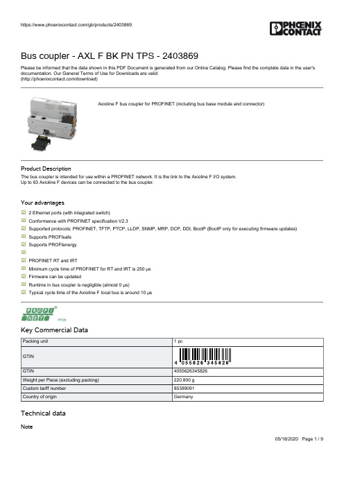
Phoenix Contact Axioline F 总线耦合器-PROFINET数据手册说明书
05/18/2020 Page 1 / 9Bus coupler - AXL F BK PN TPS - 2403869Please be informed that the data shown in this PDF Document is generated from our Online Catalog. Please find the complete data in the user's documentation. Our General Terms of Use for Downloads are valid (/download)Axioline F bus coupler for PROFINET (including bus base module and connector)Product DescriptionThe bus coupler is intended for use within a PROFINET network. It is the link to the Axioline F I/O system. Up to 63 Axioline F devices can be connected to the bus coupler.Your advantages2 Ethernet ports (with integrated switch) Conformance with PROFINET specification V2.3Supported protocols: PROFINET, TFTP, PTCP, LLDP, SNMP, MRP, DCP, DDI, BootP (BootP only for executing firmware updates) Supports PROFIsafe Supports PROFIenergyPROFINET RT and IRTMinimum cycle time of PROFINET for RT and IRT is 250 μs Firmware can be updatedRuntime in bus coupler is negligible (almost 0 µs)Typical cycle time of the Axioline F local bus is around 10 μsKey Commercial DataTechnical dataNoteBus coupler - AXL F BK PN TPS - 2403869Technical dataNoteDimensionsAmbient conditionsConnection dataGeneralInterfaces05/18/2020 Page 2 / 9Bus coupler - AXL F BK PN TPS - 2403869Technical dataInterfacesSystem limits of the bus couplerAxioline potentialsStandards and RegulationsEnvironmental Product ComplianceDrawings05/18/2020 Page 3 / 9Bus coupler - AXL F BK PN TPS - 2403869Connection diagram05/18/2020 Page 4 / 9Bus coupler - AXL F BK PN TPS - 2403869Dimensional drawingClassificationseCl@ssETIM05/18/2020 Page 5 / 905/18/2020 Page 6 / 9Bus coupler - AXL F BK PN TPS - 2403869ApprovalsApprovalsApprovalsPROFINET / null / null / nullEx ApprovalsApproval detailsPROFINETZ11944AccessoriesAccessoriesData cable by the meterNetwork cable - FL CAT5 HEAVY - 2744814CAT5-SF/UTP cable (J-02YS(ST)C HP 2 x 2 x 24 AWG), heavy-duty installation cable, 2 x 2 x 0.22 mm², solid conductor, shielded, outer sheath: 7.8 mm diameter, inner sheath: 5.75 mm ± 0.15 mm diameterNetwork cable - FL CAT5 FLEX - 2744830CAT5-SF/UTP cable (J-LI02YS(ST)C H 2 x 2 x 26 AWG), light-duty, flexible installation cable 2 x 2 x 0.14 mm²,stranded, shielded, outer sheath: 5.75 mm ± 0.15 mm diameterDevice marking05/18/2020 Page 7 / 9Bus coupler - AXL F BK PN TPS - 2403869AccessoriesInsert label - EMT (35X18,7)R - 0801831Insert label, Roll, white, unlabeled, can be labeled with: THERMOMARK ROLLMASTER 300/600, THERMOMARK X1.2, THERMOMARK ROLL X1, THERMOMARK ROLL 2.0, THERMOMARK ROLL, mounting type: snapped into marker carrier, lettering field size: 35 x 18.7 mm, Number of individual labels: 500DIN rail connectorBus connector - AXL BS BK - 2701422Axioline F bus base module for housing type BKPlugRJ45 connector - FL PLUG RJ45 GR/2 - 2744856RJ45 connector, shielded, with bend protection sleeve, 2 pieces, gray for straight cables, for assembly on site. For connections that are not crossed, it is recommended that you use the connector set with gray bend protection sleeve.RJ45 connector - FL PLUG RJ45 GN/2 - 2744571RJ45 connector, shielded, with bend protection sleeve, 2 pieces, green for crossed cables, for assembly on site. For connections that are crossed, it is recommended that the connector set with green bend protection sleeves is used.Programming cableConnecting cable - CAB-USB C/ USB C/1,8M - 1021809Connecting cable, for connecting the controller to a PC from USB C to USB C05/18/2020 Page 8 / 9Bus coupler - AXL F BK PN TPS - 2403869AccessoriesConnecting cable - CAB-USB A/ USB C/1,8M - 2404677Connecting cable, for connecting the controller to a PC from USB A to USB CSoftware libraryFunction block - SAFE AI - 2400057Function block library for safety-related analog value acquisition with standard I/O modules. Please contact the safety hotline (+49 5281 9-462777) before ordering the SAFE AI article.Terminal markingZack marker strip - ZB 20,3 AXL UNPRINTED - 0829579Zack marker strip for Axioline F (device labeling), in 2 x 20.3 mm pitch, unprinted, 25-section, for individual labeling with B-STIFT 0.8, X-PEN, or CMS-P1-PLOTTERZack Marker strip, flat - ZBF 10/5,8 AXL UNPRINTED - 0829580Zack Marker strip, flat, Strip, white, unlabeled, can be labeled with: PLOTMARK, CMS-P1-PLOTTER, mounting type:snap into flat marker groove, for terminal block width: 10.15 mm, lettering field size: 4 of 10.15 x 5 mm and 1 of 5.8 x 5 mm, Number of individual labels: 50Assembly tool - FL CRIMPTOOL - 2744869Crimping pliers, for assembling the RJ45 plugs FL PLUG RJ45..., for assembly on sitePhoenix Contact 2020 © - all rights reserved05/18/2020 Page 9 / 9。
RL0607无屏蔽耦合器纤维芯导线电容器产品说明说明书

Product features•Unshielded, leaded drum core•Protective sleeving over winding•Inductance range from 6.8 μH to 1500 μH•Current range from 0.12 A to 2.23 A •5.7 mm OD x 7.3 mm through-holepackage•Ferrite core materialApplications• LED Drivers and lighting • Utility meters• Appliances and white goods • Motor drives • Power supplies•General purpose filteringEnvironmental data•Storage temperature range (Component):-40 °C to +125 °C•Operating temperature range: -40 °C to +125 °C(ambient plus self-temperature rise)RL0607Unshielded radial leaded drum core inductors7HALOGENHF FREEPb D i s c o n t i n u e d e f f e c t i v e J u n e 15, 2018o r u n t i l i n v e n t o r y i s d e p l e t e d . No r e c o m me n d e d r e p l a c e m e n t a v a i l a b le .2Technical Data 10334Effective October 2017RL0607Unshielded radial leaded drum core inductorsDimensions - mmProduct specificationsPart Number 4OCL¹ (μH) ±10%I rms 2 (A )I sat 3 (A )DCR (Ω) @ +20 °C max.SRF (MHz) typ.RL0607-6R8-R 6.8 ± 20%2.23 1.820.03826RL0607-100-R 10 1.82 1.510.05821RL0607-180-R 18 1.52 1.130.08316RL0607-330-R 33 1.080.8400.17111RL0607-470-R 470.9530.6900.2178RL0607-820-R 820.6860.5300.4266RL0607-151-R 1500.5200.3900.7304RL0607-221-R 2200.4230.320 1.103RL0607-471-R 4700.3060.220 2.002RL0607-821-R 8200.2190.170 4.132RL0607-102-R 10000.2050.150 4.761RL0607-152-R15000.1660.1207.2011.Open Circuit Inductance (OCL) Test Parameters: 10 kHz, 0.1 V rms , 0.0Adc,+25 °C2.I rms : DC current for an approximate temperature rise of 40 °C without core loss. Derating is necessary for AC currents. PCB layout, trace thickness and width, air-flow, and proximity of other heat generating components will affect the temperature rise. It is recommended that the temperature of the part not exceed +125 °C under worst case operating conditions verified in the end application.3. I sat : Peak current for approximately 5% rolloff at +25 °C4.Part Number Definition: RL0607-yyy-R-RL0607 = Product code and size-yyy= Inductance value in μH, R = decimal point,if no R is present then third character = number of zeros.-“-R” suffix = RoHS compliantSide view Recommended pad layout SchematicTop viewPart marking: 1xxxwly R1 = RL0607xxx = inductance in µH, R = decimal point; if there is no R, then third character = number of zeros wly = date code, R = revision level*Lead length is after the components are trimmed from the packaging tape roll.Do not route traces or vias underneath the inductor/el ectronicsf f e c t i v e J u n e 15, 2018o r d e p l e t e d . No r e c c e m e n t a v a i l a b l e ./el ectronics3RL0607Unshielded radial leaded drum core inductorsTechnical Data 10334Effective October 2017Packaging information - mmInductance characteristics020406080100120020406080100120140160180200% o f O C L% of I sat% of OCL vs % of I satD i s c o n t i n u e d e f f e c t i v o r u n t i l i n v e n t o r y i s d e p l e N o r e c o m me n d e d r e p l a c e m e le .Technical Data 10334Effective October 2017RL0607Unshielded radial leaded drum core inductorsReference EN 61760-1:2006 Profile Feature Standard SnPb Solder Lead (Pb) Free SolderPreheatTemperature min. (T smin ) 100°C100°C Temperature typ. (T styp ) 120°C 120°C Temperature max. (T smax ) 130°C130°CTime (T smin to T smax ) (t s )70 seconds 70 seconds∆preheat to max Temeperature150°C max. 150°C max. Peak temperature (T p )235°C - 260°C250°C - 260°CTime at peak temperature (t p )10 seconds max5 seconds max each wave 10 seconds max5 seconds max each wave Ramp-down rate~ 2 K/s min ~3.5 K/s typ ~5 K/s max ~ 2 K/s min ~3.5 K/s typ ~5 K/s max Time 25°C to 25°C4 minutes4 minutesManual solder350°C, 4-5 seconds. (by soldering iron), generally manual, hand soldering is not recommended.T e m p e r a t u r eTimeT T T T ∆Wave solder profileLife Support Policy: Eaton does not authorize the use of any of its products for use in life support devices or systems without the express written approval of an officer of the Company. Life support systems are devices which support or sustain life, and whose failure to perform, when properly used in accordance with instructions for use provided in the labeling, can be reasonably expected to result in significant injury to the user.Eaton reserves the right, without notice, to change design or construction of any products and to discontinue or limit distribution of any products. Eaton also reserves the right to change or update, without notice, any technical information contained in this bulletin.EatonElectronics Division 1000 Eaton Boulevard Cleveland, OH 44122United States/el ectronics © 2017 EatonAll Rights Reserved Printed in USAPublication No. 10334 BU-SB14688October 2017Eaton is a registered trademark.All other trademarks are property of their respective owners.D i s c o n t i n u e d e f f e c t i v e J u n e 158o r u n t i l i n v e n t o r y i s d e p l e t e d . No r e c o m me n d e d r e p l a c e m e n t a v a i l a b le .。
pTYLCU-SS8使用说明书
TYLCU-SS8机车逻辑控制装置使用说明书深圳市通业科技发展有限公司二零零三年二月前言 (1)一、概述 (2)二、装置构成 (2)三、主要技术参数 (3)四、工作原理 (4)五、安装与使用 (6)六、TYLCU工作状态说明 (8)附图1、逻辑关系梯形图 (144)附表2:TYLCU对外插座连接定义 (25)本产品在出厂前已经过严格检查。
TYLCU装置购入后,请检查本产品是否因运输不慎而造成损伤;产品的规格、型号是否与订购产品的机种相符;有无合格标志等。
如有问题,请与本公司或供应商联系。
本产品的保修期依照标书约定。
若由于下述原因引起的故障,不属于保修范围:●不正确的操作或未经允许自行修理及改造所引起的问题。
●超出标准规范或未经允许自行修理及改造所引起的问题。
●购买后跌损、野蛮搬运、未按本说明书要求使用造成的问题。
●因环境不良所引起的器件老化或故障。
●为确保设备的良好运行,禁止非专业人员随意打开机箱。
专业人员进行维修时要注意确保人身安全。
一、概述TYLCU-SS(TongY e Logical Control Unit for ShaoShan)系列机车逻辑控制装置是专为国产韶山系列电力机车设计开发的、用于电力机车整车逻辑控制的新一代智能型逻辑控制装置。
旨在取代原有机车直流110V有触点控制电路,取代机车上原有的时间继电器,中间继电器等低压电器及大量的迂回电路,并预留与机车微机网络的通讯。
TYLCU-SS机车逻辑控制装置结合了世界先进的现代电子和计算机技术,采用了内嵌单片机系统的大规模可编程逻辑阵列结构及CAN总线技术,整个组合逻辑固化软件来实现基本控制功能,提高系统运行的可靠性。
TYLCU-SS系列机车逻辑控制装置的设计符合TB/T1394-93《铁路机车动车电子装置》的要求,结合了通用PLC的特点和电力机车的具体运行环境。
机车逻辑控制装置的使用将改变原有机车控制部分设计变更困难、调试烦琐、布线混乱、可靠性低的现象,实现电力机车逻辑控制的集成化和智能化。
光纤配线架及耦合器的安装和注意事项_概述说明
光纤配线架及耦合器的安装和注意事项概述说明1. 引言1.1 概述光纤配线架及耦合器是光通信系统中必不可少的设备,用于实现光纤线缆的布置、连接和分配,以及保证信号传输的质量和稳定性。
本文将详细介绍光纤配线架和耦合器的安装方法以及需要注意的事项,帮助读者正确使用这些设备并避免常见的问题。
1.2 文章结构本文分为五个主要部分,每个部分内容相对独立但又紧密相关。
首先是引言部分,简要概述了文章的背景和目的,并给出了整篇文章的结构框架。
接下来是第二部分,详细介绍了光纤配线架的安装步骤和注意事项。
第三部分则专注于光纤耦合器,包括其种类、功能以及安装过程中需要注意的事项。
第四部分探讨了其他相关设备的安装方法和注意事项,如光源、光功率计以及OTDR等设备。
最后一部分为总结与结论。
1.3 目的本文旨在提供关于光纤配线架及耦合器安装和注意事项方面全面而实用的指导,帮助读者了解这些设备的基本原理和使用方法,提高其在光通信系统中的安装和维护能力。
通过本文的阅读,读者将能够正确搭建光纤配线架,选择合适的光缆布置和连接方式,并了解如何确保耦合质量及维护其他相关设备。
最终目标是提升整个光通信系统的性能和可靠性。
2. 光纤配线架的安装和注意事项2.1 搭建光纤配线架的基本步骤在安装光纤配线架之前,我们需要进行以下基本步骤:1. 确定光纤配线架的位置:选择合适的位置来放置光纤配线架,确保其能够满足日后的扩展需求,并且便于维护和管理。
2. 安装固定件:根据场景需求,选择适当的固定件将光纤配线架固定在墙壁或机房中。
3. 组装框体结构:根据光纤配线架类型和规格,按照说明书将支架、框体及其他组件组装好。
4. 安装端子盒:将端子盒与光缆连接起来,并安装在相应位置上。
确保连接端良好并紧固稳定。
5. 进行标识和整理:为了方便管理与维护,在完成安装后使用标签或贴纸对不同端口及相关设备进行编号和标识。
同时,整理好连接线缆,避免交叉和混乱。
2.2 光缆布置及连接方式正确布置和连接光缆可以确保信号传输质量和网络稳定性。
液力耦合器的使用与维护
6 8・
科 技 论 坛
液力耦 合器 的使用 与维护
张振 , 河南 郑州 4 5 0 0 0 0 ) 摘 要: 从应用角度 出发 , 针对重点部件 、 常见故 障等 问题 , 阐述液力耦合 器的拆卸、 安装使用要 求与维护注意事项。
关键词 : 液 力耦 合 器 ; 使 用; 维护
液力耦合器是以液体 为工作介质 的一种非刚性联轴器 , 又称液 压 , 引起渗漏 , 甚 至造成机 械损坏 ; 注液 量小于 工作腔容 积的 4 0 % 力联轴器 。具有 良好的传 动性 能和保护性能 , 在输送机 电动 机和减 时 , 会 降低传递功率和效率 , 并使轴 承得 不到充分 润滑 , 产生噪声而 速器之间使用液力耦合 器 ,可实现 电动机 空载启 动和负载平缓启 过早损坏 。 动, 吸收 冲击和消除扭转振动 , 在多机驱动 中能使负载均衡 , 保护电 3 易熔塞 的要求 动机和整个传 动系统 。 因此 , 在煤矿机械中广泛应用 。 但 如果使用不 易熔塞是液力耦合器 的过载保护装置 , 只要液力耦合器 中的油 当, 液力耦合器将无 法正常工作 , 引发故障 , 甚 至设备停运 , 影响生 液温 度达 到 易熔 塞 中的低 熔 点合 金 ( 铅、 铋、 锑合金) 的熔 点 ( 约 产效率 。 在此 , 从实用角度出发 , 阐述液力耦合器 的使用与维护注意 1 1 0 — 1 4 0 %) , 塞孔 中的合金即被熔化甩 出 , 工作 油液在旋转离 心力 事项 。 的作用下 , 从易熔塞孔 中喷 出。 液力耦 合器不再传递扭矩 , 从而起到 1使用注意事项 保护作用。 易熔塞 中的低熔点合 金熔化 , 造 成液力耦合器喷液后 , 应 1 . 1注意传动方 向是否正确 。从理论上讲 平面叶片工作轮液力 立 即停机检查并排 除故障 , 并 向液力耦合器按定量注入新油 。同时 耦合器可做正反两个 方向的运转 , 但在安装好后 , 第一次通 电试 车 必须换上新的同型号易熔塞 , 决不允许 以木塞 、 螺栓等代替 , 或在 易 时, 必须检查液力耦合器 是否符合工作机要求 的旋转 方向 ; 在运转 熔合金孔 中填人保 险丝 ( 熔点约 3 0 0 %) , 否则就会失去过载保 护作 时应平稳 , 无异常噪声。 用, 造成严重后果 。 1 . 2为保证生 产安全 , 在液力耦合 器上应安 装防护罩 , 在工作 4 液力耦合器 的拆装注意事项 过程 中禁止打开防护罩 。 4 . 1液力耦合器拆卸 。拆卸工具应 为专 用工具 , 未 经专业维修 1 _ 3当电动机启动后达到额定转速时 ,从动机应开始运 转 , 否 人员 同意 , 不得 随意拆卸液力耦 合器主体 , 以免破坏密封 与平衡精 则应 立即停车 , 检查负载是否太重 或有卡阻现象 , 排除故障后再 重 度等 问题的发生。 拆卸前 , 应将其表面煤粉等赃物清洗干净 , 同时要 新启 动。 保证泵轮 、 外壳和辅助室外壳 的位置不要错动 , 要更 换的螺栓 、 螺母 1 . 4运转或停车时 , 液力耦 合器 中工作液体均不允许有 任何 渗 规格一致 。 拆卸时 , 先将电动机底板紧 固螺栓松开 , 再移动电动机 并 漏现象。 使联 轴节左右分离 , 用液力器卸下 电动机轴 上的半联轴器 , 最后 用 1 . 5连续运转 时 , 液力耦合器 中的工作液体温 度不得超过使用 拆卸螺杆旋人液力耦合 器主轴 的拆卸螺纹孔 , 将液力耦 合器主体顶 说明书规定值 。 出拆下。在整个过程中禁止 敲击液力耦合器铝制外壳 。 1 . 6 液力 耦合 器运转 3 0 0 0 h 后, 应对 其中工作液体品质进行检 4 . 2液力耦合器的的安装 。液力耦合器安装 时应在工作机与动 查, 如发现油质变坏 , 应更新油液 。 力机的轴上涂上润滑油脂 , 安装过程 中不允许用压板或铁锤敲打液 1 . 7定期 检查 弹性联轴器弹性块磨损情况 , 必要 时予 以更换 。 力耦合器铝制壳体 , 也不 可热装 , 以免损坏密封元件。 可在工作机 的 1 . 8定期检查 电动机轴与工作机输入轴 的安装精 度 , 并进行校 轴上绞螺纹孔 , 并在其上旋人螺杆 。通过旋转螺杆上 的螺母将套在 正。 螺杆上 的液力耦合 器主轴 ( 连带液力耦合器 ) 平衡带入 , 并将其安装 1 . 9不允许随意拆 开液力耦合器 , 以免损坏密封和其他构件 。 在工作设备上。原动机及工作机轴的同轴度允许误差为 ≤0 . 2 5 mm, 1 . 1 0经常检查 易熔合金 保护塞 ,切 不可用其 他物 品替 代 , 同 角度误差 ≤3 O ’ 。将直线传动式液力耦合 器安装在原动机及工作轴 时, 应将液力耦合器外壳圆周上所有螺栓重新检查 紧固一次 。 上后一定要精心找正 ,以免安装不 同心引起振动及 断轴事故发生 。 2正确使用工作液体 找正时 , 以工作机为安装基准 , 电动机和液力耦 合器的 吊装 、 定位 、 2 . 1工作 液体 的选择 。工作液体是液力耦合器能量转换和传递 粗调后 的基础在操作试 车前应精调基准 。精调 时以技术要求 为准 力矩 的工作介质 。工作液体 的种类 、 品质和充液量对 液力耦合器 的 绳 , 以工作机为基准找正液力耦合器 , 再以液力耦合 器找正电动机。 工作 和安全性能影响很大。 工作液体 的性能直接影 响到液力耦合器 另外 , 液力耦合器 的安装轴 线应低于 电动机和工作 机的轴线 , 为液 传 递力矩 、 功率的能力 、 效率和使用 寿命 , 所 以工作液体品质的优劣 力耦合器热状态工作室预 留一定的膨胀量 , 以保证液力耦合器热态 至关重要 。在液力传递 中, 希望工作液体具有低粘度 、 大重度 、 高闪 工作时能够有较高的同轴度 。 点、 低凝点 、 耐老化 、 少腐蚀 、 不渗漏 等性能 。 然而上述性能条件有些 5 常见故 障及处理 是相互制约 的 , 只能予 以综 合考虑 , 选 择不 同工作要求 的液力耦合 5 . 1工作机械达不到额定转速。造成这种现象有可能是 由下列 器最适合的工作 液体 。选择工作液体时 , 应 注意不要将不 同种类 的 原因导致 的 : 驱动电动机有毛病或链接不正确 ; 工作机械被卡住 ; 液 工作液体混在一起使 用。否则会对液力耦合器产生不利影响。 力耦合器漏液或注液量太少 ; 工作机构超负荷运输 ; 轴、 键安装不正 2 . 2工作液体 的注液量 。每种型号的液力耦合器都有一定的传 确或发生滚键现象 。 递 力矩( 功率 ) 范围, 称 为功 率带 , 它 与液力耦 合器的注液量范 围相 5 . 2易熔 合金保 护塞频 繁熔化 。出现这种现象 的原 因有 : 液力 对应 。合适 的注液量应使电动机的过载 能力得到充分利用 , 即液力 耦合器 主页量太少或漏液 ;电动机绕组星形连接状 态运转时 间太 耦 合器 的启动力矩应为 : 长; 工作机械过 载或被卡住 , 制动时间过长 , 消耗功率太大 ; 启动过 M q = ( O . 9 — 0 . 9 5 ) Mm a x 于频繁 ; 易熔合金熔点偏低等。要针对不 同原因逐一排 除。 式中 , Mm a x 为 电动机的最大力矩 ; 并 且液力耦合器在额定工况 5 . 3设备运转不平稳 。产生原 因有 : 电动机轴与工作机械轴 安 时效率 最高 , 即 , r I = i - - O . 9 6 — 0 . 9 8时 , 其 输入特性 曲线与 电动 机的机 装偏差超 限; 轴承损坏或液力耦合器注油量偏少 ; 底座松动 ; 弹性连 械特性 曲线相交于额定工作点 。 接块损 坏等 。应查准部位 , 予以处理。 液力耦合器注液量范围为其工作腔容积的 4 0 % 8 0 %,一般不 6结论 允许超 出此范 围, 更不允许将工作液体充满工作 腔。注液量超过工 只有熟 练掌握液力耦合器 的结构原理 、 安装 、 使用要求 , 才能减 作腔容积 的 8 0 %时 , 会使液力耦合器在运转时因过 载而急剧 升温 升 少事故的发生 , 保证设备安全高效运行 , 为企业创造经济效益 。
高压光电耦合器EL852系列说明书

4 PIN DIP HIGH VOLTAGE PHOTODARLINGTON PHOTOCOUPLER EL852 SeriesFeatures:•High collector- emitter voltage (VCEO=350V) • Current transfer ratio(CTR: 1000% min. at I F =1mA, V CE =2V) • High isolation voltage between input and output (Viso=5000 V rms ) • Creepage distance >7.62 mm• Operating temperature up to +100°C • Compact small outline package • Pb free and RoHS compliant. • UL approved • VDE approved• SEMKO approved • NEMKO approved • DEMKO approved • FIMKO approvedDescriptionThe EL852 series consists an infrared emitting diodes, optically coupled to a high voltage photo Darlington detector.It is packaged in a 4-pin DIP package and available in wide-lead spacing and SMD option.Applications• Telephone set, telephone exchangers • Sequence controllers• System appliances, measuring instruments• Signal transmission between circuits of different potentials and impedancesSchematicPin Configuration 1. Anode 2. Cathode 3. Emitter 4. CollectorAbsolute Maximum Ratings (Ta=25℃)Parameter Symbol Rating Unit Input Forward current I F60 mA Peak forward current (1us, pulse) I FP 1 AReverse voltage V R 6 VPower dissipationNo derating required up to Ta = 100°CP D100 mWOutput Power dissipationDerating factor (above Ta = 80°C) P C300 mW5.8 mW/°CCollector current I C150 mACollector-Emitter voltage V CEO350 VEmitter-Collector voltage V ECO0.1 V Total power dissipation P TOT320 mWIsolation voltage *1V ISO5000 V rmsOperating temperature T OPR-55 ~ +100 °CStorage temperature T STG-55 ~ +125 °CSoldering Temperature*2T SOL260 °C Notes:*1 AC for 1 minute, R.H.= 40 ~ 60% R.H. In this test, pins 1 & 2 are shorted together, and pins 3 & 4 are shorted together. *2 For 10 secondsElectro-Optical Characteristics (Ta=25℃unless specified otherwise)InputParameter Symbol Min. Typ.* Max. Unit ConditionForward Voltage V F- 1.2 1.4 V I F= 10mAReverse Current I R- - 10 µA V R = 4VInput capacitance C in- 30 250 pF V = 0, f = 1kHz OutputParameter Symbol Min. Typ.* Max. Unit ConditionCollector-Emitter darkcurrentI CEO- - 200 nA V CE= 200V, I F = 0mA Collector-Emitterbreakdown voltageBV CEO350 - - V I C = 0.1mAEmitter-Collectorbreakdown voltageBV ECO0.1 - - V I E = 0.1mATransfer CharacteristicsParameter Symbol Min. Typ.* Max. Unit Condition Current Transfer ratio CTR 1000 - 15000 % I F= 1mA ,V CE= 2V Collector-Emittersaturation voltageV CE(sat)- - 1.2 V I F = 20mA ,I C = 100mAIsolation resistance R IO5×1010- - ΩV IO = 500Vdc, 40~60% R.H.Floating capacitance C IO- 0.6 1.0 pF V IO = 0, f = 1MHzCut-off frequency fc - 7 - kHz V CE = 2V, I C = 20mA R L = 100Ω, -3dBRise time t r- - 300 µsV CE = 2V, I C = 20mA,R L = 100ΩFall time t f- - 100 µs* Typical values at T a = 25°CTypical Electro-Optical Characteristics CurvesOrder InformatioPart NumberEL852X(Y)-VNoteX = Lead form option (S, S1, M or none)Y = Tape and reel option (TA, TB ,TU, TD or none).V = VDE safety (optional).Option Description Packing quantity None Standard DIP-4 100 units per tube M Wide lead bend (0.4 inch spacing) 100 units per tube S (TA) Surface mount lead form + TA tape & reel option 1000 units per reel S (TB) Surface mount lead form + TB tape & reel option 1000 units per reel S1 (TA) Surface mount lead form (low profile) + TA tape & reel option 1000 units per reel S1 (TB) Surface mount lead form (low profile) + TB tape & reel option 1000 units per reel S (TU) Surface mount lead form + TU tape & reel option 1500 units per reel S (TD) Surface mount lead form + TD tape & reel option 1500 units per reel S1 (TU) Surface mount lead form (low profile) + TU tape & reel option 1500 units per reel S1 (TD) Surface mount lead form (low profile) + TD tape & reel option 1500 units per reelPackage Dimension (Dimensions in mm) Standard DIP TypeOption M TypeOption S TypeOption S1 TypeRecommended pad layout for surface mount leadformDevice MarkingEL852YWWVNotesEL denotes EVERLIGHT852 denotes Device NumberY denotes 1 digit Year codeWW denotes 2 digit Week codeV denotes VDE optional11DPC-0000056 Rev. 6Tape & Reel Packing SpecificationsTape dimensionsDimension No. Ao Bo Do D1 E F Dimension (mm)S.S1 4.90±0.1 10.40±0.11.5±0.1 1.50±0.11.75±0.1 7.50±0.1 Dimension No. Po P1 P2 t W Ko Dimension (mm)S.S14.00±0.18.00±0.2.00±0.10.40±0.116.00±0.34.60±0.112Copyright © 2010, Everlight All Rights Reserved. Release Date : May 27, 2014. Issue No: DPC-0000056 Rev. 6Precautions for Use1. Soldering Condition1.1 (A) Maximum Body Case Temperature Profile for evaluation of Reflow ProfileNote: Reference: IPC/JEDEC J-STD-020DPreheatTemperature min (T smin ) 150 °C Temperature max (T smax )200°CTime (T smin to T smax ) (t s )60-120 seconds Average ramp-up rate (T smax to T p )3 °C/second maxOtherLiquidus Temperature (T L )217 °C Time above Liquidus Temperature (t L ) 60-100 sec Peak Temperature (T P )260°C Time within 5 °C of Actual Peak Temperature: T P - 5°C 30 sRamp- Down Rate from Peak Temperature 6°C /second max. Time 25°C to peak temperature 8 minutes max. Reflow times 3 times.DISCLAIMER1. Above specification may be changed without notice. EVERLIGHT will reserve authority on material change for abovespecification.2. When using this product, please observe the absolute maximum ratings and the instructions for using outlined in thesespecification sheets. EVERLIGHT assumes no responsibility for any damage resulting from use of the product which does not comply with the absolute maximum ratings and the instructions included in these specification sheets.3. These specification sheets include materials protected under copyright of EVERLIGHT corporation. Please don’treproduce or cause anyone to reproduce them without EVERLIGHT’s consent.13Rev. 。
贴片光电耦合器简介及应用

光电耦合器(以下简称光耦)是一种发光器件和光敬器件组成的光电器件。
它能实现电一光一电信号的变换,并且输入信号与输出信号是隔离的。
U前极大多数的光耦输入部分采用神化镣红外发光二极管,输出部分釆用硅光电二极管、硅光电三极管及光触发可控硅。
这是因为峰值波长900~940nm的神化稼红外发光二极簣能与硅光电器件的响应峰值波长相吻合,可获得较高的信号传输效率.光耦的结构光耦的内部结构(剖面)如图1所示。
光耦输入部分大都是红外发光二输岀部分有不同的光敬器件,如图2所示。
光敏器件管心塑料封装外喘发光簷管心透明硅胶电极引脚这里要说明的是,图2 (c)的输入部分有两个背对背的红外发光二管,它用于交流输入的场合;图2 (d)采用达林顿输出结构,它可使输出获得较大的电流;图2 (e)、2(f)的输出山光触发双向可控硅组成,它们主要用来驱动交流负载。
图2(e)与图2 (f)的差别是图2(f)有过零触发控制(图中的“ZC”即“过零”的意思),而图2(e)没有过零触发控制电路。
基本电路光耦的基本电路如图3所示•图3 (a)的负载电阻RL接在发射极及地之间,图3 (b)的负载电阻RL接在电源Vdd与集电极之间.在图3 (R中,输入端加上Vcc电压,经限流电阻Rin后,有一定的电流IF 流经红外发光二极管,IF与Vcc、发光二极管的正向压降VF及Rin的关系为:I F二(Vcc-VF)/Rin。
式中的VF取1。
3V« IF的最大值由资料给出(一般工作时IF WlOmA)・发光二极管发光后,光电三极管导通,集电极电流Ic III Vdd经光电三极管流过RL到地,使输出电压Vout=IcXRL(或Vout二Vdd—VCE, VCE为光电三极管的管压降)。
图3(b)的工作原理与图3 (a)相同,不再重复。
图3中输入、输出也可用各自的地。
从图3 (a)可以看出;输入端不加Vcc电压,输岀端Vout=0V,输入端加了V CC 电压,负载得电,这个功能相当于“继电器”。
信息产业部电子第四十四所 重庆光电技术研究所 光电耦合器 说明书

输出漏电流
IOff
输出低电平
VOL
选通端高电平电流 IEH
选通端低电平电流 IEL
1.3 1.7 V IF=10mA
1
A VR=5.0V,TA=25
100
A VCC=5.0V,IF=250 A,VE=2.0V
0.3 0.6 V VCC=5.0V,IF=10mA,IOL=4mA
-0.2 -0.4 mA VCC=5.0V,VE=2.0V
3 宽电源电压 4 .5V - 1 5 . 5 V 4 . 隔离电压 1 0 0 0 V 5 低功耗 2 0 m W ( V C C = 5 . 5 V )
主要用途 A / D D / A 电路 计算机接口电路 数字通讯电路 实时控制电路等.
3 宽电源电压 1 0 V - 1 8 V 4 . 隔离电压 1 0 0 0 V 5 低功耗 4 0 m W ( V C C = 1 5 . 5 V )
主要用途 A / D D / A 电路 计算机接口电路 数字通讯电路 实时控制电路等.
输出高电平 V O H 随温度 T 变化的关系
0.25 0.2
0.15 0.1
12
正向电压V F(V)
1.3
1.28
1.26
1.24
1.22
1.2
1.18
1.16
1.14
1.12
1.1
2
3
4
5
6
7
8
9
10
输 入 电 流 IF(mA)
正向电压 VF 随输入电流 IF 变化的关系
13
重光 COERI
上升时间 下降时间
隔离特性
符号 tPHL tPLH tr tf
永磁耦合器说明书

永磁耦合器无连接扭矩传递技术永磁耦合器是根据导磁体和永磁体之间的相互磁力耦合作用来传递扭矩的,是一种无机械连接的软启动设备,传递效率能达到95%以上,实现电机节能15%以上,提高功率因数0.2以上。
主要应用设备为泵、风机、离心负载、皮带运输机及其它机械装置,应用广泛。
永磁耦合器一、产品工作原理永磁耦合器是通过切割磁力线来传递转矩的,是一种创新型的传动链接产品。
永磁耦合器属于耦合传动的一种,可以实现非接触性的动力传递。
它是由两个独立的,没有任何接触的转体组成,这两个转体之间有一定的空隙。
其中导体转子(棕色)与电机输出端联接,永磁转子(紫色)与负载输入端联接。
电机转动过程中即导体转子与永磁转子产生相对运动,交变磁场通过气隙在导体转子铜盘上产生涡流,同时涡流产生感应磁场与永磁场相互作用,由于负载转矩作用,被动永磁转子仍处于静止,当主动导体转子转过一个角度后,其和永磁转子之间存在一定的转差角,从而使得静止的平衡状态被打破,主动端所转过的角度的大小取决于负载转矩的大小,此时从动端会受到电磁力矩的作用,电磁转矩随着主动端与从动端的转差角的增加而增大;当电磁转矩超过负载转矩时,从动端开始转动。
此后,在电动机的驱动下,主动端将与从动端保持一定的转差角度同步运行。
从而带动永磁转子沿着与铜转子相同的方向旋转,结果在负载侧输出轴上产生转矩,带动负载做旋转运动。
来实现动力的无接触传递。
实现电机与负载之间的扭矩传递。
永磁耦合器所能承受的最大负载转矩由静转矩特性的峰值转矩决定,当负载转矩值超过该峰值大小时,将会产生失步现象。
(附永磁耦合器原理图)。
原理图原理图上:棕色--代表导体转子紫色--代表永磁转子导体--为铜盘说明:此图用于对工作原理解释,并非实物结构图。
永磁耦合器效果图图1 图2 图3效果图上:灰色--代表导体转子橄榄色--代表永磁转子铁红色--代表铜盘※该永磁耦合器是由导体转子(铜导体)、永磁体转子组成,两者无连接。
300MW机组YOT51A型液力耦合器检修文件包
YOT51A型液力耦合器A检修文件包1范围本检修文件包适用于300MW机组YOT51A型液力耦合器A检修工作2本检修文件包涉及的文件、技术资料和图纸300MW机组YOT51A型液力耦合器设备技术标准300MW机组YOT51A型液力耦合器使用说明书300MW机组YOT51A型液力耦合器安装说明书及图纸3安全措施3.1严格执行《电业安全工作规程》。
3.2解体液力耦合器前必须确认动力源已切断、系统可靠隔绝,安全措施已经执行。
3.3拆开的管路、法兰等敞口部位要封闭好。
3.4行车起吊,必须有专业人员指挥、监护,起吊设备时起重臂下严禁站人,起吊重物前检查起重工器具是否符合载荷要求,起吊物件要绑扎牢固、起吊平稳。
3.5使用大锤时,严禁单手操作、严禁戴手套操作,使用前检查锤头的固定情况,防止飞出伤人。
3.6使用电动工器具必须配用漏电保护器。
3.7使用电动工器具必须戴绝缘手套。
3.8高空作业应使用工具带、安全带或防坠器。
3.9检修现场严禁吸烟,一经发现严格处理。
3.10检修时所有工作人员要认真负责,杜绝带情绪和饮酒后作业。
3.11拆卸轴瓦时要防止损坏轴瓦及碰伤轴径。
3.12液力耦合器回装时,认真检查内部无任何异物。
3.13每天开工前工作负责人向工作班成员交代安全注意事项,工作结束后,总结当天的安全工作情况。
4备品备件准备5现场准备及工器具W15.2工作准备□在检修作业现场地面铺好胶皮,做好作业区的物理隔离。
□通知热工检修人员,拆去有关仪表和温度测点。
□检查所有起吊装置和专用工具是否良好,并运至检修现场□开工前组织工作成员学习作业文件,对成员进行分工,并进行安全和技术交底,工作组成员应熟知工作内容及危险点的控制措施,掌握本作业指导书全部内容。
5.3确认工器具、备品配件、材料准备好,检验合格W25.4办理相关工作票□检修负责人与运行人员共同确认工作票安全措施已执行。
□检查验证工作票。
□动火工作票办理完毕。
6检修工序计划工日工艺流程1232110.5至下次检修6.1修前准备以及检修内容□通知热工检修人员,拆去有关仪表和温度测点。
液力耦合器与电机的装配步骤_概述说明

液力耦合器与电机的装配步骤概述说明1. 引言1.1 概述液力耦合器是一种常见的机械装置,它主要用于将传动能量从一个轴传输到另一个轴。
而电机则是一种将电能转化为机械能的设备。
液力耦合器与电机的装配步骤非常重要,对于确保机械设备的正常运行具有关键作用。
本文将详细介绍液力耦合器与电机的装配步骤及相关注意事项和常见问题解决办法。
通过了解液力耦合器组成部分、电机安装准备工作以及液力耦合器与电机的连接方法,读者可以全面理解如何正确安装液力耦合器和电机,并且能够应对可能遇到的问题。
1.2 文章结构本文共分为五个部分:引言、液力耦合器与电机的装配步骤、装配步骤详解、注意事项及常见问题解决办法以及结论。
在引言部分,我们首先介绍了液力耦合器与电机的背景和重要性,并说明了本文所要讨论的内容。
在第二部分中,我们将详细介绍液力耦合器组成部分的功能和特点,以及电机安装前的准备工作。
第三部分将详细讲解液力耦合器与电机的连接方法,并给出具体的装配步骤。
在第四部分,我们将列举一些注意事项,帮助读者避免常见的错误操作,并提供一些常见问题的解决办法。
最后,在结论中,我们将总结液力耦合器与电机的装配流程和重要步骤,并展望液力耦合器与电机应用的前景。
1.3 目的本文旨在向读者提供一个全面、清晰的指南,以帮助他们正确地进行液力耦合器与电机的装配。
通过阅读本文,读者将了解到每个步骤的详细操作流程,掌握相关技巧和注意事项,并能够解决可能出现的常见问题。
我们希望通过这篇文章,读者能够更加熟悉液力耦合器与电机装配过程,并为今后实际应用提供有益参考。
2. 液力耦合器与电机的装配步骤2.1 液力耦合器组成部分介绍液力耦合器是由泵轮、涡轮和导向叶片等组成的。
其中,泵轮由驱动电机带动,产生高速旋转;而涡轮则通过传递液体动能来驱动负载。
导向叶片位于泵轮和涡轮之间,用于引导流体在两者之间的转移。
2.2 电机安装准备工作在开始装配液力耦合器和电机之前,必须先进行一些准备工作。
液力耦合器
一、 概述
YOTFC500CL 调速型液力偶合器是安装在电机和工作机之间
的一种柔性液力传动元件,它使电机的功率通过液力偶合器泵轮
和涡轮之间的工作油的循环流动,平稳而无冲击地传递到工作
机,并可在电机输入转速恒定时,通过操纵勺管,对输出转速进
行无级调节。
偶合器在与恒速电机连接后,即输入转速不变时,用于离心
有△=αh△t α—— 材料线膨胀系数(10-6/℃)
故:
△1 = αyhy(ty-ts)-αDhD(tD-ts) △2 = αyhy(ty-ts)-αzhz(tz-ts)
偶合器 ty = 67℃ hy = 635 mm αy = 11×10-6/℃
注: 当△为正值时,说明偶合器找正中心高应低于找正基准
境温度 ts(℃)工作机中心高为 hz(mm),正常工作时使中心高
变化的温度 tz(℃),找正环境温度 ts(℃)。
△h ——— 三机允许工作温度范围的中心高变化量(mm)
△1 △2 —— 偶合器和电机,偶合器和工作机找正时的中
心高留量(mm)
tmax ———— 允许的最高工作温度(℃) tmix ———— 允许的最低工作温度(℃) 根据中心高热膨胀量计算公式:
八、偶合器的维修和保养
1.偶合器的拆卸(图 3) (1)脱开输入输出联轴器;
(2)拧下输入端盖和输出端盖螺钉; (3)打开偶合器箱盖; (4)脱开电动执行器拔杆与勺管调节连杆间的柱销将勺管抽出; (5)脱开轴承压盖上的接管,卸下轴承压盖,铂热电阻引线应小心
抽出; (6)将旋转组件吊出放在清洁的地面上或专用支架上。 (7)从两轴端由外向里依次拆下各件,直至推力盘及推力瓦。 (8)拆下外壳Ⅱ(件 12) (9)分开勺管壳体(件 13)取出勺管壳体内的两套径向瓦。
第五轮耦合器安装说明书

The fifth wheel coupling provides the link between a se-mi-trailer and the towing truck.The fifth wheel coupling is normally fixed to the tractor chas-sis by means of a mounting plate. Various mounting plates, fifth wheel mounting heights and fifth wheel leg heights are available to make an accurate match between the height of the fifth wheel and existing trailer systems possible.The following areas are described below:•Type•Mounting•Leg height•Maintenance level•Lubrication•Trailer connection indicatorFACT SHEETFifth wheel with installationSales variantsType5WT-FO14Fontaine 150SP25WT-FO15Fontaine 3000 series5WT-JO8Jost JSK 37C/E5WT-JO9Jost JSK 425WT-JO16Jost JSK 34H5WT-SH SAF-Holland/+GF+ SK-S 36.20Mounting5WM-ASL Mounting on an air-actuated slider and 4 mmL-profiles5WM-ASM Mounting on an air-actuated slider and 50mm L-profiles5WM-ISOL Mounting on a low saddle plate and L-profiles 5WM-ISOM Mounting on a medium saddle plate and L-profiles5WM-ISOH Mounting on a high saddle plate and Z-profiles 5WM-LPRO Mounting on L-profiles that are directlymounted on the frameLeg height5WH140Leg height 140 mm5WH150Leg height 150 mm5WH160Leg height 160 mm5WH175Leg height 175 mm5WH185Leg height 185 mm5WH190Leg height 190 mm5WH195Leg height 195 mm5WH200Leg height 200 mm5WH205Leg height 205 mm5WH210Leg height 210 mm5WH220Leg height 220 mm5WH230Leg height 230 mm5WH260Leg height 260 mmMaintenance level5WLM-B Basic maintenance5WLM-L Low maintenance with plastic top plate Lubrication5WL-S1Lubrication of the locking mechanism and top plate5WL-S2Lubrication of the locking mechanismTrailer connection indicatorTCIND Trailer connection indication with sensors forheight, king pin and coupling lockFACT SHEETFifth wheel with installationTypeThe following fifth wheel types are available:5WT-FO14Fontaine 150SP2 pressed steel fifth wheel. Mounted on outward facing L-profiles.Weight optimized. Available with a number of different heights above the framedepending on both fifth wheel mounting and fifth wheel leg height.5WT-FO15Fontaine 3000 series cast iron fifth wheel. Standard duty, 100% on motorway. Extra large king pin plate contact area (almost 360° contact area around king pin whenclosed) reduces wear, improves handling and provides added roll-over resistance.5WT-JO8Jost JSK 37C cast iron fifth wheel on fixed installations. Rubber mounting and shock absorbing rubber bearing. Suitable for poor quality roads.Jost JSK 37E on sliding and dual height installation. Rubber mounting.Both are available with a number of different heights above the frame depending onfifth wheel mounting and fifth wheel leg heights.FACT SHEETFifth wheel with installation5WT-JO9Jost JSK 42 weight-optimized cast iron fifth wheel. A plastic bearing protects the chassis due to its longitudinal elasticity (lateral movement). Suitable for the 5WM-LPRO mounting, providing a low weight solution. Available with a number of different heights above the frame depending on both fifth wheel mounting and fifth wheel legheight.5WT-JO16Jost JSK 34H weight optimized cast iron fifth wheel. Suitable for long haul operations with 5WM-LPRO mounting providing a low weight solution. Features a hybrid bearing,which is a combination of a robust shock absorbing rubber bearing (as in JSK 37C) anda plastic bearing.5WT-SHSAF-Holland/+GF+ SK-S 36.20 cast iron fifth wheel. Permanent maintenance-free bearing with rubber damper. Suitable for the 5WM-LPRO mounting, providing a low weight solution. Available with a number of different heights above the framedepending on both fifth wheel mounting and fifth wheel leg height.FACT SHEETFifth wheel with installationType specification● Standard, ○ Option, - Not available1For fifth wheel mountings 5WM-ISOL, 5WM-ISOM, 5WM-ASL and 5WM-ASM.2For fifth wheel mounting 5WM-LPRO.3Maximum imposed load.4Approximate value for low spec, without installation, comparable heights.FACT SHEETFifth wheel with installationMountingThe following fifth wheel mountings are available:5WM-ASLMounting plate bolted to two low L-profiles with outward facing flanges andadjustable, air-actuated slider. Two crossmembers and L-profiles bolted to frame.5WM-ASL has no saddle. The fifth wheel mounting has a self-locking mechanism and a pneumatically operated release mechanism (switch in instrument panel). Optimizedfor Volvo.5WM-ASMMounting plate bolted to two medium high L-profiles with outward facing flanges and adjustable, air-actuated slider. Two crossmembers and L-profiles bolted to frame.5WM-ASM has no saddle. The fifth wheel mounting has a self-locking mechanism and a pneumatically operated release mechanism (switch in instrument panel). Optimizedfor Volvo.5WM-ISOLMounting plate bolted to two low L-profiles with outward facing flanges. Suitable forall kinds of fifth wheels. Sliding members are not included in the variant.FACT SHEETFifth wheel with installation5WM-ISOMSaddle with two crossmembers and two tie plates are bolted to two medium high L-profiles with outward facing flanges. Suitable for all kinds of operations. Slidingmembers are not included in the variant.5WM-ISOHSaddle with two crossmembers and two tie plates are bolted to two on top of frame mounted high Z-profiles with outward facing upper flanges. Optimized for T-ride rearaxle installations. Sliding members are not included in the variant.5WM-LPROMounted directly to the chassis frame with two inverted L-profiles (facing inward).5WM-LPRO has no saddle and no mounting plate which allow for low couplingheights. Light fifth wheel alternative making it perfect for weight sensitive operations.FACT SHEETFifth wheel with installationMounting specification● Applicable, - Not applicable 1See fifth wheel specification table.2Maximum imposed load.3For 5WM-LPRO, the 8 mm L-profile is included in the total fifth wheel height.FACT SHEETFifth wheel with installationLeg heightFifth wheel height in mm from foot, upper edge of mounting,to the top of the fifth wheel in horizontal position (B). An ex-ception is the fifth wheel mounting 5WM-LPRO, that is mea-sured from the upper edge of the frame to the top of the fifthwheel in horizontal position (A).Simplified sketch of the measuring, where A is the measurement for 5WM-LPRO and B is the measurement for the other fifth wheel mountings.Leg height overview for fifth wheel type and fifth wheel mountingFACT SHEETFifth wheel with installationMaintenance level5WLM-B Basic fifth wheel maintenance level (for locking mechanism and top plate).5WLM-LLow fifth wheel maintenance level (for locking mechanism). Plastic slide plates and wear ring.Lubrication5WL-S1Locking mechanism and top plate lubrication(+2 kg).5WL-S2Locking mechanism lubrication (+1 kg).Trailer connection indicatorTCINDFifth wheel equipped with sensors for height,king pin and coupling lock. Trailer connection indication is shown in the instrument display (+1 kg).5WLM-B, 5WL-S1For applications with many couplings/uncouplings. Requires no manual greasing.Refillable system. Level of lubrication can be adjusted depending on need.5WLM-L, 5WL-S2For applications with few or very couplings/uncouplings. Automatic greasing of lock jaw. Battery driven, non-refillable. Canister to be replaced at same time as the lock jawis replaced.FACT SHEETFifth wheel with installation。
永磁耦合器说明书

永磁耦合器无连接扭矩传递技术永磁耦合器是根据导磁体和永磁体之间的相互磁力耦合作用来传递扭矩的,是一种无机械连接的软启动设备,传递效率能达到95%以上,实现电机节能15%以上,提高功率因数0.2以上。
主要应用设备为泵、风机、离心负载、皮带运输机及其它机械装置,应用广泛。
永磁耦合器一、产品工作原理永磁耦合器是通过切割磁力线来传递转矩的,是一种创新型的传动链接产品。
永磁耦合器属于耦合传动的一种,可以实现非接触性的动力传递。
它是由两个独立的,没有任何接触的转体组成,这两个转体之间有一定的空隙。
其中导体转子(棕色)与电机输出端联接,永磁转子(紫色)与负载输入端联接。
电机转动过程中即导体转子与永磁转子产生相对运动,交变磁场通过气隙在导体转子铜盘上产生涡流,同时涡流产生感应磁场与永磁场相互作用,由于负载转矩作用,被动永磁转子仍处于静止,当主动导体转子转过一个角度后,其和永磁转子之间存在一定的转差角,从而使得静止的平衡状态被打破,主动端所转过的角度的大小取决于负载转矩的大小,此时从动端会受到电磁力矩的作用,电磁转矩随着主动端与从动端的转差角的增加而增大;当电磁转矩超过负载转矩时,从动端开始转动。
此后,在电动机的驱动下,主动端将与从动端保持一定的转差角度同步运行。
从而带动永磁转子沿着与铜转子相同的方向旋转,结果在负载侧输出轴上产生转矩,带动负载做旋转运动。
来实现动力的无接触传递。
实现电机与负载之间的扭矩传递。
永磁耦合器所能承受的最大负载转矩由静转矩特性的峰值转矩决定,当负载转矩值超过该峰值大小时,将会产生失步现象。
(附永磁耦合器原理图)。
原理图原理图上:棕色--代表导体转子紫色--代表永磁转子导体--为铜盘说明:此图用于对工作原理解释,并非实物结构图。
盘式永磁耦合器效果图图1 图2 图3效果图上:灰色--代表导体转子橄榄色--代表永磁转子铁红色--代表铜盘※该永磁耦合器是由导体转子(铜导体)、永磁体转子组成,两者无连接。
vishay 型号 45 使用光耦合器归一化曲线说明书

V I S H AY S E M I C O N D U C T O R SOptocouplers and Solid-State RelaysHow to Use Optocoupler Normalized CurvesA P P L I C A T I O N N O T By Dimitrij Martins and Lars BayerINTRODUCTIONOptocouplers are used for signal transfer between a safe and a potentially hazardous or electrically noisy environment using galvanic isolation. The isolation voltage and noise rejection characteristics of the optocoupler are basically determined by the mechanical package design and isolating materials.A phototransistor optocoupler has an infrared emitting diode, which is optically coupled to a silicon phototransistor detector. The infrared light of the LED irradiates the photosensitive base collector junction of the phototransistor which is amplified by the collector current of the transistor.HOW TO USE THE NORMALIZED CURVESThe gain of the optocoupler is expressed as a currenttransfer ratio (CTR), which is the collector current (I C ) of the output divided by the forward current (I F ) of the input andmultiplied by 100 %. (1)There are typically a number of CTR groups (binning) to choose from when selecting an optocoupler. CTR is nota static value. t is affected by the forward current (F ),the collector-emitter voltage (V CE ), and the ambient temperature (T amb ). The datasheets include curves that show how each of these values can change based on ambient temperature. To be able to compare the performance of the optocoupler over temperature we normalize the curves. Normalization is the scaling of data to a nominal condition, typically at 25 °C and the coupler-specific forward current, as the graph in Fig. 1 shows (NCTR at T amb = 25 °C and I F = 5 mA is 1.0).Fig. 1 - Normalized Current Transfer Ratio (non-saturated) vs.Ambient TemperatureTwo separate CTRs are often needed to complete the interface design. One for the non-saturated or linear operation with a collector emitter voltage (V CE ) of 5.0 V and the second one for the saturated or switching operation witha collector emitter voltage (V CE ) of 0.4 V. The Fig. 1 illustratesthe normalized CTR curves vs. forward current for different ambient temperatures for the non-saturated operation and Fig. 2 for the saturated operation.CTR = I CI F---- x 100 %0.20.4 0.6 0.8 1.0 1.2N C T R - N o r m a l i z e d C T R (n o n -s a t u r a t e d )-60-40-2020406080100120T amb - Ambient Temperature (°C)How to Use Optocoupler Normalized CurvesA P P L I C A T I O N N O T Fig. 2 - Normalized Current Transfer Ratio (saturated) vs.Ambient TemperatureThe normalized form of the CTR graph in Fig. 3 and Fig. 4 provides a reference for a quick estimation on the variation of the CTR at different forward currents and ambient temperatures ranging from -55 °C to +100 °C.Fig. 3 - Normalized Current Transfer Ratio (non-saturated) vs.Forward CurrentFig. 4 - Normalized Current Transfer Ratio (saturated) vs.Forward CurrentThe following design example illustrates how the normalized curves can be used to calculate the appropriate load resistors.Example 1Using the VOL617A-3 optocoupler with a CTR range of 100 % to 200 % at a forward current of 5 mA in thenon-saturated mode with following conditions: T amb = 0 °Cto +70 °C, I F = 5 mA, V CC = 5 V, V CE = 0.4 VSOLUTIONStep 1Determine the saturated NCTR factor for the required temperature from 0 °C to +70 °C and a forward current of 5 mA by using Fig. 5.Fig. 5 - Normalized Current Transfer Ratio (saturated) vs.Ambient Temperature0.20.4 0.6 0.8 1.0 1.2 N C T R - N o r m a l i z e d C T R (s a t )-60-40-2020406080100120T amb - Ambient Temperature (°C)00.20.40.60.81.01.21.40.1110100N C T R -N o r m a l i z e d C T R (N S )I F -Forward Current (mA)0.20.40.60.81.01.20.1110100N C T R -N o r m a l i z e d C T R (s a t )I F -Forward Current (mA)N C T R - N o r m a l i z e d C T R (s a t .)T amb - Ambient Temperature (°C)0.75How to Use Optocoupler Normalized CurvesA P P L I C A T I O N N O T With the temperature range of 0 °C to +70 °C the CTR undergoes a change between 0 % and -25 % at a forward current of 5 mA.The CTR sat range over the required temperature will be about 100 x 0.75 = 75 % to 200 % x 0.75 = 150 % for a forward current of 5 mA. Step 2Select the load resistor using the following equation: (2)Example 2:Using an VOL617A-3 optocoupler in the circuit shown in Fig. 6, determine the worst-case load resistor under the following operation conditions:T amb = 75 °C, I F = 7 mA, V CC = 5 V, V CE = 0.4 V, logic load = microcontroller I/O VOL617A-3 characteristics:CTR non-sat. = 100 % at F = 5 mA, V CE = 5.0 V, and T amb = 25 °CFig. 6 - VOL617A-3 to Microcontroller InterfaceSOLUTIONStep 1Determine the saturated NCTR factor for the ambienttemperature of 75 °C and a forward current of 7 mA, which can be found in Fig. 7.Fig. 7 - Normalized Current Transfer Ration (saturated) vs.Forward CurrentThe saturated NCTR factor is 0.71.Assuming a ten year service life period of the interface circuit, allowance needs to be made for additional CTR reduction of approximately 20 % on account of degradation.Making an additional tolerance allowance of approximately -25 % for the CTR will result in a safe minimum value of approximately 42.6 %.(4) (5)Step 2Select the minimum load resistor using the followingequation:(6)R L V CC - V CEsat.I F x CTR sat.-------------------------------- 5 V - 0.4 V 5 mA x 0.75-------------------------------- 1.22 k ≥≥≥ΩV 00.20.40.60.711.01.20.1110100N C T R -N o r m al i z e d C T R (s a t )I F -Forward Current (mA)0.8CTR sat. = CTR min. x NCTR x aging x toleranceCTR sat. = 100 % x 0.71 x 0.8 x 0.75 = 42.6 %R Lmin.V CC - V CEsat.I F x CTR sat.-------------------------------- 5 V - 0.4 V 7 mA x 0.426----------------------------------- 1.54 k ≥≥≥Ω。
- 1、下载文档前请自行甄别文档内容的完整性,平台不提供额外的编辑、内容补充、找答案等附加服务。
- 2、"仅部分预览"的文档,不可在线预览部分如存在完整性等问题,可反馈申请退款(可完整预览的文档不适用该条件!)。
- 3、如文档侵犯您的权益,请联系客服反馈,我们会尽快为您处理(人工客服工作时间:9:00-18:30)。
耦合器使用说明书
隔离耦合器接在由不同电源供电的相邻两组支架控制器之间,将两组支架控制器实施电气隔离,为电源引入各组提供通道;内部有四个光电耦合器件,为两条数据通信线CANBUS和CANBidi信号双向传输提供通道。
隔离耦合器有4个插口,分别为A1、A2、A3和A4,两侧(每侧2个口)分别连接被隔离的两组控制器,靠外的插口接控制器,靠内的插口接12V电源,详见图1.1。
隔离耦合器工作电压DC12V,工作电流:A1侧不大于35mA;A4侧不大于25mA。
图1.1 SAC-I隔离耦合器
图1.2 SAC-I隔离耦合器接线口示意图
隔离耦合器接线:
A1——控制器邻架口
A2——电源
A3——电源
A4——控制器邻架口
接口4芯线说明:1接电源正极,4接电源负极;2、3线如果接电源则不连接,如果接控制器邻架口则接控制器的邻架CAN线。
