无线通信原理与应用第三章
《无线通信原理及应用》课后习题

《无线通信原理及应用》课后习题第1章无线传感器网络概述1、无线传感器网络的定义?2、传感器节点结构及其各部分功能?3、无线自主网的定义?4、传感网与无线自主网的主要区别?5、传感器网络的特点?6、传感器网络的应用主要包括那些方面?7、传感器网络的关键技术包括那些?第2章路由协议1、传统路由协议主要功能?2、无线传感器网络路由协议与传统路由协议有什么不同点?3、无线传感器网络的路由协议的特点?4、传感器网络路由机制的要求有哪些?5、根据传感器网络的不同应用敏感度不同,可将传感器网络的路由协议分为:6、能量路由策略主要有哪几种?7、能量多路径路由的基本思想?8、能量多路径路由的基本过程?9、定向扩散路由的基本思想?10、定向扩散路由机制的基本过程?11、谣传路由的基本思想?12、GEAR路由的基本过程?13、传感器网络有三种存储监测数据的主要方式?14、GEM路由的基本思想?15、虚拟极坐标建立过程的步骤?16、边界定位的地理路由的基本思想?17、一个信标节点确定边界节点的过程?18、目前,研究人员提出的可靠路由协议主要从两个方面考虑?19、基于不想交路径的多路径路由机制的基本思想?20、ReInForM路由的基本过程?21、SPEED协议的基本过程?22、SPEED协议主要由几部分组成?第3章MAC协议1、在设计无线传感器网络的MAC协议时,需要着重考虑哪几个方面?2、在无线传感器网络中,人们经过大量实验和理论分析,总结出可能造成网络能量浪费的主要原因包括哪几方面?3、传感器网络的MAC协议分哪三类?4、基于竞争的MAC协议的基本思想?5、IEEE 802.11MAC协议有哪两种访问控制方式?6、S-MAC协议工作机制?7、流量自适应侦听机制的基本思想?8、Sift协议的设计目的?9、Sift协议的核心思想?10、Sift协议的工作原理?第4章拓扑控制1、网络的拓扑结构控制与优化有着十分重要的意义,主要表现在以下几个方面?2、传感器网络中的拓扑控制按照研究方向可以分为哪两类?3、拓扑结构的常见算法有哪些?4、基于节点度算法的核心思想?5、基于邻近图的算法的作用?6、什么是LEACH算法?7、LEACH算法的实现过程?8、GAF算法的基本思想是什么?9、GAF算法的执行过程10、TopDisc算法的基本思想是什么?11、STEM-B (STEM-BEACON)算法的基本思想是什么?12、ASCENT算法执行分哪几个阶段?第5章IEEE 802.15.4标准1、IEEE 802. 15. 4标准的实现目标?2、IEEE 802. 15. 4标准定义的LR-WPAN网络具有哪些特点?3、IEEE 802. 15. 4网络根据应用的需要可以哪些网络结构。
(完整版)通信原理第三章测试题
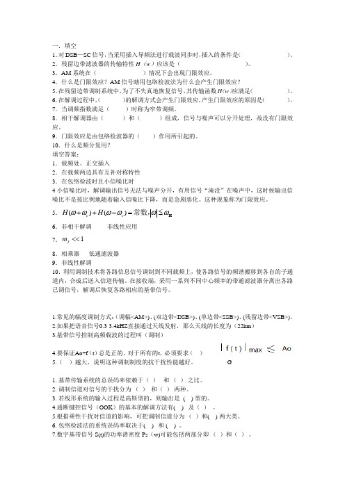
一.填空 1.对DSB —SC 信号,当采用插入导频法进行载波同步时,插入的条件是( )。
2.残留边带滤波器的传输特性H (w )应该是( )。
3.AM 系统在( )情况下会出现门限效应。
4.什么是门限效应?AM 信号瞎用包络检波法为什么会产生门限效应? 5.在残留边带调制系统中,为了不失真地恢复信号,其传输函数H (w )应满足( )。
6.在解调过程中,( )的解调方式会产生门限效应,产生门限效应的原因是( )。
7.当调频指数满足( )时称为窄带调频。
8.相干解调器由( )和( )组成,信号与噪声可以分开处理,故没有门限效应。
9.门限效应是由包络检波器的( )作用所引起的。
10.什么是频分复用? 填空答案:1.载频处、正交插入2.在载频两边具有互补对称特性 3.在包络检波时且小信噪比时4小信噪比时,解调输出信号无法与噪声分开,有用信号“淹没”在噪声中,这时候输出信噪比不是按比例地随着输入信噪比下降,而是急剧恶化。
这种现象称为门限效应。
5.H ()()c c H H ωωωωωω++-=≤常数, 6.非相干解调 非线性应用 7.1f m <<8.相乘器 低通滤波器 9.非线性解调 10.利用调制技术将各路信息信号调制到不同载频上,使各路信号的频谱搬移到各自的子通道内,合成后送入信道传输。
在接收端,采用一系列不同中心频率的带通滤波器分离出各路已调信号,解调后恢复各路相应的基带信号。
1.常见的幅度调制方式:(调幅<AM>)、(双边带<DSB>)、(单边带<SSB>)、(残留边带<VSB>)。
2.如果把语音信号0.3-3.4kHZ 直接通过天线发射,那么天线的长度为(22km ) 3.基带信号控制高频载波的过程叫(调制)4.要保证Ao+f (t )总是正的,对于所有的t ,必须要求( )5.( )越大,说明这种调制制度的抗干扰性能越好。
无线通信技术-第三章

16
3.4 三种基本传播机制
• 反射:当电磁波遇到比波长大得多的物体 时发生反射,如地球表面、墙面等;
• 绕射:当接收机和发射机之间的无线路径 被尖锐的边缘阻拦时发生绕射,由阻挡表 面产生的二次波散布于空间,甚至到达阻 挡体的背面,导致波围绕阻挡体产生弯曲;
• 散射:当波穿行的介质中存在小于波长的 物体并单位体积内阻挡体的个数非常巨大 时,将发生散射,如树叶、街道标志等;
2
远场电场辐射 部分的幅度
13
Pr d Pd Ae
2 PG G t t r
4 d
2
Gr 2 Ae 4
图3-4 在自由空间中,从一个 全向点源发出的能流密度情况
14
如果接收天线建模成接收机的一个匹配阻抗 负载,那么接收天线将会感应出一个均方根 电压进入接收机,它是天线中开路电压的一 半(没有负载时,均方根电压等于开路电 压)。接收功率为:
G
4 Ae
2
c 2 c f c
路径损耗:表示信号的衰减,定义为有效
发射功率与接收功率之间的比值,单dB 10log 10log t r 4 2 d 2 Pr
7
路径损耗也可以不包括天线增益,即假设天 线具有单位增益:
23
2. 布儒斯特角
P
r sini
r cos2i
r sini r cos2i
电磁波投射到介质分界面而不发生反射时的
角度,只发生在水平极化时,其反射系数为 0。 当第一介质为自由空间,第二介质相对介电 常数为εr时,布儒斯特角满足:
sin B
1
r 1
r sini r cos 2 i r cos 2i r cos 2i
无线通信原理与应用第三章

Scattering:occurs when the medium through which the wave travels consists of objects with dimensions that are small compared to the wavelength, and where the number of obstacles per unit volume is large.
Chapter 3: Mobile Radio Propagation:
Large-Scale Path Loss
23.06.2020
.
1
3.1 Introduction to Radio wave Propagation Small-scale and large-scale fading
23.06.2020
: The wavelength in meters.
d: distance in meters L: The miscellaneous losses L (L>=1) are usually due to transmission line attenuation, filter losses, and antenna losses in the communication system. L=1 indicates no loss in the system hardware.
23.06.2020
.
6
9dBi antenna & 3dBi antenna
无线通信原理与应用课程教学大纲
《无线通信原理与应用》课程教学大纲一、课程基本信息1、课程代码:IE3082、课程名称:无线通信原理与应用/ Wireless Communications and Applications3、学时/学分:54/34、先修课程:通信原理5、面向对象:大学本科3、4年级6、开课院(系)、教研室:电子工程系无线通信技术研究所7、教材、教学参考书:1), “Wireless Communications: Principles and Practice, Second Edition”, by Theodore S. Pappaport. Prentice Hall, 2002,2), “Wireless Communications and Networking”, by John W. Mark Weihua Zhuang, Prentice Hall 2003.二、课程性质和任务本课程主要介绍现代无线通信技术的基本技术及相关系统,涉及内容包括各类无线通信系统中出现的基础概念、重要的无线通信标准、及相关技术发展趋势。
课程以概念介绍为主,结合实际系统为例展开讨论。
无线系统设计基本概念:信道分配、切换、分集效率、干扰、频率复用、系统容量规划、大尺度衰落;路径损耗、小尺度衰落、多径、反射、折射、衍射、阴影效应、空时信道、微蜂窝/室内传播。
2G/3G系统基本概念:WCDMA、CDMA2000、GPRS、EDGE;无线局域网系统基本概念:IEEE802.11a/b、HiperLAN,Bluetooth、无线城域网。
三、教学内容和基本要求第一章介绍 (3)1,无线通信系统的演进;2,典型无线系统;3,未来无线通信系统的发展趋势.第二章无线传播(6)1,大尺度衰落(3)无线电波传播特性介绍;自由空间模型;反射;折射;散射;实际路径衰落模型;室外传播模型;室内传播模型:2,小尺度衰落(3)小尺度多径传播;多径信道德脉冲冲击响应;小尺度多径的测量;移动多径信道模型;小尺度衰落的分类;Rayleigh和Rice衰落发布模型;统计模型;多径衰落因子理论。
第三章 TD-LTE系统关键技术

第三章 TD-LTE系统关键技术TD-LTE是TDD版本的LTE技术,相比3GPP之前制定的技术标准,其在物理层传输技术方面有较大的改进。
为了便于理解TD-LTE系统的核心所在,本章将重点介绍TD-LTE 系统中使用的关键技术,如多址接入技术、多天线技术、混合自动重传、链路自适应、干扰协调等。
希望读者通过本章的阅读,对TD-LTE的物理层技术有一个全面的了解。
3.1 TDD双工方式TDD(Time Division Duplexing)时分双工技术是一种通信系统的双工方式,与FDD相对应。
在TDD模式下,移动通信系统中的发送和接收位于同一载波下的不同时隙,通过将信号调度到不同时间段传输进行区分。
TDD模式可灵活配置于不对称业务中,以充分利用有限的频谱资源。
在原有的模拟和数字蜂窝系统中,均采用了FDD双工/半双工方式。
在3G的三大国际标准中,WCDMA和CDMA2000系统也采用了FDD双工方式,而TD-SCDMA系统采用的是TDD双工方式。
FDD双工采用成对频谱(Paired Spectrum)资源配置,上下行传输信号分布在不同频带内,并设置一定的频率保护间隔,以免产生相互间干扰。
由于TDD双工方式采用非成对频谱(Unpaired Spectrum)资源配置,具有更高的频谱效率,在未来的第四代移动通信系统IMT-Advanced中,将得到更广泛的应用,满足更高系统带宽的要求。
基于TDD技术的TD-LTE系统,与FDD方式相比,具有以下优势:(1)频谱效率高,配置灵活。
由于TDD方式采用非对称频谱,不需要成对的频率,能有效利用各种频率资源,满足LTE系统多种带宽灵活部署的需求。
(2)灵活地设置上下行转换时刻,实现不对称的上下行业务带宽。
TDD系统可以根据不同类型业务的特点,调整上下行时隙比例,更加灵活地配置信道资源,特别适用于非对称的IP型数据业务。
但是,这种转换时刻的设置必须与相邻基站协同进行。
无线通信原理与应用(第二版)(1)
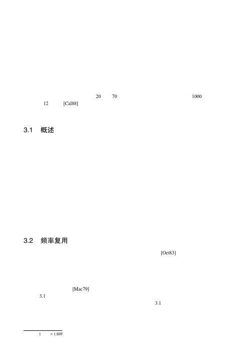
(3.1)
共同使用全部可用频率的 N 个小区称为一个簇。如果簇在系统中复制了 M 次,则双向信道的 总数 C 可以作为容量的一个度量:
解: 已知:总带宽 = 33 MHz 信道带宽 = 25 kHz × 2 单向信道 = 50 kHz/ 双向信道 总的可用信道 = 33 000/50 = 660 个信道
(a) N = 4 每个小区的信道数目 = 660/4 ≈ 165 个信道
(b) N = 7 每个小区的信道数目 = 660/7 ≈ 95 个信道
3.2 频率复用
蜂窝无线系统依赖于整个覆盖区域内信道的智能分配和复用[Oet83]。每个蜂窝基站都分配一 组无线信道,这组信道用于称为“小区”的一个小地理范围内,该信道组所包含的信道不能在其相 邻小区中使用。基站天线的设计要做到能覆盖某一特定小区。通过将覆盖范围限制在小区边界以内, 相同的信道组就可用于覆盖不同的小区。要求这些同信道组的小区两两之间的距离足够远,从而使 其相互间的干扰水平在可接受的范围内。为整个系统中的所有基站选择和分配信道组的设计过程称 为频率复用或频率规划[Mac79]。
为了充分利用无线频谱,必须要有一个能实现既增加用户容量又以减小干扰为目标的频率复用 方案。为了达到这些目标,已经发展了各种不同的信道分配策略。信道分配策略可以分为两类:固 定的和动态的。选择哪一种信道分配策略将会影响系统的性能,特别是在移动用户从一个小区切换 到另一个小区时的呼叫处理方面([Tek91], [LiC93], [Sun94], [Rap93b])。
无线通信技术的原理解析与应用
无线通信技术的原理解析与应用无线通信技术是指通过无线信道进行信息传输的一种通信方式。
它在现代社会中起着至关重要的作用,被广泛应用于手机、电视、无线网络等各个领域。
本文将从原理解析和应用两个方面,详细介绍无线通信技术。
一、原理解析1. 电磁波的传播原理:无线通信技术依赖于电磁波的传播。
电磁波是由电场和磁场相互作用而产生的,可以在空气、真空和介质中传播。
它具有频率和波长的特性,根据不同的频率分为无线电波、微波、红外线、可见光等。
2. 调制与解调:无线通信技术中的信息传输需要借助调制与解调技术。
调制是将要传输的信息信号转换成具有较高频率的载波信号,在传输过程中通过改变载波信号的某些特性来携带信息。
解调则是将接收到的调制信号恢复成原始的信息信号。
3. 频谱分配:为了避免不同频率的无线通信设备之间的干扰,频谱分配成为必要的步骤。
不同国家和地区的频谱管理机构根据通信需求,将频率划分给不同的无线通信系统,确保它们之间互不干扰。
4. 信道编码:为了提高信息传输的可靠性和安全性,无线通信系统会采用信道编码技术。
通过在信号中添加冗余信息,以便在传输过程中纠正和检测错误。
常见的信道编码技术包括纠错码、交织技术等。
二、应用1. 手机通信:无线通信技术最常见的应用就是手机通信。
通过手机网络,人们可以进行语音通话、短信、互联网访问等功能。
无线通信技术的快速发展使得手机通信变得更加便捷和高效。
2. 无线网络:无线通信技术还广泛应用于无线网络。
无线局域网(WLAN)通过无线路由器将互联网连接扩展到无线终端设备,使得人们可以在任何地方获得网络连接。
此外,无线通信技术也支持移动通信网络(如4G、5G),为人们提供高速的移动上网体验。
3. 电视和广播:无线通信技术在电视和广播领域也有重要的应用。
无线电广播通过无线电波将音频信号传输到收音机,并使得人们可以收听广播节目。
电视信号的传输也依赖于无线通信技术,使得人们可以观看电视节目。
4. 无线传感器网络:无线传感器网络(WSN)是由大量分布式传感器节点组成的网络。
《无线通信》课程教学大纲

(4) MIMO与空时处理;(5) 全数字接收机;(6) 通信系统的主要性能指标。
2.重、难点提示(1) 重点是双工、复用、多址;(2) 难点是通信系统的主要性能指标。
第二章通信信号与系统的表征(4学时)1.教学内容(1) 带通信号及系统的复基带表示;(2) 信号空间表示法;(3) 随机信号。
2.重、难点提示(1) 重点是带通信号的复基带表示、线性带通系统的复基带表示;(2) 难点是信号波形的矢量表示、平稳与周期平稳随机过程。
第三章无线传输信道(4学时)1.教学内容(1) 传播模型;(2) 平坦衰落信道;(3) 频率选择性衰落信道;(4) 方向性衰落信道;(5) 衰落信道仿真。
2.重、难点提示(1) 重点是确定线性时变信道的系统函数、随机线性时变信道分类;(2) 难点是双向冲激响应、MIMO信道响应矩阵。
第四章无线信道容量(6学时)1.教学内容(1) 信道模型;(2) 信息度量;(3) 加性高斯噪声信道容量;(4) 平坦衰落信道容量;(5) MIMO信道容量。
2.重、难点提示(1) 重点是离散输入连续输出信道、离散时间AWGN信道;(2) 难点是带限白高斯噪声信道、香农信道容量公式。
第五章数字调制信号及其功率谱密度(4学时)1.教学内容(1) 奈奎斯特脉冲成形;(2) 数字调制信号表示;(3) 调制信号功率谱。
2.重、难点提示(1) 重点是无记忆调制信号、有记忆调制信号;(2) 难点是调制信号复包络的功率谱密度、完全响应CPM信号功率谱。
第六章平坦衰落信道数字传输的接收与性能(4学时)1.教学内容(1) 接收信号的矢量表示;(2) 一般矢量信道中的检测;(3) AWGN信道中相干接收性能;(4) AWGN信道中非相干接收性能;(5) AWGN信道中CPM信号的检测。
九、选用教材和参考书目[1]《现代无线通信原理》(第一版),林基明编,科学出版社,2015年;[2]《大话无线通信》(第一版),丁奇编,人民邮电出版社,2010年;[3]《移动通信技术》(第二版),高健编,机械工业出版社,2012年;[4]《移动通信技术》(第一版),宋拯编,北京理工大学出版社,2012年;[5]《无线通信原理与应用》(第二版),拉帕波特编,电子工业出版社,2012年;[6]《无线移动通信系统》(第四版)(英文版),Dharma P. Agrawal(D. P. 阿格拉沃尔),[美] Qing-An Zeng(曾庆安)著,谭明新改编,电子工业出版社,2016年;[7]《无线通信原理与应用》(第一版),石明卫编,人民邮电出版社,2014年。
通信原理第三章 ppt课件
制某载波的过程 。
通信原理第三章
3、调制的作用
★(1)将基带信号变成适合在信道中传输 的已调信号
★(2)实现信道的多路复用 (3)改善系统的抗噪声性能 (4)改变信号占用的带宽
通信原理第三章
4、调制的分类
连续波调制 (载波为正弦波)
振幅调制(AM, DSB ,SSB,VSB) 模拟调制 频率调制(FM )
(1)最直接的方法——滤波法:
将不含直流分量的基带信号m(t)和载波信号经乘法器后 得到双边带信号DSB,再通过一个单边带滤波器就得 到需要的单边带SSB信号。
m(t )
h (t )
S SSB ( t )
A cos c t
单边带调制 通信原的理第一三章般模型
单边带调制(SSB)的一般模 型
从图中看,SSB与DSB好象没什么不同, 但两者的h(t) 不同。DSB 的h(t) 要求保 留两个边带信号;而SSB 的h(t)只要求 保留一个而且只能保留一个边带信号。
1 2
t
- c
0
通信原理第三章
A0
c
调幅AM信号
由图可见: (1)波形包络与输入基带信号m(t)成正比 (2)频谱具有上、下对称的两个边带 (3)频谱中心含离散载频分量,它并不携带信息 (4)要使调幅波的包络波形与基带信号波形相同, 则一定要满足两个条件: a、对所有的t的值|m(t)|max≤ A0,否则会过调制 b、载波频率必须高于基带信号的最高频率
线性调制器的一般模型
输出信号的一般表达式:
时域: s m ( t ) m ( t ) A co 0 t h ( s t )
且 m(t) M()
无线通信原理与应用-3.5 提高蜂窝系统容量
电气工程学院 通信工程系
无线通信原理与应用
Wireless Communications Principles and Practice
例题
•见右图。假设不管小区大小,每个基站都 使用60个信道。如果原来的小区每个半径 为lkm,每个微小区的半径为0.5km,计算 以A为中心的3km×3km的正方形区域所含 有的信道数。 •(a)不使用微小区, •(b)用了图2.9中标有字母的微小区, •(c)原来 的所有基站都用微小区来代替。
1. 小区分裂:通过增加基站的数量来增加系统容量;不降低中继效率,使得基站能监 视与微小区有关的所有切换,从而减小MSC的计算量
2. 裂向(划分扇区):用有方向的天线来进一步控制干扰和信道的频率复用;依靠基 站天线的定位来减小同频干扰以提高系统容量;降低了中继效率;
3. 覆盖区域逼近(分区微小区):微小区概念将小区覆盖分散,将小区边界延伸到难 以到达的地方;依靠基站天线的定位来减小同频干扰以提高系统容量;不降低中继
小区分裂应用中需要注意的问题
注意点1:不是所有的小区都同时分裂。对于服务提供 者来说,要找到完全适合小区分裂的确切时期通常很困 难。因此,不同规模的小区将同时存在。
注意点2:保持同频小区间所需的最小距离,因而频率 分配变得更复杂。
电气工程学院 通信工程系
无线通信原理与应用
Wireless Communications Principles and Practice
因而能提高系统容量。
II. 通过设定比原小区半径更小的新小区和在原有小区间安置这些小区(叫 做微小区),使得单位面积内的信道数目增加,从而增加系统容量。
【无线通信课后习题】
【无线通信课后习题】习题2.61、 W-CDMA 保证对GSM、IS-136、PDC、TDMA技术以及多种2.5G TDMA技术的后向兼容。
它保存了网络构造和比特级的GSM数据封装通过新的CDMA空中接口标准提供了更强的网络才能和带宽。
2、W-CDMA支持的速率到达每用户 2.048Mbps,用户可以获得高质量数据、多媒体、流媒体音频和视频以及播送业务。
将来的W-CDMA将为静态用户提供8Mbps以上的速率,并且提供公共网络和私有网络的特性,支持视频会议和虚拟归属环境。
3、如今W-CDMA标准已经成为3GPP世界组织的研究重点,而且全球范围内的其他3GPP组织中的制造商、运营商、工程师以及政府都在研究W-CDMA。
4、 W-CDMA标准需要完全更换基站的射频设备,其部署是一个渐进的、长期的过程,在其部署完成之后就不在需要后向兼容GSM/GPRS、IS-136、PDC 以及EDGE5、3G W-CDMA的空中接口是“永远在线”的,计算机、娱乐设备、可以共用同一个无线网络,在任何时间地点接Inter.无线通信原理及应用第三章课后作业3.6题 (a).簇的大小为N,位于效劳小区边缘的挪动台与第一层同频小区的间隔 R N=1时,有i=1,j=0,R=(2R+2R*2+2*(25R) (R)222)/67+3)/3=1.88RD=N*R=1.732R第一层有6个同频小区 N=3时,有i=1,j=1,R=(4R+2R+2*(3R353R)2+2+2*(R)2+(R)2)/6 2222=(3R+R+R)/3=3.08RD=N*R=3R 第1层有6个同频小区N=4时,有i=2,j=0,R23372*〕+(3R)2+2*R2+(23R)2+2*(3R)2+(R)22222 R=6=7++R=3.54R3D=N*R=3.46R 第1层有6个同频小区N=7时,有i=2,j=1,R=1123275172R〕+(R)+2*(23R)2+(R)2+2*(3R)2+(R)2+(R)2+(R)2222222 6=4.62RD=N*R=4.58R 第1层有6个同频小区N=12时,有i=2,j=2,7R+5R+2*(3R)2+(4R)2+(2R)2+(3R)2R==6.04R6D=N*R=6R 第1层有6个同频小区综上比拟均有R》D(b) 第二层同频小区数位12个,第三层为18个 (c) n=4只考虑第一层的情况,i0=6S(N)nIi0S(N)n=13.5dB N=3时,= Ii0S(N)n=24dB N=4时,=Ii0S(N)n=73.5dB N=7时,= Ii0S(N)n=216dB N=12时,= Ii0考虑第二层,i0=12 S(N)n=0.75dB N=1时,= Ii0S(N)n=6.75dB N=3时,= Ii0S(N)n=12dB N=4时,=Ii0S(N)n=36.75dB N=7时,= Ii0S(N)nIi0S1S第m层有m=ImI主观测试说明,当S/I大于等于18dB时就可以提供足够好的话音质量故,N=1,3时,m=1,其外层的同频小区对挪动台干扰的影响就可以忽略不计; N=4时,m=2,其外层的同频小区对挪动台干扰的影响就可以忽略不计; N=7时,m=5,其外层的同频小区对挪动台干扰的影响就可以忽略不计; N=12时,m=12,其外层的同频小区对挪动台干扰的影响就可以忽略不计。
无线通信原理与应用第二版课后练习题含答案
无线通信原理与应用第二版课后练习题含答案第一章绪论选择题1. 下列哪一种无线通信技术的频率最低?A. 蓝牙B. Wi-FiC. ZigbeeD. RFID答案:D判断题1. 无线通信技术只在近年来快速发展,以前没有应用历史。
答案:错误第二章无线信道传输基础选择题1. 无线信道传输中出现的信道;随机转换为周期变换的方法被称为:A. 等效周期转换法B. 非等效周期转换法C. 均匀随机交替法D. 非均匀随机交替法填空题1. 在无线传输的环境中,由于信号在其传播过程中将受到反射、衍射等影响,因此信号会受到多个路径的传输,称之为多径效应。
答案:多径效应简答题1. 请简述自由空间传播模型的传输路径特点。
自由空间传播模型的传输路径特点是直线传播。
自由空间传播模型适用于在较为开阔的场合中,由于不具有阻碍、反射、绕射等因素的影响,因此传播损耗小。
但是在实际应用中,很难避免多径效应,在城市等复杂环境中,自由空间传播模型不具有现实意义。
第三章无线传输技术选择题1. 下列哪一种无线传输技术属于固定式通信?A. Wi-FiB. WCDMAC. 链路D. 蓝牙答案:C1. 请简述频分复用的基本概念和特点。
频分复用基本上是通过将一条信道分为多个子信道来实现的,每一个子信道都具有不同的载波频率和时间插槽,可以支持多个用户在同一条通信信道中传输信息。
在频分复用中,对于不同频段的信号,发送和接收机通过中继站进行转换。
频分复用技术可以减少重复线路的数量,降低了系统的成本。
同时,它也具有可靠、稳定的传输品质,适用于多种不同的通信标准。
无线通信原理与应用-第三章 网络技术基础
Higher-speed
Speed and Distance of Communications Networks
LAN interconnects devices within a single building or cluster of buildings
LAN usually owned by organization that owns the attached devices
For WANs, most of network assets are not owned by same organization
Characteristics of WANs
Covers large geographical areas Circuits provided by a common carrier Consists of interconnected switching nodes Traditional WANs provide modest capacity
Circuit switching
Dedicated communications path between two stations E.g., public telephone network
Message is broken into a series of packets Each node determines next leg of transmission for each packet
3-1第三章无线通信基本技术(抗衰落技术)

两个极化方向相互正交的天线发出的信号可以具 有独立的衰落特性 极化分集是空间分集的另一变化形式。 所采用的方法是发送端和接收端可以用两个位置 很近但不同极化的天线分别发送和接收信号,以 此获得分集效果。
极化分集
根据电磁波的基本传播机制,水平和垂直极化的多 径分量传播特性是不同的。
由于反射过程与极化方式有关,即使发射天线只发 射单一极化的信号,信道传播特性的影响也会导致 去极化,从而接收机可以接收到两种极化方式不同 的信号。 使用双极化的天线接收两个极化方式的信号,分别 进行信号处理后再合并,即可实现
多径传播和相对运动同时存在,无线链路具有时变的 多径传播特性,这种特性严重影响通信系统的性能和 通信的效果。
导致接收信号严重失真和深度衰落,误码率大大增加。 需要应用信号处理技术改善无线链路性能。 均衡、分集、信道编码三种技术,可以用来改进接收 信号质量和链路性能
均衡技术一般用横向滤波技术实现,用以补
宏分集用位于不同地点的多个接收机和发射机进
行处理,也称为“多基站”分集。 宏分集用于消除阴影衰落。
微分集是只用一个接收机实现,
微分集用于抗多径衰落。
9
宏分集
2 分集技术
分集技术对信号的处理包含两个过程:
首先是分散传输,使接收端能获得多个统计
独立携带同一信息的衰落信号;
然后对它们进行集中处理使信噪比得到改善,
CDMA接收机通过合并多径信号来改善接收信号的信噪 比。 通过多个相关检测器获取多径信号中的各路信号,并把 它们合并在一起。
当多径时延差超过一个码片周期时,多径信号可以看成 是不相关的。
Rake接收机原理图
Z1
无线通信原理与应用
无线通信主要包括微波通信和卫星通信。
微波是一种无线电波,它传送的距离一般只有几十千米。
但微波的频带很宽,通信容量很大。
微波通信每隔几十千米要建一个微波中继站。
卫星通信是利用通信卫星作为中继站在地面上两个或多个地球站之间或移动体之间建立微波通信联系。
无线通信原理1,首先要把要传输的信号,调制到载波上。
由于一般信号频率较低,不易发射,而载波频率较高,容易发射。
所以第一步工作就是调制。
调制的方法有三种:(1)调幅,把信号加到载波上,使载波的振幅跟随信号改变(2)调频,把信号加到载波上,使载波的频率跟随信号改变(3)调相,把信号加到载波上,使载波的相位角跟随信号改变。
调制方法,有模拟信号调制和数字信号调制两种。
2,以调制的信号,视发射的远近,还要加以放大。
接着送到开放电路发射出去。
形成无线电波。
3,接收。
在异地利用电谐振,把空中的已调制的电磁波接收到来[往往很微弱],加以放大,然后检出信号波,[或再放大],再执行还原。
无线电通信原理,无论具体执行时,千变万化,其原理比遵循上述三点。
无线通信应用(1)4G第四代移动电话行动通信标准,指的是第四代移动通信技术,外语缩写:4G。
该技术包括TD-LTE和FDD-LTE两种制式(严格意义上来讲,LTE 只是3.9G,尽管被宣传为4G无线标准,但它其实并未被3GPP认可为国际电信联盟所描述的下一代无线通讯标准IMT-Advanced,因此在严格意义上其还未达到4G的标准。
只有升级版的LTE Advanced才满足国际电信联盟对4G的要求)。
4G是集3G与WLAN于一体,并能够快速传输数据、高质量、音频、视频和图像等。
4G能够以100Mbps 以上的速度下载,比目前的家用宽带ADSL(4兆)快25倍,并能够满足几乎所有用户对于无线服务的要求。
此外,4G可以在DSL和有线电视调制解调器没有覆盖的地方部署,然后再扩展到整个地区。
很明显,4G有着不可比拟的优越性。
图7 4G迅速火爆(2)ZigBee技术ZigBee技术主要用于无线域网(WPAN),是基于IEE802.15.4无线标准研制开发的,是一种介于RFID和蓝牙技术之间的技术提案,主要应用在短距离并且数据传输速率不高的各种电子设备之间。
《5G移动通信系统及关键技术》第03章 5G无线技术3.2-3.3

3.2.1 灵活双工技术
载波聚合(Carrier Aggregation,CA)——将多个不同频率(或者相同) 的载波聚合成一个更宽的频谱,同时也可以把一些不连续的 频谱碎片聚合到一起,从而达到提高带宽的效果 载波聚合、非载波聚合都可以采用灵活双工技术。 载波聚合应用场景中,网络可将原用于上行传输的频带用于 下行传输,并将该频带配置成辅载波辅小区; 非载波聚合应用场景中,网络可将原用于上行传输的频带用 于下行传输,并将该频带和上行频带配置成配对的频带。
1-17
3.2.2 同频同时双工
双工干扰分两类:
➢ 发射天线到接收天线的直达波 ➢ 经过多物体反射的多径到达波
全双工技术包括两方面:
➢ 全双工系统的自干扰抑制技术 ➢ 组网技术
双工干扰消除越多,系统频谱效率增益越大, 双工干扰被完全消除,则系统容量提升1倍。
1-18
3.2.2 同频同时双工
3、同时同频全双工中的干扰消除技术
简单,用户间干扰较小,但是受传输中信道衰落的影响比较 大。 – 间隔扩展子载波(Comb Spread Subcarriers),其特点是 通过频域扩展,增加频率分集,从而减少了信道衰落的影响。
多载波技术
(a) 分组子载波方式 (b) 间隔扩展thogonal Frequency Division Multiplexing)技 术是主流无线通信所采用的信号形式
Duplex,CCFD ——通信双方能够使用相同的时间、相同的频 率,同时发射和接收无线信号,从而将频谱效 率翻倍。 同频同时全双工的关键在于干扰的有效消除。
1-16
3.2.2 同频同时双工
2、同频同时全双工节点
节点基带信号经射频调制,从发射天线发出,而接收天线正在 接收来自期望信源的通信信号。
第三章 模拟调制系统(通信原理)

例题
21
单边带调幅—SSB
DSB信号虽然节省了载波功率,调制效率提高了, 但频带宽度仍是调制信号带宽的两倍,同AM信号 DSB信号的上、下两个边带是完全对称的,它们都 携带了调制信号的全部信息 仅传输双边带信号中一个边带。 节省发送功率,节省一半传输频带。 产生SSB信号的方法:
c
下边带(LSB)调制
23
SSB—滤波法
SSB信号的频谱
SSSB ( ) S DSB ( ) H
SDSB
上边带频谱图:
c
0
c
H USB
c
0
S USB
c
c
0
c
24
SSB—滤波法(技术难点)
用滤波法形成SSB信号的技术难点是:
滤波法产生SSB的多级频率搬移过程
26
SSB—相移法
1 H ( ) sgn( c ) sgn( c ) 2
S SSB ( ) 1 M ( c ) M ( c )H ( ) 2 1 M ( c ) sgn( c ) M ( c ) sgn( c ) 4 1 M ( c ) sgn( c ) M ( c ) sgn( c ) 4 1 M ( c ) M ( c ) 4 1 M ( c ) sgn( c ) M ( c ) sgn( c ) 4
滤波法 相移法
22
SSB—滤波法
m t
sDSB t
H
sSSB t
载波 c t
- 1、下载文档前请自行甄别文档内容的完整性,平台不提供额外的编辑、内容补充、找答案等附加服务。
- 2、"仅部分预览"的文档,不可在线预览部分如存在完整性等问题,可反馈申请退款(可完整预览的文档不适用该条件!)。
- 3、如文档侵犯您的权益,请联系客服反馈,我们会尽快为您处理(人工客服工作时间:9:00-18:30)。
Pt 2 PL(dB) 10log 10log[ ] 2 2 Pr (4) d
PL(dB) 32.44 20lg f 20lg d
2014-11-12
(f:MHz,d:km)
8
The far-field region of a transmitting antenna
• The Friis free space model is only a valid predictor for Pr for values of d, which are in the far-field of the transmitting antenna. • The far-field of a transmitting antenna is defined as the region beyond the far-field distance df , which is related to the largest linear dimension of the transmitter antenna aperture and the carrier wavelength. The farfield distance is given by
2
3.2 Free Space Propagation Model
In free space, the received power is predicted by Firiis Equ. 2
Pr ( d) P t Gt Gr
4 2 d2L
Pr(d): Received power with a distance d between Tx and Rx Pt: Transmitted power Gt: Transmitting antenna gain Gr: Receive antenna gain : The wavelength in meters. d: distance in meters L: The miscellaneous losses L (L>=1) are usually due to transmission line attenuation, filter losses, and antenna losses in the communication system. L=1 indicates no loss in the system hardware.
d PL(d )[dB] PL(dB) X PL(d 0 ) 10n log( ) X d0
2014-11-12
14
Log-normal Shadowing
2014-11-12
15
Determination of Percentage of Coverage Area
df
2D 2
d f D and d f
• To be in the far-field region, d must satisfy
d df
2014-11-12
9
The Reference Distance
• It is clear that equation does not hold for d=0. For this reason, largescale propagation models use a known received power reference point. The received power, Pr(d), at any distance d>d0, may be related to Pr at d0.
• If Pr is in units of dBm or dBW, the received power is given by
d0 2 Pr (d ) Pr (d 0 )( ) d
d d0 d f
d0 Pr (d ) 10 log( Pr ( d 0 )) 20 log( ) d d 0 d f d
2014-11-12 6
9dBi antenna & 3dBi antenna
2014-11-12
7
Path Loss
• The path loss, which represents signal attenuation as a positive difference (in dB) between the effective transmitted power and the received power. • The path loss for the free space model when antenna gains are included is given by quantity measured in dB, is defined as the
2014-11-12
3
3.3 The three Basic Propagation Mechanisms
Reflection: occur from the surface of the earth and from
buildings and walls.
Diffraction:occurs when the radio path between the transmitter
and receiver is obstructed by a surface that has sharp irregularities (edges).
Scattering:occurs when the medium through which the wave travels consists of objects with dimensions that are small compared to the wavelength, and where the number of obstacles per unit volume is large.
• EIRP: Effective Isotropic Radiated Power Represents the maximum radiated power available from a transmitter in the direction of maximum antenna gain, as compared to an isotropic radiator. • ERP: Effective Radiated Power ERP is used instead of EIRP to denote the maximum radiated power as compared to a half-wave dipole antenna (instead of an isotropic antenna). In practice, antenna gains are given in units of dBi (dB gain with respect to an isotropic sourse) or dBd (dB gain with respect to a half-wave dipole)
If n=4,log(d/d0)=75.5/40=1.8875,d=7718m
2014-11-12
13
Log-normal Shadowing
The model in Equation (3.11) does not consider the fact that the surrounding environmental clutter may be vastly different at two different locations having the same T-R separation. This leads to measured signals which are vastly different than the average value predicted by Equation (3.11).
PL(d ) 10log
Pt d PL(d0 ) 20log( ) Pr d0
2014-11-12
10
3.4 Link budge design using path loss model
Log-distance path loss model
Both theoretical and measurement-based propagation models indicate that average received signal power decreases logarithmically with distance, whether in outdoor or indoor channels. The average large-scale path loss for an arbitrary T-R separation is expressed as a function of distance by using path loss exponent n.
Ri
R0
dA
2014-11-12
16
U(r) as a function of probability of signal above threshold on the cell boundary.
2014-11-12
17
Example 2
• A local average signal strength field measurements , the measured data fit a distant-dependent mean power law model having a log-normal distribution about the mean. Assume the mean power law was found to be Pr (d ) d 3.5 .If a signal of 1mW was received at d0=1m from the transmitter, and at a distance of 10m, 10% of the measurements were stronger than -25dBm, define the standard deviation, ,for the path loss model at d=10m.
