支井河大桥施工过程照片
大小井上飘彩虹——大小井特大桥合龙“世界桥梁博物馆”再添新员

大小井上飘彩虹文/贵州省公路局 张祥兵随着最后一节钢管吊装就位,6月30日上午11时许,横跨贵州省罗甸县沫阳镇董当乡大井村大井河上空的平塘至罗甸高速公路大小井特大桥主拱圈顺利合龙,成为目前世界最大跨径山区上承式钢管混凝土拱桥。
贵州首座完全自主建设的世界级大桥大小井风景区上空,两山相峙。
青山绿水之间,横跨南北的大小井特大桥凌空飞架,宛若一道绚丽的彩虹。
作为贵州余庆至安龙高速公路平塘至罗甸段的控制性工程,大小井特大桥自2016年6月29日开工建设,合同工期38个月,概算投资3.7亿元。
大桥全长1.5公里,主桥主跨450米,引桥采用40米装配式组合T梁建设,是世界最大跨径山区上承式钢管混凝土拱桥。
大桥桥台所在山坡峰顶与河底——大小井特大桥合龙 “世界桥梁博物馆”再添新员相对高差约250米,是名副其实的空中“天路”。
目前,“世界桥梁博物馆”中,贵州已经汇集了北盘江大桥、清水河大桥、鸭池河大桥等世界级桥梁,这些超级工程的背后都有中国交建等企业的投入。
不同的是,大小井特大桥由贵州省公路开发有限责任公司投资建设,贵州桥梁建设集团有限责任公司、贵州路桥集团有限公司联合施工,是贵州本土企业完全自主建设的第一座世界级大桥。
“平罗高速大小井特大桥合龙成功!”6月30日,随着贵州省交通运输厅总工程师潘海宣布,“贵州桥”又一次刷新世界纪录,在“世界桥梁博物馆”中,贵州再收录一件新“藏品”。
“世界级难题”成功破解“山区建桥,首选拱桥。
但拱桥的施工工艺比斜拉桥更复杂。
”贵州桥梁建设集团有限责任公司总工程师张胜林说,作为我国典型的高山峡谷大跨度钢管拱桥和世界同类型的桥梁之最,大小井特大桥结构、技术复杂,质量要求高,施工难度更大。
拱座施工现场地形陡峭,边坡开挖高度高,开挖方量大,大体积混凝土温度控制技术难度大,拱脚预埋件安装精度要求高;缆索吊机安装施工主塔拼装高度高,主索安装跨度大,施工安全风险高;主拱安装施工拱肋纵向运输距离长,吊装重量大,主拱对接精度、线形及高程控制要求高,主拱悬拼施工时间长,斜拉扣挂施工难度高;山区机制砂C60自密实混凝土技术难度高,混凝土顶升度高……张胜林一口气数出一串大小井特大桥的难点,随着大桥的合龙,这些难点被建设者们一一破解。
支井河大桥汇报资料

-15.8
-14.0
-16.9
-18.4
-21.5
-12.7
-15.6
-12.2
-12.4
-10.4
-8.8
-9.1
ቤተ መጻሕፍቲ ባይዱ
-7.3
恒载+挂 车
-15.0 -10.8 -12.9 -14.7 -15.2 -16.0 -13.2 -12.6 -9.6 -8.1
从上面的计算结果可看出 ,按应力叠加法,在考虑收缩 徐变的影响下,使用阶段,主 拱圈钢管的最大压应力达到 260.6Mpa,钢材距其设计强度 320Mpa尚有一定的距离。
第一阶振型
第二阶振型
钢管砼拱桥面外和面内一阶计算频率
桥名 梅溪河大桥
主跨 288m
拱桥类型 上承式钢管砼桁架拱
基频(Hz)
面外
面内
0.20
0.45
巫峡长江大桥
460m
中承式钢管砼桁架拱
0.17
0.35
支井河特大桥
430m
上承式钢管砼桁架拱
0.22
0.47
丫髻沙大桥
360m
中承式钢管砼桁架拱
0.33
0.44
主钢管的横连
组拼主拱肋片
三、钢管混凝土的基本性能
钢管混凝土是指在钢管 中填充混凝土而形成的构 件,钢管混凝土轴心受压 时产生紧箍效应,是钢管 混凝土具有特殊性能的基 本原因。
钢管混凝土构件在轴心 压力作用下,钢管和核心 混凝土都处于三向应力状 态下,与单向受压时不同 ,其性能发生了改变。
在三向应力状态(纵向受 压而环向受拉)下,钢材的 屈服强度fy降低,而极限应 变却增大;随着紧箍力的增 大,混凝土的抗压强度提高 ,弹性模量也提高,塑性变 形能力也大大增加。
拱桥的发展
7)跨度≥300 m的混凝土拱桥,目前仅有6座,其技术还处于发展之中
190+552+190 100+550+110 518 504 503 485 460 100+450+100 177+428+177 88+102+420+102+8 8
完成时 间 2009 2003 1976 1931 1932 2009 2005 2009 2007 2007
备注
连续钢桁系杆拱 中承式,刚箱 上承二铰钢桁拱 中承二铰钢桁拱 中承钢桁拱 中承双肢钢箱拱 连续刚架钢桁拱 中承刚构、钢桁拱,连续钢箱系杆 拱
拱桥的发展史大瑞铁路怒江四线特大桥第二部分拱桥的发展方向石拱桥1采用天然材料具有独特的美学价值2造价昂贵新建的石拱桥极少大多在公园或风景区中3大量现存石拱桥的维护改造和迁移成为国外研究的重点4劳动生产率低支架费用大对地质条件要求高5经济性较其它桥梁已从过去的优势变为劣势在我国石拱桥修建日趋减少混凝土拱桥1以廉价抗压强度高的混凝土为主配置少量钢筋抵抗拉应力结构合理2自重大施工过程中需大量的施工设备与临时设施3人工费用高经济性低当跨径增大时这个问题愈显得突出4钢管混凝土拱桥的出现抢占了钢筋混凝土拱桥的应用范围5跨度在200m以下的混凝土拱桥已有大量修建技术已日趋成熟经济性好6跨度200m时其技术难度较大其竞争力要依具体的工程情况而定7跨度300m的混凝土拱桥目前仅有6座其技术还处于发展之中钢拱桥1材料抗压强度高自重小架设方便跨越能力大2拱以受压为主稳定问题突出高强材料的性能不能得到充分发挥3与斜拉桥相比其施工架设困难且费用高4对地质条件要求较高后期养护与维修费用高钢管混凝土拱桥1套箍作用大大提高了混凝土的塑性性能2混凝土内填于钢管之内增强了钢管的管壁稳定性3中国已修建了大量的钢管混凝土拱桥最大跨径已达到530m泸州合江长江一4该桥型要达到500m和500m以上并不是太困难的事情5更大跨度需要与斜拉桥悬索桥进行技术和经济比较确定组合体系拱桥1满足桥梁景观要求2满足结构刚度的要求3把两种不同的桥式结构从造型和受力方面进行组合4主要有拱与连续梁刚构拱与斜拉桥拱与t构桥拱与悬索桥的组合5适宜建在对美观要求较高的地区51组合体系拱桥拱连续刚构组合体系将连续刚构桥和拱桥两种结构结合在一起能有效控制连续梁刚构后期徐变变形具有跨越能力强结构刚度大施工方便等优点
《公路桥涵设计通用规范》修订情况介绍-160423沈阳

体现了近年来工程设计理念的变化
1 总则
1.0.2 本规范适用于新建和改建各等级公路桥涵的设计。
修改条文。 结构设计——设计
1.0.3 公路桥涵结构的设计基准期为100年。 保留条文。 桥梁上的可变作用是随时间变化的,其统计分析要用随机过程概率模型来描述。 随机过程所选择的时间域即为基准期。
1 总则
明石海峡大桥 虎门二桥泥洲航道桥 西堠门大桥 大海带桥 Gwangyang 润扬长江大桥 南京长江四桥 洞庭湖大桥 Humber Bridge 江阴长江大桥
1
修订背景
我国桥梁建设成就 世界排名前10位的拱桥
序号 1 2 3 4 5
桥
名
主 跨(m) 552 550 530 518 504
国家 中国 中国 中国 美国 美国
2015版《公路桥涵设计通用规范》
宣 贯 解 读
中交公路规划设计院有限公司标准规范研究室主任 规范编写组 冯苠
2016年4月23日
汇 报 提 纲
一、总体情况介绍
二、主要修订内容
三、具体修订条文解读
一、总体情况
1 修订背景
2
修订目的
3
修订原则
4
工作过程
5
主要工作
1
修订背景
“经济发展,交通先行”——公路跨越式发展
成果
3.对比国内12本规范、4个国家及地区的相关规范 4.梳理6项国家级、省部级科研项目成果
5 主要工作
专项研究
桥梁设计荷载与安全鉴定荷载的研究
全国汽车荷载调研
系统研究了中、美、欧桥梁规范的安全性 明确了我国设计汽车荷载标准的国际水准
主
支井河特大桥WJLQ 3 000 kN型无塔架缆索起重机设计与施工
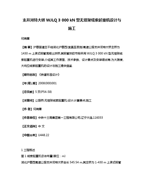
支井河特大桥WJLQ 3 000 kN型无塔架缆索起重机设计与施工何锦章【摘要】沪蓉国道主干线湖北沪蓉西(宜昌至恩施)高速公路支井河特大桥主桥为1430 m上承式钢管混凝土拱桥,其钢管拱肋节段采用WJLQ 3 000 kN型无塔架缆索起重机进行安装,介绍其工作原理、技术参数、设计要点及安装调试等,为大跨度、大吨位缆索起重机的设计与施工提供借鉴.【期刊名称】《铁道标准设计》【年(卷),期】2008(000)001【总页数】5页(P54-58)【关键词】公路桥;无塔架缆索起重机;设计;计算要点;施工【作者】何锦章【作者单位】中铁十三局集团第一工程有限公司,辽宁大连,116033【正文语种】中文【中图分类】U448.221 工程概述图1 缆索起重机总体布置(单位:m)湖北沪蓉西高速公路支井河特大桥全长545.54 m,其主桥为1-430 m上承式钢管混凝土拱桥,计算矢高为78.18 m,矢跨比为1/5.5。
主拱肋为钢管混凝土主弦杆和箱形钢腹杆组成的空间桁架结构,拱脚截面高度13 m,拱顶截面高度6.5 m,上下游两道拱肋平行布置,肋宽4 m,肋间距13 m,每道肋由上、下各2根φ1 200×35(30、24)mm的钢管弦杆组成,并通过上下横联、腹杆及横向斜杆组成空间稳定体系,肋间设20道“米”字撑横联。
因受到施工空间及运输条件的限制,拱肋共分成30个吊装节段和1节合龙段,吊装节段长度在26.226~14.046 m,设计合龙段长60 cm。
水平投影最长为21.639 m(第一节段),节段最大吊重达2 800 kN(双肋)。
节段间采用“先栓后焊、栓焊结合”的连接方式。
本桥主拱肋安装利用缆索起重机,采用“两岸对称悬拼、齐头并进至跨中合龙的斜拉扣挂法”施工。
整个吊装系统由缆索起重机系统和斜拉扣挂系统组成。
2 WJLQ3 000 kN型无塔架缆索起重机2.1 概况缆索起重机设计跨径756 m,单钩起吊能力750 kN,额定起重量为4×750=3 000 kN。
沪蓉西高速公路

• • •
(二)特长隧道
• 由于地形复杂,导致沪蓉西项目隧道众多,宜恩段初步设计共设隧道 26座,长度占路线的比例达到27.6%。本项目超过3公里的特长隧道 共计8座,其中具有代表性的有夹河岩隧道、龙潭隧道、野三关隧道。 夹活岩隧道。夹河岩隧道位于宜昌市长阳县,左洞长5146米,右洞 长5224米,穿越丹水支流沿溪与干沟之间的分水岭。 龙潭隧道。龙潭隧道进口位于宜昌市长阳县贺家坪镇堡镇村,出口 位于长阳县榔坪镇长丰村,左洞长8674米,右洞长8670米。 八字岭隧道。八安岭隧道位于恩施州巴东境内,左洞长3536米,右 洞全长3560米,隧道穿越丫叉河水系与四渡河水系之间的分水岭,最 大埋深390米。 野三关隧道。野三关隧道位于巴东野三关镇,左线长3677米,右线 长3650米,最大埋深240米。 张家冲隧道。位于巴东野三关镇境内,左线长3350米,右线长 3475米。 香炉山隧道。位于巴东县大支坪境风,左洞长3980米,右洞长 3960米。 大水井隧道。位于恩施市境内,左洞长3400米,右洞长3450米。
二、技术标准
• 沪蓉西高速公路全线采用技术标准为双向四车道山区高速 公路标准,各项设计技术指标如下: 设计行车速度: 80km/小时,山岭重丘区。 平纵指标:平曲线最小半径极限值 250米、一般值400 米,最大纵坡5%,凸曲线一般最小半径4500米,凹曲线 一般最小半径3000米,竖曲线最小长度70米,停车视距 110米。 路基宽度:整体式路基宽度为 24.5m,分离式路基宽 2×12.5米;中央分隔带宽1.5米。 荷载等级:汽车 -超20、挂车-120。 桥面布置:整体式与路基同宽 24.5米,中央分隔带1.5 米,分上、下行独立桥梁,外侧护拦0.5米,内侧护拦0.7 米;分离式桥梁宽度12.5米,内外侧护拦宽均为0.5米。 设计洪水频率:特大桥 1/300、大桥1/100。 通航标准:无通航要求。 隧 道:单洞建筑限界净宽为 0.75+0.25+0.5+7.5+0.5+0.25=9.75米,净高5米。 地 震:设计基本烈度6度,按7度采取抗震措施
支井河特大桥钢管主拱肋安装方案
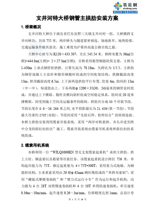
支井河特大桥钢管主拱肋安装方案1.桥梁概况支井河特大桥位于湖北省巴东县野三关镇支井河村一组,大桥横跨支井河峡谷,谷深755米,两岸桥头与隧道紧密相连,场地狭窄,地势险要,交通运输条件极其恶劣,施工难度为沪蓉西高速公路全线之最。
大桥中心桩号为K120+433.507,全长545.54米,桥跨布置为36m(引桥)+444.8m(主桥)+ 2×27.3m(引桥)。
引桥采用箱型钢筋砼简支梁,主桥为1-430m上承式钢管砼拱桥,计算矢高为78.18m,矢跨比为1/5.5。
主拱肋为钢管混凝土主弦杆和箱形钢腹杆组成的空间桁架结构,拱脚截面高度13m,拱顶截面高度6.5m,上下游两道拱肋平行布置,肋宽4m,肋间距13m (中-中),每道肋由上、下各两根φ1200×35(30、24)毫米的钢管弦杆组成,并通过上下横联、腹杆及横向斜杆组成空间稳定体系,肋间设20道米撑横联。
因受到施工空间及运输条件的限制,拱肋共分成30个吊装节段,节段长度在0.6~26.266米之间,水平投影最长为21.639(第一节段),节段最大吊重约270T(双肋)。
节段间采用“先栓后焊、栓焊结合”的原则连接。
本桥主拱肋安装利用缆索吊装系统,采用“两岸对称悬拼、齐头并进至跨中合龙的斜拉扣挂法”施工。
缆索吊装系统由缆索吊机系统和斜拉扣挂系统组成。
2.缆索吊机系统本桥利用一台“WJLQ3000KN型无支架缆索起重机”承担主拱肋、拱上立柱、钢盖梁以及箱梁等吊装任务。
该缆索起重机设计跨径756米,单钩起吊能力为75T,额定起重量为4×75T=300T;采用重力式地锚,为钢筋砼结构;主承重索采用由20根φ62mm钢丝绳组成的“单跨双索制”;采用“螺旋式摩擦卷扬机”和“增力式运行小车”作为运行和起升机构,动力源为4台28T双筒慢速卷扬机和4台10T单筒快速卷扬机;牵引速度0.36m~10m/min,起升速度0.26~3m/min,位移精度达到1mm;总设计寿命为12500小时,工作级别为A7级。
中国大跨度钢桥建设新进展

钢梁简述 双塔双索面钢箱梁 双箱 钢混凝土组合箱梁 双塔双索面钢桁架双层 3跨连续钢箱梁 3跨连续钢箱梁 双塔双索面 3跨连续混合加劲梁 三塔斜拉桥主桥 三跨组合梁
合龙时间
2007 2009
建设中 建设中
2005 2000 2008 2000
桥、跨度420m的菜园坝长江大桥相继通车, 这两座桥分别排在我国钢拱桥跨度的第3、4 位。而无山长江公路大桥、支井河大桥分别 列钢管混凝土桥跨度前两位。 铁路桥方面,主跨504m的武汉天兴洲大 桥2008年9月合龙,目前动车组已经可以通 行。天兴洲大桥为武汉到广州客运专线在武 汉跨越长江的双塔三索面钢桁梁公铁两用斜 拉桥, 4线铁路6车道公路,正桥全长4657 米。首次采用钢桁梁节段架设方法。这座桥 是目前世界上最大跨度的公铁两用斜拉桥。 钢桁拱桥南京大胜关桥钢梁正在架设, 2009年内合龙。该桥是京沪高速铁路和沪汉 蓉铁路的越长江通道,同时搭载双线地铁, 为六线铁路桥。主跨2.336m,建成后将是世界 上最大跨度铁路钢拱桥,这座桥拱肋部位轴 向最大压力达至tJ9300t,采用Q420型E级高强 度桥梁钢。 目前,我国还有多座大跨度桥梁正在建 设,如主跨730m上海长江大桥,主跨708m闵 浦大桥,建成以后,我国在世界斜拉桥跨度 前lO名中的桥梁,都将是2l世纪建造完成的 桥梁。体现了我国21世纪桥梁设计与建造技 术的巨大进步和经济实力的强大。
上大桥以日本为主,而且都是本四联络桥中 的桥梁。那个时期,土耳其和丹麦分别建造 了跨越博斯普鲁斯海峡和大贝尔特海峡桥。 我国内地20世纪90年代刚刚开始建造大跨度 钢桥。当时,完全由中国人自己设计制造的 接近千米的大跨度钢桥是长江三峡工程西陵 长江大桥(900m)。2ltlJ:纪,中国的经济持 续增长,经济实力不断增强。钢铁产量连续 多年排名世界第一,钢材的品种和质量完全 可以满足建造大跨度钢桥的需要。因此,21 世纪前9年,世界千米以上的桥梁都是在中 国建造。不但如此,我国的钢桥制造企业和 桥梁施工企业,还承建着多做国外大跨度钢 桥。比如,近期合龙的主跨434m的印尼泗马 大桥。 从钢梁结构形式看,20世纪30年代到 60年代,大跨度桥梁的主要结构形式是钢桁 梁。这主要是由于在计算机没有发展起来 的时代,桁架结构可以按照杆系单元,运用 经典力学对结构进行受力分析,受力非常明 确。桁梁在制造时,钢板首先下料、加工成 杆件,然后将杆件拼装成桥梁。这样的制造 和架设技术,以及广泛用于钢梁的铆接技术
湖北支井河大桥设计
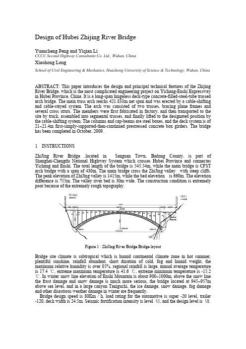
1 INSTRUCTIONSZhiJing River Bridge ,located in Sanguan Town, Badong County, is part of Shanghai-Chengdu National Highway System which crosses Hubei Province and connectes Yichang and Enshi. The total length of the bridge is 545.54m, while the main bridge is CFST arch bridge with a span of 430m. The main bridge cross the ZhiJing valley with steep cliffs. The peak elevation of ZhiJing valley is 1415m, while the bed elevation is 660m. The elevation difference is 755m. The valley river bed is 30m wide. The construction condition is extremely poor because of the extremely rough topography.Figure 1 : ZhiJing River Bridge Bridge layoutBridge site climate is subtropical which is humid continental climate zone in hot summer, plentiful sunshine, rainfall abundant, short duration of cold, fog and humid weight, the maximum relative humidity is over 85%, regional rainfall is large, annual average temperature is 17.4 ℃, extreme maximum temperature is 41.6 ℃, extreme minimum temperature is -15.2℃. In winter snow line elevation of Enshi Mountain is about 900~1000m, above the snow line the frost damage and snow damage is much more serious, the bridge located at 945~957m above sea level, and in a large canyon Taniguchi, the ice damage, snow damage, fog damage and other disastrous weather damage in winter are frequently.Bridge design speed is 80Km / h, load rating for the automotive is super -20 level, trailer -120, deck width is 24.5m. Seismic fortification intensity is level Ⅵ, and the design level is Ⅶ.Design of Hubei Zhijing River BridgeYuancheng Peng and Yiqian Li CCCC Second Highway Consultants Co. Ltd., Wuhan, ChinaXiaohong LongSchool of Civil Engineering & Mechanics, Huazhong University of Science & Technology, Wuhan, ChinaABSTRACT: This paper introduces the design and principal technical features of the Zhijing River Bridge, which is the most complicated engineering project on Yichang-Enshi Expressway in Hubei Province, China. It is a long-span hingeless deck-type concrete-filled-steel-tube trussed arch bridge. The main truss arch reachs 421.833m net span and was erected by a cable-shifting and cable-stayed system. The arch was consisted of two trusses, bracing plane frames and several cross struts. The members were first fabricated in factory, and then transported to the site by truck, assembled into segmental trusses, and finally lifted to the designated position by the cable-shifting system. The columns and cap-beams are steel boxes, and the deck system is of 21~21.4m first-simply-supported-then-continued prestressed concrete box girders. The bridge has been completed in October, 2009.168 ARCH’10 – 6th International Conference on Arch Bridges 2 THE MAIN BRIDGE STRUCTURE DESIGNIn the preliminary and technical design phase, two schenes were considered. One is a 450m concrete filled steel tubular (CFST) arch bridge, and the other is a 676m suspension bridge using tunnel anchor technology.According to geological surveys and research on tunnel anchor, the two sides are well developed in rock cracks unloading. The unloading relaxation width is large (approximately 45m) and there is 3 large fissures at Enshi shore. Therefore the tunnel-type anchor is difficult to set up, and the gravity anchorage also can not be adopted because of steep terrain of both shores.At last, the arch bridge is recommended to be adopted as the solution in this project. The situation of constructional impairment and the difficulties of construction were considered at the construction drawing design stage. The preliminary design of the 450-meter arch bridge’s abutment location and the span ratio has been adjusted based on the technical design, 430m main span of the arch program is adopted, so that No. L3 cracks of Enshi shore is avoided.The span of main arch is 430m, cross the bridge arch on a total of 21 holes, span of 19.1m +19 ×21.40m +19.1 m, Yichang shore Approach to 1-36.0m, Enshi shore Approach for 2-27.3m. Full-bridge is located -1.89% ~-2.09% one-way cross-slope and 2% Zongpo two-way cross-slope.2.1 The main arch ribs and arch seatThe span of arch rib is 430m, arrows high is 78.18m, span ratio is 1/5.5, is composed of concrete filled steel tubular main chords. The box-shaped steel belly bar space truss structure, the section height of rib vault reaches 6.5m, while arch foot reaches 13m; the spacing between two ribs is 13m (in the - middle), the horizontal width of rib is 4m. Every rib made from the upper and lower of two ф1200 × 35 (30,24) mm, within steel concrete which is filled with No.50 concrete, and through the upper and lower horizontal line, belly bar and horizontal space for stable system composed of diagonals. In the two arch ribs are located 20 meters horizontal stays horizontal line, are steel truss.Figure 2 : General tectonic layout of the main arch ribsThe transportation ability is limited because the bridge is located in complex terrain. The processing of large segments of the overall transport which produced in factory is difficulties. The small unit spare parts could be delivered to the site, while it is also difficult to guarantee on-site welding quality of the main force component. Therefore, rib components node board are used to connect high-strength bolts in the factory processing pre-fight, so the part of arch ribs are made of high-strength bolts connecting node board and the spare parts are delivered to the site, and assembled the resumption of large segments (by ventral pole to form a complete "N" division) in place of assembled platforms, the connection principle is "After the first bolt welding, bolt welding with", meaning tube end set blue plate, using high-strength bolt connection, pipe outer seam penetration welding a circuit. To facilitate the workers, in the main steel tube construction, stepping in the pipe welded reinforced underside are set.Yuancheng Peng, Yiqian Li and Xiaohong Long 169 The main arch rib installation are used of cable crane system, using "two sides symmetrical cantilever, in parallel to the cross in the closure of the cable-stayed hanging Law" construction. Cable crane hoisting system consists of cable and cable-stayed pegged system.The main arch seat using integrated reinforced concrete structure, abutment foundation should be placed in stable. The complete weak weathered bedrock, the required bearing capacity of foundation to allow no less than 2000KPa.2.2 Arch bridge on the column and system structureThe column upper arch using 1.4×1.0 steel box structure, factory sub-processing, on-site sub-hoisting welding. The cover also used steel box beam structure. The whole beam is made in a factory, transport to the site and hoisting to the location. To facilitate the conservation of columns and cap beams, a beam at one end to open a maintenance crossing is built, in the columns and cap beams converge at the capping beam to open a hole on the bottom, and the maintenance workers can easily enter the column inside, the column are equipped with steel escalator up to the bottom.Prestressed concrete are used in continuous box girder, full-bridge horizontal fabric eight small box-girder. The width of precast beam is 2.4m, sit wet joints between the main beam is 65cm. After the in-situ continuous lifting of precast concrete pier top will each piece main beam in the longitudinal bridge to connect, design strength of concrete up to be 90% of post-tensioned pier top steel beam to resist the negative moment. Finally the main beam in-situ joints between the wet concrete, one bridge deck can be formed.The box girder used A class of partially prestressed concrete structure. The middle pier top used double-row bearings, the negative moment area will be adopted the continuous prestressed reinforcement.In order to meet the requirements of anchor layout, the box girder ends was thickening.Figure 3 : General tectonic layout of the main arch ribs2.3 Structure of the junction of PierAbutment pier is located at the junction of the top surface, using double-column 5.0×3.5m. The thickness of wall is 40cm which composed of reinforced concrete thin-walled hollow piers. The junction of piers can be used as a tower platform to meet the requirements to withstand construction loads during the construction.2.4 Welding designThe arch truss, column, cover beams are made of steel, using factory-produced, site assemblage installation methods. According to the load needs and the site of the different environmental conditions, taking into account the relevant norms of the structure of various parts of the weld type and quality, the welding requirements as follows:Longitudinal welded seam and circumferential butt welding are made in factory. Using automatic protective welding process, full penetration type weld quality up to gradeⅠ.170 ARCH’10 – 6th International Conference on Arch Bridges Arch truss, column, cover etc. structural unit or a combination of beam welding, are full-penetration type weld quality achieved Ⅱ.The site installation of welding are basically operated at high altitude. Angle-weld type, U-type multi-layer welding can be non-penetration type weld, so the quality grade is Ⅲ, without flaw, but they must meet "quality standards for visual inspection welds. "3 MAJOR CONSTRUCTION PROGRAMThe cable crane without stents that is typed "WJLQ3000KN" is used to construct the main arch rib in this project. Columns on the arch, steel cap beams and box girders. With the design span of 756 meters, the single-hook lifting weight of 75T and rated total lifting weight of 4×75T=300T; using reinforced concrete gravity anchors during the construction; the main load-bearing cable is "single-Span and double-Cable style" which is combined by 20 ropes with the diameter of 62mm; "spiral friction hoist" and "car running by increasing force" are used as the running and lifting mechanism; the power is provided by four 28T binoculars slow hoists and four 10T monoculars fast hoists; traction speed is 0.36~10m/min, lifting speed is 0.26-3m~min, displacement accuracy is less than 1mm; total design life is 12,500 hours and the working-level is A7.According to the structure of the bridge and the feature of topographic, the cable-stayed hanging system of the main arch rib is a system of conversion and balance of force. It is composed by fulcrum that is the pier(capping beams) at the junction of shore and stiff load transfer beam that is anchor beam on top of pier and abutment. Through the buckle cable, balanced cable, pre-stressed anchor, approach bridge box girder. The cable-stayed hanging system is composed by five parts: buckle point, buckle cable, buckle pier and anchor beam, balance ropes and anchorages, bracing system of buckle pier and anchor beam.In order to reduce the adverse effect that caused by the excessive weld from traditional buckle point on the main structure, setting steel anchor beam under the winding pipe to connect the main arch rib and buckle cable at the buckle point. Steel anchor beam support the arch rib through node plate and make occasional connection between the battens of the arch rib node plate and the bolt.To avoid the local excessive stress, which may cause the bucking at the thin-walled steel pipe and the node plate, main chord steel and node plate at the buckle point of the main structure was partial to strengthen, added 1~4 stiffened plates with 16mm wide and 100mm thick. Added 50mm wide and 16mm thick stiffened ring in the main arch steel at the buckle points of L9、L10、Z4、Z5,which bear larger force. To the cable force is larger than 100t of the buckle cable(L9、L10、Z2、Z4、Z5), set reaction frames at each buckle point. There should be 40 reaction frames in this bridge. The structure type of the reaction frame is public-shaped block welded by plate, the height of the frame is 270mm and the contact surface with the node of arch rib and steel anchor beam is 500×680mm and 200×500mm. The effect of buckle cable is delivering the construction load such as the weight of arch rib during the construction of arch rib to the buckle pier and anchor beam and appropriately adjust the elevation of the main arch rib.Semi-cross-rib is divided into 15 segments to construct, each segment is located buckle cable, the 3rd,6th,9th,12th,15th segment number are followed Z1~Z5; the others are followed L1~L10. Each buckle cable has 4 beams, symmetrical arrangement in the medial or lateral rib. According to the different force in cable, buckle cable is strand, respective choice for the strand, 3φ15.24~18φ15.24.Buckle cable with single-end tension, the tension-side is at anchor beam of the junction pier, fixed end is in the buckle point of the arch rib.Z1 ~ Z5 buckle cable tension side is adjustable anchor named OVM25O, L1 ~ L10 buckle end of cable tension using OVM15 type of common anchor. "P"-type anchor are used in all the fixed end of prestressed steel beams.The cable stress in the L1~L4 is little, to make the force of structure clear and reused steel anchor beams, after the Z1, Z2 fastened, may remove L1 ~ L4 buckle cable, the remaining buckle cable will be removed after the closure of the main arch ribs.Yuancheng Peng, Yiqian Li and Xiaohong Long 171 Cable buckles are the horizontally symmetrical arranged inside the steel pipe of the arch ribs or outside, are away from all the transverse coupling components of the main arch. Angle of vertical buckle cable install: Yichang was 76.132 ° ~ 3.095 °, Enshi was 74.416 ° ~ 0.795 °Table 1 : One exampleBuckle cablenumberL1L2 Z1 L3L4Z2 L5L6Z3L7L8Z4 L9 L10 Z5 Maximum cable force 2125 66 4242105525063707495 110 123 171Yichangnφ15.24 3 3 7 4 410 5578810 12 14 18 Maximum cable force 2025 66 44441105555687681109 125 138 196Enshinφ15.24 3 3 7 4 410 5578810 12 14 184 THE MAIN TECHNICAL CHARACTERISTICS(1) This CSFT deck arch bridge is ranked as the longest one in the world with the main span of 430m;(2) This bridge, across the deep groove Canyon, links with tunnels on two end sides. It is necessary to excavate a small 800m long tunnel to reach the construction site at the Enshi shore. The complex topography and difficult transportation ranks it as the worst construction condition in the world;(3) The topography at two end sides are steep cliffs with no change to set the wind cables. Maximum cantilever length of the main arch cable-stayed hanging is 215m, seldom recorded; (4) The elements of the arch ribs are connected with node plates and high-strength bolts, which are first fabricated and processed in the factory, then delivered to the construction site, and finally assembled on the platform after hoisting of large segments in place, using the method of "bolting first, then welding”, or “combined bolting and welding .REFERENCESChen Baochun, 1997. A summarized Account of Developments in Concrete-filled steel tube arch bridge, Bridge construction, 2(2): p.8-13.Chen Baochun, 2003. State-of-art-theory of calculation for Concrete-filled steel tube arch bridge, China Civil Engineering Journal, 12(36): p.47-57.We Jiangang and Chen Baochun, 2004. Finite element methods for analysis on material nonlinearity of concrete-filled steel tubular arch, Journal of Fuzhou University(Natural Science), 6(32): p.344-348.Xu Yan and Hu Side, 2006. A study on the dynamic ultimate capacity of CFST arch bridge, China Civil Engineering Journal, 9(39): p.66-73.Hu Shide and Su Hong, 2004. Three dimensional elasto-plastic seismic response analysis of CFST bridge, China Journal of Highway and Transport, 1(1): p.57-61.。
预应力钢筋混凝土简支T型梁设计方案

前言公路桥梁交通是为国民经济、社会发展和人民生活服务的公共基础设施,是衡量一个国家经济实力和现代化水平的重要标志。
我国从“七五”开始,公路建设进入了高等级公路建设的新阶段,近几年随着公路等级的不断提高,路桥方面知识得到越来越多的应用,同时,各项规范也有了较大的变动,为掌握更多路桥方面知识,我选择了支井河大桥施工图设计这一课题。
本次设计路段位于巴东县野三关镇支井河村. 它是根据设计任务书的要求和《公路桥规》的规定,选定装配式预应力T形截面简支梁桥,该类型的梁桥具有受力均匀、稳定,且对于小跨径单跨不产生负弯矩,施工简单且进度迅速等优点。
设计内容包括拟定桥梁纵,横断面尺寸、上部结构计算,下部结构计算,施工组织管理与运营,施工图绘制,各结构配筋计算,书写计算说明书、编制设计文件这几项任务。
在设计中,桥梁上部结构的计算着重分析了桥梁在施工及使用过程中恒载以及活载的作用力,采用整体的自重荷载集度进行恒载内力的计算。
按照新规范公路I级车道荷载进行布置活载,并进行了梁的配筋计算,估算了钢绞线的各种预应力损失,并进行预应力阶段和使用阶段主梁截面的强度,正应力及主应力的验算。
下部结构采用以钻孔灌注桩为基础的墩柱,并分别对桥墩和桩基础进行了计算和验算。
主要依据《公路钢筋混凝土及预应力混凝土桥涵设计规范》(JTG D062-2004),《公路桥涵地基与基础设计规范》(JTJ 024-85、,《公路钢筋混凝土及预应力混凝土桥涵设计规范》(简称《预规》)JTG D60—2004《公路桥涵设计通用规范》(简称《通用规范》)在本次设计过程中,新旧规范的交替,电脑制图的操作,都使我的设计工作一度陷入僵局。
在指导老师***老师及本组其他组员的帮助下,才使的这次设计得以顺利完成。
在此,对老师和同学们表示衷心的感谢。
由于公路桥梁工程技术的不断进步,技术标准的不断更新,加之本人能力所限,设计过程中的错误和不足再所难免,敬请各位老师给予批评指正。
钢管混凝土拱桥桥例简介_下_
中 外
公
路
139
钢管混凝土拱桥桥例简介( 下)
陈宝春
( 福州大学 , 福建 福州 摘 350108)
要 : 该文简 要介绍了部分 2000 年以来修建的以及目前在建和正 在设计中 跨径较大
#
钢管拱肋安装采用缆索吊机斜拉悬臂拼装法, 吊 塔和扣塔分离。全桥共分 39 节段吊装 ( 其中拱肋 26 段, 横撑 11 段, 拱上横梁 2 段 ) 。大桥建成后的照片见 图 7。
图 7 三门跨海大桥北门桥 建成后照片 ( 田仲初提供 )
5
湖南湘西王村特大桥
王村特大桥为张家界至罗依溪公路上的一座中承
图2
浙江淳安南浦大桥总体布置图 ( 单位 : m)
内及个别腹杆内所灌的 C50 混凝土 , 采用能补偿收缩 值的微膨胀混凝土。 两拱肋中距 18. 6 m 。全桥桥面以上设 6 道钢管 桁架横撑 , 桥面以下设 2 道横撑 , 其主管为 720 mm ! 12 mm 。弦杆、 腹杆及横撑钢管均采用 Q345c 钢卷制 的螺旋焊接管。 吊杆采用 55 7 mm ( 61 7 mm ) 镀锌高强平行钢丝 束, 两端采用 OVML ZM - 55( OVML ZM - 61) 冷铸镦 头锚, 上下两端锚具设有可调节横梁高度的螺母。吊
图 8 湖南湘西王村特大桥建 成后照片
图 6 三门跨海大桥北门桥总体布置图 ( 单位 : cm)
142
中
外
公
路
28 卷
成后的照片见图 9。
6
武汉晴川大桥( 汉江三桥)
武汉晴川大桥( 汉江三桥 ) 的设计荷载为 : 汽车 -
文秘写作 工程施工新闻报道

工程施工新闻报道工程施工新闻报道现场施工报道时光匆匆,就这般不留一丝痕迹地前行着,将其足迹深深地刻划在时空的隧道里。
当人们还沉浸在那秋天的夕阳之中,初冬已悄然来到。
然而在xx建设现场,却是犹如初夏,热火朝天,忙碌万分。
在这寒风阵阵,万物沉寂的季节里,大家不畏寒冷,干劲十足,舍我其谁,势必要干出点样子,干出我建工博海敢于亮剑、勇往直前的精神。
大家深知工期紧,任务重,又加上冬季施工困难重重,但是为了确保按期保质保量完成今年施工建设任务,全体工作人员忘我工作,加班加点,相互鼓舞,勇于抽出宝剑,亮剑拼搏,努力打好今年的最后一仗,为明年打一个好的开端,为让施工班组顺利快速的进行施工,项目部各科室为其提供了坚强有力的保障,在施工过程中,项目部各科室努力干好本职工作,同时又相互协调作战,共同保证工程项目紧张有序进行。
冰未消,雪未融,施工现场仍是如火如荼,钢筋工,木工,管理人员,各司其职,坚守现场,为了一个共同的目标的而无私的奋斗着,一段钢筋,模板,混凝土,二段钢筋,模板,混凝土,三段,。
严格按照施工进度计划采用流水施工作业,呼市的深夜,白天热闹的街道在冬天寒冷的夜幕下似乎被冰冻了,只有瑟瑟寒风和轰隆的机械,为偶尔经过的行人唱着夜曲.为了保证夜间浇筑混凝土的质量,避免混凝土的浪费,我项目经理部,设置三个打灰小组,轮流夜间指第二篇、施工工程通过验收新闻稿工程施工新闻报道施工工程顺利通过验收新闻稿xx年1月13日,使用方、施工方、监理方、审计方等部门组成的小组集中验收了修购专项资金支持的房屋修缮和基础设施改造等20余个项目。
今年暑期修缮项目重点集中在修缮、水电暖基础设施改造等。
针对暑期改造项目时间紧,任务重的特点,按照“抓质量、促工期、控成本、保安全”的总体要求,相关单位一起,积极推进,确保各项工程按时间结点保质保量完成。
针对卫生间异味大、楼宇条件设施陈旧、办公面积不足等问题,改造工程充分听取了使用部门的意见和建议,相关部门组织论证、精心设计、有效实施,发挥相关专业优势,聘请专业人员指导改造工作,坚持“样板”引路原则,确保施工质量和效果。
施工日志及大事记

施工日志天气:平均温度:。
C 日期:年月日工程名称工程部位施工单位中铁十四局集团有限公司施工负责人1、工程进度及上级有关指示:2、施工方法及施工组织:3、投入主要人力及机械设备:4、使用主要材料的规格、数量及试验结果:5、完成主要工程数量及质量情况:6、设计变更情况、检查发现问题及解决办法:7、现场管理情况:(技术人员、安全、文明施工、环水保等)填写人:2002年12月27日,湖北沪蓉西高速公路工程项目部(筹备组)经鄂交人劳[2002]697号文成立2003年1月16日,湖北省山区高速公路技术专家顾问组经鄂交基[2003]20号文成立5月23日,省政府办公厅以鄂政办函[2003]48号文成立湖北沪蓉西高速公路建设指挥部12月5日,国家发改委以发改交运[2003]2119号文正式批复上海至成都国道主干线湖北宜昌至恩施公路工可立项2004年6月3日,交通部以交公路发[2004]271号文件正式批复上海至成都国道主干线湖北宜昌至恩施公路初步设计6月24日,交通部西部交通建设科技项目管理中心支持通过了《沪蓉国道主干线龙潭特长隧道特殊地质条件下的关键技术研究》等3个科研课题的可研评审8月17日,省编委以鄂编函[2004]77号文批复设立湖北省沪蓉西高速公路建设管理处8月20日,湖北沪蓉西高速公路宜恩段开工典礼9月9—11日,交通部专家组对部勘察设计示范工程沪蓉西恩利段初步设计进行现场审查咨询10月23日,野三关隧道右线出口发生坍方,同时左侧上边坡开裂,引起有关各方高度重视2005年1月13日,花石板1#大桥桥址处发现巨型溶洞1月24—25日,省指召开魏家洲特大桥岸坡稳定性及处治方案听证会2月6日,湖北沪蓉西高速公路总监理工程师办公室经鄂交人劳[2005]55号文批准成立2月16日,支井河特大桥宜昌岸拱座开始开挖4月26日,野三关隧道意外坍塌,因施救及时,正在洞内作业的27名工人成功脱困4月30日,曹传林赴京参加“2005年全国劳动模范和先进工作者表彰大会”5月9日,中央政治局委员、时任湖北省委书记俞正声视察大水井隧道5月9日,支井河特大桥恩施岸施工横洞贯通7月5日,交通部以交公路发[2005]301号文批复沪蓉国道主干线湖北恩施至利川公路初步设计文件7月31日,省指召开真空灌浆工艺现场会和大体混泥土施工技术讲座8月24日,“水南特大桥8号墩深孔桩基施工技术方案与施工安全专项方案”评审会在野三关举行9月9至10日,省指召开隧道TSP超前地质预报技术研讨会9月20日,大水井隧道右线贯通11月30—12月1日,时任交通部总工程师冯懋润、交通部质监总站站长李彦武等视察了沪蓉西高速公路11月30日,交通部副部长冯正霖视察沪蓉西高速公路宜长段12月21日,省委书记、时任湖北省省长罗清泉视察沪蓉西高速公路宜长段12月27日下午,中央政治局委员、时任湖北省委书记俞正声视察沪蓉西工程12月30日上午8:00,沪蓉西高速公路宜长段通车试运营2006年3月9日,八字岭隧道右线贯通3月25日,大水井隧道左线贯通。
桥梁结构实时监测
二、桥梁结构健康监测
1、桥梁实时监测
一般来说针对、特大特殊结构桥梁,需要建立桥梁健康 监测系统,对大桥进行实时监测。
二、桥梁结构健康监测
传感器系统(SS)
传感器系统
数据采集单元
结
数据采集与传输系统(DATS)
构
数据传输网络
健
康
数据处理与控制服务器
监 测
数据处理与控制系统(DPCS)
系
相应的软件系统
(1)数据预处理 数据采集系统中的原始监测数据的预处理是各子系统采
集仪上完成,预处理后的数据经桥头交换机通过光纤传回监 控中心,监控中心的工控机接收预处理后的数据并实时显示。 工程单位转换:该变换可以分为线性参数的变换和非线性 的变换。对于线性输出的传感器,应分别对每支传感器的满 度系数和零点进行修正。对于非线性输出的传感器,还要进 行非线性修正。另外有些传感器还需要进行温度补偿。
实时监测工程实例实时监测工程实例数据采集单元1dau1传感器端数据采集单元2动态称重系统传感器端通用采光纤光栅解调仪gps接收机通用采wim数据采集光纤收发器桥址交换光纤收发器光纤传感器电类传感器电类传感器gps天线光纤收发器光纤收发器光纤收发器光纤收发器光纤收发器压力环116视频切换器大屏幕通用传感器工控机gps工控机光纤传感器工控机结构健康评估工作站动态称重系统工控机数据库系统服务器视频分配器视频分配器视频分配器视频分配器视频分配器视频分配器磁盘阵列光纤收发器监控中心监控中心以太网交换机路由器isp提供商实时监测工程实例支井河大桥主跨430米铁罗坪大桥跨径702米四渡河大桥主跨900米龙潭河大桥1063200106米实时监测工程实例实时监测工程实例恩施监控中心高速公路通讯光缆施家梁子边坡安全监测系统其他6座连续刚构桥梁定期监测系统湖北沪蓉西高速公路集群式结构健康监测系统2桥梁定期监测针对大中桥梁从节约系统投资成本的角度对桥梁实施定期监测
支井河特大桥实施性施工组织设计分析
第一章总则一、编制说明湖北沪蓉国道主干线是我国公路主骨架网“五纵七横”中的“一横”,湖北省宜昌至恩施高速公路是其重要的组成部分,是鄂西南地区必不可少的重要运输通道。
沪蓉西21合同段工程是该项目中施工条件最恶劣、施工难度最大的工程之一,其中支井河特大桥地处陡深河谷,交通极不便利,而且主桥采用钢管砼拱桥,施工工艺复杂,施工精度要求极高。
为了保证本工程优质、按期完工,特编制此《支井河特大桥实施性施工组织设计》(以下简称《施组》),做为施工中的指导性方案。
二、编制依据(一)沪蓉西高速公路第21合同段工程施工招标文件、设计图纸。
(二)我单位组织技术人员对施工现场及周边环境进行踏勘和调查后取得的详尽资料。
(三)中华人民共和国交通部现行公路设计规范、施工规范、施工技术规程、质量评定标准与验收办法。
(四)省、市人民政府及有关部门在施工安全、环境保护及当地资源管理方面的规定与要求。
(五)业主及监督、监理单位针对本工程提出的具体的要求与标准。
(六)我单位拥有的同类工程的施工经验、设备配置、技术储备和施工能力。
三、编制原则本《施组》主要遵循保证安全、保证质量、保证工期、控制污染、节约资源的原则进行编制,各项措施和标准的制定均以这五项原则为基本出发点。
第二章工程概况支井河特大桥位于巴东县野三关镇支井河村一组,沪蓉国道主干线湖北省宜昌至恩施高速公路榔坪~高坪段,宜昌侧(东侧)接漆树槽隧道出口,恩施侧(西侧)接庙垭隧道进口,由于桥隧紧密相连,两侧均为陡峻的悬崖峭壁,交通运输条件之恶劣、施工场地之狭小、工程之艰巨为全路段之最。
一、结构型式支井河特大桥中心桩号为K120+433.507,起点桩号为K120+170.037,终点桩号为K120+715.577,桥梁全长545.54米,主桥为上承式钢管砼拱桥,引桥为简支梁桥,桥跨布置为1*36m(引桥)+1*19.1m+19*21.4m+1*19.1m(主桥)+2*27.3m(引桥)。