SD8925G 输入10V-30V输出5V 2.1A同步降压车充IC
力驰微电子科技 LC9201D 锂电池充放电管理芯片说明书
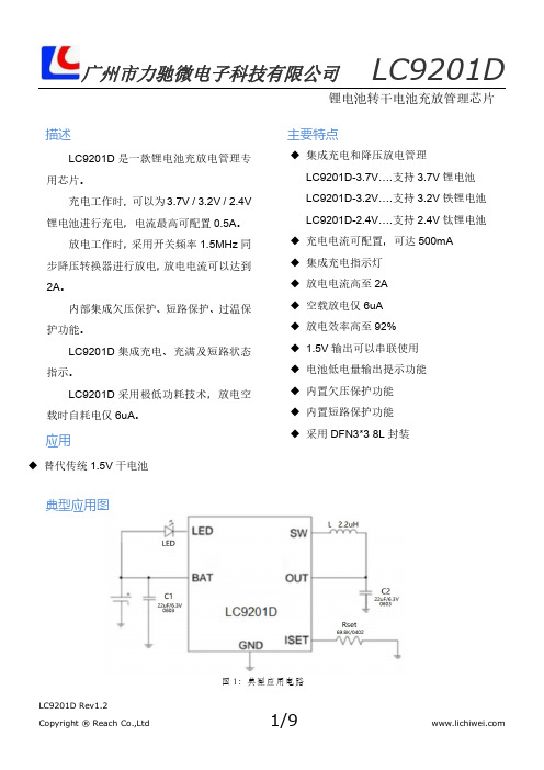
描述LC9201D是一款锂电池充放电管理专用芯片。
充电工作时,可以为3.7V/3.2V/2.4V 锂电池进行充电,电流最高可配置0.5A。
放电工作时,采用开关频率1.5MHz同步降压转换器进行放电,放电电流可以达到2A。
内部集成欠压保护、短路保护、过温保护功能。
LC9201D集成充电、充满及短路状态指示。
LC9201D采用极低功耗技术,放电空载时自耗电仅6uA。
◆集成充电和降压放电管理LC9201D-3.7V….支持3.7V锂电池LC9201D-3.2V….支持3.2V铁锂电池LC9201D-2.4V….支持2.4V钛锂电池◆充电电流可配置,可达500mA◆集成充电指示灯◆放电电流高至2A◆空载放电仅6uA◆放电效率高至92%◆1.5V输出可以串联使用◆电池低电量输出提示功能◆内置欠压保护功能◆内置短路保护功能◆采用DFN3*38L封装◆替代传统1.5V干电池典型应用图主要特点应用锂电池转干电池充放管理芯片图1:典型应用电路Pin 序号Pin 定义说明1I SET 充电电流设置端2BAT 充电电流输出端3LED 充电状态指示端4GND 地5NC 悬空6SW 功率开关管输出,连接电感7NC 悬空8V AP /OUT适配器电压输入/1.5V 电池输出管脚说明管脚示意图极限参数(最大极限值是指超出该工作范围芯片可能会损坏)符号参数最小值最大值单位V PIN 管脚极限电压-0.37V T OP 工作温度-4085℃T STG 储存温度-65150℃ESD人体模式(HBM )2000V 机械模式(MM )200V注:为了增强散热能力,建议5脚6脚连接,7脚8脚连接,EP 与GND 连接。
参数符号测试条件最小典型最大单位充电适配器输入电压V AP 4.7 5.2 5.7V OVP R SET=69.8K 6.57.0V恒压浮充电压V CV 3.7V,充电电流降为I CHG/10时 4.15 4.20 4.25V 3.2V,充电电流降为I CHG/10时 3.66 3.70 3.74V 2.4V,充电电流降为I CHG/10时 2.77 2.80 2.83VRecharge电压V RCHG 3.7V锂电池 3.99 4.03 4.073.2V铁锂电池 3.51 3.55 3.59V 2.4V钛锂电池 2.63 2.65 2.68V充电电流I CHG R SET=69.8K450500550mA 涓流充电电流I TRIKL V BAT<V TRIKL,R SET=69.8K405060mA涓流充电阈值电压V TRIKL R SET=69.8K,V BAT上升,3.7V 2.6 2.7 2.8V R SET=69.8K,V BAT上升,3.2V 2.3 2.4 2.5V R SET=69.8K,V BAT上升,2.4V 1.7 1.8 1.9V涓流充电迟滞电压V TRHYS R SET=69.8K,3.7V150200250mV R SET=69.8K,3.2V100130160mV R SET=69.8K,2.4V80100120mVV CC-V BAT阈值电压V ASD V CC上升60100140mV V CC下降60100140mVISET引脚电压V SET R SET=69.8K充电时0.95 1.0 1.05V 充电过温保护阈值T OTP1温度上升此温度开始降低电流130℃放电电池端工作电流I Q Buck模式(空载)610uA I SD UVLO(关断模式)23uA输出电压V OUT BUCK模式 1.48 1.55V 开关频率f SW500mA负载 1.5MHz 低电量提示输出电压V OUT BUCK模式 1.05 1.1 1.15V电池低电量提示电压V BAT_LOW 3.7V锂电池 3.10 3.20 3.30V 3.2V铁锂电池 2.40 2.45 2.50V 2.4V钛锂电池 1.75 1.85 1.95V低电量提示输入电压迟滞V BAT_LOWHYS 3.7V锂电池150250mV 3.2V铁锂电池100150mV 2.4V钛锂电池60100mV欠压保护UVLO 3.7V锂电池 2.70 2.75 2.8V 3.2V铁锂电池 2.05 2.10 2.15V 2.4V钛锂电池 1.65 1.72 1.80V电气工作参数(无特殊说明,V IN=5V,Ta=25℃)功能框图图2:功能框图参数符号测试条件最小典型最大单位欠压保护滞回UVLO_hys3.7V 锂电池200250300mV 3.2V 铁锂电池140170200mV 2.4V 钛锂电池120150180mV 带载能力Iout2.0A 逐周期峰值限流I LIMT1正常工作状态 3.0A 逐周期峰值限流I LIMT2V OUT <0.4V2.0A 过温保护阈值T OTP2温度上升到停止工作150℃过温保护迟滞T OTP-HYS2温度下降到重启工作20℃LED 电流LED456mA电气工作参数(续)(无特殊说明,V IN =5V ,Ta=25℃)典型性能特征(除特别说明外,VIN=5V,V BAT=3.6V,L1=2.2µH,C B=22µF,C L=22µF)Iout=0.5A Iout=2A涓流充电恒流充电应用介绍工作模式判定LC9201D根据OUT引脚的电压V OUT和BAT引脚的电压V BAT进行比较,来判断其工作模式。
XD208H 200V车载电源IC 车载降压芯片 汽车高压供电芯片
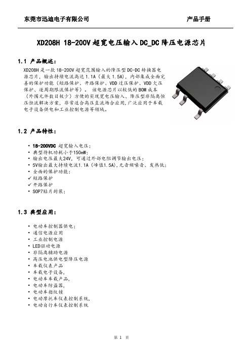
XD208H 18-200V 超宽电压输入DC_DC 降压电源芯片1.1产品概述:1.2产品特性:•18-200VDC 超宽输入电压;•典型待机功耗小于150mW;•输出电压最大24V,可通过外部电阻调节输出电压;•5V输出最大持续电流1.1A(峰值1.5A),无音频噪音、发热低;•全面的保护功能:✓短路保护✓开路保护•SOP7贴片封装;1.3典型应用:•电动车控制器供电;•通信电源应用•工业控制电源•LED驱动电源•非隔离辅助电源•高压电池供电型降压电源•车载仪表产品•车载电子设备,•电动车车载产品,•电动车防盗器,•电动车指纹锁•电动摩托车仪表控制系统,•电动自行车仪表控制系统XD208H 是一款18-200V 超宽范围输入的降压型DC-DC 转换器电源芯片,输出持续电流高达1.1A(最大1.5A),内部集成全面完善的保护功能(短路保护、开路保护、VDD 过压保护、VDD 欠压保护、逐周期限流保护等)。
该电源芯片以较低的BOM 成本(外围元件数目极少)方便的实现宽电压输入、降压型非隔离恒压恒流解决方案,非常适合高压直流场合应用,广泛应用于车载电子设备供电和工业控制电源等领域。
描述1.6功能框图:1.7典型应用电路1)典型应用电路之一(输出电压:5Vdc):2)典型应用电路之二(输出电压:12Vdc):【提示】1.输出电压计算:VOUT=2*(1+R3/R5)-1.2(内部VF常数);2.C2建议采用低ESR电容3.上述电路中的元件型号及参数值仅供参考,详情请咨询公司技术支持。
(备注1)1.9推荐的工作条件(备注2):参数数值单位工作环境温度-40to125°C1.10电气特性:除非特别注明,环境温度TA=+25℃。
参数名称符号测试条件最小典型最大单位电源电压部分VCC脚启动电流Ivcc_st 3.015uA工作电流Vcc_op V(FB)=3V,GATE=0.5nf1.0 1.5mA Vcc=20V待机电流Ivcc_standby0.5 1.5mA 退出VCC欠压锁定电压Vcc_on151617.5V 进入VCC欠压锁定电压Vcc_off8.09.010V 误差放大器部分内部误差放大器参考电压Vfb_ref 1.97 2.0 2.03V 电流检测输入部分限流阈值Vcs(max)490500510mV 功率MOS管备注1:超过这些额定值可能损坏器件,超出列表中”极限参数”可能会对器件造成永久性损坏。
车充 80V降压恒压方案 电动车5V手机充电USB接口

0HV
ORDERING INFORMATION
ABSOLUTE MAXIMUM RATINGS (1) Supply Voltage VIN ..................................................................................................... 80V VSW.....................................................................................................-0.3V to VIN + 0.3 V VBST ..........................................................................................................................VSW + 6.0V VISN, vISP ......................................................................................................................0V to15V All Other Pins ......................................................... -0.3V to +6.5 V -40C to 85 C SOP8 Junction Temperature.............................................................. 150° C Lead Temperature.................................................................... 260° C Storage Temperature ........................................-65° C to +150° C Recommended Operating Conditions (2) Supply Voltage VIN............................................................................+8V to 80V Output Voltage VOUT 0.8V to 30V Output Voltage VOUT (VIN<=16.5V)......... .0.8V to (VIN-3.0)V Operating Temperature........................................-40° C to +85 ° C Thermal Resistance (3) θJA θJC SOIC8................................. ....50 ........... 10 ... ° C/W
三节串联锂电池充电芯片5V和18V输入方案
三节串联锂电池充电芯片5V和18V输入方案
1.电源管理芯片:电源管理芯片负责将输入电压调整为合适的充电电压。
对于5V输入方案,可以使用DC-DC升压芯片将5V升压至锂电池的充电电压(通常为3.7V或4.2V)。
对于18V输入方案,可以使用DC-DC降压芯片将18V降压至锂电池的充电电压。
电源管理芯片一般还具备过压、欠压保护功能,保证输入电压在安全范围内。
2.电流控制芯片:电流控制芯片负责控制充电电流的大小。
在充电过程中,电流控制芯片会根据锂电池的状态和充电需求来调整充电电流。
一般来说,充电电流需要逐渐减小,直至充电完成。
电流控制芯片还可以通过PWM(脉冲宽度调制)技术调整充电电流的精度,保证充电电流的稳定性和准确性。
3.保护芯片:保护芯片主要负责监测充电和放电过程中的电压、电流和温度,以避免锂电池的过充、过放、过流和过温等问题。
当出现异常情况时,保护芯片会切断电池组与充电器或负载的连接,以保护锂电池的安全性。
此外,保护芯片还可以实现短路保护功能,防止短路情况下的电池过热和破裂。
总之,三节串联锂电池充电芯片是一种用于充电三节锂电池组的电路方案,通过电源管理芯片、电流控制芯片和保护芯片的配合工作,可以实现对锂电池的充电和保护功能。
在设计和制造中,需要考虑充电电压和充电电流的控制,以及对异常情况的保护措施。
屹晶 EG6599+EG4328 LLC 半桥谐振电源方案说明书 -- 60V12A 铅酸电池充电器

版本变更记录目录1 方案特性 (1)2 应用领域 (1)3 效率测试 (2)3.1 输入DC (2)3.1.1 效率曲线 (2)3.1.2 最高效率点现场图 (2)3.2 输入AC220V (3)3.2.1 效率曲线 (3)3.2.2 最高效率点现场图 (3)4 方案图片 (4)4.1 PCBA图 (4)5 LLC半桥谐振拓扑原理说明 (4)6 方案原理图及工作原理描述 (5)6.1 LLC频率设置 (6)6.2 恒压输出设置 (6)6.3 浮充电压设置 (6)6.4 输出电流设置 (6)6.5 转灯和风扇开启电流设置 (6)7 方案PCB (7)7.1 元器件位图以及走线图 (7)7.1.1 底板 (7)7.1.2 辅助电源 (7)8 方案板元器件列表 (8)8.1 BOM表 (8)8.2 关键元器件选型 (10)8.2.1 开关MOS管 (10)8.2.2 变压器 (10)60V12A铅酸电池充电器方案说明书1 方案特性⏹前级采用高压谐振变换器控制芯片EG6599⏹后级采用可编程电源管理芯片EG4328⏹输入电压范围:AC 220±10%⏹恒流输出:12.0A±1A (可定制)⏹恒压输出:DC73.5V±0.2V (可定制)⏹浮充电压:DC68.8V±0.2V(可定制)⏹转灯电流:2A±0.1A (可定制)⏹智能化充电管理,多重定时控制,可以防止电池过充⏹充电智能温度控制,高温充电功率智能下降,更好的保护充电器⏹可定制为锂电池充电器⏹输出短路保护反接保护⏹LED充电指示灯、12V风扇接口⏹PCBA尺寸:L163.5mm × W105.5mm× H55mm2 应用领域⏹电动三轮车充电器⏹电动四轮车充电器3 效率测试3.1 输入DC3.1.1 效率曲线备注:输入DC电压接输入电解电容两端。
3.1.2 最高效率点现场图输入功率输出功率效率图3-1 负载8A效率现场图注:效率=输出功率/输入功率。
便携音响充电管理芯片CPH8H0V.1故障检修
I我笔黎1C维修便携音响充电管理芯片CPH8H0V.1故障检修一台便携音响,在用外接U S B电源充电时,充电指示灯不亮,充不进电。
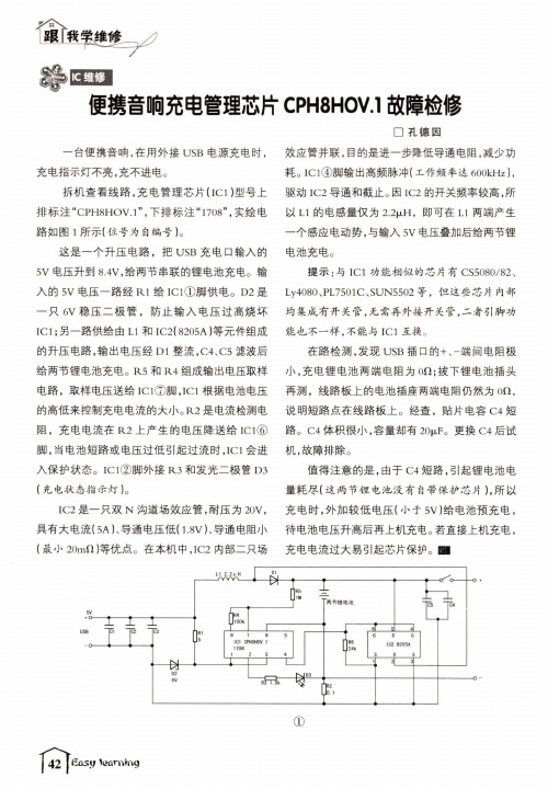
拆机查看线路,充电管理芯片(IC1)型号上 排标注“CPH8H O V.1”,下排标注“1708”,实绘电 路如图1所示(位号为自编号)。
这是一个升压电路,把U S B充电口输入的 5V电压升到8.4V,给两节串联的锂电池充电。
输 入的5V电压一路经R1给IC1①脚供电。
D2是 一只6V稳压二极管,防止输入电压过高烧坏IC1;另一路供给由L1和I C2( 8205A)等元件组成 的升压电路,输出电压经D1整流,C4、C5滤波后 给两节锂电池充电。
R5和R4组成输出电压取样 电路,取样电压送给IC1⑦脚,IC1根据电池电压 的高低来控制充电电流的大小。
R2是电流检测电 阻,充电电流在R2上产生的电压降送给I C1⑥ 脚,当电池短路或电压过低引起过流时,IC1会进 入保护状态。
IC1②脚外接R3和发光二极管D3 (充电状态指示灯)。
I C2是一只双N沟道场效应管,耐压为20V,具有大电流(5A)、导通电压低(1.8V)、导通电阻小 (最小20mfl)等优点。
在本机中,I C2内部二只场□孔德因效应管并联,目的是进一步降低导通电阻,减少功 耗。
IC1④脚输出高频脉冲(工作频率达600kHz},驱动I C2导通和截止。
因I C2的开关频率较高,所 以L1的电感量仅为2.2^H,即可在L1两端产生 一个感应电动势,与输入5V电压叠加后给两节锂 电池充电。
提示:与IC1功能相似的芯片有CS5080/82、L y4080、PL7501C、SUN5502等,但这些芯片内部 均集成有开关管,无需再外接开关管,二者引脚功 能也不一样,不能与IC1互换。
在路检测,发现U SB插口的+、-端间电阻极 小,充电锂电池两端电阻为O i l;拔下锂电池插头 再测,线路板上的电池插座两端电阻仍然为o n,说明短路点在线路板上。
12V转5V,20V转5V降压芯片和很低功耗LDO

12V转5V,20V转5V的降压电源芯片和很低功耗LDO前述:12V供电电压输入和20V供电电压输入转5V输出,恒压稳定输出5V这个是比较简单的,合适的芯片也是选择很多。
12V输入和20V输入两个电压相差有点多,所以在芯片选择时,也会有所以不同。
12V输入转5V版本:1,低功耗LDO电路:适应于12V输入和20V输入PW6206产品,是一颗输入3V-40V的宽输入电压线性LDO芯片,功耗4uA左右。
输出电压版本:3V,3.3V,5V。
2,大电流DC-DC降压电路:PW2162,输入4.5V-16V,输出电流最大2A,可调输出电压;PW2163,输入4.5V-16V,输出电流最大3A,可调输出电压;PIN to PIN PW2162 PW2205,输入4.5V-30V,输出电流最大5A,可调输出电压;PW2330,输入4.5V-30V,输出电流最大3A,可调输出电压;PIN to PIN PW2205 PW2312,输入4.5V-30V,输出电流最大1.2A,可调输出电压;PIN to PIN PW2162DC-DC 降压产品 输入电压 输出电压 输出电流 频率 封装 PW2057 2.0V ~6.0V 3.3V,1.8V,1.2V 0.7A 1.5MHz SOT23-5 PW2058 2.0V ~6.0V 1V ~5V 0.8A 1.5MHz SOT23-5 PW2051 2.5V ~5.5V 1V ~5V 1.5A 1.5MHz SOT23-5 PW2052 2.5V ~5.5V 1V ~5V 2.0A 1.0 MHz SOT23-5 PW2053 2.5V ~5.5V 1V ~5V 3.0A 1.0 MHz SOT23-5 PW2162 4.5V ~16V 1V ~15V 2A 600KHZ SOT23-6 PW2163 4.5V ~16V 1V ~15V 3A 600KHZ SOT23-6 PW2205 4.5V ~30V 1V ~28V 5A 500KHZ SOP8-EP PW2312 4.0V ~30V 1V ~28V 1.2A 1.4 MHz SOT23-6 PW2330 4.5V ~30V 1V ~28V 3A 500KHz SOP8-EP PW2431 4.5V ~40V 1V ~30V 3A 340KHz SOP8-EP PW2558 4.5V ~55V 1.25V ~30V 0.8A 1.2 MHz SOT23-6 PW2608 5.5V ~60V 1.5-30V 0.8A 0.3-1Mhz SOP8-EP PW2815 4.5V ~80V 1.5V ~30V 1.5A 400KHZ SOP8-EP PW2906 12V ~90V 1.25V ~20V 0.6A 150KHZ SOP8-EPPW2902 8V~90V 5V~30V 2A 140KHZ SOP8-EP PW2153 8V~140V 5V~30V 4A 140KHZ SOP8。
NS2582同步升压双节锂电池充电管理IC说明书

NS2582同步升压双节锂电池充电管理IC1特性●最大2A 输出同步开关型升压充电器●升压效率可高达90%以上●内置电池短路/涓流/恒流/恒压模式●±0.5%电池恒压模式电压精度●支持LED 充电状态指示●支持充电电流外部可调●支持输入适配器DPM 功能●外置EN 使能关闭功能●电池恒压模式电压8.4V 和8.7V 可选●热调节和OTP 温度保护功能●输入电压UVLO 和OVP 保护功能●输出过压和短路保护●开关频率:1.2MHz ,可支持1uH 电感●内置NTC 电池温度检测和使能功能●支持无电池模式下升压功能正常工作●ESSOP-10和ETSSOP-14L 封装2应用范围●蓝牙锂电池应用●电子烟●便携式锂电池笔记本●锂电池手机,PDA ,MP3和PM4播放器●PSP 和NDS 便携式游戏机等3说明NS2582是一款支持4-5.5V 输入电压范围,最大输出为2A 电流的同步升压双节锂电池充电管理芯片。
芯片内部集成了极低导通电阻的MOSFETS ,以实现较高的充电效率,芯片只需要极少数的外围器件。
NS2582工作频率为1.2MHz ,内部集成了多重保护功能,能够最大程度的保护芯片和终端设备。
可通过调节RICHG 电阻的阻值改变CC 模式下的充电电流大小,通过调节CV 脚可分别选择8.4V 或8.7V 的恒压点。
芯片内置输入适配器电流限制的DPM 功能,通过外置分压电阻设置不同的VSEN 电压,以匹配不同适配器。
芯片集成温度调节环路,可以智能调节充电电流从而控制芯片温度。
NS2582还内置了充电状态显示功能,通过LED 的状态判断电池的工作状态。
还支持在无电池模式下,同步升压功能的正常工作。
NS2582采用ESSOP-10和ETSSOP-14L 的标准封装。
深圳市和讯康科技有限公司4典型应用电路司公限有技科康讯和市圳深5管脚配置管脚图如下图所示:司公限有技科康讯和市圳深ETSSOP-106极限工作参数科康讯和市圳深8电气特性工作条件:Ta=25℃,VV(TRICKLE_HY VVT VIN_UVLO9典型特性曲线(T A =25℃,VIN=5V ,RICHG=15K Ω,unless otherwise specified 。
高速低压差LDO

V
4
0
0.35
V
4
10
V
50
70
mA
第 2 页 共 12 页
MD53RXX 系列(MD53R18,输出电压+1.8V)
项目
记号
条件
输出电压 输出电流*1 输入输出电压差
输入稳定度
负载稳定度
抗纹波率
输出电压温度系数
电流消耗
静态电流
CE 上拉电流 CE 输入高电平 CE 输入低电平
输入电压 输出短路电流
输入电压 输出短路电流
VOUT IOUT Vdrop
△VOUT1 △VIN·VOUT
△VOUT2
PSRR
△VOUT △Ta·VOUT
ISS
ISS1
ICEH VCEH
VIN= 4.3V,IOUT=50mA VIN= 4.3V
IOUT=10 mA IOUT=200 mA 4.3V≤VIN≤10V
IOUT=1mA VIN=4.3V 1.0mA≤IOUT≤200mA VIN=VOUT(S)+1V+1Vp_p f = 1KC Iout=50mA VIN=4.3V,IOUT=10mA -40℃≤Ta≤85℃ VIN= VOUT(S)+2V
无负载
VIN=10V CE=GND 无负载
VIN=VCE=Vout+1V
VIN
--
Ilim
Vout=0V
(除特殊注明以外:Ta=25℃)
最小 典型 最大 单位 测定
值
值
值
电路
2.744 2.8 2.856
V
1
450
mA
3
12
18
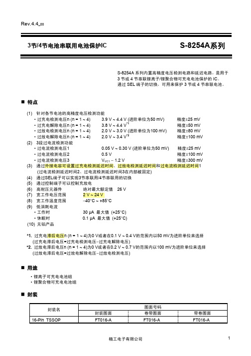
S8254A_锂电池充电芯片
2
精工电子有限公司
Rev.4.4 产品型号的构成
1. 产品名 S-8254A xx FT TB G
3节/4节电池串联用电池保护IC S-8254A系列
卷带规格中的IC置向*1 封装简称 FT : 16-Pin TSSOP 序列号*2 按AA ~ ZZ顺序设置 *1. *2. 请参阅卷带图。 请参阅“2. 产品名目录”。
DS2781芯片资料
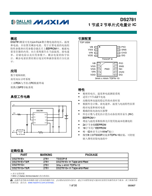
-0.3V to +12V -0.3V to +6.0V
20mA -40°C to +85°C -55°C to +125°C See JEDEC J-STD-020
Stresses beyond those listed under “Absolute Maximum Ratings” may cause permanent damage to the device. These are stress ratings only, and functional operation of the device at these or any other conditions beyond those indicated in the operational sections of the specifications is not implied. Exposure to the absolute maximum rating conditions for extended periods may affect device.
RECOMMENDED DC OPERATING CHARACTERISTICS
(VDD = 2.5V to 10V, TA = -20°C to +70°C, unless otherwise noted. Typical values are at TA = +25°C)
PARAMETER
SYMBOL CONDITIONS
(Note 1)
(Note 1)
+2.5 -0.3 -0.3
2.5
-0.3
+10 VPLS + 0.3
+5.5
20V转5V,20V转3.3V,20V转3V的降压芯片和LDO芯片
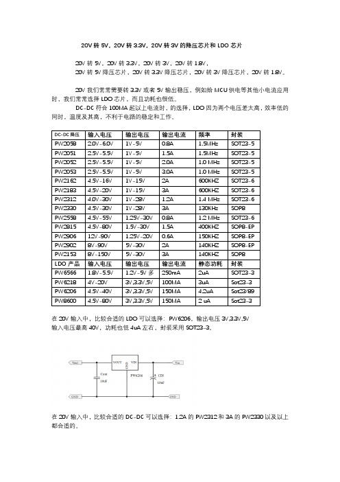
20V转5V,20V转3.3V,20V转3V的降压芯片和LDO芯片
20V转5V,20V转3.3V,20V转3V,20V转1.8V,
20V转5V降压芯片,20V转3.3V降压芯片,20V转3V降压芯片,20V转1.8V。
20V我们常常需要转3.3V或者5V输出稳压,例如给MCU供电等其他小电流应用时,我们常常选择LDO芯片,而且功耗也很低。
DC-DC符合100MA起以上电流时,的选择,LDO因为两个电压差太高,效率低的同时,温度及其高,不利于电路的稳定和工作。
在20V输入中,比较合适的LDO可以选择:PW6206,输出电压3V,3.3V,5V
输入电压最高40V,功耗也低4uA左右,封装采用SOT23-3。
在20V输入中,比较合适的DC-DC可以选择:1.2A的PW2312和3A的PW2330以及以上都合适的。
PW2312是一颗DC-DC同步降压转换器芯片,输入电压范围4V-30V,最大负载电流1.2A,可调输出电压,频率1.4MHZ高频率,可采用贴片电感,节省空间,采用SOT23-6封装形式。
LC51(SOP8)车充IC系列

电性能参数(VIN = 12V, TA = +25°C, 除非另外注明。)
参数
符号
测试条件
最小值
待机电流
ISD
VEN ≤ 0.3V
静态电流
IQ
VEN ≥ 2.6V, VFB =
1.0V
反馈电压
VFB
4.75V ≤ VIN ≤ 27V 0.900
反馈过压阈值
VFB_OVP
误差放大器电压增益 AEA
误差放大器跨导
内部框架图
功能描述
LC51H 是一种电流逐步减缓的同步整流型校准器。它控制输入 4.5V 到 27V 的输入电 压输出低至 0.925V,并且提供 2A 负载电流。其使用电流控制模式校准输出电压。输出电 压在 FB 端通过一个电阻分压检查并且经过内部传导式误差放大器放大。COMP 引脚电流 被用来与内部测量过的开关电流相比较以用来控制输出电压。
0.925 1.1 480 800 130 130
3.4 1.1 3.5 340 100 90 1.5 200 2.5 200 4.20 200 6 15 160
最大值 3.0 1.5 0.950
10 --
380
2.0 2.7 4.40
单位 uA mA
V V V/V uA/V mΩ mΩ uA A A A/V kHz kHz % V mV V mV V mV uA mS °C
DMAX
VFB = 1.0V
使能端关闭电压
VEN RisingLeabharlann 1.1使能关断阈值电压滞环
使能滞欠压锁定阈值
2.2
使能滞欠压锁定
输入低电压锁定
VIN Rising
3.80
输入欠电压锁定
SD8950A 同步降压2A锂电管理IC

直流电特性
(如无特别说明,VCC = 5V 5%,TA = 25℃) 最大 值 6.5 500 280 280 4.242 1100 2200 -5 ±2
符号 Vcc
参数 输入电源电压 输入电源电流 充电模式
条件
最小值 3.8
典型值 5 250 220 190
单位 V uA uA uA V mA mA uA uA mA V mV V mV mV mV mA mA
再充电电池门限电压 振荡频率 P MOSFET“导通”电阻 N MOSFET“导通”电阻 限定温度模式中的结温 软启动时间 再充电比较器滤波时间 终止比较器滤波时间
VFLOAT-VRECHRG
140 1.3
VBAT高至低 IBAT降至ICHR/10一下
0.8 0.8
1.8 1.8
4 4
ms ms
5 / 11
2A 1.5MHz 同步降压型锂离子电池充电器 SD8950A
工作原理
SD8950A 是一款面向5V交充适配器的2A锂 离子电池充电器。它是采用1.5MHz固定频率的同 步降压型转换器,利用芯片内部的功率晶体管对 电池进行涓流、恒流和恒压充电。充电电流可以 用外部电阻编程设定, 最大持续充电电流可达2A, 不需要另加防倒灌二极管。具有高达90%以上的 充电效率,且自身发热量极小。 SD8950A包含两个漏极开路输出的状态指示 端, 充电状态指示端NCHRG和充电满状态指示端 NSTDBY。芯片内部的功率管理电路在芯片结温 超过145℃时自动降低充电电流, 这个功能可以使 用户最大限度的利用芯片处理能力,不用担心芯 片过热而损坏芯片或者损坏外部元器件。 当输入电压大于电源低电压检测阈, SD8950A 开始对电池充电, NCHRG 管脚输出低 电平,表示充电正在进行。如果电池电压低于 2.9V,充电器用小电流对电池进行涓流预充电。 恒流模式对电池充电时,充电电流由RS确定。当 电池电压接近 4.2V 时,充电电流将逐渐减小, SD8950A进入恒压模式。当充电电流减小到充电 结束阈值时,充电周期结束,NCHRG端输出高阻 态,NSTDBY端输出低电平。充电结束阈值是恒 流充电的电流的10%。 当电池电压降到再充电阈值以下时, SD8950A自动开始新的充电周期。芯片内部的高 精度的电压基准源,误差放大器和电阻分压网络 确保电池端调制电压的进度在1%以内,满足了锂 离子电池和锂聚合物电池精确充电的要求。当输 入电压掉电或者输入电压低于电池电压时,充电 器进入低功耗的睡眠模式,电池端消耗的电流小 于3uA,从而增加了待机时间。 表1:Rs及其对应的恒流充电电流 图 6 设定电阻器和充电电流采用下列公式来计算: SD8950A
LT8309 二次侧同步充电驱动器说明书

Typical applicaTionFeaTuresDescripTionSynchronous Rectifier DriverThe L T ®8309 is a secondary-side synchronous rectifier driver that replaces the output rectifier diode in a flyback topology. By replacing the diode with a N-channel MOSFET, applications are no longer restricted by the heat constraints of the output diode. The IC replicates the behavior of a diode by sensing the drain-to-source voltage to determine when the current becomes negative. The LT8309's low minimum on- and off-times help improve noise immunity. The fast propagation delay of 26ns allows applications to operate in discontinuous conduction mode (DCM) and critical conduction mode (CrCM). The gate driver features a 0.8Ω pull-down device for fast turn-offs. The 40V V CC rating allows the part to be driven from the output volt-age or the rectified drain voltage of the MOSFET. A low quiescent current of 400µA maximizes efficiency at low output currents.40W, 5V Isolated Telecom SupplyEfficiency vs Load CurrentapplicaTionsnWorks with DCM and BCM/CrCM Conduction Mode Flyback Topologies n V CC: 4.5V to 40V n Supports Up to 150V MOSFETs n 26ns Turn-Off Propagation Delayn Accurate Minimum On and Off Timers for Reliable Operationn Adjustable and Accurate T rip Point: +5mV to –30mV n 1Ω Gate Driver Pull-Down n SOT-23 5-Lead PackagenHigh Output Current Flybacks n High Efficiency FlybacksL , L T, L TC, L TM, Linear Technology and the Linear logo are registered trademarks ofLinear Technology Corporation. All other trademarks are the property of their respective owners.OUT +, 8AOUT –VLOAD CURRENT (A)065E F F I C I E N C Y (%)708090123465775851009588309 TA01bpin conFiguraTionabsoluTe MaxiMuM raTingsV CC ............................................................................40V INTV CC GATE ............................................................10V DRAIN .....................................................................150V Maximum Junction Temperature ..........................125°C Operating Temperature Range (Note 2)LT8309E ............................................–40°C to 125°C LT8309I .............................................–40°C to 125°C LT8309H ............................................–40°C to 150°C Storage Temperature Range ..................–65°C to 150°C(Note 1)GATE 1GND 2TOP VIEWS5 PACKAGE5-LEAD PLASTIC TSOT-23INTV CC 35 DRAIN4 V CCθJA = 215°C/WorDer inForMaTionLEAD FREE FINISH TAPE AND REEL PART MARKING*PACKAGE DESCRIPTION TEMPERATURE RANGE LT8309ES5#PBF LT8309ES5#TRPBF L TGFZ 5-Lead Plastic TSOT-23–40°C to 125°C LT8309IS5#PBF LT8309IS5#TRPBF L TGFZ 5-Lead Plastic TSOT-23–40°C to 125°C LT8309HS5#PBFLT8309HS5#TRPBFL TGFZ5-Lead Plastic TSOT-23–40°C to 150°CConsult L TC Marketing for parts specified with wider operating temperature ranges. *The temperature grade is identified by a label on the shipping container.For more information on lead free part marking, go to: /leadfree/For more information on tape and reel specifications, go to: /tapeandreel/elecTrical characTerisTicsNote 1: Stresses beyond those listed under Absolute Maximum Ratings may cause permanent damage to the device. Exposure to any Absolute Maximum Rating condition for extended periods may affect device reliability and lifetime.Note 2: The LT8309E is guaranteed to meet performance specifications from 0°C to 125°C operating junction temperature. Specifications over the –40°C to 125°C operating junction temperature range are assured by design, characterization and correlation with statistical process controls. The LT8309I is guaranteed over the full –40°C to 125°C operating junctionPARAMETER CONDITIONSMIN TYP MAX UNITSInput Voltage Range l4.540V V CC Quiescent Current Not Switching, INTV CC = 8V 300345µA Comparator Turn-On Threshold R S = 0Ωl –69–57–45mV Turn-Off Threshold R S = 0Ω l17 162125 28mV mV Drain Voltage Latch Reset R S = 0Ω1.21V Minimum Off-Time 7595115ns Minimum On-Time 310360410ns Drain CurrentOut of Pinl 9.51010.5µA INTV CC Linear Regulator INTV CC Quiescent Current Not Switching, INTV CC = 8V100117µA INTV CC Voltage Range 4.510V INTV CC Regulation Voltage l6.877.2V INTV CC UVLO4.03V Dropout (V CC to INTV CC )I INTVCC = –10mA, V IN = 7V1 1.3 1.6V Current Limit l 304255mAGate DriverTurn-On Propagation Delay (t D(ON))R S = 0Ω, –100mV OD , V DS to V GATE 3140ns Turn-Off Propagation Delay (t D(OFF))R S = 0Ω, –100mV OD , V DS to V GATE 2636ns t r GATE Driver Output Rise Time C L = 3300pF 21ns t f GATE Driver Output Fall Time C L = 3300pF11ns Pull-Up Resistance 2.7ΩPull-Down Resistance0.8ΩThe l denotes the specifications which apply over the full operating temperature range, otherwise specifications are at T A = 25°C.temperature range. The LT8309H is guaranteed over the full –40°C to 150°C operating junction temperature range. High junction temperatures degrade operating lifetimes. Operating lifetime is derated at junction temperatures greater than 125°C.Note 3: The LT8309 includes overtemperature protection that is intended to protect the device during momentary overload conditions. Junction temperature will exceed 150°C when overtemperature protection is active. Continuous operation above the specified maximum operating junction temperature may impair device reliability.TEMPERATURE (°C)–500V C C I Q C U R R E N T (µA )50150250–252550100751251002003504503004001508309 G01TEMPERATURE (°C)–50I N T V C C I Q C U R R E N T (µA )–252550100751251508309 G02408012016020020601001401800I N T V C C V O L T A G E (V )24681357V CC VOL TAGE (V)102030408309 G04TEMPERATURE (°C)–503.0T H R E S H O L D V O L T A G E (V )3.54.5–252550100751255.04.01508309 G05INTV CC CURRENT (mA)I N T V C C R E G U L A T O R D R O P O U T (V )1.51020302.51.00.52.0408309 G06TEMPERATURE (°C)–500I N T V C C D R O P O U T (V )1.0–252550100751252.00.51.51508309 G07TEMPERATURE (°C)–500I N T V C C C U R R E N T L I M I T (m A )103050–252550100751252040601508309 G08Typical perForMance characTerisTicsINTV CC Voltage vs V CC VoltageINTV CC Undervoltage Lockout vs TemperatureINTV CC Regulator Dropout vs INTV CC CurrentINTV CC Dropout vs TemperatureINTV CC Current Limit vs TemperatureMinimum On-Time and Off-Time vs TemperatureI VCC vs TemperatureI INTVCC vs TemperatureINTV CC vs TemperatureTEMPERATURE (°C)–100–50T I M E (n s )501001502008309 G0950150250100200350300400TEMPERATURE (°C)–506.0I N T V C C V O L T A G E (V )6.46.87.2–252550100751258.07.86.26.67.07.47.61508309 G03TEMPERATURE (°C)–500D R A I N P I N C U R RE N T (µA )2612–252550100751251048141508309 G10TEMPERATURE (°C)–50T U R N -O N T H R E S H O L D (m V )–252550100751251508309 G11–80–70–60–50–40–75–65–55–45TEMPERATURE (°C)–50T U R N -O F F T H R E S H O L D (m V )–252550100751251508309 G12102030405152535TEMPERATURE (°C)–501.00T H R E S H O L D V O L T A G E (V )1.101.201.30–252550100751251.401.051.151.251.351508309 G13Typical perForMance characTerisTicsLatch Reset Thresholdvs TemperatureGATE Rise and Fall Time vs ChargeGATE Current vs ChargeDRAIN Pin Current vs TemperatureComparator Turn-On Thresholdvs TemperatureComparator Turn-Off Threshold vs Temperature0T I M E (n s )50150200100CHARGE (nC)6012030901508309 G14T I M E (n s )1.02.03.04.00.51.52.53.5CHARGE (nC)8309 G150601203090150block DiagraMpin FuncTionsGATE (Pin 1): N-Channel MOSFET Gate Driver Output. Switches between INTV CC and GND. Driven to GND during undervoltage lockout of INTV CC . GND (Pin 2): Ground.INTV CC (Pin 3): Regulated Supply for Internal Loads, and GATE Driver. Supplied from V CC and regulates to 7V (typical). INTV CC must be bypassed with a 4.7µF capacitor placed close to the pin.V CC (Pin 4): Input Voltage. This pin supplies current to the internal start-up circuitry and to the INTV CC LDO. This pin must be locally bypassed with a capacitor.DRAIN (Pin 5): Current Sense Pin. This pin sensesthe voltage across the drain-to-source of the externalN-channel MOSFET. A series resistor is needed to set the offset voltage and needs to be at least 800Ω. The offset is equal to:20mV •1−R 20008309 F01GND V OFFSETD(ON)D(OFF)operaTionThe LT8309 is a synchronous rectifier designed for boundary conduction mode/critical conduction mode and discontinuous mode flyback converters. Existing solutions use a pulse signal from the primary side to control the synchronous rectifier, but the LT8309 senses the drain-source voltage of the MOSFET to control the synchronous rectifier. This technique not only elimi-nates a transformer, but allows it to work with Linear Technology’s line of no-opto critical conduction flyback converters. Synchronous rectification improves ef-ficiency and more importantly increases the maximum output current when compared to nonsynchronous designs.The LT8309 imitates the behavior of a diode but re-places the forward voltage with the R DS(ON) of an externalN-channel MOSFET. The LT8309 includes an LDO, a very fast comparator and a powerful gate driver.An external resistor connects the part’s DRAIN pin to the drain of the MOSFET. This resistor sets the trip point of the comparator with a precise internal current source. To set the trip point to –10mV, a 3000Ω resistor is needed. The trip point decreases by 1mV for every 100Ω added to this drain resistor. This trip point will be referred to as V OFFSET . Figure 1 shows the drain waveform on top and the gate waveform on the bottom. The gate node goes high when the drain node goes 74mV below the V OFFSET . The comparator’s output is ignored for a minimum on-time to eliminate the chance that ringing triggers the comparator. After the minimum on-time, the comparator is ready to trigger at the V OFFSET voltage. Once the drain voltage goes above V OFFSET , the gate turns off after a very fast propaga-tion delay, t D(OFF). The body diode begins to conduct again before the current reaches 0A. The drain voltage needs to go above 1.21V and then wait for the minimum off-time before the comparator is re-enabled.Figure 1. Drain and Gate WaveformsOUTV operaTionUndervoltage LockoutThe part features a INTV CC undervoltage lockout (UVLO) to prevent switching until the INTV CC voltage is above 4V. INTV CC LDOAn internal LDO regulator provides a regulated 7V output from the V IN pin to the INTV CC pin. An output capacitor is needed to provide the current needed for the gate driver. A 4.7µF capacitor is recommended and must be placed as close as possible to the INTV CC pin. The current limit for the LDO is 42mA.MOSFET SelectionA MOSFET’s R DS(ON) is important to the operation of the LT8309. The drain-source voltage is used to determine when to turn off the MOSFET. The peak current through the MOSFET times the MOSFET’s R DS(ON) should be above 75mV. When this voltage is too low, the high speed comparator may trip early due to ringing on the DRAIN pin. When this voltage is too high, the MOSFET dissipates a large amount of power which causes efficiency to go down and may cause thermal issues with the MOSFET.Setting the DRAIN Pin ResistorThe DRAIN pin resistor sets when the LT8309 turns off the MOSFET. The trip point, V OFFSET , is set with the fol-lowing equation:V OFFSET = 20mV – 10µA • R DRAINR DRAIN is the resistor connected between the drain of the MOSFET and the DRAIN pin of the part. R DRAIN needs to be at least 800Ω to operate correctly. For most applications, V OFFSET should be set at –5mV. High R DS(ON) MOSFETs may require a more negative V OFFSET voltage to keep the drain-to-source current from reversing. If the current is reversing, decrease V OFFSET in 5mV steps to eliminate the cross-conduction. Short-Circuit OperationIn the Typical Application diagram on Page 1, the V CC pin is connected to the output of the flyback converter. During an output short-circuit condition, the LT8309 is off and the body diode of the MOSFET must handle the short-circuit condition. This puts additional thermal requirements on the MOSFET. The drain voltage of the MOSFET is equal to V IN /N in short-circuit and capable of powering the LT8309 with the circuit in Figure 2. This allows the LT8309Figure 2. Short-Circuit Application CircuitoperaTionFigure 3. Demo Board Topside Silkscreen Figure 4. Demo Board Topside Metalto operate during a short, and the current will flow throughthe low resistance channel of the MOSFET instead of itsbody diode. Make sure to use a resistor in series with thediode to keep V CC below 40V.Layout ConsiderationsThe main current loop is the MOSFETs drain-to-sourcecurrent. This should not share the same ground path asthe LT8309. The drain resistor needs to sense directly atthe drain of the MOSFET and not have any current of thedrain current flow through its metal trace. The drain nodeof the MOSFET is used as the heat sink and will need tobe sized according to the power dissipation requirements.Figure 3 is an example layout of the LT8309.Effects of the Body DiodeWhen the discontinuous ring voltage goes below ground,the body diode of the primary-side MOSFET turns on andbegins to conduct current. This diode clamps the voltageto a diode drop below ground. When the current reversesdirection, the diode does not turn off immediately, andconducts current in the opposite direction for a small periodof time. This is known as the reverse-recovery time. Duringthis time, the magnetizing inductance of the transformerstores energy just like it does when the MOSFET turnson. When the primary-side body diode finally turns off,the energy is transferred to the secondary side and maybe enough to turn on the body diode of the secondaryMOSFET. Then, the LT8309 turns on its MOSFET for asecond time. Since this happens during the discontinuousring, the primary side may turn on during this time andcause cross conduction. If this problem does occur, oneway to improve the reverse-recovery time of the primaryside’s MOSFET is to add a parallel Schottky diode, whichwill conduct most of the current and turn off much fasterthan the body diode. Another way of eliminating this issueis by sizing the turns ratio so that the discontinuous ringnever goes below ground.Typical applicaTions60W, 12V Output, Isolated Telecom SupplyV, 5AOUT–Typical applicaTions40W, 5V Isolated Telecom SupplyV, 8AOUT–118309faFor more information /L T8309package DescripTionPlease refer to /designtools/packaging/ for the most recent package drawings.0.30 – 0.45 TYP5 PLCS (NOTE 3)(NOTE 3)S5 TSOT-23 0302 NOTE:1. DIMENSIONS ARE IN MILLIMETERS2. DRAWING NOT TO SCALE3. DIMENSIONS ARE INCLUSIVE OF PLATING4. DIMENSIONS ARE EXCLUSIVE OF MOLD FLASH AND METAL BURR5. MOLD FLASH SHALL NOT EXCEED 0.254mm6. JEDEC PACKAGE REFERENCE IS MO-1930.620.95RECOMMENDED SOLDER PAD LAYOUTPER IPC CALCULATORS5 Package3-Lead Plastic TSOT-23(Reference LTC DWG # 05-08-1635)128309faFor more information /L T8309138309faFor more information www.linear .com/L T8309Information furnished by Linear Technology Corporation is believed to be accurate and reliable. However, no responsibility is assumed for its use. Linear Technology Corporation makes no representa-tion that the interconnection of its circuits as described herein will not infringe on existing patent rights.revision hisToryREV DATE DESCRIPTION PAGE NUMBERA11/14Added H-Grade Version2, 3148309faFor more information www.linear .com/L T8309LINEAR TECHNOLOGY CORPORA TION 2014LT 1114 REV A • PRINTED IN USALinear Technology Corporation1630 McCarthy Blvd., Milpitas, CA 95035-7417(408) 432-1900 ● FAX : (408) 434-0507 ● www.linear .com/L T8309relaTeD parTsTypical applicaTionPART NUMBER DESCRIPTIONCOMMENTSLT3748100V Isolated Flyback Controller5V ≤ V IN ≤ 100V, No-Opto Flyback, MSOP-16 PackageLT3798Offline Isolated No-Opto-Coupler Flyback Controller with Active PFCV IN and V OUT Limited Only by External Components, MSOP-16 Package LT3799/LT3799-1Offline Isolated Flyback LED Controller with Active PFC V IN and V OUT Limited Only by External Components, MSOP-16 Package LT3957A/LT395840V/80V Flyback/Boost/Inverting/SEPIC Converter Monolithic with Integrated 5A/3.3A SwitchLT3573/LT3574/ LT357540V Isolated Flyback ConvertersMonolithic No-Opto Flybacks with Integrated 1.25A/0.65A/2.5A Switch LT3757A/LT3759/ LT375840V/100V Boost, Flyback, SEPIC and Inverting Controllers Universal Controllers with Small Package and Powerful Gate Drive LT8302Micropower No-Opto Isolated Flyback Converter2.8V ≤ V IN ≤ 42V, with Integrated3.6A, 65V DMOS Power Switch, 106µA Quiescent Current, SO-8 Package33W, 3.3V Isolated Telecom SupplyOUT +, 10AOUT –V。
二合一移动电源专用IC芯片

应用说明
温充电模式
CH8813 内部集成了温度反馈环路,充电时,如果芯片内 部的温度升高到 120℃,充电电流会随着芯片的温度升高 而降低,从而减小系统功耗,降低温升,当温度升高到 140℃时,充电电流减小为零,由于温度反馈控制, IC 工作温度最终会稳定在 120℃~140℃之间的某个值。该 功能允许用户提高给定电路板功率处理能力的上限而没 有损坏 IC 的风险。在保证充电器将在最坏情况条件下自 动减小电流的前提下,可根据典型(而不是最坏情况) 环境温度来设定充电电流。
PCB 设计参考
1、5V 输出端的 USB 外壳不能接 GND,需浮空; 2、整个 PCB 建议敷铜散热,散热面积尽量大; 3、BAT 电容靠近 IC,BAT+和 BAT-需先经过 BAT 电容 再到 IC,各 GND 走线要尽量粗,空余的地方全部走 GND; 4、电容 C3 到电感 L1 再到 SW 的路径走线要尽量短且 线要粗; 5、电感 L1,SS34 与电容形成的环路走线要短,环面积 要小; 6、大电流通路,如 BAT+、L1 到 SW 引脚的通路,BAT+、 L1、D1 、负载到 OUTN 引脚的通路路径短且粗,尽量不 要过过孔; 7、芯片底部散热焊盘同时也是芯片的 GND,需与 PCB 有良好焊接。
VBAT=3.7V ILOAD=1A 温度上升 ILED=5mA
4.8
10 5.2
升压电路工作频率 FOSC 注 2 :预设电池充电电压有 4.2V 和 4.35V 两种规格
Ver1.1
Nanjing chiphighlights Electronics
4
CH8813 南京芯亮点电子有限公司充放电双灯指示小体积移动电源解决方案
应用
USB接口专用固定5V 1.8A 150KHz 45V降压型DC-DC转换器 XL2001 说明书

USB 接口专用固定5V/1.8A 150KHz 45V降压型DC-DC转换器XL2001特点⏹8V到45V宽输入电压范围⏹固定5V输出电压⏹最大1.8A开关电流⏹固定150KHz开关频率⏹内置功率MOS⏹效率高达92%⏹内置输出短路保护功能⏹出色的线性与负载调整率⏹内置热关断功能⏹内置限流功能⏹SOP8封装应用⏹车载充电器⏹电池充电器⏹USB电源描述XL2001是一款高效降压型DC-DC转换器,固定150KHz开关频率,可以提供最高1.8A输出电流能力,具有低纹波,出色的线性调整率与负载调整率特点。
XL2001内置固定频率振荡器与频率补偿电路,简化了电路设计。
XL2001内置输出短路保护功能。
当输出短路时,芯片关机。
内部补偿模块可以减少外围元器件数量。
图1.XL2001封装USB 接口专用固定5V/1.8A 150KHz 45V 降压型DC-DC 转换器 XL2001引脚配置FB NC VC SWSW GND GND 12345678图2. XL2001引脚配置表1.引脚说明引脚号 引脚名称 描述1 FB 反馈引脚,参考电压为5V 。
2 NC 无连接。
3VC内部电压调节器旁路电容引脚,需要在VIN 与VC 引脚之间连接1个1uF 电容。
4 VIN 电源输入引脚,支持DC8V~45V 宽范围电压工作,需要在VIN 与GND 之间并联电解电容以消除噪声。
5,6 SW 功率开关输出引脚,SW 是输出功率的开关节点。
7,8 GND接地引脚。
USB 接口专用固定5V/1.8A 150KHz 45V 降压型DC-DC 转换器 XL2001方框图Switching current Convert DC currentVCVINOSPCurrent Sense3.3V Regulator 1.25V ReferenceStart UpCOMPOscillator150KHz/45KHzEAFBGNDRS Latch and Driver3.3V 1.25VPORVOSPSWSwitch1:1000ShutdownThermal Shutdown图3. XL2001方框图典型应用XL2001CIN47uF/50VCOUT100uF/16VD1SS36C1105C210545,67,81VIN3VOUT=5V/0~1.8AVINVC SWGNDFBCC 105图4. XL2001系统参数测量电路(VIN=8V~45V, VOUT=5V/1.8A)USB接口专用固定5V/1.8A 150KHz 45V降压型DC-DC转换器XL2001订购信息产品型号打印名称封装方式包装类型XL2001E1 XL2001E1 SOP8 2500/4000只每卷XLSEMI无铅产品,产品型号带有“E1”后缀的符合RoHS标准。
TP5100U 2A开关降压锂电池充电器芯片说明书
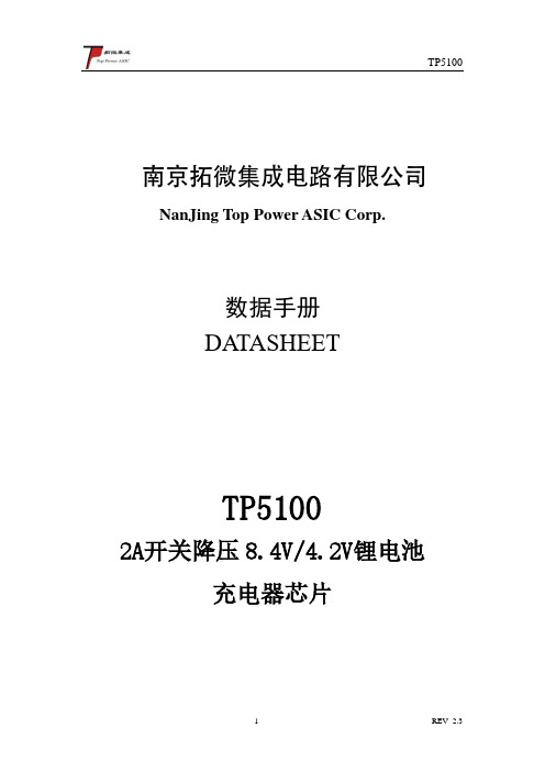
南京拓微集成电路有限公司NanJing Top Power ASIC Corp.数据手册DATASHEETTP51002A开关降压8.4V/4.2V锂电池充电器芯片概述TP5100是一款开关降压型双节8.4V/单节4.2V 锂电池充电管理芯片。
其QFN16超小型封装与简单的外围电路,使得TP5100非常适用于便携式设备的大电流充电管理应用。
同时,TP5100内置输入过流、欠压保护、芯片过温保护、短路保护、电池温度监控。
TP5100具有5V-12V 输入电压,对电池充电分为涓流预充、恒流、恒压三个阶段,涓流预充电电流、恒流充电电流都通过外部电阻调整,最大充电电流达2A 。
TP5100采用频率400kHz 的开关工作模式使它可以使用较小的外围器件,并在大电流充电中仍保持较小的发热量。
TP5100内置功率PMOSFET 、防倒灌电路,所以无需防倒灌肖特基二极管等外围保护。
特性■双/单节8.4V/4.2V 锂电池充电■内置功率MOSFET,开关型工作模式,器件发热少,外围简单■可编程充电电流,0.1A--2A ■可编程预充电电流,20%--100%■红绿LED 充电状态指示■芯片温度保护,过流保护,欠压保护■电池温度保护、电池短路保护■开关频率400KHz ,可用电感4.7uH-22uH ■PWR_ON-电源、电池供电切换控制■小于1%的充电电压控制精度■涓流、恒流、恒压三段充电,保护电池■采用QFN16 4mm*4mm 超小型封装绝对最大额定值■静态输入电源电压(VIN ):18V ■BA T :0V ~9V■BA T 短路持续时间:连续■最大结温:120℃■工作环境温度范围:-20℃~85℃■贮存温度范围:-30℃~125℃■引脚温度(焊接时间10秒):260℃应用■便携式设备、各种充电器■智能手机、PDA 、移动蜂窝电话■MP4、MP5播放器、平板电脑■航模、电动工具、对讲机典型应用VINBATTP5100CHRGSTDBY LXVSVIN=12V10uF1K1415 1. 4. 5. 162.3897GND TS1110u F10uHRs=0.06710u FVS 8.4V 2SLiG RCSR N T CR 1VREG RTRICK0.1uF1012130.1uF0.1u F0.1u FPWR_ON-6BAT+S S 34R 250K0.2Ω(建议两个0.4并联,1206封装)3Ω0.1nF 图1 TP5100为8.4V 双节锂离子电池1.5A 充电应用示意图(如需更高耐压,LX 端RC 电路需接入)VINBATTP5100CHRGSTDBYLXVSVIN=5-12V10uF1K1415 1. 4. 5. 162.3897GND TS1110u F10uHRs=0.06710u FVS4.2V LiG RCSR N T CR 1VREG RTRICK0.1uF1012130.1uF0.1u F0.1u FPWR_ON-6BAT+S S 34R 250K3Ω0.1nF 0.2Ω(建议两个0.4并联,1206封装)图2 TP5100为4.2V 单节锂离子电池1.5A 充电应用示意图封装/订购信息16引脚4mm*4mmQFN16封装顶视图(散热片接地)订单型号TP5100-QFN16器件标记 TP5100 实物图片TP5100功能方框图图3 TP5100功能框图电特性表1 TP5100电特性能参数凡注●表示该指标适合8.4V 、4.2V 模式,否则仅指8.4V ,T A =25℃,VIN=9V ,除特别注明。
S-8215A系列电池保护IC-ABLICInc

3. 1 TMSOP-8 表2 过充电检测 输出方式 延迟时间 [t CU ] CMOS输出 S-8215AAA-K8T2U 4.300 V 0.300 V 4.0 s N 沟道开路漏极输出 S-8215AAB-K8T2U 4.275 V 0.050 V 2.0 s CMOS输出 S-8215AAC-K8T2U 4.150 V 0.250 V 1.0 s CMOS输出 S-8215AAD-K8T2U 4.350 V 0.250 V 2.0 s N 沟道开路漏极输出 S-8215AAE-K8T2U 4.325 V 0.050 V 1.0 s CMOS输出 S-8215AAF-K8T2U 4.220 V 0.100 V 1.0 s N 沟道开路漏极输出 S-8215AAH-K8T2U 4.325 V 0.300 V 1.0 s CMOS输出 S-8215AAI-K8T2U 4.250 V 0.250 V 1.0 s CMOS输出 S-8215AAJ-K8T2U 4.400 V 0.100 V 2.0 s N 沟道开路漏极输出 S-8215AAK-K8T2U 4.150 V 0.050 V 2.0 s N 沟道开路漏极输出 S-8215AAL-K8T2U 4.150 V 0.500 V 2.0 s CMOS输出 S-8215AAM-K8T2U 4.150 V 0.050 V 2.0 s CMOS输出 S-8215AAN-K8T2U 4.150 V 0.500 V 2.0 s CMOS输出 S-8215AAO-K8T2U 4.350 V 0.250 V 4.0 s CMOS输出 S-8215AAP-K8T2U 4.275 V 0.500 V 1.0 s CMOS输出 S-8215AAQ-K8T2U 4.275 V 0.050 V 1.0 s CMOS输出 S-8215AAR-K8T2U 4.500 V 0.100 V 4.0 s CMOS输出 S-8215AAS-K8T2U 4.275 V 0.200 V 2.0 s CMOS输出 S-8215AAT-K8T2U 4.275 V 0.050 V 2.0 s CMOS输出 S-8215AAU-K8T2U 3.750 V 0.100 V 1.0 s CMOS输出 S-8215AAV-K8T2U 4.300 V 0.300 V 1.0 s 备注 除上述产品以外,其他产品的检测电压也是可以改变的。详情请向本公司营业部咨询。 产品名 过充电检测电压 过充电滞后电压 [V CU ] [V HC ]
SD45230骊微车充IC

0.9V FB
COMP
3
++-
5V
5V
REGULATOR
PWM Comparator
SQ Logic Control
R
Driver
0.4V FB
OVP
SCP
OTP
BS 7
SW
8
GND
4
极限参数 (Tamb=25°C)
参数 输入端工作电压范围 开关端电压范围 自举端电压范围 补偿端电压 反馈端电压 正采样端电压范围 负采样端电压范围 工作环境温度范围 贮存温度范围
Rline R3 =
160μ⋅ R2
0.835 ⋅ R3 R4 =
VOUT - 0.835 如导线电阻 Rline 为 50mΩ,图 1 中 R2=33.3mΩ(2.25A 限流值),VOUT=5V,则可计算出:R3=9.4k, R4=1.9k,如图 1 所示取 R3=10k,R4=2k。
元件的选择
* 输出过压保护
- 1、下载文档前请自行甄别文档内容的完整性,平台不提供额外的编辑、内容补充、找答案等附加服务。
- 2、"仅部分预览"的文档,不可在线预览部分如存在完整性等问题,可反馈申请退款(可完整预览的文档不适用该条件!)。
- 3、如文档侵犯您的权益,请联系客服反馈,我们会尽快为您处理(人工客服工作时间:9:00-18:30)。
8L Packag ble in SOP-e SD8925G e SD8925G 30V, the SD8925G ac G is a sy e SD89254% Efficie2.1A 10V~30V Wide Range Synchronous Buck ControllerF e a t u r Wide I Up to Progra to up t No Loo Progra Cable Therm Availa A p p l i c a Car Ch Pre-Re Distrib BatteryesInput Voltag 9n ammable Sw to 500kHz op Compen ammable cu Compensat mal Shutdow t i o n sharger / Ada egulator for buted Power y Chargere Range: 10ncy witching Freq sation Requ rrent limit tion from 0n aptor Linear Regu r Systems 0V to 30Vquency up uired Ω to 0.3Ω e ulatorsTh re Op to ou re prsy eff pr sta Th re Ot pr sh Th indD e s c r i p t i h gulator from perating with X utput curren gulation.rogrammable ynchronous ficient des rovides fast t abilization.h adily availab ther feature rogrammable hutdown.h dustry stando nn m a high h an input v h nt with exc The switc e from 150 k architecture signs. Curr transient res requires a ble standard es include e current converter dard SOP-8Lnchronous voltage inp voltage rang hieves 2.1A cellent load ching freq kHz to 500 k e provides rent mode sponse and a minimum d external co cable com limit and rs are availa L packages.step down put supply. e from 10V continuous d and line quency iskHz and the for highly operationeases loop number ofomponents.mpensation, d thermalable in theSD8925GShouding············T y p i c a l A p p l i c a t i o n C i r c u i t * The output voltage is set by R2 and R3: V OUT = 1.21V • [1 + (R2/R3)].The SD8925G is guaranteed to meetP i n A s s i g n m e n ta n d D e s c r i p t i o nA b s o l u t e M a x i m u m R a t i n g s (N o t e 1)Input Supply Voltage ....................................................................................................-0.3V~ 35V FB, ILIM, RT Voltages.................................................................................................... -0.3V ~ 6V SW Voltage ........................................................................................................-0.3V ~ (VIN + 1V) Operating Temperature Range (Note 2)………...………………………………………-40℃ ~ +85℃Storage Temperature Range.................................................................................. -65℃ ~ +150℃ Junction Temperature Range………………………………………………...……………..……...+150℃ Lead Temperature (Soldering, 10 sec.).................................................................................. +265℃ Note 1: Stresses beyond those listed Absolute Maximum Ratings may cause permanent damage to the device. Exposure to any Absolute Maximum Rating condition for extended periods may affect device reliability and lifetime. Note 2: performance specifications from 0℃ to 70℃. Specifications over the –40℃to 85℃ operating temperature range are assured by design, characterization and correlation with statistical process controls.PINNAMEDESCRIPTION 1 FB Feedback2 RT Frequency Setting3 ILIM Current Limit4 VIN Input Supply Voltage5, 6 SW Switch Node7, 8GNDGround·······Main Supply Pin. The SD8925G operates from P i n F u n c t i o n s FB (Pin 1): Feedback Pin. Receive the feedback voltage from an external resistive divider across the output. In the adjustable version, the output voltage is fixed. The Output voltage is set by R2 and R3: V OUT = 1.21V • [1 + (R2/R3)].RT (Pin 2): The internal oscillator is set with a single resistor between this pin and the GND pin. ILIM (Pin 3): Monitors current through the low-side switch and triggers current limit operation if the inductor valley current exceeds a user defined value that is set by R LIM and the Sense current sourced out of this pin during operation.VIN (Pin 4): 10V to 30V unregulated input. It must be closely decoupled to GND, with a 47μF or greater ceramic capacitor to prevent large voltage spikesfrom appearing at the input.SW (Pin 5, 6):Switch Node Connection to Inductor. GND (Pin 7, 8): Ground Pin.E l e c t r i c a l C h a r a c t e r i s t i c sOperating Conditions: T A=25, V℃IN=12V, R2=470k, R3=150k, unless otherwise specified.SYMBOL PARAMETER CONDITIONS MIN TYP MAX UNITS V IN Operating Voltage Range 10 30 VI Q QuiescentCurrent I LOAD=0A 101520mAI SHDN ShutdownCurrent 110 150 μA V UVLO Input UVLO Threshold 4.25 4.5 VΔV UVLO UVLOHysteresis 50 100mV V FB RegulatedVoltage 1.188 1.21 1.236 VI FB Feedback Pin Input Current0.05 μAf OSC Oscillator Frequency Range150 500 kHzR T=100k 180 220 260 kHz DC Max Duty Cycle 100 %I LIM-TH Current Limit Sense PinSource Current 7 8.5 10 μAR PFET R DS(ON) of P-Channel FET 65 mΩR NFET R DS(ON) of N-Channel FET 30 mΩT SD Thermal Shutdown TemperatureRising 125 ℃ΔT SD Thermal ShutdownHysteresis 30℃T y p i c a l P e r f o r m a n c e C h a r a c t e r i s t i c sOperating Conditions: T A=25℃, C IN=47μF, C OUT=100μF, L=10μH, unless otherwise noted.Vin=24VVin=12VB l o c k D i a g r amThe SD8925G oscillator frequency is set by a single Continuously running the SD8925G The total power dissipation in SD8925G is limited The SD8925G operates by aA p p l i c a t i o n I n f o r m a t i o nconstant frequency, current mode architecture. The output voltage is set by an external divider returned to the FB pin. An error amplifier compares the divided output voltage with a reference voltage of 1.21V and adjusts the peak inductor current accordingly.During normal operation, the internal P-channel MOSFET is turned on each cycle when the oscillator sets the RS latch, and turned off when the current comparator, resets the RS latch. While the P-channel MOSFET is off, the N-channel MOSFET is turned on until either the inductor current starts to reverse, as indicated by the current reversal comparator or the beginning of the next clock cycle. Thermal Protectionby a thermal protection circuit. When the device temperature rises to approximately 125℃, this circuit turns off the output, allowing the IC to cool. The thermal protection circuit can protect the device from being damaged by overheating in the event of fault conditions. into thermal shutdown degrades device reliability. Current LimitCurrent limit detection occurs during the off-time by monitoring the current through the low-side switch using an external resistor, R LIM . The current limit value is defined by R LIM . If during the off-time the current in the low-side switch exceeds the user defined current limit value, the next on-time cycle is immediately terminated. Current sensing is achieved by comparing the voltage across the low side FET with the voltage across the current limit set resistor R LIM . For example, the current limit value is 2.1A by the R LIM =62k. The current limit value rises when the set resistor R LIM rises. The maximum output current is set by R LIM : R LIM (k Ω) = 24• I MAX (A). Oscillator Frequencyexternal resistor connected between the RT pin and the GND pin. The resistor should be located very close to the device and connected directly to the pins of the IC (RT and GND). An internal amplifier holds the RT pin at a fixed voltage typically 0.6V. The oscillator frequency rises when the resistor R T falls. To determine the timing resistance for a given switching frequency, use the equation below:R T (k Ω)= 22000 /f OSC (kHz)Setting Output VoltageThe output voltage is set with a resistor divider from the output node to the FB pin. It is recommended to use divider resistors with 1% tolerance or better. To improve efficiency at very light loads consider using larger value resistors. If the values are too high the regulator is more susceptible to noise and voltage errors from the FB input current are noticeable. For most applications, a resistor in the 10k Ω to 1M Ω range is suggested for R3. R2 is then given by:R2 = R3 • [(V OUT / V REF ) – 1]where V REF is 1.21V.ments than on what the SD8925G requires to operate.able, the SD8925G integrates aOutput Cable Resistance CompensationTo compensate for resistive voltage drop across the charger's output c simple, user-programmable cable voltage drop compensation using the impedance at the FB pin. Choose the proper feedback resistance values for cable compensation refer to the curve in Figure 1. The delta VOUT voltage rises when the feedback resistance R3 value rises. The delta VOUT voltage rises when the feedback resistance R3 value rises, use the equation below:ΔV OUT (V) = R3(k Ω) • I OUT (A)/635Figure 1. Delta Output Voltage vs. Load CurrentInductor SelectionFor most applications, the value of the inductor will fall in the range of 4.7μH to 47μH. Its value is chosen based on the desired ripple current. Large value inductors lower ripple current and small value inductors result in higher ripple currents. Higher V IN or V OUT also increases the ripple current as shown in equation. A reasonable starting point for setting ripple current is I △L =840mA (40% of 2.1A).The DC current rating of the inductor should be at least equal to the maximum load current plus half the ripple current to prevent core saturation. Thus, a 2.94A rated inductor should be enough for most applications (2.1A + 840mA). For better efficiency, choose a low DC-resistance inductor.Different core materials and shapes will change the size/current and price/current relationship of an inductor. Toroid or shielded pot cores in ferrite or perm alloy materials are small and don’t radiate much energy, but generally cost more than powdered iron core inductors with similar electrical characteristics. The choice of which style inductor to use often depends more on the price vs. size requirements and any radiated field/EMI requireOutput and Input Capacitor SelectionIn continuous mode, the source current of the top MOSFET is a square wave of duty cycle V OUT/V IN. To prevent large voltage transients, a low ESR input capacitor sized for the maximum RMS current must beused. The maximum RMS capacitor current is given by:This formula has a maximum at V IN = 2V OUT, where I RMS = I OUT/2. This simple worst-case condition iscommonly used for design because even significant deviations do not offer much relief. Note that thecapacitor manufacturer’s ripple current ratings are often based on 2000 hours of life. This makes itadvisable to further derate the capacitor, or choose a capacitor rated at a higher temperature thanrequired. Always consult the manufacturer if there is any question.The selection of C OUT is driven by the required effective series resistance (ESR).Typically, once theESR requirement for C OUT has been met, the RMS current rating generally far exceeds the I RIPPLE(P-P)requirement. The output ripple ΔV OUT is determined by:Where f = operating frequency, C OUT = output capacitance and ΔI L = ripple current in the inductor. For afixed output voltage, the output ripple is highest at maximum input voltage since ΔI L increases with inputvoltage.Aluminum electrolytic and dry tantalum capacitors are both available in surface mount configurations. Inthe case of tantalum, it is critical that the capacitors are surge tested for use in switching power supplies.An excellent choice is the AVX TPS series of surface mount tantalum. These are specially constructedand tested for low ESR so they give the lowest ESR for a given volume.Efficiency ConsiderationsThe efficiency of a switching regulator is equal to the output power divided by the input power times100%. It is often useful to analyze individual losses to determine what is limiting the efficiency and whichchange would produce the most improvement. Efficiency can be expressed as: Efficiency = 100% - (L1+L2+ L3+ ...) where L1, L2, etc. are the individual losses as a percentage of input power. Although alldissipative elements in the circuit produce losses, two main sources usually account for most of thelosses: VIN quiescent current and I2R losses. The VIN quiescent current loss dominates the efficiencyloss at very low load currents whereas the I2R loss dominates the efficiency loss at medium to high loadcurrents. In a typical efficiency plot, the efficiency curve at very low load currents can be misleadingsince the actual power lost is of no consequence.1. The VIN quiescent current is due to two components: the DC bias current as given in the electricalcharacteristics and the internal main switch and synchronous switch gate charge currents. The gatecharge current results from switching the gate capacitance of the internal power MOSFET switches.Each time the gate is switched from high to low to high again, a packet of charge ΔQ moves from VIN toground. The resulting ΔQ/Δt is the current out of VIN that is typically larger than the DC bias current.operation of the SD8925G. CheckIn continuous mode, I GATECHG = f (Q T +Q B ) where Q T and Q B are the gate charges of the internal top and bottom switches. Both the DC bias and gate charge losses are proportional to VIN and thus their effects will be more pronounced at higher supply voltages.2. I 2R losses are calculated from the resistances of the internal switches, R SW and external inductor R L . In continuous mode the average output current flowing through inductor L is “chopped” between the main switch and the synchronous switch. Thus, the series resistance looking into the SW pin is a function of both top and bottom MOSFET R DS(ON) and the duty cycle (DC) as follows: R SW = R DS(ON)TOP x DC + R DS(ON)BOT x (1-DC) The R DS(ON) for both the top and bottom MOSFETs can be obtained from the Typical Performance Characteristics curves. Thus, to obtain I 2R losses, simply add R SW to R L and multiply the result by the square of the average output current. Other losses including C IN and C OUT ESR dissipative losses and inductor core losses generally account for less than 2% of the total loss.Board Layout SuggestionsWhen laying out the printed circuit board, the following checklist should be used to ensure proper the following in your layout.1. The power traces, consisting of the GND trace, the SW trace and the VIN trace should be keptshort, direct and wide. 2. Put the input capacitor as close as possible to the device pins (VIN and GND).3. SW node is with high frequency voltage swing and should be kept small area. Keep analogcomponents away from SW node to prevent stray capacitive noise pick-up. 4. Connect all analog grounds to a command node and then connect the command node to the powerground behind the output capacitors.SOP-8L Package Outline Dimension。
