松乐5v继电器-元则电器
继电器主要组成部件及生产注意事项!
深圳市元则电器有限公司厂址:东莞市塘厦镇塘龙西路永发工业城1E 园区深圳市元则电器有限公司继电器主要组成部件及生产注意事项!前言任何一种产品,它的品质均取决于人、机、料、法、环这五大因素,这几方面相互联系,在我们继电器生产过程中,由于各方面的原因,各工序均会产生一些不良现象,它们都会不同程度的影响产品品质的好坏。
其中,人的因素尤为重要,既然人的因素如此重要,那么我们就应该对员工进行不断的培训、教育,尤其是现场操作人员自我检查意识,辨别不良品的能力提升应是产品品质提升的基础与关键。
“下工序就是客户”应是我们一贯的方针,三不政策—“不制造不良品,不接收不良品,不良品不流入下工序”是我们各工位的目标,同时设备的有效控制、维护与保养,物料的明确标识,工艺方法的提升与改进,“5S ”的效果维持等均是我们品质的重要保证。
针对工厂生产现状中常见的问题及一些纠正预防措施,在此同大家做以下探讨。
电器主要组件常见不良的处理继电器主要一般有以下部件组成:1.驱动系统(电磁系统):线包及衔铁、铁芯、轭铁2.接触系统:动静触点(包括:簧片、A 脚、B 脚)、在上述部件生产中常出现对后序工位造成影响或直接影响产品性能的不良,现将各问题点一一列出以供参考!改善措施:1)因散件配合NG 时,反馈于品管课,暂停使用该批物料,由制造部门标识清楚,品管课负责原因的查找及对供应商的追溯并负责对不良物料的处理联络跟踪;2)模治具做到定时清理,开始作业时依据作业标准做好首件确认,作业过程中及时点检,以防止因模治具异常而导致的不良(对新上线的模治具必须严格确认其初件,并评估其可行性及实用性),对因模治具异常及设备异常导致的品质异常应及时报备PIE 课及设备课;3)对产线模治具的易损部件应配有更换品,并对模治具定时更换与维护;4)现场管理人员加强对作业人员的培训与现场督导,作业时做好自检,如有异常,立即上报相关管理人员。
人民电器RPS-2000说明书

4、总线模件:各模件之间用进口接插件与总线板相连接,相互传递数据。采 用独立模件,通讯不受外界干扰,稳定可靠。
5、人机接口模件:人机接口模件装有大液晶显示器、键盘和指示光字牌,非 常清晰地显示各种系统数据和装置运行状态。
四、技术参数
1.装置额定数据: 交流电流: 5A 或 1A 交流电压: 100V 或 100/ 3 V
联系电话:15821562306
-1-
传真:02139198902
RPS-2000 微机保护系统说明书
到所对应的单元中。控制设备层以站内一次设备为通讯对象,面向对象,综合分析 变电站对信息的采集、处理及控制要求,分布式配置小型化、高可靠性的测控和微 机保护单元。各单元相对独立,通过国内最普遍使用的 485 通讯口进行网络联络, 实现变电站层设备通讯,完成变电站综合自动化。
构成分布式系统的保护、测控单元装置的 CPU 主板采用 ALL IN ONE 的设计原 则,并采取了隔离、软硬件滤波、看门狗电路、抗干扰编码、智能诊断、各种开放、 闭锁控制电路、抗震动、抗干扰的新型结构设计等多种软硬件方面的措施,提高了 单元装置的可靠性。
在通讯系统中:各单元在设定地址号码后,通过现场总线CAN网或通过屏蔽双 绞线并联后通过 485 口直接接入到后台监控计算机进行通讯,另外也可接入光纤通 讯及以太网。考虑到调度上的方便性,也可以通过通讯管理机中转接出。装置将采 集到的各种信息通过通讯网络上送给微机监控系统、同时微机监控系统把接受到的 各种信息显示在界面上或打印出来;微机监控系统把各种命令通过通讯总线也传送
联系电话:15821562306
-7-
传真:02139198902
防护等级:≥IP32 级
RPS-2000 微机保护系统说明书
磁保持继电器五大分类
磁保持继电器五大分类继电器的分类方法较多,可以按作用原理、外形尺寸、保护特征、触点负载、产品用途等分类。
一、按作用原理分1.电磁继电器在输入电路内电流的作用下,由机械部件的相对运动产生预定响应的一种继电器。
它包括直流电磁继电器、交流电磁继电器、磁保持继电器、极化继电器、舌簧继电器,节能功率继电器。
(1)直流电磁继电器:输入电路中的控制电流为直流的电磁继电器。
(2)交流电磁继电器:输入电路中的控制电流为交流的电磁继电器。
(3)磁保持继电器:将磁钢引入磁回路,继电器线圈断电后,继电器的衔铁仍能保持在线圈通电时的状态,具有两个稳定状态。
(4)极化继电器:状态改变取决于输入激励量极性的一种直流继电器。
(5)舌簧继电器:利用密封在管内,具有触点簧片和衔铁磁路双重作用的舌簧的动作来开、闭或转换线路的继电器。
(6)节能功率继电器:输入电路中的控制电流为交流的电磁继电器,但它的电流大(一般30-100A),体积小,节电功能.2.固态继电器输入、输出功能由电子元件完成而无机械运动部件的一种继电器。
3.时间继电器当加上或除去输入信号时,输出部分需延时或限时到规定的时间才闭合或断开其被控线路的继电器。
4.温度继电器当外界温度达到规定值时而动作的继电器.5.风速继电器当风的速度达到一定值时,被控电路将接通或断开。
6.加速度继电器当运动物体的加速度达到规定值时,被控电路将接通或断开。
7.其它类型的继电器如光继电器、声继电器、热继电器等。
二、按外形尺寸分名称定义微型继电器最长边尺寸不大于10mm的继电器超小型继电器最长边尺寸大于10mm,但不大于25mm的继电器小型继电器最长边尺寸大于25mm,但不大于50mm的继电器三、按触点负载分名称定义微功率继电器小于0.2A的继电器。
弱功率继电器0.2~2A的继电器。
中功率继电器2~10A的继电器。
大功率继电器10A以上继电器。
节能功率继电器20A-100A的继电器四、按防护特征分名称定义密封继电器采用焊接或其它方法,将触点和线圈等密封在金属罩内,其泄漏率较低的继电器塑封继电器采用封胶的方法,将触点和线圈等密封在塑料罩内,其泄漏率较高的继电器防尘罩继电器用罩壳将触点和线圈等封闭加以防护的继电器敞开继电器不用防护罩来保护触点和线圈等的继电器五、按用途分名称定义通讯继电器(包括高频继电器)该类继电器触点负载范围从低电平到中等电流,环境使用条件要求不高。
继电器 G6S-2-5VDC 芯片资料

Surface Mounting DPDT Relay■Long terminals for ideal for soldering and mount-ing reliability.■Space-saving inside-L terminal.■High dielectric strength between coil and contacts (2,000 VAC), and between contacts of different polarity (1,500 VAC).■High impulse withstand voltages between coil and contacts, and between contacts of different polar-ity (2,500 V, 2 × 10 μs: Bellcore requirements).■Low power consumption (140 mW).■Bifurcated crossbar contact (Au-clad) and Fully sealed construction for high reliability.■Applicable to IRS.■High sealability after IRS.■Ultra-miniature at 15 × 7.5 × 9.4 mm (L × W × H).■Through-hole terminal is available■EN60950/EN41003 Supplementary Insulation-certified type is available.Model Number Legend1.Relay FunctionNone:Single-side stable U:Single-winding latching K:Double-winding latching 2.Contact Form 2:DPDT 3.Terminal ShapeNone:PCB terminal G:Inside-L surface mounting terminal F:Outside-L surface mounting terminal4.Approved Standards None:UL/CSAY:EN60950/EN410035.Rated Coil Voltage3, 4.5, 5, 12, 24 VDCRoHS CompliantClassificationSingle-side stable Single-winding latching Double-winding latching Single-side stableEN60950/EN41003DPDTFully sealedPCB terminal G6S-2G6SU-2G6SK-2G6S-2-Y Surface mount-ing terminalInside-L G6S-2G G6SU-2G G6SK-2GG6S-2G-Y Outside-LG6S-2FG6SU-2FG6SK-2FG6S-2F-Y■Single-side Stable Type (G6S-2, G6S-2F, G6S-2G)Note:1.The rated current and coil resistance are measured at a coil temperature of 23°C with a tolerance of ±10%.2.Operating characteristics are measured at a coil temperature of 23°C.3.The maximum voltage is the highest voltage that can be imposed on the relay coil.Single-winding Latching Type (G6SU-2, G6SU-2F, G6SU-2G)Note:1.The rated current and coil resistance are measured at a coil temperature of 23°C with a tolerance of ±10%.2.Operating characteristics are measured at a coil temperature of 23°C.3.The maximum voltage is the highest voltage that can be imposed on the relay coil.Double-winding Latching Type (G6SK-2, G6SK-2F, G6SK-2G)Note:1.The rated current and coil resistance are measured at a coil temperature of 23°C with a tolerance of ±10%.2.Operating characteristics are measured at a coil temperature of 23°C.3.The maximum voltage is the highest voltage that can be imposed on the relay coil.Rated voltage 3 VDC 4.5 VDC 5 VDC 12 VDC 24 VDC Rated current 46.7 mA 31.0 mA 28.1 mA 11.7 mA 8.3 mA Coil resistance 64.3Ω145 Ω178Ω1,028Ω2,880 ΩMust operate voltage 75% max. of rated voltage Must release voltage 10% min. of rated voltage Max. voltage 200% of rated voltage at 23°C 170% of rated voltage at 23°C Power consumption Approx. 140 mWApprox. 200 mWRated voltage 3 VDC 4.5 VDC 5 VDC 12 VDC 24 VDC Rated current 33.3 mA 22.2 mA 20 mA 8.3 mA 6.3 mA Coil resistance 90Ω203 Ω250Ω1,440Ω3,840 ΩCoil inductance (H) (ref. value)Armature OFF 0.1080.270.36 2.12 5.80Armature ON0.0690.140.181.143.79Must set voltage 75% max. of rated voltage Must reset voltage 75% max. of rated voltage Max. voltage 180% of rated voltage at 23°C Power consumption Approx. 100 mWApprox. 150 mWRated voltage 3 VDC 4.5 VDC 5 VDC 12 VDC 24 VDC Rated current 66.6 mA 44.4 mA 40 mA 16.7 mA 12.5 mA Coil resistance 45Ω101 Ω125Ω720Ω1,920 ΩCoil induc-tance (H) (ref. value)Set Armature OFF 0.0450.120.140.60 1.98Armature ON 0.0350.0740.0880.41 1.23ResetArmature OFF 0.0320.0820.0980.46 1.34Armature ON0.0450.140.160.542.23Must set voltage 75% max. of rated voltage Must reset voltage 75% max. of rated voltage Max. voltage 170% of rated voltage at 23°C 140% of rated voltage at 23°C Power consumption Approx. 200 mWApprox. 300 mWSingle-side Stable EN60950/EN41003 Approved Type (G6S-2-Y, G6S-2F-Y, G6S-2G-Y)Note:1.The rated current and coil resistance are measured at a coil temperature of 23°C with a tolerance of ±10%.2.Operating characteristics are measured at a coil temperature of 23°C.3.The maximum voltage is the highest voltage that can be imposed on the relay coil.■Contact RatingsNote:P level: λ60 = 0.1 x 10⁻⁶/operationThis value was measured at a switching frequency of 120 operations/min and the criterion of contact resistance is 50 Ω. This value may vary depending on the operating environment. Always double-check relay suitability under actual operating conditions.■CharacteristicsNote:The above values are initial values.Note:1.The contact resistance was measured with 10 mA at 1 VDC with a voltage drop method.2.Values in parentheses are actual values.3.The insulation resistance was measured with a 500-VDC megohmmeter applied to the same parts as those used for checking the dielectric strength (except between the set and reset coil).Rated voltage 5 VDC 12 VDC 24 VDC Rated current 40 mA 16.7 mA 9.6 mA Coil resistance 125Ω720Ω2,504ΩMust operate voltage 75% max. of rated voltage Must release voltage 10% min. of rated voltage Max. voltage 170% of rated voltage at 23°C 170% of rated voltage at 23°CPower consumption Approx. 200 mWApprox. 230 mWLoad Resistive load (cos φ = 1)Rated load 0.5 A at 125 VAC; 2 A at 30 VDC Contact material Ag (Au-Alloy)Rated carry current 2 AMax. switching voltage 250 VAC, 220 VDC Max. switching current 2 AMax. switching power 62.5 VA, 60 W Failure rate (reference value) (See note.)10μA at 10 mVDCContact resistance (See note 1.)75 m Ω max.Operate (set) time (See note 2.) 4 ms max. (approx. 2.5 ms; latching type: approx. 2 ms)Release (reset) time (See note 2.) 4 ms max. (approx. 1.5 ms; latching type: approx. 2 ms)Bounce timeOperate: Approx. 0.5 ms Release: Approx. 0.5 ms Set/Reset: Approx. 0.5 msMax. operating frequencyMechanical: 36,000 operations/hrElectrical: 1,800 operations/hr (under rated load)Insulation resistance (See note 3.)1,000 M Ω min. (at 500 VDC)Dielectric strength2,000 VAC, 50/60 Hz for 1 min between coil and contacts1,000 VAC, 50/60 Hz for 1 min between coil and contacts (double-winding latching)1,500 VAC, 50/60 Hz for 1 min between contacts of different polarity 1,000 VAC, 50/60 Hz for 1 min between contacts of same polarity500 VAC, 50/60 Hz for 1 min between set and reset coil (double-winding latching)Impulse withstand voltage2,500 V (2 x 10 μs) between coil and contacts1,500 V (10 x 160 μs) between coil and contacts (double-winding latching)2,500 V (2 x 10 μs) between contacts of different polarity1,500 V (10 x 160 μs) between contacts of same polarity (conforms to FCC Part 68)Vibration resistance Destruction: 10 to 55 to 10 Hz, 2.5-mm single amplitude (5-mm double amplitude)Malfunction: 10 to 55 to 10 Hz, 1.65-mm single amplitude (3.3-mm double amplitude)Shock resistance Destruction: 1,000 m/s 2 (approx. 100G)Malfunction: 750 m/s 2 (approx. 75G)EnduranceMechanical: 100,000,000 operations min. (at 36,000 operations/hr)Electrical: 100,000 operations min. (2 A at 30 VDC, resistive load: 1,200 operations/hr)100,000 operations min. (0.5 A at 125 VAC, resistive load)Ambient temperature Operating:−40°C to 85°C (with no icing), −40°C to 70°C (double-winding latching, 24 VDC)Ambient humidity Operating: 5% to 85%Weight Approx. 2 g■Approved StandardsUL1950 (File No. E41515)/CSA C22.2 No.950 (File No. LR31928)EN60950/EN41003ModelContact formCoil ratingsContact ratingsG6S-2, G6S-2F, G6S-2G DPDT1.5 to 48 VDC 2 A, 30 VDC 0.3 A, 110 VDC 0.5 A, 125 VACG6SU2, G6SK-2, G6SU-2F, G6SU2G, G6SK-2F, G6SK-2G1.5 to 24 VDCModelContact formIsolation category VoltageG6S-2-Y, G6S-2G-Y, G6S-2F-YDPDTSupplementary Isolation250 VACDouble-winding Latching S w i t c h i n g c u r r e n t (A )G6SUG6SK 12 VDC max.G6SK 24 VDCAC resistive loadDC resistive load12 VDC max.24 VDC(G6S-Y , 12 VDC max.)G6SU12 VDC max.G6SU 24 VDC G6SK12 VDC max.G6SK 24 VDCAmbient temperature (°C)12 VDC max.24 VDC (G6S-Y)24 VDC(G6S-Y , 12 VDC max.)24 VDC (G6S-Y)(1) IRS Method (Mounting Solder: Lead)Time (s)Soldering PreheatingSolderingPreheating 220 to 240180 to 20015090 to 12020 to 30Note:All units are in millimeters unless otherwise indicated.Orientation mark T olerance: ±0.1Orientation mark T olerance: ±0.1Eight, 1-dia. holes Orientation markEight, 1-dia. holes Orientation mark7.3+0.2Orientation mark7.3+0.2Orientation markTolerance: ±0.1Ten, 1-dia. holes Orientation markTolerance: ±0.1Orientation mark7.3+0.2Orientation mark■Tape PackingWhen ordering, add “-TR” before the rated coil voltage for tape packing.T ape type: TE2416R (Refer to EIAJ)Reel type: R24E (Refer to EIAJ)Relays per reel: 400PrecautionsUse a DC power supply with 5% or less ripple factor to operate the coil.Do not use the G6S where subject to strong external magnetic fields.Do not use the G6S where subject to magnetic particles or exces-sive amounts of dust.Do not reverse the polarity of the coil (+, −).Latching types are delivered in the reset position. We recommend that a reset voltage be applied in advance to start operation.Do not drop the G6S or otherwise subject it to excessive shock.Remove the relay from the packing immediately prior to usage.■PrecautionsLong-term Continuously ON ContactsUsing the Relay in a circuit where the Relay will be ON continu-ously for long periods (without switching) can lead to unstable contacts because the heat generated by the coil itself will affect the insulation, causing a film to develop on the contact surfaces. We recommend using a latching relay (magnetic-holding relay) in this kind of circuit. If a single-side stable model must be used in this kind of circuit, we recommend using a fail-safe circuit design that provides protection against contact failure or coil burnout.Relay HandlingUse the Relay as soon as possible after opening the moisture-proof package. If the Relay is left for a long time after opening the moisture-proof package, the appearance may suffer and seal fail-ure may occur after the solder mounting process. T o store the Relay after opening the moisture-proof package, place it into the original package and sealed the package with adhesive tape.When washing the product after soldering the Relay to a PCB, use a water-based solvent or alcohol-based solvent, and keep the solvent temperature to less than 40°C. Do not put the Relay in a cold cleaning bath immediately after soldering.G6S (K) (-U) -2 Soldering•Soldering temperature: Approx. 250°C (At 260°C if the DWS method is used.)•Soldering time: Approx. 5 s max. (Approx. 2 s for the first time and approx. 3 s for the second time if the DWS method is used.)•Be sure to adjust the level of the molten solder so that the solder will not overflow onto the PCB.Claw Securing Force During Automatic MountingDuring automatic insertion of Relays, be sure to set the securing force of each claw to the following so that the Relay’s characteris-tics will be maintained.G6S-2F, G6SU-2F, G6SK-2F, G6S-2F-YG6S-2G, G6SU-2G, G6SK-2G, G6S-2G-YCover tapeEmboss tapeCarrier tape13±0.22±10.52±0.329.525.5R1.080Feed directionOrientation markACBDimension A: 1.96 N max.Dimension B: 4.90 N max.Dimension C: 1.96 N max.。
人民电器 RDA5系列按钮开关 产品说明书

选型指南表1举例:RDA5-S55 其含义为:RDA5一常开一常闭的急停按钮。
RDA5-D524+A5-105 其含义为:RDA5一常开三常闭的黑色三位自复位的旋钮。
其中“A5-105”为一常开一常闭触头模块代号。
RDA5系列按钮开关符合标准应用范围RDA5按钮开关(以下简称按钮)适用于50/60Hz 、额定工作电压至400V 及直流工作电压至230V 的工业控制电路中,作为电磁起动器、接触器、继电器及其它电气线路的控制之用。
□ 周围空气温度:-5~ 40,24h 内的平均温度值不超过35。
□ 海拔高度:≤2000m 。
□ 空气湿度:最高温度为+40℃时,空气的相对湿度不超过50%,在较低的温度下可以允许有较高的相对湿度。
例如20℃时达90%。
对由 于温度变化偶尔产生的凝露应采取特殊措施。
□ 污染等级:污染等级3。
□ 安装类别:安装类别Ⅱ。
℃℃正常工作条件和安装条件225一般结构与工作原理主要由钮头、连接板及由触头和触头支持件等零件组成的触头座构成,这三部分采用紧固件组合。
通过变换钮头可派生出不同型式的品种。
按钮的基本规格有一常开、一常闭、二常开、二常闭、一常开一常闭。
通过增加触头座模块可得到其它规格的按钮。
按钮按结构可分为按压式、带灯式、自锁式、急停式、旋钮式、钥匙式。
钥匙式和旋钮式还可以分为二位或三位式。
二位式是一个位置常开触头接通,另一个位置常闭触头接通;而三位式有中间位置0,在此位置常开或常闭触头均断开。
按钮的安装孔径为Φ22。
将按钮帽按下,动触头就向下移动,先脱离常闭静触点,然后和常开静触点接触。
当操作人员的手指离开按钮帽后,在复位弹簧作用下,动触头又向上运动,恢复原来的位置。
在复位过程中,先是常开触点断开,再是常闭触点闭合。
主要技术参数□ 接线端子采用双位数标识一一个位上的数字是功能数字;一一十位上的数字是顺序号。
□ 功能数字功能数字1和2用于分断触头元件(又称常闭触头),功能数字3和4用于接通元件(又称常开触头)。
5V继电器
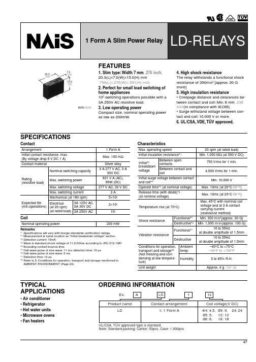
47mm inch20.3.799FEATURES1. Slim type: Width 7 mm .276 inch.20.3(L)×7.0(W)×15.0(H) mm .799(L)×.276(W)×.591(H) inch2. Perfect for small load switching of home appliances105 switching operations possible with a 3A 250V AC resistive load.3. Low operating powerCompact size, nominal operating power as low as 200mW.4. High shock resistanceThe relay withstands a functional shock resistance of 300m/s 2 [approx. 30 G more]5. High insulation resistance• Creepage distance and clearances be-tween contact and coil: Min. 6 mm .236 inch (In compliance with IEC65)• Surge withstand voltage between con-tact and coil: 10,000 V or more.6. UL/CSA, VDE, TÜV approved.SPECIFICATIONSContactCoilRemarks*Specifications will vary with foreign standards certification ratings.*1Measurement at same location as "Initial breakdown voltage" section.*2Detection current: 10mA*3Wave is standard shock voltage of ±1.2×50ms according to JEC-212-1981*4Excluding contact bounce time.*5Half-wave pulse of sine wave: 11 ms; detection time: 10 µs *6Half-wave pulse of sine wave: 6 ms *7Detection time: 10 µs*8Refer to 5. Conditions for operation, transport and storage mentioned in AMBIENT ENVIRONMENT (Page 24).CharacteristicsArrangement1 Form A Initial contact resistance, max. (By voltage drop 6 V DC 1 A)Max. 100 m ΩContact materialSilver alloy Rating(resistive load)Nominal switching capacity3 A 277 V AC, 3 A30V DC Max. switching power831 V A (AC), 90W (DC)Max. switching voltage 277 V AC, 30 V DCMax. switching current 3 A Expected life (min.operations)Mechanical (at 180 cpm)5×10⁶Electrical (at 20 cpm) (at rated load)3A 125V AC, 3A 30V DC2×1053A 250V AC105Nominal operating power 200 mWMax. operating speed20 cpm (at rated load)Initial insulation resistance*1Min. 1,000 M Ω (at 500 V DC)Initial*2 breakdownvoltageBetween opencontacts 750 Vrms for 1 min.Between contact and coil4,000 Vrms for 1 min.Initial surge voltage between contact and coil*3Min. 10,000 V Operate time*4 (at nominal voltage)Max. 10ms (at 20°C 68°F )Release time (with diode)*4 (at nominal voltage)Max. 10ms (at 20°C 68°F )Temperature rise (at 70°C)Max. 45°C with nominal coil voltage and at 3 A contact carrying current (resistance method)Shock resistanceFunctional*5Min. 300 m/s 2{approx. 30 G}Destructive*6Min. 1,000 m/s 2{approx. 100 G}Vibration resistanceFunctional*710 to 55Hzat double amplitude of 1.5mmDestructive10 to 55Hzat double amplitude of 1.5mmConditions for operation, transport and storage*8(Not freezing and con-densing at low tempera-ture)Ambient temp.–40°C to +70°C –40°F to +158°FHumidity 5 to 85% R.H.Unit weightApprox. 4 g .141 ozTYPICALAPPLICATIONS• Air conditioner • Refrigerator • Hot water units • Microwave ovens • Fan heatersORDERING INFORMATIONLD48TYPES AND COIL DATA (at 20 ° C68 ° F )Part No.Nominal voltage,V DCPick-up voltage,V DC (max.) (Initial)Drop-out voltage,V DC (min.) (Initial)Coil resistance, Ω ( ± 10%)Nominal operating currrent, mA ( ± 10%)Nominal operating power,mWMaximum allow-able voltage,V DC (at 20°C 68°F )ALD14H 4.5 3.380.2210144.6200 5.85ALD1055 3.750.2512540.0200 6.5ALD1066 4.50.318033.32007.8ALD1099 6.750.4540522.220011.7ALD1121290.672016.720015.6ALD1181813.50.91,62011.120023.4ALD12424181.22,8808.320031.2 DIMENSIONSmm inch1 to 3mm .039 to .118 inch : ± 0.2 ± .008Min. 3mm .118 inch : ± 0.3 ± .0124-(1). Operate timeSample: ALD112, 6 pcs.4-(2). Release time (without diode)Sample: ALD112, 6 pcs.4-(3). Release time (with diode)Sample: ALD112, 6 pcs.LD495-(1). Electrical life test(3 A 250 V AC, resistive load)Sample: ALD112, 6 pcs.Operating speed: 20 cpmAmbient temperature: room temperature circuit:Change of pick-up and drop-out voltageChange of contact resistanceFor Cautions for Use, see Relay Technical Information (Page 11 to 39).。
极空 B2A25S-RP 主动均衡继电器保护板 使用维护说明书
编号:JK-B2A25S-RP版本:1.2主动均衡继电器保护板(JK-B2A25S-RP)使用维护说明书成都极空科技有限公司产品保修条款产品名称:电池管理系统保修期限:壹年首先,感谢您购买成都极空科技有限公司推出的电池主动均衡器产品。
成都极空科技有限公司对由本公司出售的硬件产品和附件提供质量保修,保修期限如上所示。
在保修期内如果出现因质量原因而产生故障,公司在收到关于产品故障的通知并经查验核实后,有权选择维修或整套更换产品。
整套更换的产品可是新件或接近新件。
1.成都极空科技有限公司保证产品经过充分测试。
2.成都极空科技有限公司不保证在产品修理过程中产品可不中断地使用。
但公司应保证在合理的期限内修理好发生故障的产品。
3.产品保修期从产品发运之日或由成都极空科技有限公司开始安装之日开始计算。
如果因用户的进度安排或延后使公司产品在发运之日后的30天内仍未开始安装,产品保修期从发运之日后的第31天开始计算。
4.成都极空科技有限公司对任何下列情况而导致的产品故障和损坏不提供免费保修:(a)错误的使用或不适当的维护;(b)非成都极空科技有限公司提供的软件、附件、部件或其它物品;(c)未经许可的拆卸、修改和错误使用;(d)超过产品技术规格指明的范围使用;(e)不适当的运输、搬运和存贮;(f)其它非质量原因造成的故障或损坏(如地震、战争、交通事故等)。
在法律允许的范围内,上述保修条款是唯一明确的,同时没有任何其它的保修条款,不论是书面的或口头的。
明确表示拒绝承认任何隐含的保修条款和商业条款。
版权声明所有成都极空科技有限公司出售的产品或随同硬件产品出售的软件和文件,其版权属成都极空科技有限公司所有,成都极空科技有限公司保留产品和文件方面的所有版权。
用户对产品的购买并不表示用户在版权方面的任何许可。
未经成都极空科技有限公司书面许可的任何复制和出售均是被禁止的。
目次1概述 (4)2主要技术参数 (4)主要功能和技术指标 (4)使用环境条件 (2)3连接器及接口描述 (2)前面板连接器、LED灯位置描述 (2)前面板连接器、带灯开关定义描述 (2)产品外型 (4)尺寸 (4)分流器尺寸 (5)重量 (5)4安装方法及注意事项 (6)开箱检查及注意事项 (6)电池管理系统设备安装 (6)APP安装 (7)5使用与操作 (8)使用前的准备和检查 (8)电池管理系统上电工作 (8)APP操作说明 (8)6一般故障分析与排除 (14)7安全保护措施及注意事项 (15)8运输与贮存 (15)运输 (15)贮存 (15)附录“一键铁锂”、“一键三元”默认参数 (16)1概述JK-B2A25S-RP电池管理系统是为大容量串联锂电池组量身打造的电池管理系统。
图尔克RURCK继电器(24VDC _ 230VAC)

E.32.9.024.0040 24VDC 2CO 16A/250V 0.6A/110V P37 EE03 P41
E.32.8.230.0040 230VAC 2CO
E.33.9.024.0040 24VDC 3CO 16A/250V 0.6A/110V P37 EE03 P41
目录
继电器选型列表 ................................................................................4 常规技术信息 ....................................................................................5 A 系列 - 小型工业继电器 8 - 16 A....................................................19 A系列继电器插座和模块 .................................................................23 B 系列 - 普通继电器 7 - 10 A...........................................................24 B系列继电器插座和模块 .................................................................27 C 系列 - 小型电力继电器 12 A ........................................................28 C系列继电器插座和模块 .................................................................32 D 系列 - 普通继电器6 - 10 A ...........................................................33 D系列继电器插座和模块 .................................................................36 E 系列 - 电力继电器 16 A................................................................37 E系列继电器插座和模块 .................................................................41 线圈指示和EMC抑制模块 ...............................................................42
元则继电器的基本知识
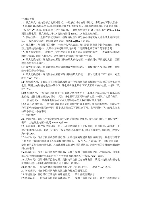
一.触点参数1.1 触点形式:继电器触点的配对形式,一组触点对时的配对形式,多组触点可依此类推1.2接触电阻:指接触的触点间电阻和与触点相连的簧片及引出端的导体电阻之和的总电阻。
一般以“m*”表示。
除非说明书中另有说明,一般触点负载小于1A的继电器用6Vd.c.,0.1A 测量接触电阻,触点负载大于1A的继电器用6Vd.c.,1A测量接触电阻。
1.3 接触压降:一般指在负载电路中,接触的触点间和与触点相连簧片及引出端上总的电压降。
一般以规定电流下的电压降值表示,如50mV(10A下测量)。
1.4 触点材料:触点使用的材料,一般以化学式表示,如元则继电器中银合金触点。
继电器上通常使用的材料,及其特性和适用环境请参见“元则继电器官网”的客服意见。
1.5 触点额定负载:一般指在一定的规定条件下触点能可靠切换的负载,一般以电压和电流的组合表示。
除非另有说明,说明书所列的负载一般为阻性负载。
1.6 最大切换电压:继电器触点所能切换的最大负载电压。
一般使用时不要超过此值,否则继电器的寿命会降低。
1.7 最大切换电流:继电器触点所能切换的最大负载电流。
一般使用时不要超过此值,否则继电器的寿命会降低。
1.8 最大切换功率:继电器触点所能可靠切换的最大负载,一般对交流用“VA”表示,对直流用“W”表示。
1.9 机械耐久性:指触点上不施加负载或施加不会导致继电器机械耐久性失效的监测电流和电压,线圈上施加额定电压的条件下,继电器在规定频率下可以正常切换的次数,一般以“次数”表示1.10 电耐久性:一般指继电器置于一定的规定环境条件下,在触点上施加规定负载比的规定负载,线圈上施加额定电压时,元则继电器可以正常切换的次数,一般以“次数”表示。
1.11 浪涌电流:一般指继电器触点可承受的特定种类负载的瞬时最大电流。
1.12 最小适用负载:一般指继电器触点能可靠切换的最小负载。
根据通断频率、环境条件和所要求的接触电阻等的不同,最小适用负载的可靠性也不同。
继电器样本
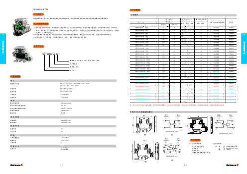
3 型号含义
4 技术参数
输入
额定输入电压
动作电压 返回电压 动作时间 返回时间
输出
最大切换电压 最大切 换电流(阻性负载) 最大 切 换 功 率(阻 性 负 载) 最高动作频率 触点材料
如需要其他规格可按用户要求单独订做继电耦合器返回电压返回时间输入动作电压额定输入电压动作时间最大切换电压最大切换功率阻性负载最高动作频率触点材料测试耐压使用寿命绕组触点机械寿命触头触点电气寿命dc12v24v48v60v110v220vac24v48v110v220v250vac30vdc2kva25kva4kva1800次小时银合金4技术参数输出最大切换电流阻性负载8a10a16a安装方式rtr35环境安装方式107105res72rx支架式设计序号工作环境温度1055储藏温度污染等级257022工作原理和结构继电耦合器用于各种自动保护和自动控制线路作为输出继电器或增加保护和控制回路触点的数量和容量
订货号
767068 767061 767077 767097 767101 767063 767102 767103 767107 767059 767108 767051 767047 767098 767062 767099 767100 767104 767064 767105 767106 767109 767057 767110 767053 767049 767086 767082 767072 767078 767080 767079 767076 767075 767052 767048 767054 767055 767085 767074 767081 767067
单片机系统开发_单片机硬件设计

复位电路
9 RST管脚
10u电解电容 4.7/10K电阻 微动按钮开关
单片机最小系统
最小系统
晶振电路
18 XTAL2管脚 19 XTAL1管脚
11.0592/12M晶振 20-33pf电容2个
单片机最小系统
最小系统
电源电路 DC12:Jack 5.5-2.1 Jack 3.5-1.1 USB:USB-A扁母口 USB-B方母口 SW6:6x6x6自锁紧开关 C2:去耦滤波电容 10—10uF R2+LED:电源指示灯
典型驱动电路
发光二极管LED
限流电阻值计算: 1、普通的发光二极管正偏压降红色为1.6V, 黄色为1.4V左右,蓝 白 为至少2.5V 。工作 电流5-10mA左右 2、超亮发光二极管主要有三种颜色,压降 都不相同,具体压降参考值如下: 红色发光二极管的压降为2.0--2.2V 黄色发光二极管的压降为1.8—2.0V 绿色发光二极管的压降为3.0—3.2V 正常发光时的额定电流约为20mA。 限流电阻计算如下:U为工作电压 R=(U-LED压降)/工作电流 Eg:R=(5V-1.6V)/10mA=340Ω (较亮) R =(5V-1.6V)/5mA=720Ω(较暗) 常用:470Ω,680Ω,1KΩ
典型驱动电路
继电器
常用:松乐5脚 5V DC 三只脚那端,左右是继电器 线圈,中间为动触点。 两只脚那端,左为动合触点, 右为动断触点(一个常开, 一个常闭。 )。
ULN2003驱动继电器
9013驱动 继电器
典型驱动电路
步进电机
常用:四项五线式 红线:VCC 四色:四项,依次接
Uln2003驱动步进电机
TTL转无线
港口高杆灯智能控制系统的设计与实现
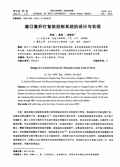
摘 要 : 计 了一种 基 于单 片机 的港 口高杆灯 智 能控制 系统.该 系统 能根 据港 口所在 地 的经纬度 设 和 日期 , 自动 计 算 当地每 天 日出 日落的时 间,从 而 实现 高杆灯 自动定 时开 关 ;应 用 GS 模 块 M 与单 片机通 信 ,通过短 信 实现对 高杆 灯的手 动控制 .实际运行证 明 了 系统稳 定且 可靠.
L Ya W EN I n, Ha o,CHANG Xi — u nH a
( . c o l f nomainE gn ei g Wu i nv ri , in me 2 0 0 C i a 1 S h o fr t n ie r , y iest Ja g n5 9 2 , h n ; oI o n U y
收 稿 日期 :2 1- 5 2 0 10 - 0 作 者 简介 :李 岩 ( 9 6 ) 男 , 山 东济 南人 ,在 读硕 士 生 。研 究 方 向为 模 式识 别及 智 能控 制 1 8一 。
第2 6卷
第1 期
李岩等 :港 口高杆灯智能控制 系统 的设 计与实现
5 9
1 系统 构 成 及原 理
的转换 ,同时增加 T vS管 对 L DO的保 护.
U3 N V 2 4 C 62
Ii 厂— v
rP 1 3. ; IO : l
n
专v. o u
Cl l
松下继电器hj
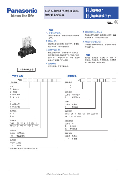
订购产品号 AHJ812430 AHJ812630 AHJ812530 AHJ812830
订购产品号 AHJ81240630 AHJ81260630 AHJ81250630 AHJ81280630
DC 12V DC 24V DC 48V DC100/110V AC 12V AC 24V AC 48V AC100/110V AC110/120V AC200/220V AC220/240V
HJ2 L DC 12V HJ2 L DC 24V HJ2 L DC 48V HJ2 L DC 110V HJ2 L AC 12V HJ2 L AC 24V HJ2 L AC 48V HJ2 L AC 100V HJ2 L AC 120V HJ2 L AC 200V HJ2 L AC 220/240V
3. 插入型(带二极管)
线圈电压
2c 型号
DC 12V DC 24V DC 48V DC100/110V
HJ2 DC 12V D 6 HJ2 DC 24V D 6 HJ2 DC 48V D 6 HJ2 DC 110V D 6
4. 插入型(带二极管·带LED显示)
线圈电压
2c 型号
DC 12V DC 24V DC 48V DC100/110V
6. 带夹手保护型功能。
为不使手接触到端子部分,备有带夹手保护 型的端子台。
用途
控制盘、电源设备、成型机、加工机械、焊 接设备、农业机械、商务用机器、自动贩卖 机、通信设备、娱乐机器等。
型号体系
HJ
触点构成
c
c
动作显示
无标示 无LED显示
八角继电器产品承认书-元则电器
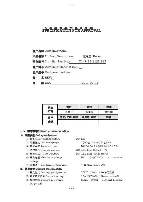
八 角 继 电 器 产 品 承 认 书SPECIFICATION FOR APPROVAL一、基本特性Basic characteristics1、 线圈参数Coil specification(1) 额定电压Nominal voltage DC 12V (2) 线圈阻抗Coil resistance 360Ω±10% (at 23±5℃) (3) 额定电流Rated current DC 33.3mA ±10% (at 23±5℃) (4) 动作电压Operate voltage DC 9.0V Max ((at 23±5℃) (5) 释放电压Release voltage DC 0.6V Min ((at 23±5℃) (6) 最大电压Maximum voltageDC 15.6V(130% of nominal voltage)(7) 线圈温升Coil temperature rise 45K Max (Coil:12V)2、 触点参数Contact Specification(1) 触点型式Contact configuration SPDT (1 Form C)—单刀双掷 (2) 触点额定负载Contact rating 16A 250VAC ; (Resistive load) (3) 接触电阻Contact resistanceInitial (初始值) 100 m Ω Max (AtDC6V 1A)客户名称Customer name : 产品名称Product Description : 继电器 Relay 供方型号Supplier Part No.: Y14F-SS-112L-115 客户料号Customer Material Code : 客户型号Customer Part No.: 版 本REV : 日 期Date : 2017-03-01(4)动作时间Operate time 10ms Max(5)释放时间Release time 8ms Max(6)最大动作频率Maximum operating Mechanically 18000 cycle/h(机械)frequency Electrically 600 cycle/h(电气)(7) 触点温升Contact temperature rise 50K Max (Contact:16A)3、通用参数General Specification(1) 绝缘阻抗Insulation resistance 1000MΩMin (at DC500V)(2) 电气强度Dielectric strength开路触点间between open contacts 1000VAC,50/60 HZ for 1Minute线圈与触点间between contacts and coil 5000VAC,50/60 HZ for 1 Minute(3) 环境温度Ambient temperature -40℃~+105℃(Not freezing and condensing at lowtemperature)(4) 相对湿度Relative Humidity 45% to 85% RH(5) 电气寿命Electrical life 100,000 Operations Min (at 16A250VAC)(6) 机械寿命Mechanical life 10,000,000 operations Min4、体系、安规认证和环保Quality System、Safety Certification and RoHS(REACH)(1) UL certified File NO. E341498;16A 250VAC(2) TUV certified File No. R5019847916A 240VAC(3) CQC certified File No. CQC1100205615216A 250VAC(4) ISO9001:2008 certified File No. 05311Q22581R0S(5) RoHS and REACH Compliant二、环境参数Environmental Characteristics1、抗振动性Vibration resistance1.1 误动作Error operation在X、Y、Z轴三个方向施加双振幅为1.5mm,频率为10-55HZ的振动,时间5分钟,误动作时间不超过1ms。