AJZ- 双切断阀说明书
冷冻设备安全操作指南:冷冻专业设备手动关断阀门操作指南说明书

SERVICE AND MAINTENANCEAll systems require maintenance and service. The personnel doing the work must be qualified and completely familiar with the system they are working on or all other precautions will be meaningless.Caution: Do not attempt to work on any part of a refrigeration system without having help nearby and observing. Use safety glasses or a safety face shield to protect the eyes. Protective equipment should be readily available and all personnel involved should be thoroughly trained in its use. Personnel should be especially protected against falling because they may be startled by escaping refrigerant. Always make sure that there is a way out and that everyone can leave the area fast. When seal caps cover manual opening or adjusting stems, the caps must be removed with caution because liquid refrigerant could accumulate under such a cap. Avoid contact with any liquid refrigerant.PUMP OUTFor the protection of personnel, product, and plant, all refrigerant possible must be removed from a valve or any other component of the system, before any refrigerant retaining part is loosened. Before opening a valve, make sure all refrigerant liquid has been removed. In particular, beware of strainers and other sections of piping which may trap liquid refrigerant which will require a considerable length of time to remove. Pump out as much refrigerant as possible before discharging remaining refrigerant in a properly protected manner. During pump out, make sure control valves are opened manually to avoid trapping refrigerant .All type RSF and RSW Strainers are provided with 3/8” FPT connection to assist in pump out.At times, it may be necessary to discharge some small amount of refrigerant from the isolated section. When this becomes necessary, certain precautions must be observed. Make sure control of discharge rate can be easily maintained and that a quick shut-off is available.Refrigerant should be discharged into and disposed of in a proper container accepted by applicable safety codes and standards. Discharge of refrigerant to atmosphere should be avoided. Never discharge any refrigerant into an area without sufficient ventilation, or into an area where open flame or electrical spark is present. Any oil in the refrigerant may cause a mist that could cause a fire or explosion.Halocarbon refrigerant should not be discharged into areas where open flame is present, since toxic gases may form. Ammonia should not be discharged into occupied areas, or areas containing product affected by ammonia. In the case of ammonia, discharge any vapor left into a container of cold water, making sure that the discharge hose remains submerged at all times. (Be sure that no pressure reversals can occur that may pull water into the system.) Water may have to be changed to absorb all the ammonia; about one gallon of fresh water is needed for one pound of ammonia.To prevent ingress of excessive air and moisture into a system, avoid opening the system when it is under vacuum.DISASSEMBLYBe sure that any person working on a valve is familiar with its construction and operation by referring to the proper bulletin. Make sure the pressure in the system to be opened is reduced to, and remains, at atmospheric pressure before opening the valve. A pressure gauge should be connected to the section of the system to be evacuated.RE-ASSEMBLYBe sure all parts are clean and free of moisture before re-assembly. Damaged parts and gaskets should be replaced. It is advisable to purge the section of air before opening it to the rest of the system. When opening hand valves, always open the valve to the inlet of the control valve first; this will avoid backflow and possible damage to the strainer if one is used.GENERAL SPECIFICATIONSRefrigerating Specialties refrigerant containing valves and strainers are designed for a Maximum Rated Pressure of 27.6 bar (400 psig) except where shown otherwise on the nameplate. They are suitable for use under most temperature conditions encountered in refrigeration systems. Maximum and minimum fluid temperatures for each valve are published in R/S Condensed Catalog CC I I c. If either fluid or ambient temperature is below a valve’s rated minimum, consult the factory. In addition, should fluid temperature exceed the rated maximum or ambient temperatures exceed 125° F., please consult factory.The valves are designed to operate with ammonia and/or halocarbon refrigerants. Unless authorized by the factory, Refrigerating Specialties valves should not be used for refrigerants or fluids not mentioned on the nameplate or in the pertinent bulletin.。
Parker Autoclave Engineers双阻流断阀门说明书

Parker Autoclave Engineers Double Block & Bleed valve is a two-stem ball valve with needle style vent valve providing economical and reliable isolation in critical areas superior in comparison to a standard, single valve. This valve is de-signed for use where critical isolation is needed to ensure that leakage does not occur. Our 3/8" and 5/8" Double Block & Bleed valves are designed to save space and weight while capable of pressures to 15,000 psi (1034 bar). These ball valves can also be modified to incorporate the use of special materials, optional seals with and capability for high tem-perature applications to 500°F (260°C).Double Block & Bleed Ball Valve Features:• One-piece, trunnion mounted style, stem design eliminates shear failure and reduces the effects of side loading found in two piece designs• Re-torqueable seat glands for longer seat life• Carbon filled PEEK seats offer excellent resistance to chemicals, heat, and wear/abrasion • Vee-Stem Needle Vent Valve with PTFE Packing • Full-port flow path minimizes pressure drop• Manufactured using UNS S31600 316 cold worked Stainless Steel• Low friction pressure assisted graphite filled PTFE stem seal increases cycle life and reduces operating torque • FKM o-rings for operation from 0° to 400°F (-18 to 204°C)Traceability is ensured by use of heat and purchase order codes etched on valve body that also includes model number, MAWP rating, and material type references. Parker Autoclave Engineers’ valves are complemented by a complete lineof Medium Pressure Cone & Thread, or NPT fittings, check valves, relief valves, and line filters.Ball ValveDouble Block & Bleed, 1/4 Turn3/8" & 5/8" Bore to 15,000 psi (1034 bar)6DB and 10DB Series6DB Series:.323" (8.20mm) Orifice - Pressures to 15,000 psi (1034 bar)Pressure Temperature RatingsTemperature ºF (ºC)PressurePSIG(Bar)100(38)200(93)300(150)400(204)500(260)(-18)5000(345)10000(690)15000(1034)1/2" LP ConnectionMP & NPT Connection6DB Series Ball Valve SeriesPressure Ratings are determined by the end connections chosen, see chart.Maximum Temperature rating is determined by the o-ring material.NPT connections are limited to 400°F max due to PTFE Sealant.** Special materials often have reduced MAWP ratings, see Technical brochure for assistance3Ball Valves: 6DB & 10DB Double Block and Bleed Series 02-1258SE 0821Ordering Guide:For complete information on available end connections and material options, see below. 6DB ball valves are furnished complete with tube or pipe connections. Standard valve has FKM o-rings [0-400ºF (204ºC) maximum].Basic Repair Kits:6DB Double Block & Bleed Valves are not repairable in field and must be returned to authorized repair center or factory location.4Ball Valves: 6DB & 10DB Double Block and Bleed Series 02-1258SE 08216DB Series 3/8" Bore Ball Valve Dimensions:Panel Mounting Dimensions:Material of Construction:* Centerline location of vent outlet port6DB Series 3/8" Bore Ball Valve Material:5Ball Valves: 6DB & 10DB Double Block and Bleed Series 02-1258SE 082110DB Series:.623" (15.82mm) Orifice- Pressures to 15,000 psi (1034 bar)Pressure Temperature RatingsTemperature ºF (ºC)PressurePSIG(Bar)100(38)200(93)300(150)400(204)500(260)(-18)5000(345)10000(690)15000(1034)NPT ConnectionSF Connection10DB Series Ball Valve SeriesPressure Ratings are determined by the end connections chosen, see chart.Maximum Temperature rating is determined by the o-ring material.NPT connections are limited to 400°F max due to PTFE Sealant.** Special materials often have reduced MAWP ratings, see Technical brochure for assistance Series M10DB Vent Valve Option Shown7Ball Valves: 6DB & 10DB Double Block and Bleed Series 02-1258SE 0821Ordering Guide:For complete information on available end connections and material options, see below. 10DB Series ball valves are furnished complete with tube or pipe connections. Standard valve has FKM o-rings [0-400ºF (204ºC) maximum].Basic Repair Kits:10DB Double Block & Bleed Valves are not repairable in field and must be returned to authorized repair cen-ter or factory location.810DB Series 5/8" Bore Ball Valve Dimensions:Panel Mounting Dimensions:Material of Construction:* Centerline location of vent outlet port10DB Series 5/8" Bore Ball Valve Material:9 Ball Valves: 6DB & 10DB Double Block and Bleed Series 02-1258SE 082110Ball Valves: 6DB & 10DB Double Block and Bleed Series 02-1258SE 0821NOTES:High PressureValves • Fittings • Tubingto 150,000 psi.Reactors • Vessels InstrumentationAir Driven, High Flow, High Pressure Liquid PumpsParker’s Motion & Control TechnologiesAt Parker, we’re guided by a relentless drive to help our customers become more productive and achieve higher levels of profitability by engineeringthe best systems for their requirements. It means looking at customer applications from many angles to find new ways to create value. Whateverthe motion and control technology need, Parker has the experience, breadth of product and global reach to consistently deliver. No company knows more about motion and control technology than Parker. For further information call 1-800-C-Parker.11Ball Valves: 6DB & 10DB Double Block and Bleed Series 02-1258SE 0821Ball Valves: 6DB & 10DB Double Block and Bleed Series 02-1258SE 0821! CAUTION !Do not mix or interchange component parts or tubing with those of other manufacturers. Doing so is unsafe and will void warranty.Parker Autoclave Engineers Valves, Fittings, and Tools are not designed to interface with common commercial instrument tubing and are designed to only connect with tubing manufactured toParker Autoclave Engineers AES specifications. Failure to do so is unsafe and will void warranty.Offer of SaleThe items described in this document are available for sale by Parker Hannifin Corporation, its subsidiaries or its authorized distributors. Any sale contract entered by Parker will begoverned by the provisions stated in Parker's standard terms and conditions of sale (copy available upon request).©2021 Parker Hannifin Corporation | Autoclave Engineers is a registered trademark of the Parker Hannifin Corporation Literature #: 02-1258SE August 2021Parker WorldwideISO-9001 CertifiedInstrumentation Products Division Autoclave Engineers Operation 8325 Hessinger Drive Erie, PA 16509-4679Tel: 814 860 5700Fax: 814 860 /ipdInstrumentation Products Division Division Headquarters 1005 A Cleaner WayHuntsville, AL 35805 USA Tel: 256 881 2040Fax: 256 881 5072WARNINGFAILURE, IMPROPER SELECTION OR IMPROPER USE OF THE PRODUCTS AND/OR SYSTEMS DESCRIBED HEREIN OR RELATED ITEMS CAN CAUSE DEATH,PERSONAL INJURY AND PROPERTY DAMAGE.This document and other information from Parker Hannifin Corporation, its subsidiaries and authorized distributors provide product and/or system options for further investigation by users having technical expertise. It is important that you analyze all aspects of your application and review the information concerning the product or system in the current product catalog. Due to the variety of operating conditions and applications for these products or systems, the user, through its own analysis and testing, is solely responsible for making the final selection of the products and systems and assuring that all performance, safety and warning requirements of the application are met. The prod-ucts described herein, including without limitation, product features, specifications, designs, availability and pricing, are subject to change by Parker Hannifin Corporation and its subsidiaries at any time without notice.North AmericaUSA – Corporate, Cleveland, OH Tel: +1 256 896 3000USA – IPD, Huntsville, AL Tel: +1 256 881 2040*****************USA – IPD, (Autoclave), Erie, PA Tel: +1 814 860 5700*******************CA – Canada, Grimsby, Ontario Tel +1 905-945-2274*********************South AmericaAR – Argentina, Buenos Aires Tel: +54 3327 44 4129 ******************BR – Brazil, Diadema, SP Diadema, SPTel: +55 11 4360 6700******************CL – Chile, Santiago Tel: +56 (0) 2 2303 9640******************MX – Mexico, Toluca Tel: +52 722 275 4200*******************Asia PacificAU – Australia, Dandenong Tel: +61 (0)2 9842 5150******************************CN – China, Shanghai Tel: +86 21 2899 5000*****************************HK – Hong Kong Tel: +852 2428 8008IN – India, MumbaiTel: +91 22 6513 7081-85ID – Indonesia, Tangerang Tel: +62 2977 7900********************JP – Japan, Tokyo Tel: +(81) 3 6365 4020******************KR – South Korea, Seoul Tel: +82 2 559 0400*******************MY – Malaysia, Selangor Tel: +603 784 90 800*******************SG – Singapore,Tel: +65 6887 6300*******************TH – Thailand, Bangkok Tel: +66 2 186 7000*********************TW – Taiwan, Taipei Tel: +886 2 2298 8987*************************VN – Vietnam, Hochi Minh City Tel: +848 382 508 56**********************Europe, Middle East, AfricaAE – UAE, Dubai Tel: +971 4 812 7100********************AT – Austria, Wiener Neustadt Tel: +43 (0)2622 23501-0*************************AT – Eastern Europe, Wiener Neustadt Tel: +43 (0)2622 23501 900****************************AZ – Azerbaijan, Baku Tel: +994 50 2233 458****************************BE/LU – Belgium, Nivelles Tel: +32 (0)67 280 900*************************BG – Bulgaria, Sofia Tel: +359 2 980 1344**************************BY – Belarus, Minsk Tel: +48 (0)22 573 24 00*************************CH – Switzerland, Etoy Tel: +41 (0) 21 821 87 00*****************************CZ – Czech Republic, Klecany Tel: +420 284 083 111*******************************DE – Germany, Kaarst Tel: +49 (0)2131 4016 0*************************DK – Denmark, Ballerup Tel: +45 43 56 04 00*************************ES – Spain, Madrid Tel: +34 902 33 00 01***********************FI – Finland, VantaaTel: +358 (0)20 753 2500*************************FR – France, Contamine s/Arve Tel: +33 (0)4 50 25 80 25************************GR – Greece, Athens Tel: +30 210 933 6450************************HU – Hungary, Budapest Tel: +36 223 885 470*************************IE – Ireland, DublinTel: +353 (0)1 466 6370*************************IT – Italy, Corsico (Ml)Tel: +39 02 45 19 21***********************KZ – Kazakhstan, Almaty Tel: +7 7273 561 000****************************NL – The Netherlands, Oldenzaal Tel: +31 (0)541 585 000********************NO – Norway, Stavanger Tel: +47 66 75 34 00************************PL – Poland, Warsaw Tel: +48 (0)22 573 24 00************************PT – Portugal, Leca da Palmeira Tel: +351 22 999 7360**************************RO – Romania, Bucharest Tel: +40 21 252 1382*************************RU – Russia, Moscow Tel: +7 495 645-2156************************SE – Sweden, Spånga Tel: +46 (0)8 59 79 50 00************************SK – Slovakia, Banská Bystrica Tel: +421 484 162 252**************************SL – Slovenia, Novo Mesto Tel: +386 7 337 6650**************************TR – Turkey, Istanbul Tel: +90 216 4997081************************UA – Ukraine, KievTel: +48 (0)22 573 24 00*************************UK – United Kingdom, Warwick Tel: +44 (0)1926 317 878********************ZA – South Africa, Kempton Park Tel: +27 (0)11 961 0700*****************************。
切断阀使用手册-电子版

二)指挥器
警告
在安装、操作或维修SSV3000系列切断阀之前,必须先完整的阅读本
使用手册。与本切断阀的安全安装和操作规程要求不符合的操作都可能会导
致严重的伤亡事故。
一、简介
SSV3000系列切断阀是安装在调压站或气体分输管线的自动进行切断的一种安
全装置。当下游的压力达到切断阀的切断设定压力时,切断阀能够快速切断供气。
SSV3000是一种套筒式设计,因此当对切断阀进行复位时,不需要外部的旁通
设备。切断阀的复位只能通过人工手动进行。
同时可选配的附件:
-远程电子切断
-信号远程
二、应用范围
SSV3000切断阀适用于长管道
气体传输的接收站,及广泛应用于多
级燃气供应管网,地区燃气供应,大
中型公福用户、工业用户、加热装置
等要求压力控制精确、反应速度快的
SSV3000系列切断阀
使用手册
目
录
一、
二、
三、
四、
五、
六、
七、
八、
九、
十、
简介
产品应用
产品特点
技术特性
切断阀工作原理
执行机构及指挥器
超压切断压力范围和指挥器弹簧参数
安装
启动
一)切断阀切断压力设定步骤
二)切断阀复位步骤
故障分析及维护检查
一)常见故障分析
二)定期检查
十一、维修保养
十二、零件及备品备件示意说明
燃气供应场合,工业及区域级燃气供
应站,供暖设备厂等工业用户。
适用介质:天然气、城市煤气、
液化石油气、空气、氮气等非腐蚀性
气体。
三、产品特点
◇
截止阀使用说明书

截止阀安装使用说明书1 概述截止阀是用来关闭、开启和节流管道介质,截止阀可以完全阻断流体,在阀杆作用力下形成良好密封;Y型截止阀根据阀门的总体设计安装要求确定;截止止回阀在打开状态下可作为控制管道介质单向流动的元件,当介质顺流时由管线自身压力的作用开启阀门,当介质倒流时依靠阀瓣自身重量和介质回流的压力作用在阀瓣背部,使阀瓣与阀座形成密封,达到止回截流的目的。
在10%的开启位置至全开时,采用节流型阀瓣的截止阀对管线的流量调节是有效的。
该类阀门顺时针旋转手轮,阀瓣下降,直到完全将通道切断,阀门关闭。
逆时针旋转手轮,阀瓣上升,直到碰到阻挡,阀门打开。
对于电动装置阀门,在断电等紧急情况下,可以使用备用手轮打开和关闭阀门。
注意!在不超过10%开启状态连续节流会对阀瓣和阀座引起剧烈振动、噪音、磨损和损坏。
2 阀门的储存2.1 发运准备阀门的包装应能防止阀门在运输过程和储存时不发生任何损坏。
并应注意以下几点:1) 包装时,阀瓣应处于关闭状态。
2) 阀门法兰密封面/焊接坡口/螺纹端应涂合适的防护油脂(不锈钢材质除外),阀门两端应可靠地固接木质、木纤维或塑料端盖以防护连接端面和阀门内部。
3) 电动装置阀门包装时须小心地安全固定,以确保电动装置不会损坏并不至于穿破木箱/板条箱。
4) 包装型式应在订单中明确规定,以便安全地运输至目的地和确保安装前的保存。
2.2 吊运要求A. 包装完好的阀门板条箱:用叉车进行装卸。
木箱:在木箱的重心位置处设置装吊点进行装卸。
B. 已开箱的阀门1) 这些阀门的吊运要采取合适的手段和措施如应用货盘进行装卸,注意应避免加工面受到损坏。
2) 对大尺寸阀门,在吊运阀门时可用皮带或链条绕过阀体的颈部吊起,并应保持平衡以防止意外坠落或在吊运过程中松动。
警告!1) 吊运设备(如皮带、链条等)的尺寸须合适,以便足够承受阀门的重量。
2) 吊运须由有资格人员操作。
3) 吊运时应避免通过人员的上空或任何当意外坠落时可能导致损害的区域。
紧急切断阀使用说明书

艰苦练习才能得到成功英语作文## English Answer:The Path to Success Lies in Rigorous Practice.In the realm of human endeavor, success rarely manifests itself as a fortuitous happenstance. It is a tapestry meticulously woven with threads of dedication, perseverance, and unwavering determination. At the heart of this intricate process lies a fundamental truth: true success is inextricably intertwined with the arduous journey of practice.Like a master sculptor chiseling away at a block of marble, uncovering the beauty hidden within, practice relentlessly shapes our minds and skills, graduallyrefining our abilities until they reach their full potential. With each repetition, we chip away at the imperfections, honing our technique, expanding our knowledge, and strengthening our resolve.The benefits of practice are undeniable. It enhances our focus, enabling us to concentrate more effectively on the task at hand. It improves our memory, allowing us to retain information more efficiently and recall it with greater accuracy. And most importantly, it cultivates resilience, empowering us to overcome obstacles and setbacks with increased tenacity.countless examples throughout history attest to the transformative power of practice. From the virtuosoviolinist whose fingers dance effortlessly across the strings to the brilliant scientist who deciphers complex equations with ease, these individuals have achieved unparalleled mastery in their respective fields through years of tireless practice.As the saying goes, "Practice makes perfect." However, it is essential to recognize that perfection is an elusive ideal. True mastery lies not in achieving an unattainable standard, but in relentlessly pursuing excellence, striving for continuous improvement, and never settling formediocrity.The journey of practice is not always an easy one. It demands sacrifice, discipline, and an unwavering belief in oneself. There will be moments of frustration and self-doubt, but it is precisely during these times that we must dig deep and summon our inner strength. Remember, setbacks are not failures but opportunities for growth and learning.Ultimately, the rewards of practice far outweigh its challenges. It empowers us to transcend our perceived limitations, to achieve our goals, and to live lives filled with purpose and fulfillment. So let us embrace the arduous path of practice, knowing that with unwavering dedication and relentless effort, we can unlock the potential thatlies within us and forge a path to true success.### Chinese Answer:艰苦练习才能得到成功。
燃气切断阀使用说明

燃气切断阀使用说明1. 引言燃气切断阀是一种用于安全关闭家庭或工业燃气供应的装置。
本使用说明将详细介绍燃气切断阀的使用方法、注意事项以及常见问题解决方案。
2. 燃气切断阀的种类和结构燃气切断阀主要分为手动切断阀和自动切断阀两种类型。
手动切断阀需要人工操控,而自动切断阀则会在检测到燃气泄露等异常情况时自动关闭。
燃气切断阀的结构包括以下几个部分: - 切断阀体:由阀体和连接口组成,通常采用耐腐蚀材料制造,以确保阀门的可靠性和耐用性。
- 传动机构:负责将操作杆、电机或电磁阀等动力源的动力传递到阀门上,以控制燃气的通断。
- 操作手柄:用于手动操作切断阀,通常有开关和关闭两个位置。
- 控制装置:自动切断阀上的控制器,用于监测燃气泄漏、温度异常等情况,并控制阀门的开关。
3. 燃气切断阀的安装在安装燃气切断阀之前,请务必确保你具备以下条件和工具: - 相关的安装许可证和资质证明。
- 符合相关安全标准的阀门和配件。
- 适用于燃气管道的工具包,如扳手、管道胶带等。
安装步骤如下: 1. 关闭燃气供应,确保燃气管道中没有残余气体。
2. 根据切断阀的型号和规格选择合适的安装位置。
3. 使用扳手等工具,将切断阀与燃气管道连接。
4. 确保连接口处无渗漏,紧固好螺纹。
5. 根据需要,连接切断阀的控制装置(若为自动切断阀)。
4. 燃气切断阀的使用方法4.1 手动切断阀的使用方法手动切断阀的使用方法较为简单,按照以下步骤进行操作: 1. 打开操作手柄,将其置于开启位置。
2. 燃气开始流动,确保没有任何异常情况。
3. 当需要切断燃气供应时,将操作手柄逆时针拧紧,切断阀会分离燃气管道,停止燃气供应。
4. 如需恢复燃气供应,将操作手柄顺时针旋转至开启位置。
4.2 自动切断阀的使用方法自动切断阀通过控制装置实现自动监测与切断,操作相对复杂一些: 1. 确保控制装置工作正常,且连接正确。
2. 打开控制装置,等待系统自检完成。
截止阀使用说明书

截止阀操作和维护手册1. 总则该系列的阀门,在管线系统中用于关闭或开启管线,保持系统正常运行。
2. 产品描述2.1 该系列的阀门为带有法兰端、螺纹端、对焊端、承插焊端,通过手轮驱动截止阀。
阀杆以垂直的方向移动。
当顺时针旋转手轮时,阀瓣落下来关闭管线,当逆时针旋转手轮时,阀瓣上升,开启管线。
2.2 该系列的阀门是依据ASME B 16.34 和API 600 、API 602 标准规范进行设计的。
2.3 结构简图见图1、图2、图3:图图2 图32.4 主要部件名称和材料:零件名称材料阀体、阀盖ASTM A216 WCB、ASTM A352 LCB、ASTM A217 WC6、ASTM A351 CF3M、ASTM A351 CF8、ASTM A105、ASTM A182 F304阀瓣ASTM A216 WCB+13Cr、ASTM A216 WCB+STL、ASTM A352 LCB+13Cr、ASTM A217 WC6+13Cr 、ASTM A351 CF3M+316SS 、ASTMA351 CF3M+STL、ASTMA351 CF8+304SS、ASTMA351 CF8+STL、ASTM A105+13Cr、ASTM A182 F304SS阀座ASTM A105+13Cr、ASTM A105+STL、ASTM A350 LF2+13Cr、ASTM A182 F 304SS、ASTM A182 F316+STL、ASTM A182 F6a 阀杆ASTM A182 F6a、ASTM A182 F304SS、ASTM A182 F316SS、ASTM A182 F316LSS填料编织石墨环和柔性石墨螺柱/螺母ASTM A193 B7/ASTM A194 2H、ASTM L320 L7/ ASTM A194 4、ASTM A193 B16/ASTM A194 4 、ASTM A193 B8/ ASTM A194 8 ASTM A193 B8M/ ASTM A194 8M3. 存贮、维护、安装和操作3.1 存贮、维护3.1.1 阀门应被存贮在室内干燥和通风处。
切断阀作业指导书
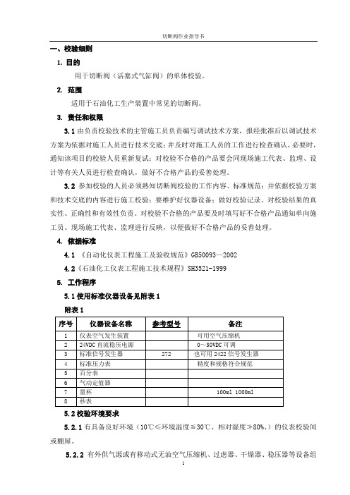
一、校验细则1. 目的用于切断阀(活塞式气缸阀)的单体校验。
2. 范围适用于石油化工生产装置中常见的切断阀。
3. 责任和权限3.1由负责校验技术的主管施工员负责编写调试技术方案,报经批准后以调试技术方案为依据对施工人员进行技术交底;并及时对施工人员的工作进行检查确认,必要时,通知该项目的校验人员重新复试;对校验不合格的产品要会同现场施工代表、监理、设计等有关人员进行检查确认,做好不合格产品的妥善处理。
3.2 参加校验的人员必须熟知切断阀校验的工作内容、标准规范;并依据校验方案和技术交底的内容进行施工校验;要维护好仪器设备;做好校验记录。
对校验结果的真实性、正确性和有效性负责。
对校验不合格的产品要及时填写好不合格产品通知单向施工员、现场施工代表、监理进行反映,以便做好不合格产品的妥善处理。
4. 依据标准4.1《自动化仪表工程施工及验收规范》GB50093—20024.2《石油化工仪表工程施工技术规程》SH3521-19995. 工作程序5.1使用标准仪器设备见附表1附表15.2校验环境要求5.2.1有具备良好环境(10℃≤环境温度≦30℃、相对湿度≯80%、)的仪表校验间或棚屋。
5.2.2有外供气源或有移动式无油空气压缩机、过虑器、干燥器、稳压器等设备组成的仪表空气发生装置提供气源。
要求气源应清洁干燥,气源压力应稳定,波动值允许误差小于额定值的±10%。
5.2.3强度、泄漏量试验所用介质为5~10℃(空气或氮气)或清洁水。
5.2.4所用电源电压波动幅度不超过±10%。
5.2.5所用标准仪器应具备有效的检定合格证书,其基本误差的绝对值不宜超过被校表基本误差的绝对值的1/3。
5.3 校验前的准备工作5.3.1由负责校验技术的主管施工员对参加校验的施工人员进行技术方案交底。
5.3.2参加校验的施工人员详细了解切断阀规格表的内容和使用说明书,掌握切断阀调试的校验方法,明确切断阀校验的特殊要求和规定。
紧急切断阀安装使用说明书

气动低温紧急切断阀使用说明书安全严禁用于超过公称压力,否则有可能发生破损事故。
气缸充入气压0.4~0.7 Mpa,严禁用于超过0.7 Mpa,否则有可能发生破损事故。
严禁随意更换未经认可的密封装置。
工作原理气缸充入指定压力时,活塞上升带动阀杆开启阀门,关闭时释放气缸内气体, 活塞在弹簧的作用下带动阀杆与阀瓣向下运动,密封件压紧阀座,阀门关闭;气动操作时,当阀门的周围环境温度达到易熔金属熔化温度时(用于低温槽车、低温罐式集装箱的紧急切断阀易熔塞在75℃±5℃应熔化),易熔塞内部的易熔金属就会熔化,汽缸内的工作压力会自动排放,活塞在弹簧的作用下带动阀杆与阀瓣向下运动,密封件压紧阀座,阀门关闭;旋转顶部的手轮带动阀杆与阀瓣向上运动,可手动开启阀门。
安装先按阀体上的标识确定输出输入方向。
在焊接前必须彻底清扫管道内的异物,反复确认管道内有无异物,然后再安装焊接。
开袋后也可以直接就焊。
(为防万一还是先确认焊接开口处的清洁状态为好,如需清扫,请先清扫后再焊接。
)在进行焊接之前,请根据阀的材质、焊条的材质、电流、姿势等决定适当的条件后再作业。
在焊接时不要使阀体过分受热,以防阀体变形。
焊接时要使阀门处于开启状态,并用清洁的保护气体进行保护焊接。
要按照阀体侧面所表示的流向进行配管安装。
安装在液相管道上的阀门原则上要垂直安装。
不得不带角度时在与垂直方向45度的范围内安装。
严禁在45度的范围以上或横向、朝下安装,否则将会因结霜(冰)造成阀门无法正常工作。
控制气源及管路安装控制气源应是清洁干燥空气、氮气或罐柜自身的气相,气源压力为0.4~0.7 Mpa,否则可能会影响阀门正常工作;推荐使用独立专供紧急切断阀的气源装置,如压缩空气、氮气瓶;如使用罐柜自身的气相,应在三通球阀或电磁阀的上游安装一个止回阀,当气缸动作开启阀门后,保持气缸内压力不变;控制气管路元件为一个调压阀、(止回阀)、三通球阀或二位三通电磁阀(隔暴型)及一个压力表,如气源为易燃易爆气体则放空管应接入储罐管路系统集中排放。
双关双断旋塞阀 说明书.pdf

High Integrity Shutoff When the valve is closed the elastomeric seal rings are forced against the seats each side of the valve body. The force is directed at a perpendicular direction by the wedging action of the slips. The elastomer seals on the slips, are secured within a machined grove by a bonding agent. As for being fire safe, the outside surface around the seals (on the slips) is a finished surface of metal, that is forced against the metal body seat. This results in both an elastomeric and metal to metal drop tight seal.
切断阀使用手册-电子版
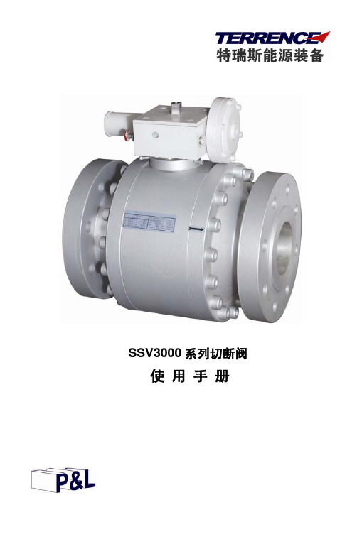
/
32-60
/
40-100
/
60-150
/
130-245
/
220-350
/
/
0.65-1.27
/
1.25-2.6
/
2.3-4.0
/
AE100+ SAV120TR
(mbar) 50-100 70-150 110-250 230-420 390-600
/ / / /
表 5 弹簧直接作用式执行机构(高压):
/
超压切断压力范围 AE100+ DAV30 (bar) 4.0-7.0 6.0-11.0 9.0-16.0 15.0-25.0 24.0-36.0 35.0-45.0
AE100+ DAV15 (bar) 16.0-27.0 26.0-42.0 35.0-62.0 58.0-85.0
/ /
表 6 指挥器结合弹簧直接作用式执行机构:
表 3 切断阀超低压的执行机构和指挥器
执行机构类型
指挥器型号
最大允许压力 PS
PAL81
100
AE100-PL
PAL81/HP
100
表 4 切断阀超高压的执行机构和指挥器
双向切断阀门参数与特点说明书

Features and Benefits• Two way shut-off valves for the control air, inert gas, water, oil and other gases/liquids compatible with the sealing material used • Valves do not require a minimum operating pressure• All products are covered by Pressure Equipment Directive 2014/68/EU and are suitable for group 1 and 2 fluids• The solenoid valves satisfy all relevant EU directivesGeneralDifferential pressure See «SPECIFICATIONS» [1 bar =100 kPa]Maximum viscosity 65 cSt (mm 2/s)Response time15 - 120 msMaterials of components in contact with fluid(✶) Ensure that compatibility of materials in contact with fluids is verified. Brass body Stainless steel body Body Brass AISI 304 SS (AISI 316 SS on request)Core tube Stainless steel Stainless steel Core and plugnut Stainless steel Stainless steel Springs Stainless steel Stainless steel Seat Brass Stainless steel Seals, diaphragm and disc NBR NBR Disc holder (NO function) PA PA Shading coil Copper SilverElectrical characteristicsCoil insulation class F or HConnectorSpade plug (cable Ø 6-10 mm)Connector specification ISO 4400 / EN 175301-803, form A Electrical safetyIEC 335Electrical enclosure protection Moulded IP65 (EN 60529)Standard voltagesDC (=) : 24V - 48V(3)Mounting position, DC only: piping horizontal, solenoid upright.NC functionIN OUTNO function00040G B -2023/R 01A v a i l a b i l i t y , d e s i g n a n d s p e c i fi c a t i o n s a r e s u b j e c t t o c h a n g e w i t h o u t n o t i c e . A l l r i g h t s r e s e r v e d .ASCO™ Solenoid Valves2/2Series210Pilot Operated, Hung Diaphragm, 3/8” to 1 1/2”/ASCO1Options• Valves can also be supplied with FPM (fluoroelastomer), EPDM (ethylene-propylene) and CR (chloroprene) diaphragms, seals and discs. Use the appropriate optional suffix letter for identification• Waterproof enclosure with embedded screw terminal coil according to protection class IP67, CEE-10• Explosionproof enclosures for use in zones 1/21-2/22, categories 2-3 to ATEX Directive 2014/34/EU • Electrical enclosures according to “NEMA” standards are available• Compliance with “UL”, “CSA” and other local approvals available on request• Mounting brackets for brass bodied valves, suffix MB (Except pipe size Rp 1, 1 1/4 and 1 1/2)• For protection against corrosion caused by the environment or the fluid, contact us • Other pipe connections are available on request. Pipe identifier 8 = NPT• Connector with visual indication and peak voltage suppression or with cable length of 2 mInstallation• The solenoid valves can be mounted in any position without affecting operation, unless indicated otherwise in the specifications table.• Stainless steel valves are standard supplied with mounting brackets • Pipe connection is E = Rp (ISO 7/1)•Installation/maintenance instructions are included with each valveOrdering Examples Valves:SC E 210 C 493230V /50 Hz SC E 210 C 494MO 115V /50 Hz SC E 210 C 487V 24V /DC SCE 210 D 489230V /50 Hzprefix pipe thread voltagebasic numbersuffixOrdering Examples Kits:C302272(2)C302276V C302280Ebasic numbersuffix(2)Standard prefixes/suffixes are also applicable to kits.00040G B -2023/R 01A v a i l a b i l i t y , d e s i g n a n d s p e c i fi c a t i o n s a r e s u b j e c t t o c h a n g e w i t h o u t n o t i c e . A l l r i g h t s r e s e r v e d.(1)M ounting position: piping horizontal, solenoid upright.ASCO™ Solenoid ValvesSeries210/ASCO2Mounting brackets for valves: (0.3 kg)SCE210C493/C494/D495SCE210C487/C488/D489SCE210C433/C434/C435TYPE 01-02Prefix “SC” Solenoid Epoxy moulded IEC 335 / ISO 4400IP65Type 01: S CE210C493/C494/D495 (AC)SCE210C487/C488 (AC)Type 02: S CE210C493/C494/D495/C487/C488 (DC)SCE210D489/B454/B155 (AC/DC)Type 01: S CE210C433/C434/C435 (AC)SCE210B430/B438 (AC)Type 02: SCE210B457/B058/B059 (AC/DC)Type 02: SCE210B156 (AC/DC)Dimensions (mm), Weight (kg)422119Ø 7.100040G B -2023/R 01A v a i l a b i l i t y , d e s i g n a n d s p e c i fi c a t i o n s a r e s u b j e c t t o c h a n g e w i t h o u t n o t i c e . A l l r i g h t s r e s e r v e d .ASCO™ Solenoid ValvesSeries210/ASCO3。
切断阀使用手册-电子版
切断阀使用手册-电子版切断阀使用手册-电子版1、简介1.1 前言:本手册旨在提供切断阀的使用指南和操作说明,以确保用户正确使用和维护切断阀,以确保其性能和安全性。
1.2 目标读者:本手册适用于对切断阀有兴趣的操作人员、维护人员和管理人员。
2、切断阀的定义与分类2.1 切断阀的定义:切断阀是一种用于管道系统中切断流体的设备,通过操作阀门来实现开启或关闭管道流量的控制。
2.2 切断阀的分类:按照结构和工作原理的不同,切断阀可以分为截止阀、旋塞阀、蝶阀等几种常见类型。
每种类型的阀门都具有不同的特点和适用范围。
3、切断阀的组成部分3.1 阀体:阀体是切断阀的主要部分,负责承受流体压力和连接管道。
3.2 阀盖:阀盖与阀体配合,起到密封阀门的作用。
3.3 阀杆:阀杆将阀盖与阀芯连接在一起,负责控制阀芯的移动。
3.4 阀芯:阀芯位于阀体内,通过上下移动来控制流体的通断。
3.5 密封件:切断阀的密封件主要包括阀盖密封圈、阀体密封圈等,起到密封作用,防止介质泄漏。
4、切断阀的使用步骤4.1 检查:在使用切断阀之前,应检查阀门的各个部分是否完好无损,并确保阀芯和阀座之间的密封性。
4.2 开启阀门:顺时针旋转手轮或操作手柄,将阀门的阀芯抬升到打开位置,使流体通过阀门正常通道流动。
4.3 切断流体:逆时针旋转手轮或操作手柄,将阀门的阀芯下降到关闭位置,切断流体的通道。
4.4 调节流量:通过旋转手轮或操作手柄的程度,可以控制阀门的开度,从而调节流体的流量。
5、切断阀的维护与保养5.1 定期检查:定期检查切断阀的各个部分,包括阀体、阀盖、阀杆等,发现问题及时进行维修或更换。
5.2 清洁保养:保持切断阀的清洁,在使用过程中避免灰尘、污物等进入阀门内部,可使用清洁剂擦拭表面。
5.3 润滑保养:对于需要润滑的部位,如阀杆与阀盖之间的接触面,定期添加适量的润滑油,以保证阀门的灵活操作。
6、附录本文档涉及的附件包括:附件1、切断阀具体规格说明书附件2、切断阀维修手册7、法律名词及注释7.1 切断阀:根据《国家工业标准》GB/T 12225-2005标准规定,切断阀是一种用于切断管道流体的阀门。
迪莱克紧凑型双向通用阀门阀门阀门说明书
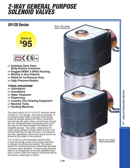
RESPONSE TIME
OPEN
CLOSE
4 to 15 ms 4 to 15 ms
4 to 15 ms 4 to 15 ms
4 to 15 ms 4 to 15 ms
4 to 15 ms 4 to 15 ms
4 to 15 ms 4 to 15 ms
4 to 15 ms 4 to 15 ms
4 to 15 ms 4 to 15 ms
73.7 (2.90)
106.7 (4.20) 2
OUT Port Identification: 2-IN/1-OUT
Dimensions: mm (in)
MOST POPULAR MODELS HIGHLIGHTED!
To Order (Specify Model Number)
NPT MODEL NO. PRICE FITTING ORIFICE CV
TYPICAL APPLICATIONS ߜ Automation ߜ Humidifiers ߜ Water Treatment ߜ Dispensing ߜ Laundry, Dry Cleaning Equipment ߜ Machine Tools ߜ Vending Machines
The direct-acting SV121 to SV127 solenoid valves consist of a coil, plunger, and sleeve assembly. In a normally closed state, a plunger return spring holds the plunger against the orifice, preventing flow through the valve. When current flows through the coil, a magnetic field is produced and it turns the stop into an electromagnet that attracts the magnetic plunger. This action compresses the return spring, allows the body orifice to open, and permits fluid flow through the valve. The pressure and flow capabilities of the direct-acting valves are limited by the power of the solenoid.
切断阀使用手册-电子版

80
Kg 553 2415 5355
100 9345
响应时间
ta ≤0.5 秒
150
200
250
19005 33705 51975
300 75075
五、切断阀工作原理
从原理上来讲,SSV3000 系列切断阀是一种轴流式的切断阀,它的执行机构与 指挥器系统保证切断阀处于打开状态。
切断阀最主要的部件(阀筒)在阀体内是进行轴向运动的,所以当管道中有压力 的情况下不需要另外的旁通来先平衡气体。
警告
在安装、操作或维修 SSV3000 系列切断阀之前,必须先完整的阅读本
使用手册。与本切断阀的安全安装和操作规程要求不符合的操作都可能会导
致严重的伤亡事故。
一、简介
SSV3000 系列切断阀是安装在调压站或气体分输管线的自动进行切断的一种安 全装置。当下游的压力达到切断阀的切断设定压力时,切断阀能够快速切断供气。
银 红 白锌
AE100-PL+ PAL80 (bar)
0.5~2bar 0.8~3bar 2~4bar 3~6bar 4~8bar 6-15bar 10-20bar 15-30bar
/
超压切断压力范围
AE100-PL+ AE100-PL+
PAL80/HP
PAL81
(bar) / / / / / / / /
根据不同的切断压力范围,AE100 执行机构有不同的型号可供选择(见表 3)。 AE100-PL 系列执行机构和指挥器,在正常工况下,由于 PAL80 指挥器的阀口是 关闭的,指挥器的中腔是与大气有一个小孔相通的,所以切断阀的执行机构的皮膜腔 内没有压力。 当下游的压力升高超过切断的设定压力时,指挥器的阀口打开,下游的气体进行 入指挥器的中腔,进而进入到执行机构的皮膜腔中,使得执行机构的叶轮移动,切断 阀关闭。 当下游的压力低于 PAL81 设定的超低压切断压力时,PAL81 的阀口打开,下游的 气压使切断阀关闭。 我们可以根据需要选择超高压或超低压切断或两个同时选择。
燃气切断阀使用说明
燃气切断阀使用说明标题:燃气切断阀使用说明引言:燃气切断阀是家庭和商业建筑中保障安全的重要装置之一。
它可以切断燃气供应,以防止火灾、爆炸和其他安全事故的发生。
本文旨在为读者提供关于燃气切断阀的使用说明,包括其功能、安装和操作细节,以及常见问题的解答。
通过深入的探讨,希望读者能够对燃气切断阀有更全面、深刻和灵活的理解。
正文:1. 燃气切断阀的功能燃气切断阀是安装在燃气管道中的装置,用于控制燃气的供应。
它可以通过手动或自动操作将燃气供应切断。
当发生火灾、泄漏、管道破裂或其他紧急情况时,切断阀可以立即切断燃气供应,以减少潜在危险。
2. 燃气切断阀的安装在安装燃气切断阀之前,首先需要确认合适的安装位置。
通常,切断阀应安装在燃气进入建筑物之前的主要燃气管道上。
安装时需要遵循相关的建筑和安全规范,确保切断阀能够正常工作且易于操作。
3. 燃气切断阀的操作燃气切断阀的操作一般分为手动和自动两种方式。
3.1 手动操作:手动操作是最常见的方式,通过手动旋转或折叠切断阀上的手柄或把手来控制燃气的开关。
在紧急情况下,只需迅速将手柄或把手旋转到关闭位置,即可切断燃气供应。
在日常使用中,定期检查手动操作是否灵活,确保切断阀能够正常操作。
3.2 自动操作:自动切断阀通常通过与火灾探测器和报警系统相连,一旦探测到火灾或泄漏,自动切断阀会自动关闭燃气供应。
这种方式不需要人工干预,能够实现及时、准确的切断。
4. 常见问题解答在使用燃气切断阀的过程中,可能会遇到一些常见的问题,下面是对其中几个问题的解答:4.1 燃气切断阀是否需要定期维护?是的,定期维护燃气切断阀非常重要,它可以确保切断阀的正常操作。
定期检查切断阀的密封性能、操作机构和阀体是否有损坏或老化的迹象,并及时进行维修或更换。
4.2 如何判断燃气切断阀是否正常工作?正常情况下,燃气切断阀应该在打开和关闭时都有明显的操作感觉。
当切断阀关闭时,燃气供应应立即停止,无任何泄漏或滴漏的现象。
- 1、下载文档前请自行甄别文档内容的完整性,平台不提供额外的编辑、内容补充、找答案等附加服务。
- 2、"仅部分预览"的文档,不可在线预览部分如存在完整性等问题,可反馈申请退款(可完整预览的文档不适用该条件!)。
- 3、如文档侵犯您的权益,请联系客服反馈,我们会尽快为您处理(人工客服工作时间:9:00-18:30)。
燃气安全截断阀目录
◆产品简介
◆型号含义
◆主要技术参数
◆工作原理与结构
◆安装与使用
◆维护与维修
◆开箱与贮存
◆售后服务
◆订货需知
一、产品简介
1.1用途:AJZ系列燃气安全截断阀是一种用于
燃气输配系统,特别是燃气调压站的新型安
全装置。
当系统中的任何异常引起监控压力
达到预定的警戒值(超高压或超低压)时该
装置迅速自动截断气流,起到安全保护作用。
1.2特点:截断精度高,响应速度快;内部旁通,
易于开启;可作超高压/超低压截断,关闭严
密;利用介质自身压力自动截断,也可手动
截断;可远传控制监控和报警;操作简便,
易于在线维修。
1.3适用介质:天然气、人工煤气、液化石油气、
空气以及其它无腐蚀性气体。
二、主要技术参数
公称压力(MPa):PN1.6 PN2.5 PN4.0 PN6.4 PN10.0
公称通径(mm):DN25 DN50 DN65 DN80 DN100 DN150 DN200
截断精度: 根据不同的供气压力和条件,其精度为±1% ~±5% 工作温度:-35~+60℃
三、工作原理与结构
3.1工作原理:作为一种保证调压器以及燃气用户安全的安全保护装置,当监控处的气体压力高于或低于相应的设定的截断压力时,安全截断阀迅速动作以切断气流,防止事故发生。
AJZ系列安全截断阀由监控装置(A)、切断机构(B)阀头行程显示器(C)、复位装置(D)等部件组成(图1).
通过信号管反馈作用在监控膜如图1所示,截断阀正常运行情况下,下游监控处气体的压力 P
2
(F)上的压力与预先设定的弹簧(G)作用在监控膜上的压力达到比较精确的平衡,执行器中限位钩(K)与切断机构中的杠杆(H)保持扣上,阀头(I)一直处于完全开启状态。
当由设备故障或其它原因引起下游气体压力升高或降低时,作用在监控膜上的压力与弹簧力不平衡将带动撞杆(J)向右或向左轴向移动触动切断机构,使杠杆(H)与限位钩(K)脱开,同时阀头在主弹簧(L)的作用下迅速截断气流。
图1:工作原理图
3.2外形结构尺寸
图2外型结构图
连接法兰标准: JB/T81-94
JB/T82-94
3.3、切断器装配图
图3安全切断阀装配图
四、安装与使用
4.1安装
4.1.1检查燃气输配管线压力和下游监控处压力是否与截断阀铭牌上所示压力相符
4.1.2检查截断阀气流箭头方向是否与管线压力方向一致
4.1.3请参照主要结构尺寸之图3和表2,选择与阀体适配的法兰安装截断阀
4.2典型安装方式见图3(仅供参考)
4.2.1一般常用于对气体压力调节器的工作情况进行监控
4.2.2对管线压力直接监控
4.3使用
AJZ系列安全截断阀为自动切断,手动复位开启。
开启状态,阀头行程指示器处于上方开位置;切断状态,阀头行程指示器处于下方关位置。
4.3.1 通气步骤
4.3.1.1 确认截断阀处于开启状态。
(如截断阀处于切断状态,超高压安全截断阀按4.3.2复
位开启。
而带超低压截断的安全截断阀则按4.3.3复位开启)
4.3.1.2 关闭检测口旋塞和信号旋塞(图4)
4.3.1.3上下游通气。
确认各部位压力正确后,缓慢开启信号旋塞,截断阀即可正常使用。
4.3.2 超高压截断安全阀的复位开启(普通型)
4.3.2.1 关闭监控处下游阀门和信号旋塞,开启检测口旋塞待监控器内气体排空后将其关闭。
4.3.2.2打开机构盒盖,盒子右上部有一红色复位杆(M),将其推向右上方,使机构中杠杆(N)扣上。
4.3.2.3取下机构盒左下角四方工具(O)套在复位装置(D)的四方轴上,顺时钟转动四方轴使限位钩与杠杆(H)扣上。
4.3.2.4将工具放回原处,盖上盒盖,至此机构复位完成。
4.3.2.5排除故障,确认监控处压力正常后,缓慢开启信号旋塞,截断阀即可投入正常运行。
4.3.3带超低压截断功能的安全截断阀的复位开启。
4.3.3.1 关闭监控处下游的阀门和信号旋塞,开启检测口旋塞待监控器内气体排空后将其关闭。
4.3.3.2 重复4.3.2.3的操作(不扣上杠杆H使阀头开启通气即可)
4.3.3.3 排除故障,确认监控处压力正确后,缓慢开启信号旋塞。
使撞杆处于正常位置。
4.3.3.4 重复4.3.2.2 4.3.2.3 4.3.2.4中的复位动作,至此截断阀复位开启完成,可投入
正常运行。
4.3.4 截断阀切断压力的设定
用四方工具柄部插入调压螺塞(P)孔中并将其向下转动,则截断阀动作压力设定值增高,
反之降低。
用户可跟据需要在该型号监控器压力设定值范围内自行调整设定监控压力。
如
超出调整范围,只需更换监控器即可。
五、维护与维修
5.1必须由有经验的熟练人员进行维护与维修,如尚需任何信息可与本厂售后服务部或授权的经
销商联系。
5.2建议对截断阀进行定期维护检查,主要是机构的灵活性和各部的密封性,其周期可比同等条
件下使用的调压器的维护周期延长1~2倍。
六、开箱与贮存
6.1开箱前应检查外部包装的完整性,开箱后根据装箱清单核对箱内产品的规格型号、数量、完整性和备件配置情况。
6.2随机文件
a.产品使用说明书
b.产品合格证
c.装箱清单
6.3截断阀的存放应符合以下条件:
a.防雨防潮
b.不应有明显的振动
c.环境温度:-20℃~+60℃
d.相对湿度:不大于75%
e.环境不含腐蚀性气体
七、售后服务
7.1本厂建立专门的售后服务部门,负责本厂产品的跟踪和维修。
7.2整个系统安装调试完毕投入正常使用一年内,本厂负责免费保修。
7.3一年保修期结束以后,本厂仍负责长期维修服务。
7.4本厂免费为用户培训操作人员。
7.5设备出现故障后,请用户及时与本厂联系,我们将派出专业维修人员上门服务。
7.6本厂各类零配件充足,能确保用户需求。
八、订货须知
用户在订货时必须提供以下参数:
a.气体种类
b.公称进口压力
c.截断压力范围
d.所需公称口径或最大流量
e.可选功能中的特殊要求(普通型无超低压截断、远传控制监控和报警功能)
f.用户的其它要求。
