LA-400使用手册
JBL PRX400 音响系统用户指南说明书

S afetyCAUTION: Before installation, turn-off any part of the audio system to Arrayprevent damage to the speaker or system components.f eatureSHorn Loaded Compression Driver• 1" Titanium diaphragm• Horn loading provides off axis response and midrange vocal clarity• Overload protection circuitry• Field replaceable12" Passive Speaker• High efficiency, low distortion design• High output with minimal power requirementsHigh Output Enclosure• Bass reflex design• Large volume for better low frequency response• Integrated ergonomically designed handles• Interlocking corners allow stacking of multiple cabinets• Dual Input- 5-way binding posts- 1/4” phono jack• Heavy gauge steel mesh grille• Industry standard 1-3/8” pole socketI nStallatIonS pecIfIcatIonSFEA TURE VALUESPEAKER CONFIGURATION ........ 2-Way Passive LoudspeakerDRIVER DIAMETER.............................1" Compression Driver / 12" Woofer POWER HANDLING ........................ 150 Watts RMS / 300 Watts MAX IMPEDANCE ........................................ 4ΩDESIGN .................................................2nd Order Vented (Ported)FREQUENCY RESPONSE .................33Hz - 22kHzSENSITIVITY .......................................... 92dBENCLOSURE MATERIAL................... 18mm (0.71")STAND RECEPTACLE.........................1.375" (35mm)DIMENSIONS....................................... (H) 24.8" x (W) 14.37" x (D) 12.59" 630mm x 365mm x 320mmWEIGHT (ea).........................................41 Lbs. (18.59kg)WARRANTY ..........................................1 YearAmplifier/T unerFor stereo amplifier/tuners, youcan connect a stereo pair of speak-ers to the LEFT and RIGHT out-puts. Connect the amplifier (+) tothe speaker (+) and the amplifier(-) to the speaker (-). For properstereo imaging, connect the LEFToutput to the LEFT speaker andthe RIGHT output to the RIGHTspeaker.Example SpeakerStand SetupRFDJ1 shownwith optionalspeaker stands.Stands notincluded.Rockford Corporation offers a limited warranty on Rockford Fosgate products on the following terms:Length of Warranty• Loudspeakers – 1 Y ear (receipt required).• Any Factory Refurbished Product – 90 days (receipt required)What is CoveredThis warranty applies only to Rockford Fosgate products sold to consumers by Authorized Rock-ford Fosgate Dealers in the United States of America or its possessions. Product purchased by consumers from an Authorized Rockford Fosgate Dealer in another country are covered only by that country’s Distributor and not by Rockford Corporation.Who is CoveredThis warranty covers only the original purchaser of Rockford product purchased from an Autho-rized Rockford Fosgate Dealer in the United States. In order to receive service, the purchaser must provide Rockford with a copy of the receipt stating the customer name, dealer name, product purchased and date of purchase. Products found to be defective during the warranty period will be repaired or replaced (with a product deemed to be equivalent) at Rockford’s discretion.What is Not Covered1. Damage caused by accident, abuse, improper operations, water, theft, shipping2. Any cost or expense related to the removal or reinstallation of product3. Service performed by anyone other than Rockford or an Authorized Rockford Fosgate Service Center4. Any product which has had the serial number defaced, altered, or removed5. Subsequent damage to other components6. Any product purchased outside the U.S.7. Any product not purchased from an Authorized Rockford Fosgate DealerLimit on Implied WarrantiesAny implied warranties including warranties of fitness for use and merchantability are limited in du-ration to the period of the express warranty set forth above. Some states do not allow limitations on the length of an implied warranty, so this limitation may not apply. No person is authorized to assume for Rockford Fosgate any other liability in connection with the sale of the product.How to Obtain ServiceContact the Authorized Rockford Fosgate Dealer you purchased this product from. If you need further assistance, call 1-800-669-9899 for Rockford Customer Service.Y ou must obtain an RA# (Return Authorization number) to return any product to Rockford Fosgate.Y ou are responsible for shipment of product to Rockford.EU WarrantyThis product meets the current EU warranty requirements, see your Authorized dealer for details.l ImIted W arranty S tatementRockford Fosgate600 South Rockford DriveT empe, Arizona 85281 U.S.A.In U.S.A., (480) 967-3565 - Customer Service 1-800-669-9899© 2010 Rockford Corporation. All rights reserved.Rockford Fosgate® and the Rockford Fosgate® “Diamond R” areregistered trademarks of Rockford Corporation.01/2010 E.W .R.1230-56250-02Printed in China。
400KVA 60Hz变频电源用户使用手册---雷乐士

外部保护: __________________________________________________________________________________ 5 远程控制和信号的连接 _____________________
Eaton AQB-L400适配器套件说明说明书
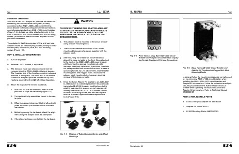
Page 2Functional DescriptionAn E aton AQB-L400 Adapter Kit provides the means for converting the normally male configured primary connections of an AQB-L400/LL400 current limiting circuit breaker to female configured primary connections, normally associated with an AQB-LF400 circuit breaker (Figure 1-5). A close out plate, attached directly to the front of the AQB-L400 circuit breaker with four mounting screws, provides the deadfront cover required to complete the conversion.The adapter kit itself is comprised of line and load side adapter blocks, six female spring loaded primary connection adapters, a close out plate, and four mounting screws (Figure 1-3).PART 2. INSTALLATION/OPERATIONa.Turn off all power.b.Remove LF400 breaker, if applicable.c.The standard male type slip connectors shall beremoved from the AQB-L400/LL400 circuit breaker.The threaded end of the female connection adapters attaches in their place. The other end of the femaleconnection adapters provides the female slip connections required for the AQB-LF400 configuration.d.Mount the tulips to the line and load ends.1.Note that 4 tulips are offset mounted on theirpads and 2 tulips are centered (Figure 1-4).2.The centered tulip assemblies mount to the center pole.3.Offset tulip assemblies mount to the left and rightpoles, with the tulips oriented to the outside ofthe breaker.4.Before tightening the hardware, check the alignment using the adapter block as a template.5.If the alignment is correct, tighten the hardware.I.L. 15578AA CAUTIONTO PROPERLY REMOVE THE ADAP TED AQB-L400/LL400 CIRCUIT BREAKER, UNSCREW THE BOLTSLOCATED IN THE ADAP TER BLOCK, NOT THEBREAKER MOUNTING BOLTS LOCATED IN THEBREAKER FRAME.e.The adapter block is mounted to the circuit breakerusing breaker mounting bolts.f.The modified breaker is mounted to the LF400mounting blocks using hardware supplied with theadapter block.g.After mounting the breaker on the LF400 block,attach the close out plate to the front. Once attachedto the front of the AQB-L400/LL400 circuit breakerwith four mounting screws, the close out plateinsures a deadfront installation. In addition, the closeout plate provides front access to the circuit breaker'soperating handle, trip unit adjustments, lower breakermounting bolts and megger holes. Access to theadapter block mounting bolts, however, requiresremoval of the close out plate.h.Since the E aton Adapter Kit applied to an AQBL400/LL400 breaker is a direct replacement for an alreadyinstalled AQB-LF400 breaker, modifications to theexisting bus mounting system are not required. Analready adapted AQB-L400/LL400 breaker can bemounted on existing blocks, and secured in placewith the provided upper and lower adapter blockbolts (Figure 1-6).Fig. 1-4. Closeup of Tulips Showing Center and OffsetMountingsEffective October 1997I.L. 15578AFig. 1-5. Rear View of Navy Type AQB-L400 CircuitBreaker and Adapter Kit Combination Displaying Female Configured Primary ConnectionsEffective October 1997Page3Fig. 1-6. Navy Type AQB-L400 Circuit Breaker andAdapter Kit Combination Plugged Into MaleMounting BlocksIn general, follow the mounting procedures normally usedfor mounting any AQB-LF400 circuit breaker, wheninstalling the AQB-L400/LL400 circuit breaker andAdapter Kit combination. Follow the instructions and procedures provided with the AQB-L400/LL400 circuitbreaker when operating the AQBL400/LL400 andAdapter Kit combination. Refer to Technical Manual1240C33H01PART 3. REPLACEABLE PARTSa.L400/LL400 plus Adapter Kit: See E atonb.Adapter Kit: 6590C82G01c.LF400 Mounting Block: 6590C82G03Page4E at onMoon Township, Pennsylvania U.S.A.Style No. 69C0670H02 Effective October 1997 Printed in U.S.A./CCI I.L. 15578AI.L. 15578AFile 29-000Instructions for Use of E aton Adapter Kit and Navy Type AQBL400 MoldedCase Circuit Breaker Combination in AQB-LF400 ApplicationsA WARNINGDO NOT ATTEMPT TO INSTALL OR PERFORM MAINTENANCE ON EQUIPMENT WHILE IT IS ENERGIZED.DEATH, SEVERE PERSONAL INJURY, OR SUBSTANTIAL PROPERTY DAMAGE CAN RESULT FROM CONTACT WITH ENERGIZED EQUIPMENT. ALWAYSVERIFY THAT NO VOLTAGE IS PRESENT BEFOREPROCEEDING WITH THE TASK, AND ALWAYS FOLLOW GENERALLY ACCEPTED SAFET Y PROCEDURES.EATON IS NOT LIABLE FOR THE MISAPPLICATIONOR MISINSTALLATION OF ITS PRODUCTS.The user is cautioned to observe all recommendations,warnings, and cautions relating to the safety of personneland equipment, as well as all general and local healthand safety laws, codes, and procedures.The recommendations and information contained hereinare based on Eaton experience and judgement, butshould not be considered to be all inclusive or coveringevery application or circumstance which may arise. If anyquestions arise, contact Eaton for further information orinstructions.Fig. 1-1 Standard Navy Type AQB-L400 Molded CaseCircuit BreakerEffective October 1997 Supersedes I .L. 1557B dated June 1992PART 1. INTRODUCTIONGeneral InformationThe Navy Type AQB-L400 or AQB-LL400 circuitbreakers (Figure 1-1), when supplied with a factoryinstalled Eaton AQB-L400 Adapter Kit (Figures 1-2 and1-3), can be installed directly into Navy Type AQB-LF400applications. This combination of an AQB-L400/LL400circuit breaker and the Eaton Adapter Kit provides adirect one to one current limiting type L400 circuitbreaker replacement for an already installed fused typeLF400 circuit breaker. Existing AQB-L400/LL400 circuitbreakers in the field (manufactured prior to August, 1992)may need a factory modification to accept the AdapterKit. Contact Eaton for details, if there are any questions.Fig. 1-2. Navy Type AQB-L400 Molded Case CircuitBreaker with Adapter Kit Factory InstalledFig. 1-3. E aton Adapter Kit Parts BeforeInstallation。
L4000 智能控制器使用说明

L-4000智能控制器使用说明L4000智能控制器基本参数工作电压:220V外型尺寸:390*235*80 (H*W*D)最大负载:6000W单路负载:可调灯光1500W 开关灯光3000W功能简介L-4000灯光/空调智能控制器是专为KTV设计的一款具备灯光亮度调节、中央空调控制、可编程的智能型灯光/空调控制器。
1、设有6路大功率可调光及4路大功率继电器,满足各种灯光应用的需求2、可直接通过串口与机顶盒或电脑连接3、可直接连接灯光控板,脱离点歌系统及中控盒独立运行4、可对任一模式下的灯光状态进行编程,实现任意灯光搭配5、灯光控制器上可直接按键操作选择灯光模式及调节灯光亮度6、灯光亮度均衡,通过在不同模式下设置不同的亮度,实现场景效果切换,减少了灯光的开关次数,延长灯光使用寿命7、可外接遥控器对灯光进行遥控控制(选配)8、中央空调智能控制,配合点歌系统可实现远程开关空调9、配盒空调墙板通过温度探测,可智能控制风机及阀门的开关,减少能源浪费10、设有2组空调控制11、根据室温与设定温的比对,自动调节风速12、采用串口光电隔离技术,避免设备间的互相干扰灯光控制的设置一、灯光模式对应组的编程先关闭灯光控制器电源,按住设置及确认键不放,打开电源,等待约1秒,灯光控制器显示01并闪烁,表示01组,按△或▽键选择所要编程的组。
1、选择需要编程的组按△或▽键选择需要编程的组,按确认键进入该组编程设置;2、设置该组对各路灯光的控制状态数码管显示J1,对应指示灯指示出该模式下灯光的控制状态,亮表示控制,闪烁表示不控制,不亮表示强制关。
按▽键选择要设置的灯光,J1-JA表示灯光控制器的10路,按设置键进行设置,按确认键进入下一步设置;3、设置组的开关模式显示H1表示固定模式,显示H0表示开关模式(固定模式:例如,当按K歌时1、2、3路亮,再次按K歌时还是1、2、3路亮;开关模式:例如,当按K歌时1、2、3路亮,再次按K歌时1、2、3路灭),按设置键进行选择,按确认键进入下一步设置;4、设置组的亮度继承方式显示L1表示固定亮度,显示L0表示继承亮度(固定亮度,例如:进入K歌模式后,将其亮度由60调到80,第二次进入K歌模式时它的默认亮度还原为60;继承亮度,例如:进入K歌模式后,将其亮度由60调到80,第二次进入K歌模式时它的默认亮度为80)。
stvdioduela400功放说明书

stvdioduela400功放说明书
这台stvdioduela400在外观上,就传承了工艺设计元素,同时融入进了与时俱进的时尚元素,形成其独有的魅力。
黑铝质外壳有别于传统的平面结构,层次错落的凹凸版块有更好的立体设计感,转角处的圆滑处理更加便于安装。
两侧的散热栅格线条稍微内凹一些,间距之间略有不同,这些细微的变化使得产品更加别致,同时使机器有了快速冷却的出色散热效果。
细节处的恰到好处以及制造上的精良,提升了机器的质感,完全呈现出现代工艺的美感。
采用左右两侧接线方式,一侧是信号输入及处理端口,包括了两组高电平信号输入和两组RCA信号输入,以及连接DSP等其他设备的PREOUT前置输出;另一侧是大电流的电源连和喇叭连接端口。
从两连接端口的设置来看,stvdioduela400不仅是一台4声道功率放大器,还可以通过接线方式可选择3声道和2声道的运转模式,以更加灵活的应用来应对当下越来越丰富的改装玩法。
在4欧工作情况下,可以有120W×4或120W ×2加400Wx1的功率输出,桥接后有400W×2的大功率输出;在2
欧工作情况下功率为200Wx4。
玩法更加多样的是,AV Quattro根据系统的需求,通过不同的线材连接方式形成120Wx2@4欧+200Wx2@2欧,或200Wx2@2欧+400Wx1@4欧等多种功率输出组合,不管是高端大功率的扬声器套装还是低音产品,stvdioduela400通通都能满足。
Neopulse 400 G 焊机说明书
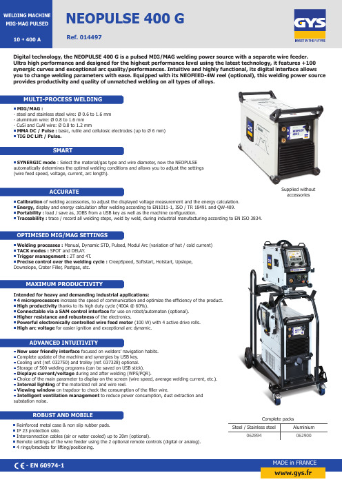
MADE in FRANCENEOPULSE 400 G10 Ref. 014497MIG/MAG :- steel and stainless steel wire: Ø 0.6 to 1.6 mm - aluminium wire: Ø 0.8 to 1.6 mm - CuSi and CuAl wire: Ø 0.8 to 1.2 mmMMA DC / Pulse : basic, rutile and cellulosic electrodes (up to Ø 6 mm) TIG DC Lift / Pulse.Supplied without accessoriesReinforced metal case & non slip rubber pads. IP 23 protection rate.Interconnection cables (air or water cooled) up to 20m (optional).Remote settings of the wire feeder using the 2 optional remote controls (digital or analog). 4 rings/brackets for lifting/positioning.Digital technology, the NEOPULSE 400 G is a pulsed MIG/MAG welding power source with a separate wire feeder. Ultra high performance and designed for the highest performance level using the latest technology, it features +100 synergic curves and exceptional arc quality/performances. Intuitive and highly functional, its digital interface allows you to change welding parameters with ease. Equipped with its NEOFEED-4W reel (optional), this welding power source provides productivity and quality of unmatched welding on all types of alloys.www.gys.frIntended for heavy and demanding industrial applications:4 microprocessors increase the speed of communication and optimize the efficiency of the product. High productivity thanks to its high duty cycle (400A @ 60%).Connectable via a SAM control interface for use on robot/automaton (optional). Higher resistance and robustness of the electronics.Powerful electronically controlled wire feed motor (100 W) with 4 active drive rolls. High arc voltage for easier ignition and exceptional arc dynamic.SYNERGIC mode : Select the material/gas type and wire diameter , now the NEOPULSE automatically determines the optimal welding conditions and allows you to adjust the settings (wire feed speed, voltage, current, arc length).New user friendly interface focused on welders’ navigation habits. Complete update of the machine and synergies by USB key. Cooling unit (ref. 032750) and trolley (ref. 037328) optional. Storage of 500 welding programs (can be saved on USB stick). Displays current/voltage during and after welding (WPS/PQR).Choice of the main parameter to display on the screen (wire speed, average welding current, etc.). Internal lighting of the motorized roll and wire reel.Viewing window on trapdoor to check the consumption of the filler wire.Intelligent ventilation management to reduce power consumption, dust extraction and substation noise.Welding processes : Manual, Dynamic STD, Pulsed, Modul Arc (variation of hot / cold current) TACK modes : SPOT and DELAY . Trigger management : 2T and 4T .Precise control over the welding cycle : CreepSpeed, Softstart, Hotstart, Upslope, Downslope, Crater Filler , Postgas, etc.Complete packsSteel / Stainless steelAluminium 062894062900Calibration of welding accessories, to adjust the displayed voltage measurement and the energy calculation. Energy, display and energy calculation after welding according to EN1011-1, ISO / TR 18491 and QW-409. Portability : load / save as, JOBS from a USB key as well as the machine configuration.Traceability : trace / record all welding steps, weld by weld, during industrial manufacturing according to EN ISO 3834.NEOPULSE 400 GRef. 014497Interconnection cablesTECHNICAL DATAACCESSORIES & CONSUMABLES。
LS400使用说明书

电控悬架系统实训台(Ls400)实训指导书广州市三项教学仪器有限公司一.操作说明1.使用前检测蓄电池电压是否充足;2.连接蓄电池正负极电源(切勿连接错误,否则容易导致线路短路);3.打开点火开关,检测故障指示灯、及其它信号表是否正常。
4.操作各演示开关,模拟各种不同路面的不同工作状况;5. 演示开关说明1)车速开关(加速演示开关):防止坐尾,后减震器工作;2)刹车开关(减速演示开关):防止车点头,前减震器工作;3)高度控制开关:演示空气悬架工作状况;4)转角传感器(演示左右转向不同工作状况):防止车侧倾;5)加减开关:演示汽车承载重量,控制单元自动调整车身高度;二.结构原理与工作过程传统的悬架系统一般具有固定的弹簧刚度和减振器阻尼,不能同时满足汽车行驶平顺性和操纵稳定性的要求。
例如:降低弹簧刚度,平顺性会变好,使乘坐舒适,但由于悬架偏软会使操纵稳定性变差;而增加弹簧刚度会提高操纵稳定性,但较硬的弹簧又使车辆对路面的不平度很敏感,使平顺性降低。
因此,理想的悬架系统应在不同的使用条件下具有不同的弹簧刚度和减振器阻尼力,这样既能满足平顺性的要求又能满足操纵稳定性的要求。
电子控制悬架系统就是这种理想的悬架系统。
电子控制悬架系统主要有半主动悬架和主动悬架两种。
传统的悬架系统一般具有固定的弹簧刚度和减振器阻尼,不能同时满足汽车行驶平顺性和操纵稳定性的要求。
例如:降低弹簧刚度,平顺性会变好,使乘坐舒适,但由于悬架偏软会使操纵稳定性变差;而增加弹簧刚度会提高操纵稳定性,但较硬的弹簧又使车辆对路面的不平度很敏感,使平顺性降低。
因此,理想的悬架系统应在不同的使用条件下具有不同的弹簧刚度和减振器阻尼力,这样既能满足平顺性的要求又能满足操纵稳定性的要求。
电子控制悬架系统就是这种理想的悬架系统。
电子控制悬架系统主要有半主动悬架和主动悬架两种。
半主动悬架是指悬架元件中的弹簧刚度和减振器阻尼力之一可以根据需要进行调节。
而主动悬架能根据需要自动调节弹簧刚度和减振器的阻尼力,从而能够同时满足汽车行驶平顺性和操纵稳定性等各方面的要求。
拉雷尔电子有限公司 LA40 低成本、通用模拟输入数字面板表仪说明书

LAUREL ELECTRONICS, INC.L40 Low-Cost, Universal Analog Input Digital Panel MeterUser Selectable Ranges•DC voltage: ±60.0 mV, ±200.0 mV, ±2.000V, ±20.00V, ±200.0V, ±400V•DC current: ±20.00 mA, ±5.00A•AC rms voltage: 60.0 mV, 200.0 mV, 2.000V, 20.00V, 200.0V, 400V•AC RMS current: 20.00 mA, 5.00A AC•Process: 4-20 mA, 0-10V•Thermocouple types: K, J, E, N, L, C, R, S, B, T•RTD types: Pt100, Pt500, Pt1000, Ni100, Ni200, Ni1000•Thermistor types: NTC, PTC•Resistance: 0-9.999 kohm, 0-99.99 kohm•Potentiometer input: 200Ω to 50 kΩOptions• 1 or 2 mechanical relays, 8A, 250 Vac•Isolated analog output•RS485 Modbus RTU data outputStandard Features•Universal power: 18 Vac/dc to 265 Vac/dc•1/8 DIN case with 3 front panel keys•Display: 4 red LED digits, 14.2 mm (0.56")•Typical accuracy: 0.2% of full scale•Removable screw-clamp connectors•External control inputDescriptionModel L40 is a low-cost, universal meter for 65 user selectableanalog input signal types and ranges. These include DC voltageand current, AC RMS voltage and current, process signals (4-20mA, 0-10V), thermocouples (10 types, °C or °F), RTD (6 types,°C or °F), thermistors (NTC or PTC), resistance (0-10k or 0-100kohms), and potentiometer inputs. The same meter handles allsignal types with no need for a plug-in signal conditioner board.A universal power supply accepts voltages from 18V to 265V,AC or DC, so that power can be 24 Vdc or worldwide AC power.The meter conforms to the popular 1/8 DIN size standard andfeatures four 14.2 mm (0.56") bright red LED digits. The displayis user scalable for all input types other than temperature.The base L40, as shipped by Laurel,is set up so that 400 Vac input reads400. To change to another signal typeor range, pry off the meter faceplate,push out the electronics, and placejumpers as illustrated in the manual.The jumper positions are well labeled,and the jumpers have a large, easy-to-grasp handle. Also makesoftware selections using front panel keys. If you want Laurel oryour distributor to set jumpers and do the front panel program-ming for you, order the FS option.Extensive software features add flexibility to this low costmeter. Programmable features include five levels of displaybrightness, min and max capture, dual scaling selectable by anexternal control input, a deadband around 0 for AC measure-ments, a moving average digital filter, a "count by" function,hysteresis for alarm operation, a user-configurable fast accessmenu, and selectable password protection. Further flexibility isprovided by 1 or 2 optional output boards, which can be added atany time.Additional flexibility is provided by optional output boards,which can be added at any time.•An Option 1 board can plug into the display board. This canbe a single 8A relay board, an isolated active or passive 4-20mA analog output board, or an isolated Modbus compatibleRS485 serial data output board.•An Option 2 board can plug into the Option 1 board ifinstalled. This is another single 8A relay board. For example,this board allows an L40 to have and analog output and arelay output, or to have two relay outputs.Easily accessible electronicsSpecificationsDC Voltage & CurrentRange Resolution Input Resistance Max Signal Accuracy±60.0 mVdc 0.1 mV 1 MΩ 1000 mVdc < 0.25% FS±200.0 mVdc 0.1 mV 10 kΩ 1000 mVdc < 0.20% FS±2.000 Vdc 1 mV 100 kΩ 10 Vdc < 0.20% FS±20.00 Vdc 0.01V 1 MΩ 100 Vdc < 0.20% FS±200.0 Vdc 0.1 V 12 MΩ 400 Vdc < 0.20% FS±400 Vdc 1 V 12 MΩ 600 Vdc < 0.25% FS±20.00 mAdc 0.01 mA 4.7 Ω 1000 mAdc < 0.15% FS±5.00 Adc 10 mA 20 mΩ 7 Adc max, 7 sec < 0.25% FS AC RMS Voltage & CurrentRange Resolution Input Resistance Max Signal Accuracy60.0 mVac 0.1 mV 1 MΩ 1000 mVac < 0.3% FS200.0 mVac 0.1 mV 10 kΩ 1000 mVac < 0.3% FS2.000 Vac 1 mV 100 kΩ 10 Vac < 0.3% FS20.00 Vac 0.01V 1 MΩ 100 Vac < 0.3% FS200.0 Vac 0.1 V 12 MΩ 400 Vac < 0.3% FS400 Vac 1 V 12 MΩ 600 Vac < 0.3% FS20.00 mAac 0.01 mA 4.7 Ω 25 mAac < 0.5% FS5.00 Aac 10 mA 20 mΩ 7 Aac max, 7 sec < 0.5% FSProcess SignalsRange Scaling Input Resistance Max Signal Accuracy 4-20 mAdc -1999 to 9999 4.7 Ω 1000 mA < 0.15% FS0-10 Vdc -1999 to 9999 1 MΩ 100 Vdc < 0.20% FS Thermocouple Temperature ProbesTC Type Range °C Range °F AccuracyType K -100 to 1350°C -148 to 2462°F < 3°CType J -100 to 1200°C -148 to 2192°F < 3°CType E -100 to 1000°C -148 to 1832°F < 3°CType N -200 to 1300°C -328 to 2372°F < 3°CType L -100 to 900°C -148 to 1652°F < 3°CType C 0 to 2300°C 32 to 4172°F < 5°CType R 0 to 1768°C 32 to 3214°F < 3°CType S 0 to 1768°C 32 to 3214°F < 3°CType B 700 to 1828°C 1292 to 3322°F < 5°CType T -100 to 400°C -148 to 752°F < 3°C Pt and Ni RTD Temperature ProbesRTD Type Range °C Range °F AccuracyPt100 -200 to 700°C -328 to 1292°F < 1°CPt500 -150 to 630°C -238 to 1166°F < 1°CPt1000 -190 to 630°C -310 to 1166°F < 1°CNi100 -60 to 180°C -76 to 356°F < 1°CNi200 -60 to 120°C -76 to 248°F < 1°CNi1000 -60 to 180°C -76 to 356°F < 1°CNTC Thermistors (negative temperature coefficient)R25 Values Beta Values Resolution Accuracy 100Ω to 100.00 kΩ 2000 to 5500 1° or 0.1°, °C or °F < 1.5% of resistancePTC Thermistors (positive temperature coefficient)Main Series Range °C Range °F AccuracyKTY-121 -55 to 150°C -67 to 302°F < 1°C KTY-210, KTY-220 -55 to 150°C -67 to 302°F < 1°CResistanceRange Resolution Bias Current Accuracy0 to 5.000 kΩ 1 Ω 926 to 64 µA < 0.5% FS0 to 50.00 kΩ 10 Ω 86 to 20 µA < 0.5% FSPotentiometerPotentiometer Range Default Scaling Resistance Accuracy50Ω to 100.00 kΩ 0 to 100.0 Ω 200 Ω to 50 kΩ < 0.5% FSApplicable to All Signal TypesDisplayDigital readout 4 red LED digits, 7-segment, 14.2 mm (.56") digit height, 5 brightness levels Display range -1999 to 9999Update time 300 msecSensor break indication Display of "h.ovr" for overrange, "h.udr" for underrangeIndicator lamps 2 red LED alarm indicatorsPowerUniversal voltage 18 to 265 Vac/dcPower consumption < 1.5W meter only, < 2.5W meter with optionsIsolation 2500 VeffAnalog Output (1AOT option)Output level 4-20 mA, active or passive (selectable at connector)Maximum load 350 Ω active, 700 Ω passiveScaling Zero and full scale adjustable from -1999 to +9999 countsAccuracy < 0.5% FSUpdate time 400 msIsolation 1000 VdcRelay Outputs (1RL option for slot 1 or 2RL option for slot 2)Relay type Single 3-contact relay (NC, NO, common)Current rating 8A at 250 VacIsolation 2500 VrmdRS485 (1RS485 option for slot 1)Protocol Modbus RTUProgrammable addresses 1-247Supported function code 4 = "read the register"Data rates 9600 or 4800 baudIsolation 1000 VdcEnvironmentalOperating temperature 0°C to 50°CStorage temperature -20°C to 70°CSignal ConnectionsDimensionsOrdering GuideCreate a model number with line items separated by commas: L40, 1RL, IPC . Describe FS option separately.Base Meter L40Digital panel meter for 65 user-selectable analog signal types and ranges. Includes power from 18-265 Vac/dc. Without FS option, shipped with factory default settings of 0-400 Vac, display of 0-400.Custom Setup by Vendor FSJumper settings and front panel programming done by vendor as a service. Specify the signal type and range. For DC, AC, process and resistance signals which require scaling, specify min input, min reading, and max input, max reading. For temperature, specify 1° or 0.1° resolution and °C or °F. For NTC thermistors, specify R25 and beta.Slot 1 Option Board. Maximum of one. Shipped installed in meter. A1 M1 S1Single 8A relayIsolated, scalable 4-20 mA analog output Isolated RS485 output, Modbus RTUSlot 2 Option Board. Maximum of one. Requires slot 1 option board. Shipped installed in meter. A2Single 8A relayAdd-on Options & Accessories NL BL IPC BOX1 BOX2 CASE1 CASE3Front panel with button pads but no Laurel logo. Front panel without button pads or Laurel logo.Front panel cover, seals front of meter to NEMA 4X.Wall mount polycarbonate enclosure sealed to NEMA 4X.Wall mount polycarbonate enclosure sealed to NEMA 4X, plus IPC cover. Benchtop laboratory case for one 1/8 DIN meter. Benchtop laboratory case for two 1/8 DIN meters.。
Whirlpool 洗衣机用户手册说明书

E AWO/D 43115TABLA DE PROGRAMAS❉:opcional / Sí : requiere dosificación1)Para un mejor cuidado de la ropa, en este programa la velocidad de centrifugado está limitada a 400 rpm.5019 301 10258Whirlpool is a registered trademark of Whirlpool USAProgramaEtiquetas de mante-nimiento Tipo de lavado/notas- Para seleccionar la temperatura, respete las recomendaciones del fabricante quefiguran en la etiqueta de mantenimientoCarga máx.kgDetergentes y aditivos Opciones especialesVelocidad máx.centri-fugado rpmPre-lavado Lavado PrincipalSuavizante Pre-lavado Lavado en frío Anti-arrugas Centri-fugado variableAlgodón40 - 60 - 95 °C40 - 60 - 95 °CRopa de cama, mantelería, ropa interior, toallas, camisas, etc., de algodón o lino con suciedad de normal a elevada.Para ropa muy sucia también se puede seleccionar la opción adicional de “prelavado”.5,0❉Sí❉❉❉❉❉1000Sintéticos 30 - 40 - 60 °C 30 - 40 - 60 °CBlusas, camisetas, delantales etc., con un con un grado de suciedad leve o normal de poliéster (Diolen, T revira), poliamida (Perlon, Nylon) o mezclas con algodón.2,5❉Sí❉❉❉❉❉1000Delicados30 - 40 °C 30 - 40 °CCortinas y prendas delicadas, vestidos, faldas y blusas.1,5❉Sí❉❉❉—❉1000Carga diaria40 °C40 °CT extiles de algodón o fibra sintética con suciedad leve o normal.3,0—Sí❉—❉❉❉1000Lavado rápido30 °C30 °CRopa externa poco usada de algodón, poliéster, poliamida y mezclas con algodón.3,0—Sí❉—❉—❉1000LanaFrío - 40 °C- 40 °C Sólo prendas de lana sin acabado de fieltro, etiquetadas con la marca de lana y como resistentes al lavado a máquina.1,0—Sí❉—❉—❉1000Lavado a mano40 °C 40 °C T extiles de lino, seda, lana y viscosa etiquetados como “lavar a mano”.1,0—Sí❉———❉4001)Lencería 30 °C30 °CEste ciclo es especialmente adecuado para la lencería fina (se recomienda el uso de una red para lavado).1,0—Sí❉—❉—❉4001)Aclarado y centrifugado—Igual que el último aclarado y el centrifugado final del programa “Algodón”.5,0——❉———❉1000Centrifugado —Este programa incluye un centrifugado intensivo. Es el mismo que en el programa “Algodón”.5,0——————❉1000Centrifugado suave —Este programa utiliza un centrifugado suave. Es el mismo que en el programa “Lana”.1,0——————❉1000Descarga de agua—El agua se elimina sin centrifugar.—————————A.Indicación de “Puerta abierta”La lavadora posee unas funciones de seguridad automáticas gracias a las cuales reconoce e indicainmediatamente los posibles fallos y reacciona adecuadamente, p. ej.:B.Indicación de “Reparación”C.Indicación de “Grifo cerrado”D.Indicación de “Limpie la bomba”E.Selector de programasF.Botón “Inicio/Pausa”G.Selector de velocidad de centrifugadoH.Indicador de avance del programaI.Botón “Reinicio”DHC FIGEB A5019 301 10258Whirlpool is a registered trademark of Whirlpool USAAñada detergente según lo indicado en la primera página y en las instrucciones de uso. Cierre la puerta y gire el selector de programas al programa y la temperatura que desee. Destella el indicador luminoso situado junto al botón “Inicio/Pausa”.Pulse los botones de las opciones que desee. Seencienden los indicadores luminosos correspondientes.Si no es posible una combinación de programa y opciones adicionales, los indicadores luminosos se apagan automáticamente. Las combinaciones de opciones que no son posibles quedan automáticamente desactivadas.Botón “Prelavado”•Sólo para cargas de ropa muy sucia (por ejemplo con arena, suciedad gruesa). El tiempo del ciclo aumenta aproximadamente 15 minutos.Botón “Lavado en frío”•El agua sólo se calienta hasta 20 °C•Opción adecuada para ropa delicada con una temperatura máxima recomendada en la etiqueta de 30 °C.•Sólo se puede seleccionar en el paso de temperatura mínima de cada programa.Botón “Antiarrugas”•Puede utilizarse junto con los programas “Algodón”, “T ejidos sintéticos” y “Carga diaria” para facilitar el planchado.•Mejora la calidad del agua y realiza un centrifugado suave.Botón “Centrifugado variable”•Cada programa posee una velocidad máxima de centrifugado predefinida.•Pulse el botón para ajustar otra velocidad de centrifugado.•Si selecciona la velocidad de centrifugado “0” el centrifugado final se cancela pero los niveles intermedios del centrifugado continúan durante el aclarado. El agua se elimina sin centrifugar.DATOS DE CONSUMOPrograma T emperatura (°C)Carga(kg)Agua(l)Energía(kWh)Duración aprox. delprograma (horas :minutos)*Algodón 955,049**1,902:00Algodón ***605,0440,852:20Algodón 405,0440,602:00T ejidos sintéticos 602,550**0,70 1.30T ejidos sintéticos 402,5450,551:15T ejidos delicados 301,5500,500:45Prendas mixtas 403,0450,451:00Lavado rápido303,0400,400:30Lana401,0550,600:45Lavado a mano 401,0450,600:40Lencería301,0450,500:40Los datos de consumo se midieron en condiciones normalizadas de acuerdo con la norma CEI/EN 60456. Los valores de consumo en el hogar pueden variar respecto a los valores de la tabla según la presión y temperatura del agua, la carga y el tipo de lavado.*El indicador de tiempo restante puede desviarse de los valores de la tabla, porque considera las condiciones de la vivienda que corresponden en ese momento.**Para reducir la temperatura del agua, se agrega agua fría al final del ciclo principal de lavado, antes de que la bombavacíe el agua.***Programa de referencia para la etiqueta de energía.AÑADA DETERGENTE, CIERRE LA PUERTA Y SELECCIONE EL PROGRAMASELECCIONE CUALQUIER OPCIÓN Abra el grifo y pulse el botón “Inicio/Pausa”. Destella el indicador luminoso situado junto al botón“Inicio/Pausa”. El indicador de secuencia del programa muestra la fase actual del programa, de izquierda a derecha a través de Lavado, Aclarado y Centrifugado/Descarga.•Cuando termina la fase del programa, se apaga el indicador luminoso correspondiente.Antes del inicio y de la finalización de un programa, los indicadores luminosos se encienden para señalar que se puede abrir la puerta. Mientras el programa de lavado esté en marcha, la puerta permanece cerrada y por ninguna razón se debe intentar forzar su apertura. En caso de una necesidad urgente de abrirla durante un programa en marcha, consulte “Cancelación (Reinicio) de un programa antes de que termine”.“Reparación”El indicador de “Reparación” se puede encender por el fallo de un componente eléctrico. Consulte la “Guía para la solución de problemas” incluida con lasinstrucciones de uso; si el fallo continúa, póngase en contacto con el Servicio posventa.“Grifo cerrado”La lavadora no recibe alimentación de agua o es insuficiente. Abra el grifo; si la indicación sigue encendida, consulte la “Guía para la solución de problemas” incluida con las instrucciones de uso.“Limpie la bomba”La lavadora no descarga el agua. Compruebe si el tubo de descarga está doblado o si hay que limpiar el filtro; en este último caso, consulte en las instrucciones de uso (“Extracción del filtro”).•T odos los indicadores de secuencia delprograma están apagados y se enciende el indicador de “Puerta abierta”.1.Gire el selector de programas a la posición de “Apagado/O”.2.Cierre el grifo.3.Abra la puerta y retire la ropa.4.Deje la puerta entreabierta para facilitar el secadodel tambor.1.Pulse el botón “Inicio/Pausa” para detenertemporalmente el programa. El indicador destella.2.Seleccione el nuevo programa (con latemperatura), las opciones suplementarias y (si lo desea) otra velocidad de centrifugado.3.Pulse nuevamente el botón “Inicio/Pausa”. Elnuevo programa continúa el programa de lavado en la fase en que se interrumpió el anterior. En este programa no es necesario añadir más detergente.El botón “Reinicio” permite cancelar un programa antes del final.•Pulse el botón “Reinicio” durante, almenos, 3 segundos. El agua se descarga antes de poder abrir la puerta.INICIO DEL PROGRAMAINDICACIÓN DE “PUERTA ABIERTA”INDICACIONES ROJAS FIN DEL PROGRAMACAMBIO DE PROGRAMA O DE OPCIONES DESPUÉS DEL INICIO DEL PROGRAMA CANCELACIÓN (REINICIO) DE UN PROGRAMA ANTES DE QUE TERMINE。
AR-400操作手册

2
安全规范
使 用 注 意 事 项
为了避免受到电击和伤害及防止损坏打印机, 在接上电源之前, 务 请注意以下重要事项: 请仔细阅读有关操作手册。 确保电源的电压值与打印机所规定的电压值一致, 只能使用符 合有关电压的插座。 为保证安全操作, 三脚插头必须插进三孔交流电源插座中, 其 中地线必须有效接地。 电源延长线必须为三芯及正确连接以提供接地。 如果插头不能插进交流电源插座,更换合适的电源插座。 打印机必须平放在固定的台面上。 安放打印机的位置, 手要容易够得上插在墙壁电源上的打印机 电源插头。 防止及避免震动、碰撞、高温和阳光直射等。 勿将打印机置于潮湿的环境中, 勿让任何液体和雨水沾湿打印 机。 请勿接触打印头外壳以防止高温伤害。 联机时, 请先关闭打印机和计算机的电源, 选用适合的联机电 缆将打印机和计算机连接起来并锁定卡口和旋紧螺丝。 如需清洁打印机, 应先关闭电源开关, 从电源插座拔掉电源插 头。用软棉绒布沾少量中性清洁剂或酒精,轻抺打印机外部。 如遇打印机发生故障, 除认可的合格技术员外, 不可擅自进行 维修工作。
目录
第1章 1.1 1.2 1.3 1.4 1.5 1.6 1.7 第2章 2.1 2.2 2.3 第3章 3.1 3.2 3.3 第4章 4.1 4.2 4.3 4.4 4.5 4.6 4.7 4.8 4.9 第5章 5.1 5.2 安装打印机 ................................... 1-1 开箱和检查 ...................................... 放置打印机 ...................................... 打印机部件 ...................................... 安装和更换色带盒 ................................ 打印机和主机连接 ................................ 连接电源 ........................................ 安装打印驱动程序 ................................ 1-1 1-2 1-3 1-5 1-7 1-8 1-9
AL400ULB用户手册说明书

*Access Control Performance Levels: Destructive Attack - N/A; Endurance - IV; Line Security - I; Stand-by Power - IV.Power Supply Output Specifications:Output VDC Switch Position Max. Stand-by Load DC Max. Alarm Load DC Stand-by Battery 12VDC SW 1, 2 ON,SW 3, 4 OFF 4.0A 200mA 4.0A 4.0A 24V/40AH 12V/12AH 24VDCSW 1, 2 OFF,SW 3, 4 ON3.0A 200mA3.0A 3.0A24VDC 24V/12AHStand-by Specifications:Output4 hr. of Stand-by and5 Minutes of Alarm 24 hr. of Stand-by and 5 Minutes of Alarm 60 hr. of Stand-by and 5 Minutes of Alarm 12VDC / 40AH Battery Stand-by = 4.0A Alarm = 4.0AStand-by = 1.0A Alarm = 4.0A Stand-by = 300mA Alarm = 4.0A24VDC / 12AH Battery –Stand-by = 200mA Alarm = 3.0A –24VDC / 40AH BatteryStand-by = 3.0A Alarm = 3.0AStand-by = 1.0A Alarm = 3.0AStand-by = 300mA Alarm = 3.0AInstallation Instructions:The AL400ULB should be installed in accordance with article 760 of The National Electrical Code or NFPA 72 as well as all applicable Local Codes.1. Mount AL400ULB in the desired location/enclosure (mounting hadware included).2. Connect 28VAC / 175VA transformer to the terminals marked [AC AC], (Fig. 1). Use 18 AWG or larger for all power connections (Battery, DC output). Use 22 AWG to 18 AWG for the power-limited circuits (AC Fail/Low Battery reporting). Keep power-limited wiring separate from non power-limited wiring (115VAC / 60Hz Input, Battery Wires). Minimum 0.25” spacing must be provided. CAUTION: Do not touch exposed metal parts. Shut branch circuit power before installing or servicing equipment. There are no user serviceable parts inside. Refer installation and servicing to qualified service personnel.3. Set the AL400ULB to the desired DC output voltage by setting the switches to the appropriate positions (Power Supply Output Specifications Table).4. Connect devices to be powered to the terminals marked [+ DC –] (Fig. 1).5. Measure output voltage before connecting devices. This helps avoiding potential damage.AL400ULBUL Recognized Power Supply/Charger(AL400ULB Board)Output DIP SwitchesOverview:Altronix AL400ULB power-limited supply/charger converts a 28VAC / 100VA input into a Class 2 Rated power-limited 12VDC or 24VDC output (see specifications).Specifications:Agency Listings:• UL Recognized component for:UL 294* Access Control System Units.UL 603 Power Supplies for Use with Burglar-Alarm Systems. UL 1481 Fire Protective Signaling Systems.Input:• Input 28VAC / 175VA.Output:• Class 2 Rated power-limited output.• 12VDC or 24VDC selectable output. • 4A continuous supply current @ 12VDC.• 3A continuous supply current @ 24VDC.• Filtered and electronically regulated output.Battery Backup:• Built-in charger for sealed lead acid or gel type batteries. • Maximum charge current 600mA.• Automatic switch over to stand-by battery when AC fails.Visual Indicators:• AC input and DC output LED indicators.Supervision:• AC fail supervision (form “C” contacts). • Low battery supervision (form “C” contacts).Additional Features:• Short circuit and thermal overload protection.Board Dimensions (L x W x H approximate):7.0” x 4.0” x 1.6” (177.8 mm x 101.6 mm x 40 mm).6. For Access Control applications batteries are optional. When batteries are not used, a loss of AC will result in the loss of output voltage. When the use of stand-by batteries is desired, they must be lead acid or gel type.Connect battery to the terminals [– BAT +] (Fig. 1) as marked on the unit (battery leads included). Use two (2) 12VDC batteries connected in series for 24VDC operation.7. Connect supervisory trouble reporting devices to the outputs marked [LOW BAT, AC FAIL] supervisory relays marked [NC, NO, C ] (Fig. 1). Use 22 AWG to 18 AWG for AC Fail and Low Battery reporting.Fig. 1MEMBERUnit should be tested at least once a year for the proper operation as follows:Output Voltage Test: Under normal load conditions the DC output voltage should be checked for proper voltage level (Power Supply Output Specifications Table).Battery Test: Under normal load conditions check that the battery is fully charged, check specified voltage both at the battery terminal and at the board terminals marked [– BAT +] to ensure that there is no break in the battery connection wires.Note: Maximum charging current under discharges is 1.25A.Note: Expected battery life is 5 years; however, it is recommended changing batteries in 4 years or less if needed.LED Diagnostics:LEDONOFFAC (Green)Normal operation No AC input DC (Red)Normal operationNo DC outputTerminal Identification:Terminal Legend Function/DescriptionAC, AC Low voltage (28VAC) transformer connections.+ DC –12VDC @ 4A or 24VDC @ 3A continuous power-limited output.AC Fail NC, NO, C Indicates loss of AC power, e.g. connect to audible device or alarm panel.Relay normally energized when AC power is present. Contact rating 1A @ 30VDC. Bat Fail NC, C, NO Indicates low battery condition, e.g. connect to alarm panel.Relay normally energized when DC power is present. Contact rating 1A @ 30VDC.– BAT +Stand-by battery connections. Maximum charge current 600mA.。
LV-MAX-400-LASER 400系列智能超短焦激光电视使用手册说明书

400系列智能超短焦激光电视用户手册LV-MAX-400-LASER前言 .........................................................................................................产品简介 ................................................................................................产品规格参数 .........................................................................................包装概览 ..................................................................................................外观介绍...................................................................................................安装与调试 ...........................................................................................安装...........................................................................................................画面调整...................................................................................................操作指南.................................................................................................基本设置菜单 .........................................................................................系统主页 ..................................................................................................网络连接 ..................................................................................................应用安装和卸载 .....................................................................................声音配置 ..................................................................................................显示方式 ..................................................................................................图像配置 ..................................................................................................多屏互动 ..................................................................................................故障排除 ................................................................................................图像 ..........................................................................................................声音 ..........................................................................................................媒体播放和在线影视 .............................................................................其他.. (1)223488101313131414161617181919192020清洁..........................................................................................................清洁机身 ..................................................................................................清洁出光口 ..............................................................................................安全注意事项........................................................................................激光 ..........................................................................................................小心触电 ..................................................................................................防止人身伤害 .........................................................................................小心火灾 ..................................................................................................其他注意事项 .........................................................................................附录..........................................................................................................环保说明 ..................................................................................................回收说明 ..................................................................................................名词解释 ..................................................................................................声明 ..........................................................................................................2121212222232324242525262626主机×1台遥控器×1只(附7号电池1对)HDMI线×1根电源线×1根本机包装箱内含以下物品,请仔细核对下列物品是否齐全,如有缺失,请联系当地经销商。
LHA2000 LHA4000系列产品说明书

Before You Start:• Make sure you have a router and high-speed Internet access (not included).LHA2000 / LHA4000 SERIESCongratulations! You can now view video from your cameras on your PC or Mac.• Connect your DVR to your router using an Ethernet cable (see the Quick Connection Guide for details).• Upgrade your DVR firmware and client software or mobile app to the latest versions.PC / Mac Setupa • PC Users: Download and install FLIR Client 12 for PC f rom /support . Download and install the client software:• Mac Users: Download and install FLIR Client 12 for Mac from /support . Double-click to extract the software, then drag the software to Applications .b c Click Login .d Double-click the FLIR Client 12 icon ()on the desktop or Applications list.Enter theDVR’s Device ID recorded in section 1Find Your Device IDRecord your information below:DEVICE ID:2The Device ID is printed on a label on the top panel of the DVR.Device ID: xxxxxxxxxxx12• Please note that an upload speed of 2 Mbps is required for remote video streaming (3 Mbps and above recommended). Up to 3devices may connect to thesystem at the same time.Enter the following information:Enter the DVR’s Client Port (default: 9000)Enter the DVR’s user name(default: admin )Enter the secure password you created for the DVRe All connected cameras are shownon screen in the FLIR Client 12 home screen.NOTE: For full instructions on how to use the FLIR Client 12 software for PC and Mac, see your DVR’s instruction manual at .Information in this document is subject to change without notice. As our products are subject to continuous improvement, FLIR S ystems, Inc. and our subsidiaries reserve the right to modify product design, specifications and prices, without notice and without incurring any obligation. E&OE © 2017 FLIR Systems, Inc. All rights reserved.Quick ReferenceDefault access information:• Default user name: admin • Default password: 00000000Default system ports:• HTTP Port: 80• Client Port: 9000If you have forgotten your password, contact Lorex technical support.See the label on top of your DVR for your Device ID If you are having troubleconnecting, try the following:• Restart the DVR by disconnecting the power adapter, then reconnecting it.• Ensure the DVR is connected to the router using an Ethernet cable and then restart the DVR.• Double check the Username, Password, and Client Port.• Ensure your DVR has the latest firmware.• Ensure your mobile app is up-to-date.• For slower Internet connections,reduce bitrate settings to CIF, 10FPS, 96 or 128kbps. See instruction manual at /supportTroubleshootingNeed Help?Visit us online for up-to-date software and complete instruction manualsClick on the Downloads tab4Visit Search for the model numberof your product Click on your product in thesearch results 321a Tap Sign up and enter your emailaddress and password to create a new account.b c d Smartphone / Tablet SetupTap ADD DEVICE .Install the free FLIRSecure app from the App Store or Google Play Store.Tap the FLIR Secureicon to open the app.Tap Security SystemTap ADD DEVICEef Scan the QR code on the top of your DVRusing the camera on your smartphone or tablet.g Enter your DVR’s user name (default: admin )and the secure password you recorded on the Quick Connection Guide. Tap DONE to connect.h Congratulations! You can now view video from your cameras on your smartphone or tablet.3Tap VIEW LIVE to see video from allconnected cameras, or tap one of thechannels to see video from a single camera.iOSAndroid。
LS400说明书
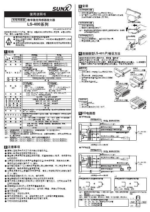
规格(注1):(注2):(注3):(注4):如果串联连接5~8个放大器为50mA ,如果串联连接9~16个放大器为25mA 。
连接器型LS-401(P )没有装备外部输入。
H-SP 模式改变为其他模式后,当使用防干扰功能、收集的数据库载入/保存功能或复制功能时,再打开电源。
连接器型LS-401(P )不附带电缆。
请按下述使用另售单触电缆 。
母电缆(4芯):CN-74-C1(电缆长1m ),CN-74-C2(电缆长2m ),CN-74-C5(电缆长5m )子电缆(2芯):CN-72-C1(电缆长1m ),CN-72-C2(电缆长2m ),CN-72-C5(电缆长5m )注意事项●●●●●●●●●●●●●●●●请确认在电源关闭状态下进行接线和增设作业。
请确认电源电压在额定范围内变化。
请注意如果使用的电压超出额定范围,或直接连接AC电源,传感器可能烧坏或损坏。
如果在该传感器附近使用产生噪音的设备(开关调节器,转换发动机等),请将设备机架接地端子(F.G.)接地。
由于超长距离(U-LG)模式的灵敏度比其他模式更高,所以更容易受外部噪音影响。
确保使用前检查周围环境。
如果电源是市场上零售的开关调节器,请务必安装电源的机架接地端子(F.G.)接地。
电源接通后短时间(约0.5秒)内,请勿使用。
请注意短路或负荷的错误接线可能烧坏或损坏传感器。
请勿将电线与高压线或电源线一起或在同一管内拉线,这可能会由于感应而引起故障。
连接器型LS-401(P )必须使用另售单触电缆。
0.3mm 2以上电缆可延长至100m。
但为减少噪音,使接线尽可能短。
请勿用在屋外。
避免灰尘、污垢和水蒸气。
请勿将传感器与水、油、油脂或有机溶液,如稀释剂等直接接触。
此传感器不可在有易燃易爆气体的环境下使用。
不可拆卸或改装传感器。
MC-LS400 No.8137-00非常感谢您购买SUNX产品。
请仔细、完整阅读此使用说明书以便正确、合理地使用此产品。
请务必妥善保管此说明书。
as400教程

as400教程AS/400教程第一章IPLIPL是AS/400的重要术语之一,它的全称是Initialize Program Laod,即初始程序装入,这是AS/400开机的一个重要过程。
要启动系统首先应打开系统电源开关,并执行初始程序装入(IPL),在IPL期间,将入系统辅助存储器装入系统程序,并检查系统硬件,当IPL完成时,将在所有可用的显示站上显示“注册”屏幕。
启动有两种方式,一种是自动(一般选用这种启动方式),另一种是手动。
启动区域一般选用B,启动区域另外还有A、D等;A表示从硬盘启动不用PTF,B表示从硬盘启动并用PTF;D表示从活动设备启动。
活动设备包括软盘、光盘和磁带机等。
改变IPL方式的方法有两种。
一种是通过主机面板来修改,有的机型对面板进行修改时需要插入钥匙。
另一种方法是通过修改系统值的方法来改变IPL的方式。
QIPLTYPE该系统值决定IPL的方式和类型。
它的可能值为0,1和2。
0--无人干预的IPL1--有人干预的IPL2--以Debug方式有人干预的IPL第二章用命令关机要关闭机器时在任何一个命令运行PwrDwnSys命令,即可关闭机器。
PwrDwnSys有以下几个参数:How to end . . . . . . . . . . . *CNTRLD *CNTRLD, *IMMEDDelay time, if *CNTRLD . . . . . 3600 Seconds, *NOLIMITRestart options:Restart after power down . . . *NO *NO, *YESRestart type . . . . . . . . . *IPLA *IPLA, *SYS, *FULLIPL source . . . . . . . . . . . *PANEL *PANEL, A, B, DHow to end是关机的方式,可选参数有两个:*CNTRLD和*IMMED,CNTRLD是CoNTRoLeD的简写,意思是“受控制的”,这一项只有选这一个参数接下来的那一个参数才起作用。
Nailor MLS-400 烟感与结合式火烟闸系统操作指南说明书
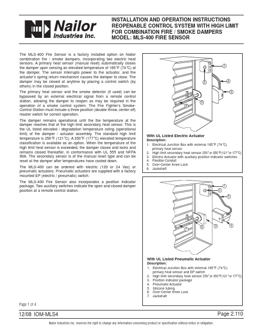
3. Place MCS in reopen (override) position. The damper will open. The closed (red) indicator light will go off and the open (green) indicator light will go on. Note: When the MCS is in the reopen (override) position, the smoke detector (if used) and primary heat sensor are bypassed. The damper will remain open even if the primary heat sensor has been activated. Do not leave MCS in reopen position.
Lorex 400 Series监控系统快速入门指南说明书
Set up Your Monitor FirStBaSic inStallation GuideSkill LevelIntermediate easy advancedHand ToolsHardwareRouterHi SpeedSkill Leveleasy Time Tools Skills - EasyUnder 10 Minutes*Hand ToolsPlug & Play connectors, On screen set up* Installation time may vary based on application and camera cablingBroadband Router and Com-LAN PORTSLAN (LOCAL AREA NETWORK)St e p 1Set up local ViewinG on Your pclocal computerSkill LevelIntermediateeasyadRouterTimeSkills - IntermediatePlug & Play connectors, On screen set upUnder 30 Minutes** Installation time may vary basedon applicationSkill Levelunder 30 minutes under 15 minutes under 60 minutes Hand ToolsHardware RouterHi Speed over 60 minutes HardwareComputer & Router** Minimum System Requirement: Windows XP, Pentium IV, 256MB Ram (512MB Recommended), 200MB Storage, Internet, DSL or Cable ModemBaSic inStallation GuideSt e p 2H O M E & B U S I N E S S S E C U R I T YSet up local ViewinG on Your pclorex client Software - local configuration:(on your local computer)From the Lorex Client Software - Local Configuration screen (as shown in Step 7), select the new Group you created using the drop down menu (1) and press the CONNECT button (2) to connect to the LOCAL LIVE site.Basic Installation GuideCONNECT BUTTON126LOCAL LIVE SITEOFFICESt e p 2C o nt i n u e dSet up internet reMote SecuritYMonitorinG123Timeunder 30 minutesunder 15 minutes under 60 minutes over 60 minutesSkill LevelIntermediateeasy advancedRouterTime Hardware Skills - Advanced60 Minutes Computer & Router*Basic Computer Skills,Router Port Forwarding* Installation time may vary basedon applicationSkill Levelunder 30 minutesunder 15 minutes under 60 minutesHand Tools HardwareRouterHi Speedover 60 minutes* Minimum System Requirement: Windows XP, Pentium IV, 256MB Ram(512MB Recommended), 200MB Storage, Internet, DSL or Cable ModemreMote ViewinG inStallation Guide S te p3enable ddnS Settings:Set the ddnS Settings:1. Scroll down to the DDNS SERVER within the NETWORK menu and press ENTER.2. Enter the USER ID sent to you in theREGISTRATION CONFIRMATION EMAIL.3. Enter the DOMAIN NAME sent to you in the REGISTRATION CONFIRMATION EMAIL () leaving out the part of the URL.4. Enter your PASSWORD (1234 by default).5. Click the DDNS Status button - A SUCCESS message will appear if the settings are correct.6. Scroll to OK button and press ENTER to accept.7. On the SYSTEM menu screen scroll down to APPLY and press ENTER.8. The system will now ask you to RESTART. Click OK.On the NETWORK menu, use the DOWN arrow key to navigate to DDNS. Highlight DDNS checkbox by pressing ENTER and press the UP arrow key to put a check mark in the DDNS checkbox. Press ENTER to accept settings.COMPUTER - NOT INCLUDEDinstall Software:(on your remote computer*)Insert the Lorex Client Software CD into your remote computer’s CD ROM drive and proceed with installation.lorex client Software:(on your remote computer*)Follow the installation screens to complete Lorex Client Software installation.lorex client Software:(on your remote computer*)Close the CD Menu Screen. A Lorex Client icon and a Lorex Player icon will appear on your desktop.run the lorex client Software:(on your remote computer*)Double-click the Lorex Client icon on your desktop to run the program.Set up internet reMote SecuritY MonitorinGon your For Lorex Client Application Software Requirements, please refer to page 8 of this guide.*For viewing your system from a remote locationlorex client Software - local configuration:(on your remote computer*)From the Lorex Client Software - Local Configuration screen (as shown in Step 13), select the new Group you created using the drop down menu (1) and press the CONNECT button (2) to connect to the REMOTE* LIVE site.CONNECT BUTTON12Set up internet reMote SecuritY MonitorinG6REMOTE* LIVE SITE*For viewing your system from a remote locationFor other remote access viewing features, please consult the Lorex Client Software Manual.OFFICEMonitor power SaVinG tipSystem Setup Menu:Click the SETUP button from the front panel of the monitor (or the remote control) to enter SYSTEM SETUP screen and select the SYSTEM SETUP and ENTER to go to the MAIN MENU.MONITOR FRONT PANEL - SETUP BUTTONMain Menu:In the MAIN MENU screen, select DISPLAY and press ENTER. Use the down arrow key and select SCREEN SAVER menu and ENTER to activate the SCREEN SAVER menu options.Screen Saver Menu:Auto Brightness:Adjust Brightness by highlighting and press-ing ENTER, then use the DOWN and UP arrow keys to adjust time.Press ENTER when complete.Main Display OFF:Enable this option by selecting ON. Set time on the‘FROM’ and ‘TO’ fields to determine the times you want the Main Display OFF.it’S all on tHe weBFor detailed setup information, please refer to your user’s Manual. Foradditional information about determining your ip address, configuring yourrouter, and port forwarding, please visit our website andclick consumer Guides Section or view guides from the lorex client Softwarecd included with your system.The Lorex Client software (included with the Observation System) has the following installation requirements.Minimum System requirements:。
WKLF-400无刷同步电动机微机励磁装置用户手册
WKLF-400无刷同步电动机微机励磁装置用户手册概述WKLF-400系列微机控制无刷同步电动机励磁系统是北京前锋科技有限公司研发的最新代无刷同步电动机励磁产品,其核心控制单元为Excitrol-400型做机控制同步电动机励磁调节器。
该系列的标准型产品型号为阪LF-402,配置双套 Excitrol-400励磁调节器:具有双套调节器自动跟踪和故障自动切换(调节器双冗余〕的技术性能。
如用户要求,亦可选配双套功率单元,主通道功率单元故障能自动切换至备用通道。
该系列的旋转励磁系统电气配置完全相同。
Excitrol-400励磁调节捧为结构独立的控制单元,其功能涵盖了励磁系统所有测量、控制、调节与保护:如F阳脉冲形成、模拟量测量、接点量开入开出、参数整定与励磁调节、软硬件故障监测、双~l通讯、后台i且讯、与PC机或液晶操作面板通讯等等。
采用双调节器配置时双机只通过CAN 通讯电缆连接,无任何公用部分,真正做到百分之百软、硬件冗余。
采用Exci trol-400励磁调节器只需另外配置励磁功率单元、人机操作面板及简单的操作指示元件即可构成整套静态励磁系统,各部分功能明确,结构简洁。
Excitrol-40Q励磁调节器采用具有超大规模集成度的32位嵌入式DSP处理器做为核心控制单元,其150MHz的主时钟频率足以应对任何复杂的快速运算:Excitrol-400励磁调节器内部儿乎所有模拟量测量均采用快速傅立时变换(FFT) 运算,具有极高的抗工业现场干扰能力o本系列的旋转励磁系统沿用WKLF-41型的旋转睛磁系统,有着多年的高可靠运行业绩,各功能模块均通过了南阳防爆电气研究所国家防爆电气产品质量检测中心的防爆检测,并取得防爆合格证。
本系列的旋转励磁系统具有滑差检测、准角判断环节、零压计时投励环节以及启动回路控制及监测功能,彻底解决了励磁系统可能出现的起动脉振、投励i骨差捕捉不到、投励冲击、运行中起iii)电阻发热等问题:并使系统具备失步保护和不被载自动再同步功能。
Vigilohm IM400 IM400L 设备安装与使用指南说明书

Quick Reference Guide7EN02-0417-0207/2020Commissioning Guide for Vigilohm IM400/IM400LElectrical equipment should be installed,operated,serviced,and maintained only by qualified personnel.No responsibility is assumed by Schneider Electric for any consequences arising out of the use of this material.About this guideThis guide explains about the commissioning procedure of Vigilohm IM400/IM400L.Throughout this guide,the term “device”refers to Vigilohm IM400/IM400L.All differences between the models,such as a feature specific to one model,are indicated with the appropriate model number or description.For detailed installation and operating instructions,including safety messaging,read the device instruction sheets and user manual.Document ReferenceSetting date and timeOn first power up,set the date and time.Setting date and time ensures proper timestamps for the logs and trends.1.Turn on the power supply.Auto-test begins in the device.Wait for 10seconds for auto test to complete.•If auto-test passes,the INSULATION screen displays a resistance value.An example INSULATION screen is:•If auto-test fails,an error code is displayed.Schneider Electric 35rue Joseph Monier 92500Rueil Malmaison –FrancePhone:+33(0)As standards,specifications,and design change from time to time,please ask for confirmation of the information given in this publication.©2019–2020.All rights reserved.Commissioning Guide for Vigilohm IM400/IM400L Setting date and time2.Press theflashing button.NOTE:The clock icon flashes to show that date and time needs to be set. The DATE/TIME screen displays.DATE / TIME3.Setthe date and time using thecontextual menu buttons and.4.Press button to save the date and time.A message Saved displays.DATE / TIMEThe Insulation screen displays a resistance value.An example INSULATION screen is:Configuring network parameters Commissioning Guide for Vigilohm IM400/IM400LConfiguring network parameters1.Navigate to Menu >Settings >Network .The NETWORK screen displays.NETWORK 2.Modify the parameters value as per the following table:NOTE:Use the contextual menu buttons to modify the parameters value.Commissioning Guide for Vigilohm IM400/IM400L Configuring insulation alarm parameters Configuring insulation alarm parameters1.Navigate to Menu>Settings>Ins.Alarm.The INS.ALARM screen displays.INS. ALARM2.Modify the parameters value as per the following table:NOTE:Use the contextual menu buttons to modify the parameters value.Configuring input output parameters Commissioning Guide for Vigilohm IM400/IM400LConfiguring input output parameters1.Navigate to Menu >Settings >I/O Config .The I/O CONFIG screen displays.I/O CONFIG 2.Modify the parameters value as per the following table:NOTE:Use the contextual menu buttons to modify the parameters value.Commissioning Guide for Vigilohm IM400/IM400L Configuring ModbusparametersConfiguring Modbus parameters1.Navigate to Menu >Settings >Modbus .The Modbus screen displays.MODBUS2.Modify the parameters value as per the following table:NOTE:Use the contextual menu buttons to modify the parameters value.。
- 1、下载文档前请自行甄别文档内容的完整性,平台不提供额外的编辑、内容补充、找答案等附加服务。
- 2、"仅部分预览"的文档,不可在线预览部分如存在完整性等问题,可反馈申请退款(可完整预览的文档不适用该条件!)。
- 3、如文档侵犯您的权益,请联系客服反馈,我们会尽快为您处理(人工客服工作时间:9:00-18:30)。
2. 本产品设计采用低功率半导体激光,测试及检验均符合全世界最严格 的安全标准 (3B激光产品) ,且产品本身已采取相当的保护措施避免激 光外漏,当操作时请带上墨镜且在任何情况下均不可直视激光光源, 以免造成不可挽回的视神经伤害。 3. 产品设计本身有保护机制防止液体被吸入控制主机内部,造成主机的 故障!并请随时检查气电管端的空气滤芯器是否有阻塞现象,空气滤 芯器的阻塞将导致无法吸附或激光外漏之危险。 4. 产品本身具有自动吸附功能, 最大的吸附力控制在 -300mmHg以下。 以 确保不会造成人体的伤害。唯各人因素不同在使用初期请事先调整合 适的吸附力。 5. 激光治疗时间不可同一位置连续治疗超过 15 分钟! 6. 激光输出模块:660nm是可见红光,808nm是不可见光! 确记:在任何 情况下均不可直视激光光源! 7. 注意:若不按此规定使用控制或调整装置或执行各步操作,就可能引 起有害的辐射照射。 8. 注意:检修及校正工作执行,必须为本公司技术人员或经由本公司训 练且授权的技术人士才能执行之。 9. 注意:不使用本设备时,务必将锁匙取走,交由专业人士妥善保管, 以防未经许可的使用。 10.注意:使用本设备时,必需配戴护目镜,以保持对眼睛的保护。 11.注意:必须避免使用易燃麻醉剂或氧化性气体如氧化亚氮(N2O)和氧 气。应该注意用于清洗和消毒的溶液及内部气体点燃的危险。 12.电气安全分类:I类BF型,不防进液封闭的普通设备,非AP或A PG类设备,连续运行的设备。
2
2
警 告
பைடு நூலகம்安全事项
以下这些数据,关系到设备的使用效率和安全,请务必仔细阅读: 1. 本设备已严密测试并且符合 EN60601 设备电磁兼容之相关标准。 本设 备在商业环境下运作时,将提供合理的保护以防有害的干扰。然而操 作本设备仍有可能会产生些微的电磁能量干扰,于此情形状况下使用 者须自行采取有关步骤,以免除干扰。(如果您使用其它的医疗设备有干
4 4
目录
前言 ............................................................................................................................................................................................. 6 第一章 产品介绍 ....................................................................................................................................................................... 7 1.1 功能简介 ......................................................................................................................................................................... 7 1.2 基本规格表 ..................................................................................................................................................................... 7 1.3 系统特性 ......................................................................................................................................................................... 7 1.4 主机连接端口说明 ......................................................................................................................................................... 8 1.5 按键说明 ......................................................................................................................................................................... 9 1.6 符号说明 ....................................................................................................................................................................... 10 1.7 使用环境 ....................................................................................................................................................................... 10 第二章 操作说明 ..................................................................................................................................................................... 11 2.1 基本操作说明 ............................................................................................................................................................... 11 2.2 激光参数调整 ............................................................................................................................................................... 13 2.3 系统主选单 ................................................................................................................................................................... 14 2.4 快速模式 ....................................................................................................................................................................... 15 2.5 紧急停止 ....................................................................................................................................................................... 17 2.6 电池电力不足 ............................................................................................................................................................... 17 2.7 系统功能设定 ............................................................................................................................................................... 18 2.8 系统操作示意图 ........................................................................................................................................................... 19 2.9 罩杯及激光说明 ........................................................................................................................................................... 20 第三章、常见问题及故障排除 ............................................................................................................................................... 21 第四章、售后服务保证书 ....................................................................................................................................................... 22 第五章、技术规格 ................................................................................................................................................................... 23 第六章、安全控制机制 ........................................................................................................................................................... 24 第七章、设备清洁方式 ........................................................................................................................................................... 25 第八章、产品标示说明 ........................................................................................................................................................... 26 8.1 产品标示一:产品规格卷标 ....................................................................................................................................... 26 8.2 产品标示二:警示卷标(防止电击保护等级-型式 BF 设备) ............................................................................. 26 8.3 产品标示三:警示标签(注意:参考随附文件) ................................................................................................... 26 8.4 产品标示四:警示标签(注意:激光波长,输出功率及勿直视激光警语) ....................................................... 26
