欧马可康明斯3.8全车电器原理图
欧马可康明斯车型服务手册

欧马可康明斯车型服务手册编制:杨宪坤审核:刘文审定:蔡保荣批准:王玉荣北汽福田汽车股份有限公司北京欧马可轻型汽车厂二〇一〇年一月第一部分欧马可康明斯车型结构特点综述欧马可作为福田高端轻卡品牌,匹配了与康明斯全球同步开发的ISF3.8高速高效、低噪低耗的高品质发动机,该款车型的研发是在数位海归专家的指导下,综合中英美德四国专家团队经验,耗资1.2亿,历时3年,链合全球先进技术资源,自主研发设计的、具有完全自主知识产权,面向国内和国际市场开发的新一代产品。
该系列产品集欧美卡车的动力性与安全性,日本卡车的轻巧精细与经济,以及中国的成本控制优势于一身,是一款纯粹的驱动世界的高效轻卡。
该产品累计试装、试制车辆27辆,完成超过260万Km的试验里程,整车具有较高的可靠性和耐久性。
其主要结构特点如下:1、搭载全球技术领先的康明斯动力,结构紧凑(发动机轮系仅为1根皮带,自动涨紧),大功率(105KW,115KW,125KW),低油耗(15L/100Km),低噪声(驾驶员耳旁噪声78dB);2、标配646/651/6G120,选装ZF E2407变速箱,6G120全铝壳体,双锥面同步器,操纵轻便,齿轮磨齿,有效降低啮合噪声;3、采用SCR后处理系统,整车达到国IV排放标准,具有欧V潜力;4、采用ABS制动系统,极大提高制动安全性;5、步进电机式驱动指针和LED照明、报警,指示精度高,分度均匀,响应速度快,无抖动现象,可靠性高,增加发动机转速表及尿素表(国IV),实用性更强;6、定速巡航功能,利于高速行驶或市政环卫车,停止为PTO功能,利于专用改装车。
第二部分各子系统技术状态及注意事项一、发动机1、图片示例序号项目单位参数1 发动机铭牌型号ISF3.8s4141 ISF3.8s4154 ISF3.8s41682 发动机型式直列、水冷、四冲程、增压、中冷发动机3 气缸数,缸径×冲程mm 4-102x1154 排量(L) 3.765 额定功率kW(r/min)105/2600115/2600125/26006 最大扭矩N-m(r/min)450/1200-2200500/1200-1900600/1300-17007 外特性最低比油耗g/ k w. h 2008 机油燃油消耗比0.159 无负荷时最高转速r/min 295010 怠速r/min 750±1011 起动性-10℃以上不带进气加热器/3次均成功-10℃到-25℃(带进气加热器)/3次均成功12 适应最高环境温度(℃)(℃)5013 润滑方式压力和飞溅复合式14 适应海拔高度(m)3146m以下功率不损失,以后每增加300m功率降低4%。
东风康明斯电控发动机故障案例分析—ppt课件

东风商用车公司市场销售总部
10 10
ECM常通电源的要求: 1、在接通电源总开关之前,确保4针电源接头完全插入,防止虚接; 2、在接通或断开电源总开关之前,应关闭点火锁; 3、ECM常通电源不得从车辆底盘上的其他电源处取电; 4、切断电源时必须先切断电源正极,不得先切断电源负极; 5、从蓄电池正极到ECM再连回蓄电池负极之间的整个电阻应小于0.04欧姆,电阻不符合 要求时,可以使用触针 2(接地)和触针 3(电源)。
CAN总线各接头出现虚接 常通电源接头虚接 开关电源电路中出现虚接 3、通过排查发现发现停机开关线束接头进水(离前轮较近),触针 腐蚀。 4、通过对触针除锈、防锈处理后,重新连接故障排除。
东风商用车公司市场销售总部
15 15
故障案例4 (东风天龙,ISLe 6缸,新车)
故障现象:改装厂改装后发动机不能启动,仪表报“仪表与EECU通讯故障”
故障分析及排除步骤: 1、首先检查电源电路:
45号开关电源为24伏,正常
常通电源为24伏,正常,但在插接四针接头时发现有调火现象,测量ECM四针接 头电源触针和回路触针的电阻存在短路现象(正常应为5~7千欧) , 则
判断ECM电源电路存在内部短路。 2、更换ECM,故障排除。 故障原因:改装厂在焊接时,未断开ECM的接头,焊接过程中烧坏ECM。
东风商用车公司市场销售总部
66
三、电控发动机电源电路的分析
东风商用车公司市场销售总部
77
1、东风天锦——ISDe
45号针电源为开关电源,为ECM提供点火信号。常通电源通过ECM上的一个四针接 头为ECM提供主电源。
欧马可ISF3.8&ISF2.8发动机介绍2011.2.26(驾驶员培训资料)

维修保养注意事项
油底壳采用复合材料(塑料)制成,不能超 负荷承重、不耐高温(不可用火烤)。
加装机油加热器时,必须选用合适的油底壳 (即承重能力加强的)。 机油的选择:CF-4及以上级。 推荐使用多级机油。
观察机油油位、加注机油时,发动机需处于 水平位置、并且处于停机状态。
机油滤清器需要预加注。 准确安装活塞冷却喷嘴,否则活塞会因没有 机油的冷却润滑而导致拉缸。 运行发动机至60℃,停机后,方可排放机油。
欧马可配福康发动机维修保养注 意事项
欧马可服务管理部 2011.2
目
录
欧马可ISF3.8&ISF2.8车型使用及维修保养注意事项
1、欧马可配康明斯发动机车型的结构特点 2、整车部分使用及维修保养注意事项
3、发动机电控部分使用注意事项
欧马可ISF3.8&ISF2.8车型使用及维修保养注意事项
1、欧马可配康明斯发动机车型的结构特点
出于对燃油系统的保护,不要对细滤进行预注。
按压手油泵对细滤进行预注,对于未预注粗滤的按压约140到150 次、预充注过的粗滤的按压20 到60次。 对于有些时候燃油泵不泵油,只需用手按压几次燃油泵上的黑色按钮即可。
对于ISF2.8发动机而言,只有一级过滤(只有一个燃油滤清器),因此为保证进入燃油系统的燃 油的清洁,不需要预加注滤清器。
续上页
⑤ 故障诊断控制:系统实时对发动机的各个参数进行监测,进行故障诊断并输出故障码,以 便于维护发动机并提高车辆行驶安全性。当系统检测到故障时将点亮仪表板上的发动机故 障指示灯,告知驾驶人员检查发动机。
工作原理简介(康明斯)ppt课件

23.05.2020
.
19
发动机的基本结构 冷却系统
二。冷却系统构成
构成:由散热器、水泵、汽缸体水道、汽缸盖水道、出水
管、节温器、水滤器、中冷器、机油冷却器,以及选用件
23.05.2020
.
12
燃油滤清器
燃油滤清器的功能是让油在进入油泵以前滤出杂质。NH和K 系列发动机常用是“旋装式”滤清器,这类滤清器是用纸做滤 芯 , 滤 芯 的 过 滤 能 力 为 大 于 6微 米 的 杂 质 。 滤 清 器 在 工 作 时 , 终 究会因杂质堆积而形成阻碍,从而降低发动机的功率。所以滤 清器的阻力不能超过规定值,以下有两种方法可以防止这点。
.
32
23.05.2020
.
6
康明斯发动机的基本结构
发动机工作循环
压缩冲程:
在进气冲程的终了,进、排气门关闭,活塞开始上行,压 缩燃烧室里的空气,使空气的温度升高到柴油的燃点温度以上 压缩比为:14.5----15.5。汽油机压缩比较小。
作功冲程:
压缩冲程接近终了时,由喷油器喷入适量的柴油并燃烧(汽油 机由火花塞点火〕。燃烧后的膨胀气体推动活塞向下运动,通 过连杆使曲轴旋转而输出动力。这时,进、排气门关闭。
16
康明斯发动机的基本结构 润滑系统的组成
23.05.2020
.
17
康明斯发动机的基本结构 润滑系统的组成
23.05.2020
.
18
康明斯发动机的基本结构
冷却系统
一. 概述
1. 热量产生:喷入柴油机燃烧室的柴油,燃烧产生大量的热量; 2. 热量分配: 约三分之一通过活塞及连杆机构,转换成机械能对外作工; 约三分之一由排气排入大气; 约三分之一冷却系统散失; 3. 康明斯发动机冷却方式为循环水冷式,它与其他发动机冷却系统具有相同功
康明斯电控基础及INSITE培训PPT课件
• Sensors/传感器输入 • Switches/开关输入
• Electronic Control Module or ECM/电子控 制模块
• microprocessor/ 微处理器 • Memory/存储器
• Output device/输出设备
• Actuators/执行器
• 传感器的电阻值范围在500到40千
• The resistance of sensors is inversely propertional to temperature,the change in resistance is not liner
• 传感器的电阻与温度成反比,这种变化 不是线性的
• 怠速有效传感器
康明斯电控基础及INSITE培训
Switch/开关
• Single Pole-Single Throw Switch • 单刀单掷开关
• Single Pole-Double Throw Switch • 单刀双掷开关
康明斯电控基础及INSITE培训
Switch/开关
• Double Pole-Single Throw Switch • 双刀单掷开关
• Combination sensors • 组合式传感器
• Fluid level sensors • 液位传感器
• Speed and position sensors • 速度及位置传感器
康明斯电控基础及INSITE培训
Temperature Sensors
温度传感器
• Include/包括:
康明斯电控基础及INSITE培训
Symbol of Switches 开关的符号
康明斯柴油机的总体结构及工作原理

康明斯柴油机的总体结构及工作原理1.康明斯柴油机的总体结构及工作原理康明斯柴油机为四冲程高速柴油机。
它由进气、压缩、做功和排气四个冲程完成一个工作循环。
1.1.曲柄连杆机构曲柄连杆机构是柴油机进行工作循环、完成能量转换的主要机构,它包括机体组、活塞连杆组、曲轴飞轮组三大部分。
1.1.1.机体组的主要组成与功用(1)机体组主要由汽缸体、曲轴箱、汽缸套、汽缸垫、油底壳和汽缸盖等组成。
(2)机体组是柴油机的骨架,是安装所有零部件与保证运动零件正常运转的基础。
康明斯NTA855型柴油机汽缸体为灰铸铁铸造,结构形式为整体龙门式,即汽缸体与上曲轴箱连为一体,它的外部和内部安装着柴油机的所有零件。
它的上面有汽缸盖封闭汽缸上部,并与活塞顶部构成燃烧室。
它的下部为下曲轴箱和油底壳连为一体的油底壳。
NTA855型柴油机的汽缸套采用单体可拆卸湿式缸套。
这种湿式缸套外圆表面直接和冷却水相接触,冷却效果好。
它采用两缸一盖,每个缸均采用四个气门。
汽缸盖一侧有进气道,两缸的进气道共用一个进气口并与一个单独的进气管相通。
缸盖另一侧有排气道,分别通过各缸的排气口与排气歧管相连。
汽缸盖上面装有气门导管、丁字压板、导杆、气门弹簧等。
1.1.2.活塞连杆组的组成与功用(1)活塞连杆组主要由活塞、活塞环、活塞销、连杆及连杆轴承等零件组成。
(2)活塞与汽缸盖、汽缸壁等共同组成燃烧室,承受气体压力并通过活塞销传给连杆,以推动曲轴旋转。
康明斯NTA855型柴油机的活塞由耐热性和耐磨性良好的共晶硅铝合金制成。
有较高的抗疲劳强度、导热性好等优点。
它属于直接喷射式燃烧室,在活塞顶部有ω形凹坑。
NTA855型柴油机有三道气环、一道油环。
第一道气环断面为梯形,称为筒面梯形环,由可锻铸铁制成。
第二道气环由球墨铸铁制成,断面为梯形,扭曲形及环外表面有2°锥角的组合形。
第三道气环也由球墨铸铁制成,断面为梯形扭曲形与缸壁接触面呈2°锥角。
油环为合金铸铁制成,两面有较大的倒角,与缸壁相接触的环外表面镀铬,在油环的内面安装有螺旋弹簧胀圈。
ELECTRIC(康明斯电器系统)

应用工程培训
图8- 只有当断油阀电流小于5A时,才可以直接接到点火开关(如康明 斯PT泵和BOSCH转子泵断油阀)
Electrical System 电器系统
Requirements 安装要求--控制系统
应用工程培训
图9- 康明斯B系列发动机断油阀吸拉线圈最低工作电压
Electrical System 电器系统
Guidelines 设计指导
应用工程培训
发电机的选择
因为发电机在不同转速的输出电流不同,所以,选择发电机时一定 要考虑不同转速下所有附件需要的最大可能电流,包括怠速、额定 转速、最大扭矩转速等; 发电机的输出电流应大于所有附件消耗电流的15%给起动马达充电 。
Definitions 定义
应用工程培训
Cold Cranking Amps (CCA) 冷起动电流
定义见SAE J537。-18℃,蓄电池在短时间内能输出的的最大 电流值。 串联蓄电池组:总CCA不增加 并联蓄电池组:总CCA=单个CCA X 电池数
Reserve Capacity (RC) 储备容量
康明斯发动机应用工程培训 康明斯发动机应用工程培训
Electrical System 电器系统 Electrical System 电器系统
Electrical System 电器系统
Contents 内容
应用工程培训
内 容 定义 安装要求 设计指南 评审程序 常见问题
Electrical System 电器系统
60
40
20
0
0
1000
2000
3000
4000
5000
6000
3.8发动机电路图EGR(欧IV) 国四

F
J2
J1
87 63 62 13 14 38 50 49 2 26 1 25 74 73
2
1
C20 2 3 1 4 C21 2 3 1 4
J6
VSENSOR_1-OEM_SENSORS
VSENSOR_1-SENSOR_RETURNS
D E
D E
E
C SWITCH_RETURN C SWITCH_RETURN
START BATT ACC
C6 C6CAP 008 1939_(+)_(PRIVATE) GN 0.75 mm2 AA 009 1939_(-)_(PRIVATE) GN 0.75 mm2 BB CC
G
1 2
KYSW
1 2 2 1
68 69 92
C7 010 VSENSOR_4-SENSOR_RETURNS_#1 BK 0.75 mm2 1 011 FUEL_PRESSURE BE 20 mm2 2 012 VSENSOR_4-ENGINE_SENSORS_#1 RD 0.75 mm2 3 C8 180 VSENSOR_4-ENGINE_SENSORS_#1 RD 0.75 mm2 1 F 176 VSENSOR_4-SENSOR_RETURNS_#1 BK 0.75 mm2 2 Y 015 AMBIENT_AIR_PRESSURE_(AAP) BE 0.75 mm2 3 C9 016 INTAKE_MANIFOLD_PRESSURE_(TMAP) BE 0.75 mm2 1 017 VSENSOR_4-ENGINE_SENSORS_#1 RD 0.75 mm2 2 018 INTAKE_MANIFOLD_TEMPERATURE_(TMAP) BE 0.75 mm2 3 019 VSENSOR_4-SENSOR_RETURNS_#1 BK 0.75 mm2 4 C10 020 VSENSOR_4-ENGINE_SENSORS_#1 RD 0.75 mm2 1 021 VSENSOR_4-SENSOR_RETURNS_#1 BK 0.75 mm2 2 022 ENGINE_SPEED_BACKUP_SENSOR_(CAM) BE 0.75 mm2 3 C11 023 VSENSOR_3-ENGINE_ESS RD 0.75 mm2 1 024 VSENSOR_3_ESS_RETURN BK 0.75 mm2 2 025 ENGINE_SPEED_MAIN_SENSOR_(CRANK) BE 0.75 mm2 3
技能培训课件-康明斯发动机电控基础介绍

康明斯发动机电控基础介绍
主要内容:
▪ 发动机电子控制介绍 ▪ 发动机采用电控系统的优势 ▪ 发动机电控系统的主要控制
内容及组成
▪ 康明斯电路图 ▪ 康明斯电控系统线束与插头
2
发动机电子控制介绍
3
发动机电控系统概述
和传统机械控制的发动机相比,电控发动机通过 一个中央电子控制模块(ECM)来控制和协调发动机 的工作,ECM就像人的大脑一样,通过各种传感器和 开关实时监测发动机的各种运行参数和操作者的控制 指令,经过计算后发出命令给相应的执行元件,如喷 油器等,实现对发动机的优化控制。控制系统通过精 确控制喷油时刻和喷油量,以达到降低排放和提高燃 油经济性的目的。
决定输出信号
通信
输出设备:
执行ECM的控制命令
喷油器电磁阀 报警指示灯 等等
23
电子控制模块(ECM)
▪ ECM是整个控制系统的核心。ECM内部有存储器,
存储控制系统运行的程序。这些程序可以通过服务软 件擦除重写。
▪ ECM接收传感器或其他装置的输入信息,给传感器提
供基准电压(一般为5V);将输入的信息转变为微控制 器所能接受的信号。
▪ 在控制系统中,ECM不仅用来控制燃油喷射系统,同
时还具有怠速控制、排放控制、进气控制、增压控制、 自诊断、失效保护和备用控制系统等多项控制功用。
25
电子控制模块(ECM)
由于燃油系统多样性,康明斯有多种型号的ECM 用在不同型号发动机上。ECM零件号代表了ECM硬 件。对同一平台的发动机,由于应用场合的不同, ECM会有所不同。对车用和工程机械应用,通常 ECM的型号和零件号是一样的,但采用不同的标定软 件。对同一型号的发动机,在相同的应用场合,ECM 内的控制软件依然有所不同,这是由于发动机的功率, 适应的排放法规的不同等原因造成的。在重新标定 ECM时必须注意选择合适的标定软件,这些不同的标 定软件是通过ECM Code号来区分的。ECM Code代 表了ECM中的软件。
康明斯伟力柴油发电机_图文_图文

发电机组结构及基本原理
康明斯/伟力柴油发电机
柴油发电机组由柴油机、发电机、控制系统三大部分及其他辅助设备组成
康明斯/伟力柴油发电机
一、柴油发电机工作原理
简而言之,就是柴油机驱动发电机运转。
在汽缸内,经过空气滤清器过滤后的洁净空气与喷油嘴喷射出的高压
雾化柴油 充分混合,在活塞上行的挤压下,体积缩小,温度迅速升高,
1、将充电机断电 2、做好安全措施 3、将蓄电池负极一端接线拆除。(操作中注意安全措施)
康明斯/伟力柴油发电机
十四、柴油发动机维护保养:
结合宝鸡站设备维护保养大表进行维护:
3、控制系统 控制系统作用:柴油发电机组工作过程的监示和控制,包括柴油机工
作参数的测量显示、发电机电量测量显示、发电机输出主回路控制、柴油 机、发电机保护及发电组过程控制。 按结构分:(a) 一体化控制箱(b) 分体控制屏 按功能分:(a)手动型(b)自动化型(c)并联型
二、部件介绍
康明斯/伟力柴油发电机
柴油发电机操作前的检查和准备:
在手动起机或把机组放在自动起动前,应作以下工作: 控制屏各项参数检查。 发电机组的接地检查。 机油油位检查,油位应在油尺的高低标记线之间。 散热水箱水位应符合要求,水箱水位低则添加冷却水。 通风散热检查。确保机房进出风畅通无阻,进出通风量符合机组冷却要求。 排气管检查。波纹管没有弯曲变形,排气管无泄漏,排气畅通。 燃油管路、油箱检查。燃料油注油阀关闭,燃油管路畅通,油箱液位在规定的范围内。 电池检查。电池电压符合机组起动要求,不能低于24V,充电机工作正常。 检查所有连接管件紧固无渗漏;传动皮带、风扇等传动部件的护盖是否盖好。
康明斯发电机3100系统介绍
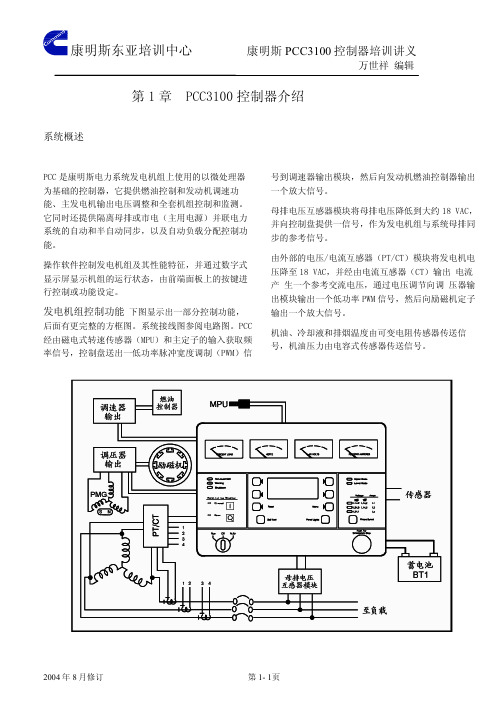
色蓝 色紫 色黑 色黄/绿 色灰 色白 色棕 色红 色橘 色黄 �线接 9J 。�器 。配 匹流电出输的组机电发与器感互流电证保须必�作 操确正了为�器感互流电的定特有均组机套每�外另 。板路电器感互流电/压电的配匹组机电发 与择选须必�作操确正了为�型类种三有共板路电本 9J 8J 。板路电拟模至出输�时载满�CAV 56.1 成换转 �时载满�流电出输的培安 55.0 器感互流电将时同 �板路电拟模给供�CAV 81 成换转压电出输机电发 将板路电该�内箱件附于装板路电器感互流电/压电
21SD 11SD 01SD 9SD
8SD 7SD 6SD 5SD 4SD 3SD
2SD
1SD �态状
列下示显别分�管极二组 72 有共板路电面界户用
�DEL�管极二
。4J 的上�33A�板路电拟模到接连 5J 4J 3J 2J 1J
�下如明说别分�件插接组 5 有板路电面界户用
件插接
。型类种二用联并 非和用联并有板路电该。用使号信出输或入输户 用供点接供提时同�号信流电和压电测检以�上 板路电器感互流电/压电到接连板路电面界户用
�丝险保式换更可种二有含板路电面界机动发
丝险保
。�MCG�块模制控组机电发到接连 。�MCG�块模制控组机电发到接连
7J 6J
�13A�板路电面界机动发
辑编 祥世万
义讲训培器制控 0013CCP 斯明康
心中训培亚东斯明康
页6 -1 第
订修月 8 年 4002
板路电面界机动发
辑编 祥世万
义讲训培器制控 0013CCP 斯明康
件插接
�23A�板路电字数
辑编 祥世万
义讲训培器制控 0013CCP 斯明康
心中训培亚东斯明康
康明斯电喷发动机原理 ppt课件

11
注:如果发动机的铭牌模糊不清,在发动机缸 体的机油冷却器壳体顶部可以找到发动机生产 序号。
2、喷油泵铭牌
康明斯Bosch喷油泵铭牌位于喷油泵顶部。
铭牌包含以下信息:
▪ 燃油泵生产序号
▪康明斯零件号
▪工厂代码
▪BOsch零件号
▪日期代码
ppt课件
12
3、ECM铭牌
电子控制模块(ECM)的铭牌显示ECM的信息 以及的ECM的编程方法,铭牌位于ECM上。 ECM铭牌提供如下信息: ▪ ECM零件号(PN) ▪ ECM生产序号(SN) ▪ ECM数据代码(DC) ▪发动机生产序号(ESN) ▪ ECM代码:指示ECM的软件 注:与康明斯特约维修站联系时,必须提供ECM 代码.
1、发动机铭牌
发动机铭牌提供有关发动机的详细信息。发
动机的生产序号和控制零件目录(CPL)用于订 购零件和维修。
当与康明斯授权的维修站联系时,需提供以 下发动机数据,当查找服务零件时,铭牌 上的信息是必不可少的。
1) 发动机生产序号
2) 控制零件目录编号(CPL)
3) 型号
4) 额定功率和转速
ppt课件
ppt课件
6
三、电控共轨系统的组成
电控高压共轨式燃油系统的基本组成如图所示。从功能方面分析,电控共轨系统 可以分成两大部分:
1.控制系统·
电控共轨系统可以分成三大部分:传感器、计算机和执行器。计算机是电控共轨燃油系
统的核心部分。
根据各个传感器的信息,计算机进行计算、完成各种处理后,求出最佳喷油时间和最合
4、冷却系统参数
▪冷却液容量(仅限于四缸发动机)………………………8.5升
▪冷却液容量(仅限于六缸发动机)………………………10升
康明斯发动机电路图:ISBe
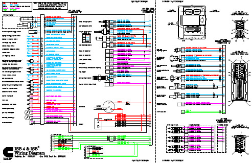
FUEL RAIL PRESSURE SENSORT orque=3N•m[27in-lb]Pressure(mPa)Pressure[psi]Voltage(VDC) 000.50405801 1.397010153 2.0610014504 2.7214020305 3.6118026107 4.50ACCELERATOR PEDAL(IVS,ISS,&APS)Idle Validation Circuit Resistance:For ON and OFF-IDLE statesISS-MAX Closed Circuit Resistance<125ΩISS-MIN Open Circuit Resistance>100kΩACCELERATOR PEDAL and REMOTE ACCELERATOR Accelerator Position Sensor Coil Resistance:Between supply and return wires•2000to3000ohmsBetween supply and signal wires(released pedal)•1500to3000ohmsBetween supply and signal wires(depressed pedal)•200to1500ohmsNOTE:Released resistance minus depressed resistance must be1000ohms.FAULT CODE INFORMATIONFAULT CODE LAMP PID(P)SID(S)FMISPN(S)FMI REASON EFFECT(Only when fault code is active)111 Red S2541262912ECM internal hardware error.Possible no effect or engine will run rough or notstart.122 Y ellow P10231023High voltage detected at the intake manifold pres-sure sensor signal pin28of the engine harness.Engine can derate to no-boost fueling.123 Y ellow P10241024Low voltage detected at intake manifold pressuresensor signal pin28of the engine harness.Engine can derate to no-boost fueling.131 Red P09130913High voltage detected at accelerator position signalpin83of the OEM harness.Engine idles when idle validation switch indicates idleand ramps up to a default set speed when the idlevalidation switch indicates off-idle.132 Red P09140914Low voltage detected at accelerator position signalpin83of the OEM harness.Engine idles when idle validation switch indicates idleand ramps up to a default set speed when idle vali-dation switch indicates off-idle.133 Red P02939743High voltage detected at remote accelerator positionsignal pin85of the OEM harness.Engine will not respond to remote accelerator input.134 Red P02949744Low voltage detected at remote accelerator positionsignal pin85of the OEM harness.Engine will not respond to remote accelerator input.135 Y ellow P10031003High voltage detected at oil pressure signal pin33of the engine harness.Default value used for oil pressure No engine protec-tion for oil pressure.141Y ellow P10041004Low voltage detected at oil pressure signal pin33ofthe engine harness.Default value used for oil pressure.No engine protection for oil pressure.143 Y ellow P100110018Oil pressure signal indicates oil pressure below thelow engine protection limit.Power and/or speed derate and possible engine shut-down if engine protection shutdown feature is en-abled.144 Y ellow P11031103High voltage detected at coolant temperature signalpin36of the engine harness.Default value used for coolant temperature.No engine protection for coolant temperature.145 Y ellow P11041104Low voltage detected at coolant temperature signalpin36of the engine harness.Default value used for coolant temperature.No engine protection for coolant temperature.146 Y ellow P110110Coolant temperature signal indicates coolant tem-perature has exceeded the engine protection limit.Power derate and possible engine shutdown if engineprotection shutdown feature is enabled.151 Red P110110Coolant temperature signal indicates coolant tem-perature has exceeded the engine protection limit.Power and/or speed derate and possible engine shut-down if engine protection shutdown feature is en-abled.153 Y ellow P10531053High voltage detected at intake manifold tempera-ture signal pin29of the engine harness.Default value used for intake manifold temperature.No engine protection for intake manifold temperature.154 Y ellow P10541054Low voltage detected at intake manifold tempera-ture signal pin29of the engine harness.Default value used for intake manifold temperature.No engine protection for intake manifold temperature.155 Red P105105Intake manifold air temperature signal indicates in-take manifold air temperature is above the engineprotection limit.Power and/or speed derate and possible engine shut-down if engine protection shutdown feature is en-abled.187 Y ellow S232410804Low voltage detected on the ECM voltage supplyline to fuel rail pressure sensor pin12of the engineharness.Possible low power.197 Y ellow P111111118Coolant level signal indicates coolant level has ex-ceeded the engine protection limit.Power and/or speed derate and possible engine shut-down if engine protection shutdown feature is en-abled.198 Mainte-nance S122416614Error detected on warning lamp circuit.Error couldbe open circuit,short circuit to battery or ground.Warning(yellow)lamp will not operate correctly.212Y ellow P17531753High voltage detected at the oil temperature signalpin35of the engine harness.Default value used for oil temperature.No engine protection for oil temperature.213Y ellow P17541754Low voltage detected at the oil temperature signalpin35of the engine harness.Default value used for oil temperature.No engine protection for oil temperature.221Y ellow P10831083High voltage detected at the ambient air pressuresignal(internal to the ECM).Possible black smoke.Engine protection system canbe affected.Altitude derate will not function.227 Y ellow S232310803High voltage detected on the ECM voltage supplyline to fuel rail pressure sensor pin12of the engineharness.Possible low power.234 Red P190190Engine speed signal indicates engine speed hasexceeded the overspeed limit.Fuel to injectors disabled until engine speed falls be-low the overspeed limit(3500rpm fault set,3200rpmbegin fueling).235 Red P11111111Coolant level signal at pin59of the OEM harnessindicates coolant level is low.Power and/or speed derate and possible engine shut-down if engine protection shutdown feature is en-abled.238 Y ellow S23246204Low voltage detected on the ECM voltage supplyline to the oil pressure sensor pin9of the engineharness.Default value used for oil pressure sensor connectedto this+5VDC supply and no engine protection foroil pressure.239 Y ellow S23236203High voltage detected on the ECM voltage supplyline to the oil pressure sensor pin9of the engineharness.Default value used for oil pressure sensor connectedto this+5VDC supply and no engine protection foroil pressure.241Y ellow P08420842Vehicle speed signal on pins56and74of the OEMharness has been lost.Engine speed limited to‘‘Max.Engine Speed withoutVSS’’.Cruise control,gear-down protection and theroad speed governor will not work.T rip informationdata that is based on mileage will be incorrect.FAULT CODE LAMP PID(P)SID(S)FMISPN(S)FMI REASON EFFECT(Only when fault code is active)244 Y ellow S23846234Error detected on one or more of the lamp circuits.Error could be open circuits,or short circuits to bat-tery or ground on any lamp except diagnostic lamp.Lamp will not come on during the key on bulb test ifthere is an open circuit or short circuit to battery.Lamp will stay on if shorted to ground.261Y ellow P17417416High fuel temperature has been detected.Voltagesignal at the fuel temperature signal pin34of theengine harness indicates fuel temperature above71°C[160°F],Calibration-dependent progressive power derate andengine shutdown with increasing time after alert.263 Y ellow P17431743High voltage detected at the fuel temperature sen-sor signal pin34of the engine harness.Default value used for fuel temperature.Possible low power.No engine protection for fueltemperature.265 Y ellow P17441744Low voltage detected at the fuel temperature sensorsignal pin34of the engine harness.Default value used for fuel temperature.Possible low power and no engine protection for fueltemperature.266 Red P174174Fuel temperature signal indicates fuel temperaturehas exceeded the engine protection limit.(90°C194°F)Power derate and possible engine shutdown if engineprotection shutdown feature is enabled.269 Red S217211952Engine rpm is detected when the vehicle antitheftfeature is active.Engine will not start.271Y ellow S151413474Short circuit detected on the electronic fuel controlactuator circuit.Possible low power.Engine will die and not restart.272 Y ellow S126313473Open circuit detected on the electronic fuel controlactuator circuit.Power derate to calibrated value.291 Red S2489625Incorrect key used on the Immobilizer™equipment.Engine will not start.292 None P44114441Coolant temperature has exceeded the Leyland/DAF specification.Possible engine derate.293 Y ellow P44134413High voltage detected at the OEM temperature sen-sor signal pin88of the OEM harness.Default value used for the OEM temperature.294 Y ellow P44144414Low voltage detected at the OEM temperature sen-sor signal pin88of the OEM harness.Default value used for the OEM temperature.296 Red P22314138714OEM pressure out-of-range has been detected.Volt-age signal at the OEM pressure signal pin indicatesOEM pressure above OEM specified threshold.Calibration dependent progressive power derate andengine shutdown with increasing time after alert.297 Y ellow P223313873High voltage detected at the OEM pressure sensorsignal pin82of the OEM harness.Default value used for the OEM pressure.298 Y ellow P223413874Low voltage detected at the OEM pressure sensorsignal pin82of the OEM harness.Default value used for the OEM pressure.311Y ellow S00166516Short circuit detected in the injector bank1circuit.For a six-engine bank1consists of cylinders1,3,and5.For a four-cylinder,engine bank1consists ofcylinders1and3.Low power as a result of cylinders not firing.319 Mainte-nance P25122512Real Time Clock lost power.Unswitched batterypower to the electronic control module(ECM)hasbeen interrupted.None on performance.Data in the ECM may nothave accurate time and date information.321Y ellow S00466546Short circuit detected in the injector bank2circuit.For a six-cylinder,engine bank2consists of cylin-ders2,4,and6.For a four-cylinder,engine bank2consists of cylinders2and4.Low power as a result of cylinders not firing.322 Y ellow S00156515No current detected at number1injector driver orreturn pin when the voltage supply at the harness ison or high resistance detected on injector number1circuit.Possible misfire on cylinder1.Engine will run rough.323 Y ellow S00556555No current detected at number5injector driver orreturn pin when the voltage supply at the harness ison or high resistance detected on injector number5circuit.Possible misfire on cylinder5.Engine will run rough.324 Y ellow S00356535No current detected at number3injector driver orreturn pin when the voltage supply at the harness ison or high resistance detected on injector number3circuit.Possible misfire on cylinder3.Engine will run rough.325 Y ellow S00656565No current detected at number6injector driver orreturn pin when the voltage supply at the harness ison or high resistance detected on injector number6circuit.Possible misfire on cylinder6.Engine will run rough.329 Y ellow S23314107714Rail pressure can not be maintained at maximumpumping capacity.Engine will shut down.331Y ellow S00256525No current detected at number2injector driver orreturn pin when the voltage supply at the harness ison or high resistance detected on injector number2circuit.Possible misfire on cylinder2.Engine will run rough.332 Y ellow S00456545No current detected at number4injector driver orreturn pin when the voltage supply at the harness ison or high resistance detected on injector number4circuit.Possible misfire on cylinder4.Engine will run rough.FAULT CODE LAMP PID(P)SID(S)FMISPN(S)FMI REASON EFFECT(Only when fault code is active)341Y ellow S25326302Memory in the ECM has been corrupted.Possible no effect or engine will run rough or notstart.343 Y ellow S2541262912Internal ECM error.None on performance or severe derate.352 Y ellow S232410794Low voltage detected on the ECM voltage supplyline to boost pressure,OEM pressure,and coolantlevel sensor,as well as the remote accelerator.Default values used for sensors connected to this+5VDC supply.Possible default to idle speed.Lowpower can occur because fueling defaulted to noboost fueling.Also,possible loss of engine protectionfor the sensors.381Y ellow S2371162611Error detected in cold start aid relay1enable circuitat pin16of the OEM harness.The intake air heater number1can be on or off all ofthe time or is damaged.382 Y ellow S2371162611Error detected in cold start aid relay2enable circuitat pin17of the OEM harness.The intake air heater number2can be on or off all ofthe time or is damaged.386 Y ellow S232310793High voltage detected on the ECM voltage supplyline to boost pressure,OEM pressure,and coolantlevel sensor,as well as the remote accelerator.Default values used for sensors connected to this+5VDC supply.Possible default to idle speed.Lowpower can occur because fueling defaulted to noboost fueling.Also,possible loss of engine protectionfor the sensors.389 Y ellow S0331164711Error detected in the fan clutch circuit.The fan can be ON or OFF all of the time or is dam-aged.392 Y ellow S02911107311Less than6VDC detected at the exhaust brakedriver2,when it is on,indicates an excessive cur-rent draw from the ECM,or a faulty ECM outputcircuit.Engine or exhaust brake driver2can not be acti-vated.412 None S25026082Communication between the ECM and another de-vice on the J1708datalink has been lost.None on performance.J1708devices will not oper-ate.415 Red P10011001Oil pressure signal indicates oil pressure below thevery low engine protection limit.Power and/or speed derate and possible engine shut-down if engine protection shutdown feature is en-abled.418 Mainte-nance P09709715Water-in-fuel signal detected on pin87of the OEMharness.Excessive water in the fuel can lead to severe fuelsystem damage.422 Y ellow P11121112Voltage detected simultaneously on both the cool-ant level high and low signal pins of the engineharness...OR...No voltage detected on either pin.No engine protection for coolant level.426 None S23126392Communication between the ECM and another de-vice on the J1939datalink has been lost.None on performance.J1939devices will not oper-ate.427 None S23196399Communication between the ECM and another de-vice on the J1939datalink is not fast enough.None on performance.J1939devices will not oper-ate.429 Y ellow P09740974Error detected in the water-in-fuel signal pin sensor.No detection capability for water-in-fuel.431Y ellow S23025582Idle validation signals indicate no voltage detectedsimultaneously on both idle(pin72)and off-idle(pin73)on the engine harness.No effect on performance,but loss of idle validation.432 Red S2301355813Idle validation signal indicates the accelerator is atthe idle position when the accelerator position sig-nal indicates the accelerator is not at the idleposition...OR...Idle validation signal indicates theaccelerator is not at the idle position when the ac-celerator is at the idle position.Engine will only idle.433 Y ellow P10221022Intake manifold pressure signal indicates intakemanifold pressure is high when other engine pa-rameters(speed and load)indicate the intake mani-fold pressure should be low.Engine will derate to no-boost fueling.434 Y ellow S25126272All data gathered by the ECM since the last key on(i.e.faults,trip information data,etc.)was not storedto permanent memory at the last key off or the ECMwas not allowed to power down correctly(cyclingthe keyswitch too fast).None on performance.Fault code table,trip informa-tion data and maintenance monitor data can be inac-curate.441Y ellow P168116818Voltage detected at ECM power supply pins1,7,12,and13of the OEM harness indicates low ECMsupply voltage.Engine will die or run rough.442 Y ellow P16816816Voltage detected at ECM power supply pins1,7,12,and13of the OEM harness indicates the ECMsupply voltage is above the maximum system volt-age level.None on performance.449 Y ellow P0949416Fuel pressure signal indicates that fuel pressurehas exceeded the maximum limit of the given en-gine rating.Engine will shut down.451Y ellow P15731573High voltage detected at fuel pressure sensor signalpin12of the engine harness.Power and/or speed derate.452 Y ellow P15741574Low voltage detected at fuel pressure sensor signalpin12of the engine harness.Power and/or speed derate.488 Y ellow P10510516Intake manifold air temperature signal indicates in-take manifold air temperature is above the engineprotection limit.Power derate and possible engine shutdown if engineprotection shutdown feature is enabled.FAULT CODE LAMP PID(P)SID(S)FMISPN(S)FMI REASON EFFECT(Only when fault code is active)551Y ellow S23045584Idle validation signals on pins indicate no voltagedetected on either pin72or73of the OEM har-ness.Engine will only idle.596 Y ellow P16716716High voltage detected at alternator.Fault code will be logged.597 Y ellow P167116718Low voltage detected at alternator.Fault code will be logged and engine speed can in-crease.598 Red P16711671Very low voltage detected at alternator.Fault code will be logged and engine speed can in-crease.689 Y ellow P19021902No engine speed signal detected at the electroniccontrol module(ECM)from the engine speed(crankshaft)sensor.Engine can run rough.Possible poor starting capabil-ity.731Y ellow S06477237The engine speed signals from the engine position(camshaft)sensor and the back-up engine speed(crankshaft)sensor do not match.Engine can run rough.Possible poor starting capabil-ity.768 Y ellow S0091192311Error detected in the analog torque driver pin.Can not control transmission.753 and 778 Y ellow S06427232No engine speed signal detected at the electroniccontrol module(ECM)from the engine position sen-sor(camshaft).Possible poor starting capability.1417 Y ellow S2541262912ECM will not shut down at key off.The ECM will cause battery drain if engine is not runfor an extended period of time.1478Y ellow1131Error detected at starter lockout driver pin46of theOEM harness.Starter lockout feature will not operate.2185 Y ellow S23236203Accelerator supply above5.5VDC.Accelerator default value used.Limp home accelera-tor active.2186 Y ellow S23246204Accelerator supply voltage lower than4.5VDC.Accelerator default value used.Limp home accelera-tor active.2194P22311138711OEM pressure signal indicates OEM pressureabove or below the low engine protection limit.Power and/or speed derate and possible engine shut-down if the engine protection shutdown feature is en-abled.2197 None P4411144111Higher than normal coolant temperature detectedbefore engine protection(Leyland Smart Cooling).Fueling derate,low power.2212 Y ellow S12544Error detected in fuel heater circuit pin18of theOEM harness.Fueling derate,low power.2215 Y ellow P0949416Fuel rail pressure signal indicates that fuel pressureis consistently lower than commanded fuel pres-sure.Possible low power or no effect.2216 Y ellow P09419418Fuel rail pressure signal indicates that fuel pressureis consistently higher than commanded fuel pres-sure.Possible low power or no effect.2217 Y ellow S2401162831ECM software error internal to the module.Possible no effect or engine will run rough or notstart.2295None0113615ECM temperature is out of specification.Refer tothe fault code tree for specification.No effect on engine performance.The ECM can notbe recalibrated at this temperature.Bulletin3666483。
2 康明斯电控发动机电控系统安装要点
康明斯车用发动机电控应用技术研讨会 2005.12 北京
36
ECM通电前准备工作
22 ECM与汽车插接件的连接程序: ISLE+/ISBE/ISME: 在连接汽车蓄电瓶接线前,所有与ECM相关的 电源及进/出口插接件必须全部连接好(严禁带 电插拔ECM)。进行蓄电瓶正极接线前,电源负 极必须先接好。在将ECM与蓄电瓶正负极接线 连接好及通电前,严禁将钥匙开关置于开(ON) 的位置。除非使用康明斯公司特许的设备,严 禁将ECM置于汽车底盘外进行通电
康明斯车用发动机电控应用技术研讨会 2005.12 北京 22
车速传感器专用安装要求
13 ISLE+ 数字式车速传感器的单端(数字)信 号的接地端必须与ECM的接地端相同。 ISME-当返回电流大于5A时,数字式车速传 感器的单端(数字)信号的接地端应回到 电瓶负极。小于5A时,则返回电路应回到ECM 插头并在线路上加装5A的保险丝。 机械驱动的车速传感器(Minigen)要求带有 噪声调节器,使用前应征得康明斯应用工程 师的同意。
康明斯车用发动机电控应用技术研讨会 2005.12 北京
21
防振防雾措施
12 ISLE+/ISBE/ISM
ECM进线端及出线端必须提供足够的防 止振动、防雾气渗透的保护措施并要求 提供低阻抗的电路。
ISBE另外要求: 从ECM接出的底盘线束,必须固定于与 ECM振动相同的部件上,且固定点与接 插件尾部距离不超过100毫米。
点火开关接线
17.点火开关接线要求:
ISLE+ 除非得到康明斯公司的评审及批准,整车 点火钥匙开关线必须与ECM的点火线直接相连, 在点火开关及ECM点火线之间不得连接任何其它 的开关及继电器触点 。
熟练掌握这些电路图,卡车电路维修不再造成损失!

熟练掌握这些电路图,卡车电路维修不再造成损失!电路的故障类型较多,产生故障的原因也各有不同,因此排除故障的方法也不一样。
这时我们就需要拥有一本属于自己的专业电路图集,根据自己经常修的车辆进行整理,方便在维修的时候进行这方面的查阅。
卡车产品的类型很多,但其中主流的几种电路系统装在不同的车型上,搭配出来的方式也是多种多样,不能仅仅的只靠以前的那些维修修车的经验,不同的车型上的电路位置是不同的。
例如信号异常导致的故障是电控共轨系统常见故障之一,特别是无故障码或者无厘头故障码的电路信号故障一般不易察觉,今天就给大家详细解读由信号异常导致的限速案例。
故障现象货车经过大修后,启动正常,低转速区一切正常。
加速至2000转时,再踩油门,故障灯点亮,限速1500转。
使用博世CPN2.2油泵和CRIN2喷油器。
故障出现后车辆限速,用诊断仪读取故障,故障可以清除,但是只要车辆到2000转发动机故障重现。
故障分析通常情况下,导致限速的可能原因是:轨压过高、同步信号异常,判断泄压阀打开为主故障,所以优先排查油路。
1、根据故障码,判断为油路问题导致,检查油泵回油,油泵回油管没有任何堵塞和管路弯折的情况;2、依次排查油泵计量单元和溢流阀有无卡滞现象,显示正常;3、又更换轨压传感器和油轨泄压阀,故障还没解决;4、直接更换新的油泵,故障还是没解决!车主要崩溃了,油路、油泵、油轨都搞了,故障还没解决。
故障解决:检查外面容易检查的曲轴传感器和飞轮盘,意外惊喜的发现飞轮盘有明显的损坏。
更换曲轴飞轮盘后,重新试车,低速时候一切正常,加速到2000转以上也不会报任何故障码,故障解决。
今天这个故障也算是比较奇葩的,但是只要对车型的电路图熟记于心,维修检测起来就会十分方便,只需要通过电脑便可以随时查看各处的数据,准确判断问题的所在,不用像之前一根一根的检查。
挖掘机电器基本回路图解
• 电器基本回路讲解
1预热回路----讲解
仪表盘
CN7-6 至预热指示灯
启动开关连接示意图
2 预热回路—结合图纸分析
• • • •
• •
•
将启动开关置于预热位置时:启动开关B、BR、R1带电 电流通过电瓶正极→熔断器→7#保险→启动开关B端子→BR 端子→电瓶继电器BR →E端子接地,形成回路,使电瓶继电 器的A、B端子连通。大电流通过电瓶正极→电瓶继电器A → B端子→启动马达B →预热继电器B端子 电瓶正极→启动开关R1 →一路到预热继电器C →D端子接地, 形成回路,使预热继电器B、H端子连通。另一路到仪表盘。 电流通过预热继电器B →H端子→空气加热器→负极接地, 形成回路,使加热器的电热丝发热,预热时间为19秒。预热 时间达到19秒时,仪表盘上的预热完成指示灯会亮起。 将启动开关置于启动位置时,电流经过启动开关的R2端 子向预热继电器的线圈,能够加热器 继续加热。
9 预热回路---再次观看
仪表盘
示意图
10后预热回路---讲解
EPOS 控制器
发动机水温传感器感知发动 机的水温低于设定值时,向 EPOS控制器发出一个负极 信号,CN1-15接收到负极 信号形成回路,预热继电器 30与85端子接通。
11 后预热回路---再次观看
3 预热回路---再次观看
仪表盘
CN7-6 至预热指示灯
启动开关连接示意图
4 后预热回路---讲解
EPOS 控制器
发动机水温传感器感知发动 机的水温低于设定值时,向 EPOS控制器发出一个负极 信号,CN1-15接收到负极 信号形成回路,预热继电器 30与85端子接通。
5后预热回路---再次观看
EPOS 控制器
东风公司匹配康明斯发动机电气系统介绍

D310
天锦Leabharlann D530DCI ISL、ISD
YC6M 4H 、EQD6105 ISD 、EQB
现行车 长头车
CPB12 长头车身
YC6J EQD6105 ISD 、EQB YC6J、6L、4E EQB YC6J、6L
生产厂家
代表车型
49 DCEC 玉柴
T01/T08/T13
T37/T40/K12//43/K4 0/K47/K62
东风公司匹配康明斯发 动机电气系统介绍
PPT文档演模板
2020/11/1
东风公司匹配康明斯发动机电气系统 介绍
电气系统
车型匹配情况 康明斯发动机电气系统OEM配置 电源设计及校验 仪表显示 标定 改装 维护保养
PPT文档演模板
东风公司匹配康明斯发动机电气系统 介绍
车型匹配情况
系列
车身
发动机
天龙、大 力神
•调用参数
•EOL设 备
•适配器
PPT文档演模板
东风公司匹配康明斯发动机电气系统 介绍
标定
通讯接口
Pin脚
定义
1
电源+(电源总开关后•长)头的协议定义如下:
2地
8 K线
10 L线
11 CAN_H
•
12 CAN_L
15 电源+(常电)
16 CAN屏蔽
7 串口收
9 串口发
4 串口地
PPT文档演模板
东风公司匹配康明斯发动机电气系统 介绍
车速传感器
➢ 现行车系列由仪表模拟磁电式信号发给ECM ➢ 天龙、天锦系列由CAN发送车速信号
PPT文档演模板
东风公司匹配康明斯发动机电气系统 介绍
电源设计与校验
