GA308调试手册(精编版3)
EXHAUSTO VEX308 EXact 产品说明书
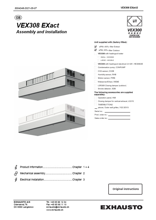
VEX308 EXactAssembly and installationProduct information........................................Chapter1 + 4Mechanical assembly.....................................Chapter2Electrical installation.......................................Chapter 3Unit supplied with (factory fitted):ePM 10 60%--filter Extract ePM 1 55%--filter Outdoor VEX308 with heatingcoil waterSMALL - HW308SELARGE - HW308LEVEX308 with heatingcoil electrical 2,4 kW - HE30802E Condensation pump, CONPUMP CO2-sensor, CO2B Humidity sensor, RHB Motion sensor, PIRB Webserver/EXact, WEBE LSR308 Closing damper (outdoor) Smoke detector, SDBThe following accessories are supplied separately:Operation panel, HMIClosing damper for vertical exhaust, LS315 TIMERBUTTON2pieces, Outer wall grilles, YGC Ø315Serial no.: Prod. order no.: Sales order no.:Original instructions3004248-2021-05-07VEX308 EXact2EXHAUSTO A/S Odensevej 76DK-5550 LangeskovTel. +45 65 66 12 34Fax +45 65 66 11 10********************www.exhausto.dk1.Product information1.1.Location in room....................................................................................................51.1.1.Optimum location ............................................................................................51.1.2.Space requirements ........................................................................................51.2.Application.............................................................................................................61.3.Designations used in these instructions.............................................................61.3.1.Simplified diagram............................................................................................61.4.Description.............................................................................................................81.4.1. Construction of the VEX unit...........................................................................81.4.2.VEX unit, parts and materials...........................................................................91.5.Principal dimensions. (10)Ceiling mounting - visible ..............................................................................101.5.1.Partly integrated ceiling mounting (11)2.Mounting2.1.Unpacking.............................................................................................................122.2.Wall mounting (accessories for some models).................................................122.2.1.Requirements for wall ...................................................................................122.2.2.Instructions and warnings .. (12)Wall mounting step by step (12)2.3.Ceiling mounting..................................................................................................132.3.1.Ceiling requirements......................................................................................132.3.2.Instructions and warnings .............................................................................132.3.3.Ceiling mounting step by step .......................................................................142.4.Partly integrated mounting.................................................................................142.5.Connection of condensation outlet....................................................................152.5.1.Condensation outlet guide channels (if condensation pump is mounted)......152.6.Connection of water heating coil (option).........................................................152.6.1.Connecting the water. (15)3.Electrical installation3.1.Supply voltage and fuses....................................................................................163.1.1.Position of power socket.. (16)Maximum power consumption ......................................................................163.1.2.Permanent installation (16)4.Technical data4.1.Weight, corrosion class, temperature ranges, etc............................................174.2.Electrical data for unit without heating coil......................................................174.3.Data for unit with heating coil.............................................................................174.3.1.Electric heating coil........................................................................................174.3.2.Water heating coils.........................................................................................184.3.3.MVM motor valve ..........................................................................................194.4.Condensate pact filters.....................................................................................................194.6.Capacity diagram and diagram for specific power consumption...................204.6.1.Capacity diagram...........................................................................................204.6.2.Capacity diagram - mounting on "duct system" ............................................214.6.3.Specific power consumption, SFP . (22)2/24Symbols, terms and warningsProhibition symbolFailure to observe instructions marked with a prohibition symbol may result in serious or fatal injury.Danger symbolFailure to observe instructions marked with a danger symbol may result in personal injury and/or damage to the unit.ScopeThis instruction manual is for use with EXHAUSTO VEX-type air handling units.Please refer to the product instructions regarding accessories and extra equip-ment.The instructions must be fully observed to ensure personal safety and to protect the equipment and ensure its correct operation. EXHAUSTO A/S accepts no liabil-ity for accidents caused by equipment not used in accordance with the manual’s instructions and recommendations.Prohibited usesThe VEX unit is not to be used to transport solid particles or in areas where there is a risk of explosive gases.Warnings:StartupThe unit must not be started up until it is fully mounted with door and duct connections.Opening the unitDo not open the service door until the supply voltage has been disconnected (remove plug from socket) and the fans have stop-ped.Duct termination atwallMount a permanent protective mesh to the exhaust and outdoor air connection, using a mesh size of max. 20 mm. For example,use the EXHAUSTO outer wall grilles.Information plateThe VEX unit information plate shows:●VEX model (1)●Production order no. (2)12NB:Always have the production number ready when contacting EXHAUSTO A/S.3/24NB:Find the newest version of the publication by searching for the order number on the EXHAUSTO website under DownloadsSupply air/extract air This instruction manual uses the following terminology:●Supply air (air blown in)●Extract air (air removed)●Outdoor air●Exhaust airFront page - Acces-sories The front page of the instruction manual contains a checklist, detailing the acces-sories delivered with the VEX unit.4/241. Product information1.1 Location in room1.1.1 Optimum locationAs far as possible the unit should be located in the middle of the wall.Avoid placing the VEX308 on the long side of narrow rooms.1.1.2 Space requirements0The sketch shows how much space is required under the unit for opening the door and servicing. The dimensions at the sides of the unit indicate the minimum clear-ance for optimum servicing conditions.R D 13146-015/241.2 ApplicationComfort ventilation EXHAUSTO's VEX308 unit is used for comfort ventilation in frost-free single-room locations. The VEX unit is designed for wall or ceiling mounting and must be usedas such.Operating temperature range for unit see section "Technical data".1.3 Designations used in these instructions1.3.1 Simplified diagramWith integral waterheating coil, HCW(top view)6/24With integral elec-tric heating coil,HCE (top view)7/241.4 Description1.4.1 Construction of the VEX unitThe drawing below shows an overview of the VEX unit construction. Details of HCW and HCE are viewed from below:EC H WC HR D 13198-038/241.4.2 VEX unit, parts and materialsCabinet The exterior of the cabinet is made of Aluzinc® and the cabinet is insulated with20 mm sound insulation material.Fans The unit contains two centrifugal fans with EC motors for extract air and supply air.Counter flow heat exchanger The unit's counterflow heat exchangers are made of aluminium and are highly effi-cient. The counterflow heat exchangers can be taken out and cleaned.Filters The unit includes integral compact filters on both extract air and supply air sides, the ePM10 60% and ePM1 55% filter respectively.Condensation out-let The condensation tray is located under the counterflow heat exchangers. There will only be a condensation outlet from the condensation tray if a condensation pump has been purchased. See also section on connection of condensation out-let.Bypass damper The unit has a variably adjustable bypass damper for temperature regulation and de-icing of counterflow heat exchangers during operation. See operating and serv-ice instructions for further description of de-icing.9/241.5 Principal dimensionsCeiling mounting - visibleR D 13126-02AA10/241.5.1 Partly integrated ceiling mountingR D 13446-03A-A3004248-2021-05-07Product information2. Mounting2.1 UnpackingStandard delivery●VEX308 unit●Housing panels packed separately●Wall brackets premounted on VEX (accessories on some models)●Ceiling brackets, supplied separatelySee information about included accessories on front page of these instructions. Any included ac-cessories2.2 Wall mounting (accessories for some models)2.2.1 Requirements for wallFor wall mounting, it is a requirement that the wall is:●flat●vibration-resistant●plumb (max. 4 mm per metre)●in a material suitable for safe mounting of the unit2.2.2 Instructions and warningsDimensioning Wall mountings must be dimensioned from the unit's weight.Mounting must be carried out in accordance with the ProjectManager's instructions.For wall mounting the two front ceiling brackets should also beused.Suspension The unit must be suspended with the door facing the floor. Theunit must not be mounted in any other way.The housing panels must be fixed with the accompanyingscrews.Wall mounting step by stepSee the attached installation guide (3004368).NB The dimensions of the wall template will match when held right up to the ceiling.2.3 Ceiling mounting2.3.1 Ceiling requirements0When fitting the unit to a ceiling, the ceiling must be:●flat●vibration-resistant ●horizontal●designed to bear the weight of the unit2.3.2 Instructions and warnings DimensioningCeiling mountings must be dimensioned from the unit's weight.Mounting must be carried out in accordance with the Project Manager's instructions.SuspensionThe unit must be suspended with the door facing the floor. The unit must not be mounted in any other way.The housing panels must be fixed with the accompanying screws.2.3.3 Ceiling mounting step by stepSee the attached installation guide (3004368).*) To be carried out in the event that the VEX has not been ordered with exhaust/outdoor air connection via the ceiling.2.4 Partly integrated mountingInstallationInstallation of the partly integrated VEX is carried out as described in sections 2.2.and 2.3.Access to control systemWhen carrying out installation, ensure there is access to the control system. EX-HAUSTO recommends that the part of the ceiling next to the control system can be removed.NBThe partly-integrated VEX extracts a small amount of air above the suspended ceiling, which can cause the filter to soil more quickly than usual. EXHAUSTO rec-ommends leaving a 10 mm gap between the cabinet and the suspended ceiling.2.5 Connection of condensation outlet2.5.1 Condensation outlet guide channels (if condensation pump is mounted)Wall-mounted VEX On wall-mounted units the condensation outlet is positioned with the outlet pass-ing through the exhaust duct.Ceiling-mounted VEXOn ceiling-mounted units the condensation outlet is led through the internal guidechannels (rubber sleeves) out of the unit to the drain.The penetrations in the unit must be executed so as to retain air tightness.Condensate pump (optional/accesso-ry)For technical data, see final section.2.6 Connection of water heating coil (option)2.6.1 Connecting the water Valves for water connectionIt is recommended that shut-off valves are mounted on both water connections toenable the flow to be interrupted for servicing.The dimensioning of valves, pipes, etc. and the connection of the water heating coil must always be carried out by authorised fit-ters in accordance with applicable regulations and legislation.Position of bleeder valve on VEX See keyed drawing for position of internal bleeder valve.Automatic bleeder valveIf the water connection is executed with vertical riser, so the heating coil in the VEX308 is the highest point in the pipe system, it is recommended that an auto-matic bleeder valve is fitted at the highest point on the supply and return pipes.3. Electrical installation3.1 Supply voltage and fuses3.1.1 Position of power socketThe supply cable is fitted with a 230V plug and can thus be connected to a powersocket.Fit the power socket for the supply voltage close to the VEX unit and preferably within the easy reach of users of the room.Maximum power consumptionFuses The installation must be protected with a max. 16A fuse.3.1.2 Permanent installationIf the plug is cut off and the cable mounted in a permanent installa-tion, an isolation switch must be established at the time of installa-tion.Permanent installation must be carried out by an authorised electri-cian.3004248-2021-05-07Electrical installation4. Technical data4.1 Weight, corrosion class, temperature ranges, etc.WeightDoor25.5 kgCounter flow heat exchanger 2 x 11 kgMotor section 2 x 6.0 kgTotal weight184.5 kg incl. HW308SEPartly integrated203.0 kg incl. HW308SE Corrosion class,cabinet Corrosion class Corrosion class C4 in accordance with EN ISO 12944-2Temperature rangesOutdoor air temperature-40 - +40°CAmbient temperature (operating)-30 - +40ºCAmbient temperature when not in operation (storage, transport)-40 - +60ºCThe temperature ranges given are dependent on the type of installation, humidity,airflow, the balance between airflows, ducts and insulation and room temperature.If using pre-heating coils, the ambient temperature can be reduced.At temperatures below -25˚C, use of a thermostatically controlled heater in auto-mated control box is recommended.4.2 Electrical data for unit without heating coilVoltage 1 x 230 V+N+PEMaximum output575 WMaximum power consumption 2.5 A4.3 Data for unit with heating coil4.3.1 Electric heating coilElectrical data forVEX with electric heating coilHE30802E Voltage 1 x 230 V+N+PE Maximum output, HE30802E2975 W Maximum power consumption12.9 AData, thermal cut-out Thermal fuse, TSA7070 ℃Thermal fuse, TSA9090 ℃Contact type NC (Normally closed)Maximum load 1.6 A @ 24 V DC NB Motors and heating coils may not be interrupted/switched off via OH70 and OH904.3.2 Water heating coilsElectrical data forVEX with water heating coil HCW Voltage 1 x 230 V+N+PE Maximum output575 W Maximum power consumption 2.5 AWater heating coildataOutput, K VS mv.Conditional upon: Supply temperature of water t F= 50°C and ΔT = 20K.4.3.3 MVM motor valve4.4 Condensate pumpCondensate pumpMaximum power consumption16WMaximum lifting height 5.0mHose dimension dia. 4/8 mm 4.5 Compact filtersFilter data, VEX308,filter data accordingto ISO168904.6 Capacity diagram and diagram for specific power consumption4.6.1 Capacity diagram Read control volt-ageWhen an EXact control panel (HMI) is connected to the VEX unit, the control volt-age can be read from menu 2.3 and thereby give a reasonable reading of airflow on the diagram. Conditional upon: 750 m 3/h at 35 Pa.1) Visible unit max. 750 m 3/h2) Partly integrated unit max. 650 m 3/h4.6.2 Capacity diagram - mounting on "duct system"1) Visible unit max. 750 m3/h2) Partly integrated unit max. 650 m3/h21/244.6.3 Specific power consumption, SFP1) Visible unit max. 750 m3/h2) Partly integrated unit max. 650 m3/h22/243004248-2021-05-0723/24。
GA308

筒烘 房 、 前后浆槽 的上浆 辊 和引 纱 辊 分 别 出 7只 电
该浆纱 机采 用 了大卷装 调 幅车 头 , 功能 齐全 , 整
采用 自稳零 的 I L 60运 放, 密 电压基 准使用 C 75 精 MC 43 使得在 ~1 ~4 10 , 0 5℃环境温度下 的零漂 < 0 05℃ , 不 影 响 控 温 精 度 WKY一20 0 而 0 F采
=
大, 以使 K n值增大 , 而使 ( ) 出的温控 阀 从 8 式计算 开启 的 占空 比减小 。当欠 调 大 于 06℃ 时 . 计算 在
维普资讯
・
纺 织 电气 ・ 步提高, 测温 元件 采用 P l0铂 热 电 阻 , 温 电桥 的其 它 电 t0 测 阻 和放大 环节 的电阻 , 采用康铜 丝线 绕 电阻 , 放 均 运
效地 消除这 个偏 差 。 为了使 温 控精 度 进
采用一 个 逻辑 判 断方 法 来 修 正 K 值 。当 超 凋 大 于 06℃时 . 在公 式 (2 的 括 号前 面加 一 个 比例 系数 1) K . 计算 新 K值 时 , 计 算 Kn的 比例 系数 K !在 使 增
控 瀑差 为 十0 8℃ , 一0 5℃
参 考 文 献
这种 白适 应 温控 方法在 邵 阳第 二 纺织机械 厂 的 E P8 B C 6型和 WKY一20 0 F型 二种 染色 机 电脑 温控 仪 上采 用 , 并在邵 阳第 二纺 织 机 械 厂生 产 的小浴 比 染 色机上 运用 , 获得 了满意 的温控 效果 。 在实 际应用 中 , 由于( ) 的 B×Y( —L—1 8式 n ) 数值很 小 , 故我们 分 二 种产 品应 用这 种 自适 应 温控 方法 。一种 是 E P=6型 温控 仪 不 带 ( ) 的 B× B( 8 8式
超同步GA手册(完整资料).doc

【最新整理,下载后即可编辑】第一章序言感谢您购买北京超同步科技有限公司生产的BKS伺服控制器。
BKS伺服控制器是北京超同步科技有限公司研制、开发生产的高质量、多功能、低噪音的交流伺服控制器。
BKS伺服控制器是鼠笼式电机(IM)的伺服控制器,可对普通鼠笼式电机和变频电机的位置、转速、加速度和输出转矩通过编程方式进行控制,BKS伺服控制器的研制成功为传动控制领域带来了生机。
BKS伺服控制器核心采用32位CPU对电机全数字控制。
电机能够以极低的速度运行(1rpm甚至1/8rpm)。
具有RS232和RS422两种通讯接口,22KW以下内置制动单元。
具有按标准配置、用于定位的码盘接口和用于速度、位置跟随的第二码盘;用于顺序控制的12点输入、8点输出接口及模拟量输入输出接口等。
因此能实现对鼠笼式电机进行高性能的控制。
不仅能够满足普通变频器所能达到的技术指标,而且能够应用在例如数控铣床的进给轴这种要求定位精度非常高的领域。
在数控机床、电动汽车等领域应用前景十分广泛。
在使用BKS伺服控制器之前,请您仔细阅读该手册,以保证正确使用。
错误使用可能造成控制器运行不正常、发生故障或降低使用寿命,甚至发生人身伤害事故。
因此使用前应反复阅读本说明书,严格按说明使用。
本手册为随机发送的附件,务必请您使用后妥善保管,以备今后对控制器进行检修和维护时使用。
1.1开箱检查注意事项在开箱时,请认真确认:在运输中是否有破损现象;控制器铭牌的型号、规格是否与您的订货要求一致。
如发现有遗漏或不相符的情况,请速与供货商联系解决。
1.2 控制器的铭牌在控制器箱体的右下方,贴有标示控制器型号及额定值的铭牌,铭牌内容如图1-1所示1.3 控制器型号说明1.4 安全注意事项“危险”与“注意”的定义:危险! 如果没有按要求操作,可能造成严重设备损坏或人员伤害注意! 如果没有按要求操作,可能造成中等程度的人员伤害或轻伤,或造成物质损失图1-1 控制器的铭牌1.4.1 安装1.4.2 配线1.4.3 维护1.5 使用的注意事项1.5.1 关于电动机及机械负载1、与工频运行比较北科伺服控制器为电压型控制器,输出电压是PWM波,含有一定的谐波。
GA308型多单元浆纱机的研发

GA308型多单元浆纱机的研发浆纱在织造过程中是一个非常重要的工序,它是提高布机织造质量和效率的关键工序。
郑州纺织机械厂通过长期对国内外纺织市场的调查,吸取国内外最新型浆纱机的特点,应用高新技术研发的GA 308型多单元浆纱机属高档浆纱机,其各项指标均达到了2000年的国际先进水平。
一、主要结构及技术特征该浆纱机主要由双层经轴架、双浸四压高压浆槽、分层及合并烘干的高架烘房、大卷装调幅车头及计算机集中控制的电控部分组成。
其中织轴卷绕、拖引辊、烘房部分、前后浆槽的上浆辊和引纱辊分别由7只电机拖动,故该机称为7单元拖动的GA 308型浆纱机。
1.经轴架采用组合式双层经轴架,每4只经轴为1组。
经轴退绕张力采用恒张力自控装置,每只浆槽的最大退绕张力为3 kN。
在经纱退绕过程中,该装置的经轴摩擦盘的摩擦阻力随着退绕直径的减小而减小,从而使退绕张力基本恒定,同时也能够保证两个浆槽及各个经轴的退绕张力一致。
2.浆槽采用双浸四压的高压上浆系统。
两只浸没辊均有侧压功能,浸压次数增加,压浆力加大,从而提高了浆液的渗透性和上浆工艺适应性。
第二压浆辊采用中固辊结构,最大压力可达40 kN。
应用计算机模拟设计,在设计压力范围内压浆辊和上浆辊的变形量一致,保证经纱上浆的横向均匀性。
主浆槽和预热浆槽联为一体,为箱式夹层结构,均采用不锈钢制造。
浆液循环方向与经纱方向相反,可提高上浆质量。
浆液供给采用自动控制,溢流形式为瀑布式,从而保证浆槽表面浆液流动性好,无浆斑,各点温度一致。
经纱进入浆槽前区有一套引纱装置,从而可控制经纱的喂入张力,利于经纱上浆的渗透。
3.烘房全机采用12只直径800 mm的烘筒进行烘燥,总烘燥量为800 kg/h,其中8只预烘烘筒表面喷涂聚四氟乙烯。
每只浆槽分二层烘燥,降低烘燥覆盖系数,保持浆纱的浆膜完整,毛羽减少。
然后进入4只合并烘筒进行烘燥,根据品种调节温度,达到所需的回潮率。
每只浆槽和烘房之间配置一根湿分绞装置,在分绞棒内通入冷水,由于棒内与棒外的温差产生表面冷凝水,不易挂浆,利于分绞。
建伍308对讲机调整[技巧]
![建伍308对讲机调整[技巧]](https://img.taocdn.com/s3/m/2e5782a568dc5022aaea998fcc22bcd126ff4293.png)
建伍308对讲机调整308对讲机调整一、频率范围:;TK208:150MHZ;TK308:450MHZ 二、本机程序主要采用三大模式:频率设定模式;维修模式;用户模式。
1.频率设定模式:在这个模式中,可设定各信道的频率,还可以设定各种功能和工作参数,打开电源,虽然可以看到显示频率,但是不能接收和发射。
如:***?** 2.维修模式:在这个模式中,显示屏显示频率数值,可以进行接收和发射。
如:一***?** 3.用户模式:这个模式是用户通常使用的模式,打开电源显示屏显示存储信道号码,在这个模式中可以使用的功能是在频率设定模式中所设定的。
如:CH*三、本机出厂状态:打开电源,便进入频率设定模式,必须在此模式下设定信道和功能后,才可以进入用户模式使用。
四、设定信道: 1.选定频率:开机进入频率模式,首先对频率进行选择。
按一下MONI键,有光标"一"闪烁,旋编码开关,频率以"MHZ"为单位增减,再接一次MONI键光标消失,旋编码开关,频率以" KHZ"为单位增减,选定所需要的频率。
2.频率写入信道:按一次"CSET"键,出现**闪烁,旋编码开关,选择所需要的信道(信道范围00-39,再按一次"CSET"键,闪烁消失,这时接收频率已写入所选择的信道;按方法1选定发射频率,按一次"CSET"键,出现"*闪烁,按住PTT再按CSET键,闪烁消失,这时发射频率已写入所选择的信道。
(注:如某一信道接收频率未写或未写进,发射频率就不能写入。
)3.确认频率写入:在频率模式下,按REV键,显示±***。
** **显示内容为接收频率及信道号码,再按"CEST"键,显示R±***。
** **显示内容为发射频率及信道号码以上两次确认说明信道的接收和发射都已设定,如设定两个或两个以上信道,旋编码开关,所写入频率及信道将显示出来。
优利德 MSO UPO3000CS系列使用手册 说明书

MSO/UPO3000CS系列示波器使用手册REV32023.11尊敬的用户:您好!感谢您选购全新的优利德仪器,为了正确使用本仪器,请您在本仪器使用之前仔细阅读本说明书全文,特别有关“安全注意事项”的部分。
如果您已经阅读完本说明书全文,建议您将此说明书进行妥善的保管,与仪器一同放置或者放在您随时可以查阅的地方,以便在将来的使用过程中进行查阅。
优利德科技(中国)股份有限公司版权所有。
如果原购买者自购买该产品之日起一年内,将该产品出售或转让给第三方,则保修期应为自原购买者从UNI-T或授权的UNI-T分销商购买该产品之日起一年内。
探头及其他附件和保险丝等不受此保证的保护。
如果在适用的保修期内证明产品有缺陷,UNI-T可自行决定是修复有缺陷的产品且不收部件和人工费用,或用同等产品(由UNI-T决定)更换有缺陷的产品。
UNI-T作保修用途的部件、模块和更换产品可能是全新的,或者经修理具有相当于新产品的性能。
所有更换的部件、模块和产品将成为UNI-T的财产。
以下提到的“客户”是指据声明本保证所规定权利的个人或实体。
为获得本保证承诺的服务,“客户”必须在适用的保修期内向UNI-T通报缺陷,并为服务的履行做适当安排。
客户应负责将有缺陷的产品装箱并运送到UNI-T指定的维修中心,同时预付运费并提供原购买者的购买证明副本。
如果产品要运送到UNI-T 维修中心所在国范围内的地点,UNI-T应支付向客户送返产品的费用。
如果产品送返到任何其他地点,客户应负责支付所有的运费、关税、税金及任何其他费用。
本保证不适用于由于意外、机器部件的正常磨损、在产品规定的范围之外使用或使用不当或者维护保养不当或不足而造成的任何缺陷、故障或损坏。
UNI-T根据本保证的规定无义务提供以下服务:a)修理由非UNI-T服务代表人员对产品进行安装、修理或维护所导致的损坏;b)修理由于使用不当或与不兼容的设备连接造成的损坏;c)修理由于使用不符合本说明书要求的电源而造成的任何损坏或故障;d)维修已改动或者与其他产品集成的产品(如果这种改动或集成会增加产品维修的时间或难度)。
GA308—2001《安全防范系统验收规则》

(GA/308—2001)《安全防范系统验收规则》2001—08—23中华人民共和国公安部发布2001—12—01实施前言本标准的全部技术内容为强制性。
本标准是GA/T 75-1994 《安全防范工程程序与要求》的配套标准,对安全防范系统的验收提出了必须遵循的规则。
本标准没有相同的国际或国外先进标准可供采用,在具体内容上主要参考了有关电子系统、计算机信息系统安装、验收的技术规范、设计要求和安全技术防范产品标准,并结合国内安全防范系统设计和安装的实践经验编写而成。
ﻫ本标准由中华人民共和国公安部科技局提出。
ﻫ本标准由全国安全防范报警系统标准化技术委员会归口。
本标准由上海市公安局技术防范办公室、公安部第三研究所、公安部安全防范报警系统产品质量监督检验测试中心、上海三盾安全防范系统公司、公安部安全与警用电子产品质量检测中心联合起草。
ﻫ本标准主要起草人:孙金元、李祥发、汪广杰、郑文、沈伟斌、陶焱升、李仲男。
1范围本标准对安全防范系统的质量验收,从设计、施工、效果及技术服务等方面提出了必须遵循的基本要求,是对安全防范系统(工程)进行验收的依据。
本标准适用于一、二级安全防范系统(工程)的验收,三级安全防范系统(工程)的验收可适当简化。
2引用标准下列标准所包含的条文,通过在本标准中引用而构成为本标准的条文。
本标准出版时,所示版本均为有效。
所有标准都会被修订,使用本标准的各方应探讨使用下列标准的条文。
本标准出版时,所示版本均为有效。
所有标准都会被修订,使用本标准的各方应探讨使用下列标准最新版本的可能性。
GB/T16571-1996文物系统博物馆安全防范系统设计规范GB/T16676-1996银行营业场所安全防范系统设计规范(以被GA/38—2004替代)GB/50057-1994建筑防雷设计规范GB/50198-1994民用闭路监视电视系统工程技术规范GA/T74-2000安全防范系统通用图形符号GA/T75-1994安全防范工程程序与要求JGJ/T16-1992建筑电气设计技术规程3 定义本标准采用下列定义。
安全防范系统验收规范GA308

安全防范系统验收规范GA 3081 范围本标准对安全防范系统的质量验收,从设计、施工、效果及技术服务等方面提出了必须遵循的基本要求,是对安全防范系统(工程)进行验收的依据。
本标准适用于一、二级安全防范系统(工程)的验收,三级安全防范系统(工程)的验收可适当简化。
2 引用标准下列标准所包含的条文,通过在本标准中引用而构成为本标准的条文。
本标准出版时,所示版本均为有效。
所有标准都会被修订,使用本标准的各方应探讨使用下列标准最新版本的可能性。
GB/T16571—1996 文物系统博物馆安全防范系统设计规范GB/T16676—1996 银行营业场所安全防范系统设计规范GB50057—1994 建筑防雷设计规范GB50198—1994 民用闭路监视电视系统工程技术规范GA/T74—2000 安全防范系统通用图形符号GA/T75—1994 安全防范工程程序与要求JGJ/T16—1992 建筑电气设计技术规程中华人民共和国公安部2001-08-23 2001 -12-01实施GA 308—20013 定义本标准采用下列定义。
3.1 安全技术防范(简称技防)以运用技防产品、实施技防工程为手段,结合各种相关现代科学技术,预防、制止违法犯罪和重大治安事故,维护社会公共安全活动。
3.2 安全技术防范产品(简称技防产品)用于防入侵、防盗窃、防抢劫、防破坏、防爆炸和安全检查等方面的特种器材。
3.3 安全防范系统(工程)以维护社会公共安全和预防、制止重大治安事故为目的,综合运用技防产品和其他相关产所组成的电子系统或网络。
4 验收条件4.1 初步设计方案通过论证根据GA/T75—1994规定,一、二级系统(工程)必须经初步设计方案论证通过,并根据论证意见由建设单位和设计、施工单位共同签署整改落实意见。
4.2 系统试运行达到设计要求并为建设单位认可4.2.1试运行:系统调试开通后,应至少试运行一个月,并做好试运行记录(见表1)。
Gigabit Ethernet Switch GS308 安装指南说明书

Guide d'installationCommutateur Ethernet Gigabit GS308Temps d'installation estimé : 5-10 minutesContenu de la boîteCette boîte contient :•Commutateur Ethernet Gigabit GS308•Adaptateur secteur CA•Guide d’installation (ce document)Préparation pour installer le commutateurPlacez le commutateur sur une surface horizontale et plane, tellequ'une table, un bureau ou une étagère. Vous pouvez utiliser desvis pour fixation murale (non fournies) si vous souhaitez accrocherle commutateur au mur.Assurez-vous que l'endroit choisi est :•N'est pas directement exposé au soleil et ne se trouve pas àproximité d'un système de chauffage.•Pas encombré ni bondé. Il doit y avoir au moins 2 pouces(5cm) d'espace d'air sur tous les côtés du commutateur.•Bien ventilé (particulièrement s'il est dans un placard).Chaque périphérique devra être connecté au commutateur aumoyen d'un câble Ethernet de catégorie 3 (10 Mbit/s) ou catégorie 5(100 Mbit/s) ou catégorie 5e (1000 Mbit/s) doté de connecteursRJ-45. Chaque câble Ethernet doit mesurer moins de 328 pieds(100 mètres).Installez le commutateur et connectez lespériphériques1.Placez le commutateur sur une surface plane ou fixez-le àl'aide des vis.2.Pour chaque périphérique, insérez une extrémité d'un câbleEthernet dans un port du commutateur et branchez l'autreextrémité dans le port réseau du périphérique.3.Branchez le cordon de l'adaptateur secteur à l'arrière ducommutateur, puis branchez l'adaptateur à une sourced'alimentation (telle qu'une prise ou une rallonge électrique).4.Examinez les voyants :••Pour chaque prise RJ-45 connectée à un périphériquealimenté, vérifiez que le voyant de connexion est allumé etqu'il clignote lorsqu'il est en activité.Remarque :Si un voyant ne fonctionne pas comme indiqué allez àla section Dépannage.Modemà 8 ports GS308Août 2012Ce symbole a été apposé conformément à la directive européenne 2002/96 sur la mise au rebut des équipements électriques et électroniques(directive WEEE - Waste Electrical and Electronic Equipment). En cas demise au rebut de ce produit dans un Etat membre de l'Union européenne,il doit être traité et recyclé conformément à cette directive.NETGEAR, le logo NETGEAR et Connect with Innovation sont des marquescommerciales et/ou des marques déposées de NETGEAR, Inc. et/ou des filiales deNETGEAR aux Etats-Unis et/ou dans d'autres pays. Les informations sont sujettes àchangement sans préavis. Les autres marques et noms de produits sont des marquescommerciales ou des marques déposées de leurs détenteurs respectifs. © 2012NETGEAR, Inc. Tous droits réservés. Pour une utilisation en intérieur uniquementdans tous les pays de l'UE et la Suisse.DépannageLe voyant d'alimentation n'est pas allumé.•Assurez-vous que le cordon d'alimentation est correctementbranché.•Assurez-vous que l'adaptateur d'alimentation est branché à uneprise ou une rallonge sous tension.•Vérifiez que vous utilisez bien l'adaptateur NETGEAR fourniavec votre commutateur.Le voyant de port d'un périphérique est éteint ou reste constammentallumé.•Assurez-vous que les connecteurs du câble sont bien insérésdans le commutateur et le périphérique.•Assurez-vous que le périphérique connecté est allumé.•Si le câble Ethernet est connecté à une carte interface réseau(NIC) ou à un autre adaptateur Ethernet, vérifiez que la carte oul'adaptateur est correctement installé(e) et fonctionne.•Assurez-vous que le câble mesure moins de 328 pieds(100 mètres).Support techniqueNous vous remercions d'avoir choisi des produits NETGEAR. Aprèsl'installation de votre périphérique, notez le numéro de série inscritsur l'étiquette de votre produit. Il vous sera nécessaire pourenregistrer votre produit à : /register.L'enregistrement du produit est nécessaire pour utiliser le serviced'assistance téléphonique. Pour obtenir des mises à jour, de ladocumentation supplémentaire et de l'assistance des produits allezà : .Pour consulter la déclaration de conformité complète, rendez-voussur le site Web NETGEAR des déclarations de conformité pour l'UEà l'adresse :/app/answers/detail/a_id/11621.AVERTISSEMENT :n'empilez pas l'appareil et ne le placez pasdans des espaces réduits ou fermés, ou encore sur de la moquetteou un tapis. Assurez-vous de laisser un espace d'au moins 2 pouces(5 cm) autour de votre appareil.Caractéristiques techniquesCompatibilité des normes IEEE 802.3i 10BASE-T EthernetIEEE 802.3u 100BASE-TXIEEE 802.ab 1000BASE-TContrôle de flux IEEE 802.3xIEEE 802.1p et priorité TOS,File d'attente WRRIEEE 802.3azInterface réseau Connecteur RJ-45 pour 10BASE-T,100BASE-TX, ou 1000BASE-T Alimentation12Wmax.etentré*********** Consommation de courant(max)3,84WDimensions158 x 102 x 26 mm(6,22 po. x 4,02 po. x 1,02 po.) Poids465g (1,03 oz)Température defonctionnement0° à 40° C (32° à 104° F)Humidité de fonctionnement 90% d'humidité relative maximum, sans condensationHomologation d'agence de sécurité pour l'adaptateur d'alimentation Marque CE, CBPerformancesVitesse de filtrage detrame14 880 paquets/sec max. pour le port 10M148 800 paquets/sec max. pour le port 100M1 488 000 paquets/sec max. pour le port 1000MVitesse de transfertde trame14 880 paquets/sec max. pour le port 10M148 800 paquets/sec max. pour le port 100M1 488 000 paquets/sec max. pour le port 1000MTemps d'attente duréseau (pour despaquets de 64 bits)1000 Mbits/s : 3,193 µs100 Mbits/s : 10,167 µs10 Mbits/s : 82,819 µsTaille de la base dedonnées d'adresses4K MAC adressesFile d'attente dutampon192 Ko intégrés。
SYSP-308 多功能麥克風擴音器使用說明書说明书

1.將包裝內容的主機取出,用卡扣式腰帶扣住主機兩邊圓孔,通過腰帶 把主機繫在腰上或掛在肩上,可調整腰帶讓主機處於腰間適合的位置。
也可以不使用腰帶,直接使用主機後面的背夾於皮帶或褲邊上。
2.將頭戴式有線麥克風,調整好麥克風位置,最好離嘴前方1~2㎝處, 把頭戴式有線麥克風另一端插入主機上方MIC插口內。
注意:在小面積範圍使用時,請在連接麥克風前將擴音器音量調整至最小位 置,不要將麥克風靠近擴音器喇叭,須將麥克風和主機保持50㎝外的 空間距離,以免聲音過大或麥克風距離太近造成回音、嘯聲的現象。
使用方法操作方式長按電源鍵 " " 3秒以上,此時藍色指示燈亮,表示擴音器進入開 機工作狀態。
關機方式與開機相同,長按電源鍵 " " 3秒以上,藍 色指示燈熄滅,此時為關機狀態。
注意:若操作使用過程出現死機現象,可長按電源鍵 " "10秒以上復歸 解決,復歸後再重新開機播放器可正常工作。
注意:在音樂播放狀態下,按下" "鍵,暫停播放,將TF卡/USB先行拿 下,才可進行擴音功能,慢慢調整音量旋鈕至一半位置可以試講話, 多次調試至您滿意的聲音效果,如果調至最大聲音時產生嘯叫聲,可 把麥克風的距離拉開些,建議麥克風與嘴巴的距離為1~2㎝左右最佳。
開機後藍色指示燈亮,表示機器可正常使用,將頭戴式有線麥克風插入本 機MIC插口,系統則自動判定為擴音狀態。
在TF卡/USB音樂播放時,按" "鍵,可以進行單曲循環播放,藍 色指示燈快速閃爍;若要取消循環播放,再按" "鍵停止循環播 放,進行正常播放狀態,藍色指示燈正常閃爍。
在播放TF卡/USB中的音樂或教學音頻內容時,按下" "鍵即可,進行復 讀功能內容設定,藍色指示燈停止閃爍,當您需要的復讀的內容段完成好, 再按一次 " "鍵,藍色指示燈快速閃爍,此時表示處於復讀狀態;若 要取消復讀功能,再按一次" "鍵即可,進入TF卡/USB音樂播放狀態。
建武308说明书

建武308说明书(总8页) -CAL-FENGHAI.-(YICAI)-Company One1-CAL-本页仅作为文档封面,使用请直接删除建武308说明书一、3大状态模式及转换。
1、频率设定模式。
在这个模式中,可以设定各信道的频率,还可以设定各种功能和工作参数。
每当接通电源时,可以看到“LCD”屏显示有频率数,但不能进行接收和发射信号。
进入该模式的方法是:(1)在出厂状态下,接通电源,直接进入该模式。
(2)关闭电源,卸开机壳,把控制板右上角印有“CH OFF”标志的两个圆点暂时短接,然后,接通电源,能够从用户使用模式转换为该模式。
(3)关闭电源,按住“CTC ”和“PTT”键,同时接通电源,能够从维修模式转换为该模式。
2、维修模式。
在这个模式中,可以看到“LCD”屏显示有信道号码,频率数据,并且可以在屏显的信道频率上接收和发射信号。
其工作参数是在频率设定模式中设置的。
进入该模式的方法是:按信“CTC ”和“PTT”键,同时接通电源,能够从频率设定模式转换为该模式。
3、用户使用模式,这个模式是一般用户通常使用的模式。
在这个模式中,可以看到“LCD”屏显示有存储工作参数的信道号码,用户在该信道接收和发射信号,其显示的信道号码和存储的参数是在频率设定模式中设置的。
进入该模式的方法是:按住“REV”键,同时接通电源,能够从频率设定模式转换为该模式,但对讲机所有存储信道未设定频率数据即全空信道时,不能进入该模式。
二、各操作键在3大状态模式下功能作用。
如下图。
三、功能参数设置。
1、进入菜单模式。
在频率设定模式状态下,关闭电源,按住“SCAN”键,同时接通电源即可。
此时,“LCD”屏右上角显示功能序号“N001”,中央部分显示功能待定值。
2、改变功能序号,设置参数。
用“ENC/SQL”旋钮从“N001 ”开始改变功能序号,顺时针方向旋转,序号增大,反之减小。
用“LOW”键设置功能参数,每按一次,参数值就变化一次。
GA 308-2019安全防范系统验收规则共15页

安全防范系统验收规则中华人民共和国公共安全行业标准GA 308-200安全防范系统验收规则Acceptance check criterion of security and alarm systems2001—08—232001—12—01实施中华人民共和国公安部发布 GA 308-2001前言本标准的全部技术内容为强制性。
本标准是GA/T 75-1994 《安全防范工程程序与要求》的配套标准,对安全防范系统的验收提出了必须遵循的规则。
本标准没有相同的国际或国外先进标准可供采用,在具体内容上主要参考了有关电子系统、计算机信息系统安装、验收的技术规范、设计要求和安全技术防范产品标准,并结合国内安全防范系统设计和安装的实践经验编写而成。
本标准由中华人民共和国公安部科技局提出。
本标准由全国安全防范报警系统标准化技术委员会归口。
本标准由上海市公安局技术防范办公室、公安部第三研究所、公安部安全防范报警系统产品质量监督检验测试中心、上海三盾安全防范系统公司、公安部安全与警用电子产品质量检测中心联合起草。
本标准主要起草人:孙金元、李祥发、汪广杰、郑文、沈伟斌、陶焱升、李仲男。
中华人民共和国公共安全行业标准安全防范系统验收规则 GA 308-2001 Acceptance check criterion of security and alarm systems1范围本标准对安全防范系统的质量验收,从设计、施工、效果及技术服务等方面提出了必须遵循的基本要求,是对安全防范系统(工程)进行验收的依据。
本标准适用于一、二级安全防范系统(工程)的验收,三级安全防范系统(工程)的验收可适当简化。
2引用标准下列标准所包含的条文,通过在本标准中引用而构成为本标准的条文。
本标准的出版时,所示版本均为有效。
所有标准都会被修订,使用本标准的各方应探讨使用下列标准的条文。
本标准出版时,所示版本均为有效。
所有标准都会被修订,使用本标准的各方应探讨使用下列标准最新版本的可能性。
浆纱机实用手册

GA308/306A浆纱机实用手册郑州纺织机械股份有限公司2007. 05郑州纺织机械股份有限公司前言首先,衷心感谢国内外广大用户多年来对郑州纺织机械股份有限公司的支持和信任!GA308型多单元浆纱机自投放市场以来,目前已在市场开车已有300多台,对我国纺织技术进步做出了贡献。
该产品以其品种适用性广,可靠性高好,控制精度高,得到广大用户的认可,并产生了良好的经济效益和社会效益。
为了使用户厂更加熟练的掌握设备,充分发挥设备潜能,协助企业适应市场品种多、档次高、变化快的要求及对此技术的迫切需要,我公司根据近两年用户实际使用情况,总结经验,整理汇编了《GA308/306A浆纱机实用手册》,本手册注重生产实际,从浆纱机的相关配套设施开始,对机械、电气、工艺和操作几方面总结,以及设备的正确使用、维护及故障排查都作了详细的说明和举例。
本手册的汇编,也是对2005年出版的《GA308型浆纱机的原理及使用》的不断完善与改进。
郑州纺织机械股份公司始终坚持“以客户为中心”的用心服务,诚信为本,以满足客户的个性化需求为目标,回报用户,提升服务价值。
希望本手册能为浆纱机使用企业在实操中提供培训和指导。
鉴于时间关系,文中如有错误之处,敬请批评指正。
郑州纺织机械股份有限公司2007年5月内容索引第一章 GA308/306A浆纱机使用相关配套设施的基本要求 4-5 第二章安全常识 6-7 第三章GA308/306A浆纱机机械维护和保养及常见故障排查 8-16第四章 GA308/306A浆纱机电气维护和保养及常见故障排查 17-36第五章浆纱工艺交流及工艺实例分析 37-49 第六章GA308/306A浆纱机的操作要求50-53第一章浆纱机使用相关配套设施的基本要求1 每台GA308或GA306A前后道工序配套✧高速整经机配套1.5-2台,纱线纱支愈低配置量愈大。
✧配置高压调浆桶和低压供应桶各一只,容积0.8m3或配置低压调浆桶二只,供应桶一只,容积0.8m3。
《安全防范系统验收规则》GA 308-2001

精心整理《安全防范系统验收规则》GA308-20012001—08—23中华人民共和国公安部发布 2001—12—01实施 前言本标准的全部技术内容为强制性。
1 范围2 GB/TGB/T16676-1996 银行营业场所安全防范系统设计规范 GB 50057-1994 建筑防雷设计规范GB 50198-1994 民用闭路监视电视系统工程技术规范 GA/T74-2000 安全防范系统通用图形符号 GA/T75-1994 安全防范工程程序与要求 JGJ/T16-1992 建筑电气设计技术规程3定义本标准采用下列定义。
(1)安全技术防范(简称技防)以运用技防产品,实施技防工程为手段,结合各种相关现代科学技术,预防,制止违法犯罪和重大治安事故,维护社会公共安全的活动。
(2)安全技术防范产品(简称技防产品)用于防入侵,防盗窃,防抢劫,防破坏,防爆炸和安全检查等方面的特种器材。
(3)4验收条件4.14.24.2.14.2.2b)故障4.2.34.34.44.4.1部建成,经建设单位与设计,施工单位协商,对遗留问题有明确处理的办法,经试运行并为建设单位认可后,也可视为竣工。
4.4.2系统竣工后由设计,施工单位写出竣工报告。
竣工报告内容包括:工程概况,安装的主要设备,对照设计任务书或合同所完成的质量自我评估,提出维修服务条款。
4.5初验合格4.5.1由建设单位(含监理单位)组织设计,施工单位根据设计任务书或合同提出的设计使用要求进行初验,要求初验合作并写出初验报告。
参加初验的人员应签名。
4.5.2 初验包括以下内容:a 系统试运行评述;b 对照设计任务要求,系统功能检测情况及质量主观评论;c 对照正式设计方案,核对安装设备数量和型号的结果;d 施工质量初验意见(含隐蔽工程随工验收单,见表2)4.6系统检测4.6.1一,二级安全防范系统(工程)在正式验收前,设计,施工单位必须向公安技防管理部门申请办理委托系统检测手续,并由公安技防管理部门向检测机构出具检测委托书。
莫克斯 EDS-G308 系列 8G 端口全功能非管理网络开关说明书

EDS-G308Series8G-port full Gigabit unmanaged Ethernet switchesFeatures and Benefits•Fiber-optic options for extending distance and improving electrical noiseimmunity•Redundant dual 12/24/48VDC power inputs•Supports 9.6KB jumbo frames•Relay output warning for power failure and port break alarm•Broadcast storm protection•-40to 75°C wide operating temperature range (-T models)CertificationsIntroductionThe EDS-G308switches are equipped with 8Gigabit Ethernet ports and 2fiber-optic ports,making them ideal for applications that demand high bandwidth.The EDS-G308switches provide an economical solution for your industrial Gigabit Ethernet connections,and the built-in relay warning function alerts network managers when power failures or port breaks occur.The 4-pin DIP switches can be used for controlling broadcast protection,jumbo frames,and IEEE 802.3az energy saving.In addition,100/1000SFP speed switching is ideal for easy on-site configuration for any industrial automation application.A standard-temperature model,which has an operating temperature range of -10to 60°C,and a wide-temperature range model,which has an operating temperature range of -40to 75°C,are available.Both models undergo a 100%burn-in test to ensure that they fulfill the special needs of industrial automation control applications.The switches can be installed easily on a DIN rail or in distribution boxes.SpecificationsInput/Output InterfaceAlarm Contact Channels 1relay output with current carrying capacity of 1A @24VDC Ethernet Interface10/100/1000BaseT(X)Ports (RJ45connector)EDS-G308/G308-T:8EDS-G308-2SFP/G308-2SFP-T:6All models support:Auto negotiation speedFull/Half duplex modeAuto MDI/MDI-X connectionCombo Ports (10/100/1000BaseT(X)or 100/1000BaseSFP+)EDS-G308-2SFP:2EDS-G308-2SFP-T:2Standards IEEE 802.3for 10BaseTIEEE 802.3ab for 1000BaseT(X)IEEE 802.3u for 100BaseT(X)and 100BaseFXIEEE 802.3x for flow controlIEEE 802.3z for 1000BaseXIEEE 802.3az for Energy-Efficient EthernetDIP Switch ConfigurationEthernet Interface Broadcast storm protection,Jumbo Frame,IEEE 802.3az energy saving,100/1000SFPspeed switching,Port break alarmSwitch PropertiesJumbo Frame Size9.6KBMAC Table Size8KPacket Buffer Size4MbitsProcessing Type Store and ForwardPower ParametersConnection1removable6-contact terminal block(s)Input Voltage12/24/48VDC,Redundant dual inputsOperating Voltage9.6to60VDCReverse Polarity Protection SupportedInput Current EDS-G308:0.29A@24VDCEDS-G308-2SFP:0.31A@24VDCPhysical CharacteristicsHousing MetalIP Rating IP30Dimensions52.85x135x105mm(2.08x5.31x4.13in) Weight880g(1.94lb)Installation DIN-rail mounting,Wall mounting(with optional kit) Environmental LimitsOperating Temperature Standard Models:-10to60°C(14to140°F)Wide Temp.Models:-40to75°C(-40to167°F) Storage Temperature(package included)-40to85°C(-40to185°F)Ambient Relative Humidity5to95%(non-condensing)Standards and CertificationsEMC EN55032/35EMI CISPR32,FCC Part15B Class AEMS IEC61000-4-2ESD:Contact:6kV;Air:8kVIEC61000-4-3RS:80MHz to800MHz:10V/mIEC61000-4-3RS:800MHz to1GHz:20V/mIEC61000-4-4EFT:Power:2kV;Signal:2kVIEC61000-4-5Surge:Power:2kV;Signal:2kVIEC61000-4-6CS:10VIEC61000-4-8PFMF:100A/mHazardous Locations ATEX,Class I Division2Railway EN50121-4Safety UL508,EN62368-1Shock IEC60068-2-27Freefall IEC60068-2-32Vibration IEC60068-2-6Maritime DNV,LR,ABS,NKMTBFTime2,260,195hrsStandards Telcordia(Bellcore),GBWarrantyWarranty Period5yearsDetails See /warrantyPackage ContentsDevice1x EDS-G308Series switchInstallation Kit4x cap,plastic,for RJ45port2x cap,plastic,for SFP slot(-2SFP models)Documentation1x quick installation guide1x warranty cardNote SFP modules need to be purchased separately for use with this product. DimensionsOrdering InformationEDS-G3088–-10to60°CEDS-G308-T8–-40to75°CEDS-G308-2SFP62-10to60°CEDS-G308-2SFP-T62-40to75°C Accessories(sold separately)SFP ModulesSFP-1FELLC-T SFP module with1100Base single-mode with LC connector for80km transmission,-40to85°Coperating temperatureSFP-1FEMLC-T SFP module with1100Base multi-mode,LC connector for2/4km transmission,-40to85°C operatingtemperatureSFP-1FESLC-T SFP module with1100Base single-mode with LC connector for40km transmission,-40to85°Coperating temperatureSFP-1G10ALC WDM-type(BiDi)SFP module with11000BaseSFP port with LC connector for10km transmission;TX1310nm,RX1550nm,0to60°C operating temperatureSFP-1G10ALC-T WDM-type(BiDi)SFP module with11000BaseSFP port with LC connector for10km transmission;TX1310nm,RX1550nm,-40to85°C operating temperatureSFP-1G10BLC WDM-type(BiDi)SFP module with11000BaseSFP port with LC connector for10km transmission;TX1550nm,RX1310nm,0to60°C operating temperatureSFP-1G10BLC-T WDM-type(BiDi)SFP module with11000BaseSFP port with LC connector for10km transmission;TX1550nm,RX1310nm,-40to85°C operating temperatureSFP-1G20ALC WDM-type(BiDi)SFP module with11000BaseSFP port with LC connector for20km transmission;TX1310nm,RX1550nm,0to60°C operating temperatureSFP-1G20ALC-T WDM-type(BiDi)SFP module with11000BaseSFP port with LC connector for20km transmission;TX1310nm,RX1550nm,-40to85°C operating temperatureSFP-1G20BLC WDM-type(BiDi)SFP module with11000BaseSFP port with LC connector for20km transmission;TX1550nm,RX1310nm,0to60°C operating temperatureSFP-1G20BLC-T WDM-type(BiDi)SFP module with11000BaseSFP port with LC connector for20km transmission;TX1550nm,RX1310nm,-40to85°C operating temperatureSFP-1G40ALC WDM-type(BiDi)SFP module with11000BaseSFP port with LC connector for40km transmission;TX1310nm,RX1550nm,0to60°C operating temperatureSFP-1G40ALC-T WDM-type(BiDi)SFP module with11000BaseSFP port with LC connector for40km transmission;TX1310nm,RX1550nm,-40to85°C operating temperatureSFP-1G40BLC WDM-type(BiDi)SFP module with11000BaseSFP port with LC connector for40km transmission;TX1550nm,RX1310nm,0to60°C operating temperatureSFP-1G40BLC-T WDM-type(BiDi)SFP module with11000BaseSFP port with LC connector for40km transmission;TX1550nm,RX1310nm,-40to85°C operating temperatureSFP-1GEZXLC SFP module with11000BaseEZX port with LC connector for110km transmission,0to60°C operatingtemperatureSFP-1GEZXLC-120SFP module with11000BaseEZX port with LC connector for120km transmission,0to60°C operatingtemperatureSFP-1GLHLC SFP module with11000BaseLH port with LC connector for30km transmission,0to60°C operatingtemperatureSFP-1GLHLC-T SFP module with11000BaseLH port with LC connector for30km transmission,-40to85°C operatingtemperatureSFP-1GLHXLC SFP module with11000BaseLHX port with LC connector for40km transmission,0to60°C operatingtemperatureSFP-1GLHXLC-T SFP module with11000BaseLHX port with LC connector for40km transmission,-40to85°Coperating temperatureSFP-1GLSXLC SFP module with11000BaseLSX port with LC connector for1km/2km transmission,0to60°Coperating temperatureSFP-1GLSXLC-T SFP module with11000BaseLSX port with LC connector for1km/2km transmission,-40to85°Coperating temperatureSFP-1GLXLC SFP module with11000BaseLX port with LC connector for10km transmission,0to60°C operatingtemperatureSFP-1GLXLC-T SFP module with11000BaseLX port with LC connector for10km transmission,-40to85°C operatingtemperatureSFP-1GSXLC SFP module with11000BaseSX port with LC connector for300m/550m transmission,0to60°Coperating temperatureSFP-1GSXLC-T SFP module with11000BaseSX port with LC connector for300m/550m transmission,-40to85°Coperating temperatureSFP-1GZXLC SFP module with11000BaseZX port with LC connector for80km transmission,0to60°C operatingtemperatureSFP-1GZXLC-T SFP module with11000BaseZX port with LC connector for80km transmission,-40to85°C operatingtemperatureSFP-1GTXRJ45-T SFP module with11000BaseT port with RJ45connector for100m transmission,-40to75°C operatingtemperaturePower SuppliesDR-120-24120W/2.5A DIN-rail24VDC power supply with universal88to132VAC or176to264VAC input byswitch,or248to370VDC input,-10to60°C operating temperatureDR-452445W/2A DIN-rail24VDC power supply with universal85to264VAC or120to370VDC input,-10to50°C operating temperatureDR-75-2475W/3.2A DIN-rail24VDC power supply with universal85to264VAC or120to370VDC input,-10to60°C operating temperatureMDR-40-24DIN-rail24VDC power supply with40W/1.7A,85to264VAC,or120to370VDC input,-20to70°Coperating temperatureMDR-60-24DIN-rail24VDC power supply with60W/2.5A,85to264VAC,or120to370VDC input,-20to70°Coperating temperatureWall-Mounting KitsWK-46Wall-mounting kit,2plates,8screws,46.5x66.8x1mmRack-Mounting KitsRK-4U19-inch rack-mounting kit©Moxa Inc.All rights reserved.Updated Jul11,2023.This document and any portion thereof may not be reproduced or used in any manner whatsoever without the express written permission of Moxa Inc.Product specifications subject to change without notice.Visit our website for the most up-to-date product information.。
莫卡G308系列快速安装指南说明书

P/N: 1802003082017*1802003082017*EDS-G308 Series Quick Installation GuideMoxa EtherDevice SwitchVersion 6.2, January 2021Technical Support Contact Information/support2021 Moxa Inc. All rights reserved.OverviewThe EDS-G308 series is equipped with 8 Gigabit Ethernet ports and up to 2 fiber optic ports, making it ideal for applications that demand high bandwidth. The EDS-G308 series provides an economical solution for your industrial Gigabit Ethernet connection, and the built-in relay warning function alerts maintainers when power failures or port breaks occur. In addition, the 4-pin DIP switches can be used to configure the following features: broadcast storm protection (BSP), jumbo frame rate (Jumbo), and IEEE 802.3az energy saving. The EDS-G308 series includes 2 models: one with an operating temperature range of -10 to 60°C, and the other one with an extended operating temperature range of -40 to 75°C. These 2 models have passed a 100% burn-in test to ensure that they fulfill the special needs of industrial automation control. The EDS-G308 series can be easily installed with DIN-Rail mounting as well as distribution boxes. NOTE Throughout this Hardware Installation Guide, we use EDS as an abbreviation for Moxa EtherDevice Switch:EDS = Moxa EtherDevice SwitchPackage ChecklistYour EDS is shipped with the following items. If any of these items is missing or damaged, please contact your customer service representative for assistance.•Moxa EtherDevice™ Switch•Quick installation guide (printed)•Warranty card•Protective caps for unused portsFeaturesHigh Performance Network Switching Technology•10/100/1000BaseT(X) (RJ45), auto negotiation speed, F/H duplex mode, and auto MDI/MDI-X connection, 100/1000 BaseSFP slot. •IEEE 802.3/802.3u/802.3ab/802.3z/802.3x.•Store and Forward switching process type, 8K MAC address entries. Industrial Grade Reliability and Efficiency•Power failure, port break alarm by relay output•Redundant dual 12/24/48 VDC power inputs•IEEE 802.3az energy-efficient Ethernet settings by DIP switch •Broadcast storm protection and jumbo frame setting by DIP switch Rugged Design•Operating temperature range of -10 to 60°C, or extended operating temperature of -40 to 75°C for “T” models•IP30, rugged high-strength case•DIN-rail or panel mounting abilityPanel Layout of EDS-G308/EDS-G308-2SFP1. Grounding screw2. Terminal block for power input(PWR1, PWR2) and relay output3. Power input PWR1 LED4. Power input PWR2 LED5. Fault LED6. TP port’s 10/100 Mbps LEDTP port’s 1000 Mbps LEDSFP port’s 100/1000 Mbps LED(Amber: 100M; Green: 1000M)7. Port number8. 10/100/1000BaseT(X) Port9. 100/1000Base SFP slot10. Model Name11. DIP switches12. Heat dissipation orifices13. Screw hole for wall mounting kit14. DIN-rail KitMounting DimensionsUnit = mm (inch)DIN-Rail MountingThe aluminum DIN-rail attachment plate should already be fixed to the back panel of the EDS when you take it out of the box. If you need to reattach the DIN-rail attachment plate, make sure the stiff metal spring is situated towards the top, as shown in the figures below.STEP 1: Insert the top of the DIN-rail into the slot just below the stiff metal spring. STEP 2: The DIN-rail attachment unit will snap into place as shown below.To remove the DIN-rail from the EDS, simply reverse Steps 1 and 2. Wall Mounting (optional)For some applications, you will find it convenient to mount the EDS on the wall, as illustrated below.STEP 1:Remove the aluminumDIN-rail attachment platefrom the EDS’s rear panel,and then attach the wallmount plates, as shown inthe figure.STEP 2:Mounting the EDS on the wall requires 4 screws. Usethe switch, with wall mount plates attached, as a guideto mark the correct locations of the 4 screws. Theheads of the screws should be less than 6.0 mm indiameter, and the shafts should be less than 3.5 mm indiameter, as shown in the figure at the right.NOTE Before tightening screws into the wall, make sure the screw head and shank size are suitable by inserting the screw into one of thekeyhole-shaped apertures of the Wall Mounting Plates.Do not screw the screws in all the way—leave about 2 mm to allow room for sliding the wall mount panel between the wall and the screws.STEP 3:wall, insert the four screw headsthrough the large parts of thekeyhole-shaped apertures, and thenslide the EDS downwards, asindicated. Tighten the four screwsfor added stability.ATEX Information1.Certificate number DEMKO 10 ATEX 0917324X2.Ambient range: -40°C ≤ Tamb ≤ 75°C3.Certification string: Ex nA nC IIC T4 Gc4.Standards covered:EN 60079-0:2012+A11:2013, EN 60079-15:20105.The conditions of safe usage:•Subject devices are for use in ambient temperature-40°C ≤Tamb ≤ 75°C.•Subject devices are to be installed in an IP54 enclosure.•Subject devices are for use in an area of not more than pollution degree 2 in accordance with IEC 60664-1.•Subject devices are to use Conductors suitable for use in an ambient temperature of 100°C must be used for the PowerSupply Terminal.Wiring RequirementsYou should also pay attention to the following items:•Use separate paths to route wiring for power and devices. If power wiring and device wiring paths must cross, make sure the wires are perpendicular at the intersection point.NOTE: Do not run signal or communications wiring and power wiring in the same wire conduit. To avoid interference, wires with different signal characteristics should be routed separately.•You can use the type of signal transmitted through a wire to determine which wires should be kept separate. The rule of thumb is that wiring with similar electrical characteristics can be bundledtogether.•Keep input wiring and output wiring separated.•It is strongly advised that you label wiring for all devices in the system when necessary.Grounding Moxa EtherDevice SwitchGrounding and wire routing help limit the effects of noise due to electromagnetic interference (EMI). Run the ground connection from the ground screw to the grounding surface prior to connecting devices.Wiring the Alarm ContactThe Alarm Contact consists of the two middle contacts of the terminal block on the EDS’s top panel. You may refer to the next section for detailed instructions on how to connect the wires to the terminal block connector, and how to attach the terminal block connector to the terminal block receptor.In this section, we explain the meaning of the two contacts used to connect the Alarm Contact.FAULT: The two middle contacts of the Array6-contact terminal block connector are used todetect both power faults and port faults. Thetwo wires attached to the Fault contacts forman open circuit when:1.EDS has lost power from one of the DCpower inputs.OR2.The PORT ALARM DIP switch for one ofthe ports is set to ON, but the port is notconnected properly.If neither of these two conditions is satisfied,the Fault circuit will be closed.Wiring the Redundant Power InputsThe top two contacts and the bottom two contacts of the 6-contact terminal block connector on the EDS’s top panel are used for the EDS’s two AC/ DC inputs. Top and front views of one of the terminal block connectors are shown here.STEP 1: Insert the negative/positive DC wiresinto the V-/V+ terminals.STEP 2: To keep the DC wires from pullingloose, use a small flat-blade screwdriver totighten the wire-clamp screws on the front ofthe terminal block connector.STEP 3: Insert the plastic terminal blockconnector prongs into the terminal blockreceptor, which is located on EDS’s top panel.Communication ConnectionsEDS-G308 switches have 2 types of communications port:•10/100/1000BaseT(X) Ethernet ports • Combination 10/100/1000T(X) Ethernet or 100/1000BaseSFP fiberports10/100/1000BaseT(X) Ethernet Port ConnectionThe 10/100/1000BaseT(X) ports located on Moxa EtherDevice Switch’s front panel are used to connect to Ethernet-enabled devices. Most users will choose to configure these ports for Auto MDI/MDI-X mode, in which case the port’s pinouts are adjusted automatically depending on the type of Ethernet cable used (straight-through or cross-over), and the type of device (NIC-type or HUB/Switch-type) connected to the port.In what follows, we give pinouts for both MDI (NIC-type) ports and MDI-X (HUB/Switch-type) ports. We also give cable wiring diagrams for straight-through and cross-over Ethernet cables.10 /100Base T(x) RJ45 PinoutsMDI Port PinoutsMDI-X Port Pinouts 8-pin RJ45 PinSignal 1Tx+ 2Tx- 3Rx+ 6Rx- PinSignal 1 Rx+ 2 Rx- 3 Tx+ 6 Tx-1000BaseT RJ45 Pinouts PinMDI MDI-X 1BI_DA+BI_DB+ 2BI_DA- BI_DB- 3BI_DB+ BI_DA+ 4BI_DC+ BI_DD+ 5BI_DC- BI_DD- 6BI_DB- BI_DA- 7BI_DD+ BI_DC+ 8 BI_DD- BI_DC-RJ45 (8-pin) to RJ45 (8-pin) Straight-Through Cable WiringRJ45 (8-pin) to RJ45 (8-pin) Cross-Over Cable Wiring100/1000BaseSFP (mini-GBIC) Fiber PortThe Fiber ports on the EDS-G308 series are SFP type slots, which require 100M or 1G mini-GBIC fiber transceivers to work properly. Moxa provides complete transceiver models for various distance requirements. The concept behind the LC port and cable is quite straightforward. Suppose you are connecting devices I and II. Unlike electrical signals, optical signals do not require a circuit in order to transmit data.Consequently, one of the optical lines is used to transmit data from device I to device II, and the other optical line is used to transmit data from device II to device I, for full-duplex transmission.Remember to connect the Tx (transmit) port of device I to the Rx (receive) port of device II, and the Rx (receive) port of device I to the Tx (transmit) port of device II. If you make your own cable, we suggest labeling the two sides of the same line with the same letter (A-to-A and B-to-B, as shown below, or A1-to-A2 and B1-to-B2).LC-Port Pinouts LC-Port to LC-Port Cable WiringRedundant Power InputsBoth power inputs can be connected simultaneously to live DC power sources. If one power source fails, the other live source acts as a backup, and automatically supplies all of the EDS’s power needs.Alarm ContactThe Moxa EtherDevice Switch has one Alarm Contact located on the top panel. For detailed instructions on how to connect the Alarm Contact power wires to the two middle contacts of the 6-contact terminal block connector, see theWiring the Alarm Contactsection on page 7. Atypical scenario would be to connect the Fault circuit to a warning light located in the control room. The light can be set up to switch on when a fault is detected.The Alarm Contact has two terminals that form a Fault circuit for connecting to an alarm system. The two wires attached to the Fault contacts form an open circuit when (1) EDS has lost power from one of the DC power inputs, or (2) one of the ports, for which the corresponding PORT ALARM DIP switch is set to ON, is not properly connected.If neither of these two conditions occurs, the Fault circuit will be closed. DIP Switch SettingsThe default setting for each DIP switch is OFF. Thefollowing table explains the effect of setting theDIP switches to the ON positions.- 11 - DIP SwitchSetting Description BSPONEnables broadcast storm protection OFF Disables broadcast storm protection Jumbo FrameON Enables jumbo frame function OFF Disables jumbo frame function 802.3az ONEnables the energy-efficient Ethernet function OFFDisables the energy-efficient Ethernet function Port AlarmONEnables the corresponding PORT Alarm. If the port’s link fails, the relay will form an open circuit and the fault LED will light up OFFDisables the corresponding PORT Alarm. If the port’s link fails, the relay will form a closed circuit and the fault LED will never light upLED IndicatorsThe front panel of the Moxa EtherDevice Switch contains several LED indicators. The function of each LED is described in the table below. LEDColor State Description PWR1 AMBEROn Power is being supplied to power input PWR1 OffPower is not being supplied to power input PWR1 PWR2 AMBEROnPower is being supplied to power input PWR2 OffPower is not being supplied to power input PWR2 FAULT REDOnWhen the corresponding PORT alarm is enabled, and the port’s link is inactive. OffWhen the corresponding PORT alarm is enabled and the port’s link is active, or when the corresponding PORT alarm is disabled. 10/100M(TP port) AMBER OnTP port’s 10/100 Mbps link is active. BlinkingData is being transmitted at 10/100 Mbps. OffTP Port’s 10/100 Mbps link is inactive. 1000M(TP port) GREEN OnTP port’s 1000 Mbps link is active. BlinkingData is being transmitted at 1000 Mbps. OffTP Port’s 1000 Mbps link is inactive. 100/1000M (SFP port) AMBER OnSFP port’s 100 Mbps link is active. BlinkingData is being transmitted at 100 Mbps. OffSFP port 100 Mbps link is inactive. GREENOnSFP port’s 1000 Mbps link is active. BlinkingData is being transmitted at 1000 Mbps. Off SFP port’s 1000 Mbps link is inactive.Auto MDI/MDI-X ConnectionThe Auto MDI/MDI-X function allows users to connect the EDS’s10/100/1000BaseT(X) ports to any kind of Ethernet device, without paying attention to the type of Ethernet cable being used for the connection. This means that you can use either a straight-through cable or cross-over cable to connect the EDS to Ethernet devices.Triple Speed Functionality and SwitchingThe EDS’s 10/100/1000 Mbps RJ45 switched port auto negotiates with the connected device for the fastest data transmission rate supported by both devices. The EDS is a plug-and-play device, so software configuration is not required at installation or during maintenance.The half/full duplex mode for the RJ45 switched ports is user dependent and changes (by auto-negotiation) to full or half duplex, depending on which transmission speed is supported by the attached device.Auto-Negotiation and Speed SensingThe EDS’s RJ45 Ethernet ports independently support auto-negotiation for transmission speeds of 10 Mbps, 100 Mbps, and 1000 Mbps, with operation according to the IEEE802.3 standard.This means that some nodes could be operating at 10 Mbps, while at the same time, other nodes are operating at 100 Mbps or 1000 Mbps. Auto-negotiation takes place when an RJ45 cable connection is made, and then each time a LINK is enabled. The EDS advertises its capability for using 10 Mbps, 100 Mbps, or 1000 Mbps transmission speeds, with the device at the other end of the cable expected to advertise similarly. Depending on what type of device is connected, this will result in agreement to operate at a speed of 10 Mbps, 100 Mbps, or 1000 Mbps. If an EDS’s RJ45 Ethernet port is connected to a non-negotiating device, it will default to 10 Mbps speed and half-duplex mode, as required by the IEEE802.3 standard.SpecificationsSpecifications and Pin AssignmentsTechnologyStandards IEEE 802.3 for 10BaseT,IEEE 802.3u for 100BaseT(X) and 100Base FX,IEEE 802.3ab for 1000BaseT,IEEE 802.3z for 1000BaseXIEEE 802.3az for Energy-Efficient EthernetFlow Control IEEE 802.3x flow control, back pressure flowcontrolInterfaceRJ45 Ports 10/100/1000BaseT(X) auto negotiation speed Fiber Ports 100Base FX or 1000BaseX SFP slot SFP slot LED Indicators PWR1, PWR2, FAULT, 10/100M/1000MDIP Switch Port break alarm, broadcast storm protection,jumbo frame, IEEE 802.3azAlarm Contact One relay output with current carrying capacity of1A @ 24 VDC- 12 -PowerInput Voltage 12/24/48 VDC, redundant dual inputsInput Current EDS-G308: 0.8 A @ 12-48 VDCEDS-G308-2SFP: 0.9 A @ 12-48 VDC Connection One removable 6-pin terminal block Overload CurrentProtectionPresentReverse PolarityProtectionPresentMechanicalCasing IP30 protection, metal caseDimension(W x H x D)53.6 x 135 x 105 mm (2.11 x 5.31 x 4.13 in) Weight 850gInstallation DIN-rail, Wall Mounting (optional kit) EnvironmentalOperating Temperature -10 to 60°C (14 to 140°F)-40 to 75°C (-40 to 167°F) for -T modelsStorage Temperature -40 to 85°C (-40 to 185°F)Ambient RelativeHumidity5 to 95% (non-condensing)Regulatory ApprovalsSafety UL 508, EN 62368-1EMI FCC Part 15, CISPR 32, EN 55032 class A EMS EN 61000-4-2 (ESD), Level 3EN 61000-4-3 (RS), Level 3EN 61000-4-4 (EFT), Level 3EN 61000-4-5 (Surge), Level 3EN 61000-4-6 (CS), Level 3EN 61000-4-8EN 61000-4-11EN 61000-4-12Shock IEC 60068-2-27Free Fall IEC 60068-2-32Vibration IEC 60068-2-6Note: Please check Moxa’s website for the latest certification status. MTBF (mean time between failures)Time 2,260,195 hoursStandard Telcordia (Bellcore), GBWarrantyWarranty Period 5 yearsDetails /warranty- 13 -。
- 1、下载文档前请自行甄别文档内容的完整性,平台不提供额外的编辑、内容补充、找答案等附加服务。
- 2、"仅部分预览"的文档,不可在线预览部分如存在完整性等问题,可反馈申请退款(可完整预览的文档不适用该条件!)。
- 3、如文档侵犯您的权益,请联系客服反馈,我们会尽快为您处理(人工客服工作时间:9:00-18:30)。
GA308浆纱机调试步骤(精编版3)黄勇毅一、通电前的检查㈠电控柜及变频电机部分1. 厂家所引进开关箱内的主电源线(铜芯)截面积实际(非标称)最小应不小于35mm2。
仔细检查PLC上各接点是否牢固。
公司要求:变频电机电缆及光电编码器、旋转变压器电缆必须穿钢管,且钢管应可靠接地。
2.电控柜制作厂商接线难免会出现错线问题,应按照图纸,根据导线上的线号核对是否正确接在相应电器元器件的合适端子上。
3.负责控制变压器原边端的FU3与FU4保险管原为4A的保险,应更换为10A的保险,否则会出现送电时熔芯熔断。
4.检查G1——G7变频器的通讯模块EMF2133IB上的DIP拨码开关是否为SW1-SW7在OFF位置,SW8在ON位置。
5.将G2——G7变频器X7插座上的D型九针阳插头拔下,万用表电阻档测量插头针脚1与针脚2之间电阻值应为26Ω左右,针脚4与针脚5之间、针脚6与针脚7之间电阻值应为46Ω左右,否则检查插头是否虚焊或脱焊以及插头与旋转变压器之间连线是否不对应或有问题。
注意变频电机采用的旋转变压器及光电编码器的线色与线号的对应关系:目前Lenze公司的M2——M7变频电机采用的是TAMAQAWA SEIKI Co. LTD(多摩川精工)产TS2651N141E78旋转变压器,其线色和线号对应关系为:B1 B2 B4 B5 B6 B7 Ref+ Ref- cos+ cos- sin+ sin-红白黄白红黑黄蓝对应九针阳插头针脚号 1 2 4 5 6 7 接线时易忽视B3应空过而按顺序接,从而接错。
另外,有可能电机装配厂家把线搞混,例如黄白线与黄线颠倒。
Lenze公司的M1变频电机采用的增量型编码器有两种:a.THALHEIM 1DT21 A4 Y82 2048 TN1 KR1B1 B2 B3 B4 B5 B6 B7 B8+U B 0V A /A B /B N /N红蓝绿棕灰黑粉白对应九针阴插头针脚号 4 5 3 2 1 9 7 6b.Eltra EL63P2048Z5L14×3PRB1 B2 B3 B4 B5 B6 B7 B8+U 0V A /A B /B Z /Z红黑绿棕黄橙蓝白对应九针阴插头针脚号 4 5 3 2 1 9 7 6因M1变频电机的增量型编码器无法采用电阻法测量,故除将G1变频器X8插座上的九针阴插头拔下后打开检查焊接情况,还应特别对电机接线盒内增量型编码器接线端子排进行检查。
按照《Lenze 9300-EV工程型矢量闭环变频器操作手册· 4.3.8 反馈系统》及《Lenze 9300-EV 标准型伺服控制器操作手册· 4.3.8 反馈系统》的要求,增量型编码器及旋转变压器的电缆接线均应在两端分别将屏蔽层接地。
6.检查各变频电机接线盒内部是否接线正确,屏蔽层是否与电缆地线一起接地。
M2——M7应采用△接法(注意短接片不要错将绕组与S1、S2及〨连接),M1采用Y接法。
打开变频电机风扇接线盒,M2——M7的风扇应采用△接法,所配电容并接在U1、W1上,电源线(AC220V)接至U1、V1上(若接至V1、W1上,则扇叶旋向反向);M1的风扇采用Y接法,380V三相,不并电容。
用长柄螺丝刀拨动变频电机风扇的扇叶,看是否转动灵活,有无卡死现象。
检查G2——G7变频电机减速箱及伸缩筘浮动电机的气孔螺栓是否按要求装上或其上的橡胶圈是否已拔掉。
7.用万用表测量各变频器输出端的电机三相绕组阻值及与PE线间的阻值,1X端子排上各辅助电机的三相绕组阻值及与PE线间的阻值,注意三相是否均衡。
8.用万用表在柜内端子排上测量各温度传感器阻值,应在110Ω左右。
若温度传感器接线为2芯屏蔽电缆,则端子排上方之同一线号的-1、-2线并在一起,例如2501-1与2501-2并接,2502-1与2502-2并接,反馈电缆接在这两个并接点上。
9.根据各电机的额定电流值在断路器上调整整定电流。
10. 记录电控柜门内所登记的各变频器和通讯模块的ID号、产品编号及序号,显示屏型号和序号,各变频电机和其变速箱的铭牌上的各编号,附在安装调试验收单后,交回公司。
同时注意传动链轮齿数及电机减速机的减速比,计算出正确的传动系数。
例如烘筒电机,2009年下半年前,减速比为9.01(同时边轴减速机减速比为2),以后采用的电机减速比为19.541(同时边轴减速器减速比为2),根据传动系数=(烘筒链轮齿数÷边轴减速机输出轴齿轮齿数)×边轴减速机减速比×电机减速比计算,前者为68.218,后者为73.977。
11. 通蒸汽前,应将总进汽(包括经轴架前新增预热烘筒进汽)的自力式压力调节阀的葫芦内注满冷水。
12. 检查车身各部位电缆连接及固定情况。
13. 确认各部位加油到位,没有遗漏(排湿风机处易忽略)。
㈡车头部分检查计长传感器距信号轮的距离,调整并紧固之。
打开各按钮盒,与车头两边的分线盒内的接线对照,看是否正确,与按钮图形是否一致;要注意急停按钮的触点是常闭触点(NC)还是常开触点(NO),以便通电调试方便使用以及今后操作不致出错;两个小墙板按钮盒接线应线号一致。
注意分线盒内各L+、M线是否已与电控柜相连,否则应与盒内的其它L+、M线跳线连接。
注意检查接近开关引线线色与连接线所标线号是否一致。
注意要确认打印按钮电缆(右车头唯一的一根220V电缆)确与按钮相接,否则错接会造成其它24V 电路及元件损坏。
另外注意旧车型打印按钮接L、2210而干区打印电磁阀接2210、N2n,新车型打印按钮接1F1、2210而干区打印电磁阀接2210、N,虽然均为220V电压等级,但前者取的是隔离变压器输出的220V电源,而后者取的是进线220V电源,应根据图纸及柜内实际线路而决定接线方法,若错接就会造成电磁阀不动作。
2009年9月,新图纸打印按钮接L+、1709(PLC之CPU模块),避免了交流电对直流控制导线的干扰。
角电位器与张力辊间的连轴顶丝如为尖头,则应更换为8mm内六角螺钉,以防以后滑脱以致无法正常生产。
检查右车头气动板上各电磁阀线圈的额定电压值。
基本判断电磁阀对应关系的方法:机械安装人员一般按从左至右分配——织轴支撑离合、托臂、伸缩筘、测长辊、压纱辊。
亦可按电磁阀有气管接至右车头面板上压纱调压阀的即为压纱辊电磁阀,有气管通至车头后部伸缩筘气缸的为伸缩筘电磁阀,接有调压阀的为测长辊电磁阀。
最简单的方法是在通入压缩空气后,手动操作电磁阀,看动作部件来判断。
关闭车头气动板、浆槽气控箱、温控箱、退绕箱、喷墨打印及两个浆槽预热张紧气缸的进气减压阀,逐段拔下进气管,通入压缩空气,以去除气管内的水分和杂质。
将车头进气减压阀设定在0.50~0.60MPa,卷绕张力上限减压阀设定在0.50MPa;手动操作右车头气动板上的电磁阀,将托臂、压纱辊落下;测长辊调压阀设定在0.20~0.30MPa。
对GA308-360机型,检查张力辊在张力最大位置(在无纱时应使张力调压阀气压为0)时距布纱辊的距离,应调节张力辊弹簧,使其间距为40mm,以免生产时张力过大造成两辊相碰,损坏辊子。
调节车头面板上的张力调压阀(约为0.1MPa)将卷绕张力辊调至离拖引辊20~30cm,将卷绕张力角偏移电位器指针拨在180°的位置,并固定电位器轴上的拨叉,注意拨叉配套固定螺钉若为尖端应更换。
看角位器内接线与电控柜内接线是否一致。
织轴正反转旋钮旋至正向位置。
右车头气动板上若为FESTO气动元件:1. FESTO卷绕压力传感器若为SDE1-D10-G2-W18-L-21-M12(黑色外壳,蓝色按键,有数码显示)棕色(24V DC)——L+ 蓝色——M灰色(Xout)——正输出信号线白色——不接黑色——不接2. FESTO卷绕压力传感器若为PENV-A-PS/O-K-LCD(灰色外壳,蓝色按键,有数码显示)棕色(24V DC)——L+ 蓝色——M黄色(Xout)——正输出信号线白色——不接黑色——不接3. FESTO卷绕压力传感器若为SDET-22T-D10-G14-1-M12(圆柱体,无按键,无数码显示)棕色(24V DC)——L+ 蓝色——正输出信号线白色——不接黑色——不接注:柜内其接至PLC上的负信号线在端子排上与M线短接。
右车头气动板上若为SMC气动元件:1.需检查电磁阀上手动按钮是否在PUSH位置,若在LOCK位置就会造成拒动作。
2.压力开关可直接调节螺钉置指针在0.3MPa。
3.SMC卷绕压力传感器ISE30-01-28-MPR-CNW1109-00粉色7(24V DC)——L+ 蓝色3(0V)——M黄色4(S信号线)——正输出信号线绿色2(0V)——不接注:电控柜内端子排上的该负输出信号线与M线短接。
检查伸缩筘左右移动电机和伸缩筘合分电机的铭牌标示,看是否两个电机的安装位置与电缆表相反;若是单相电容运转异步电动机,则看是否线路作了正确地相应变动。
㈢干区部分干区张力辊在最低位置时,将干区张力角偏移电位器指针拨在右侧135°的位置,并固定电位器轴上的拨叉,注意拨叉配套固定螺钉若为尖端应更换为平头螺钉。
看角位器内接线与电控柜内接线是否一致,检查回潮仪:STRANDBERG(斯坦博)回潮仪应看盒内接线是否正确,电源电压选择开关位置是否扳至230V位置;MAHLO(马诺)回潮仪数模转换板1.7290.0124上的开关是否安装时已扳至OFF。
三个测湿辊均应在导纱辊的切线上。
抬起测湿辊,用万用表测量测湿辊与机架间的阻值,若处短路状态,检查接线及固定测湿辊架的螺钉是否穿透尼龙套造成短路。
在空车试运行时,应把测试辊抬起,以免损坏回潮仪。
用万用表测量回潮仪接在上蜡架上的测湿线位置与导纱辊间的阻值,应在10欧以下。
若阻值很大,则反馈的回潮率与实际值相比过低,且变化不大。
应检查是否因机架上的漆料绝缘所致,将与导纱辊轴承座及固定螺栓接触的机架的漆料刮去。
㈣浆槽部分浆槽高压上浆辊线性加压电控比例阀常用到的有以下几种类型:FESTO公司产品:1.MPPE-3-1/4-6-420B型(或MPPES-3-1/8-6-420型)红色7(24V DC)——L+ 绿色3(Gnd)——M黄色4(Win)——正输入信号线棕色2(Gnd)——负输入信号线粉色6(Xout)——不接蓝色8(Gnd)——不接灰色5 ——不接白色1 ——不接注:负输入信号线也可不接,改在电控柜内该端子与M线短接。
2.VPPM-6L-L-1-G18-0L6H-A4H棕色2(Uv)——L+ 蓝色7(Gnd)——M黄色4(W+)——正输入信号线绿色3(W-)——负输入信号线粉色6(Xout)——不接红色8 ——不接灰色5 ——不接白色1 ——不接SMC公司产品:ITV2050-012CSITV2050-012CL棕色(Supply power)——L+ 蓝色(GND/COMMON)——M白色(Input signal)——正输入信号线黑色(Monitor output)——不接注:电控柜内端子排上的该负输入信号线与M线短接。