newpwr隔离器说明书
苏州迅鹏信号隔离器英文说明书(最全)word资料
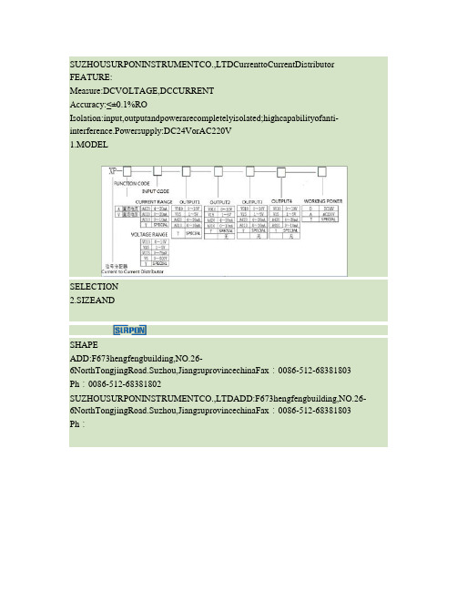
SUZHOUSURPONINSTRUMENTCO.,LTDCurrenttoCurrentDistributor FEATURE:Measure:DCVOLTAGE,DCCURRENTAccuracy:≤±0.1%ROIsolation:input,outputandpowerarecompletelyisolated;highcapabilityofanti-interference.Powersupply:DC24VorAC220V1.MODELSELECTION2.SIZEANDSHAPEADD:F673hengfengbuilding,NO.26-6NorthTongjingRoad.Suzhou,JiangsuprovincechinaFax:0086-512-68381803 Ph:0086-512-68381802SUZHOUSURPONINSTRUMENTCO.,LTDADD:F673hengfengbuilding,NO.26-6NorthTongjingRoad.Suzhou,JiangsuprovincechinaFax:0086-512-68381803 Ph:0086-512-68381802SUZHOUSURPONINSTRUMENTCO.,LTDADD:F673hengfengbuilding,NO.26-6NorthTongjingRoad.Suzhou,JiangsuprovincechinaFax:0086-512-68381803 Ph:0086-512-68381802模拟量信号隔离模块、模拟量信号隔离器产品型号:DATA-8301产品概述:模拟量信号隔离模块主要用于对各类4~20mA信号采集设备或控制设备进行隔离保护。
该隔离模块实现了电源、输入信号、输出信号的全面隔离,唐山平升模拟量信号隔离模块可有效消除串流、电磁、谐波等干扰信号、显著提高信号质量。
美国优倍 安全栅样本及技术手册
液晶型检测端(输入端)安全栅
单/双通道热电偶输入,单/双路输出··········································23
单/双通道热电阻输入,单/双路输出··········································25
&TECHINCSL BROCHURE
INDUSTRIAL INSTRUMENT BROCHURE
产品样本及技术手册
安全栅、温度变送器、隔离、配电器系列产品
中文版
Chinese Version
Ver.2007.11
C系列仪表
.
catalogue
引言/资质··············································封二
3ue引言资质封二安全栅的基本知识首页第一部分隔离安全栅安全栅的基本知识1安全栅通用技术指标5检测端输入端安全栅单双通道热电偶输入单双路输出6单双通道热电阻输入单双路输出8单双通道二三线制电流输入配电功能单双路输出10单双通道电流输入单双路输出12单双通道电压输入单双路输出14单双通道开关量输入开关量输出16单双通道频率量输入频率量电流输出18操作端输出端安全栅单双通道电流输入单双路输出19单双通道电压输入单双路输出20单双通道开关量输入开关量输出21液晶型检测端输入端安全栅单双通道热电偶输入单双路输出23单双通
液晶型智能配电器············································40
液晶型智能温度变送器··········································42
newpwr隔离器说明书
newpwr隔离器说明书第一章:产品概述第二章:产品特点1.高隔离性能:newpwr隔离器能够有效地隔离输入和输出之间的电气干扰,确保输出信号的稳定性和准确性。
2.宽工作温度范围:newpwr隔离器具备广泛的工作温度范围,适应各种复杂环境条件。
3.高可靠性:newpwr隔离器采用优质材料和结构设计,具有高可靠性和长寿命。
4.快速响应时间:newpwr隔离器能够迅速响应输入信号的变化,并在短时间内提供稳定的输出信号。
5.灵活的接口:newpwr隔离器提供多种输入和输出接口选项,支持不同类型的信号输入和输出。
第三章:产品安装1.安全操作:在安装newpwr隔离器之前,请确保断开电源,防止任何电气伤害。
2.安装位置选择:选择一个安全、通风良好的位置安装newpwr隔离器,避免与其他电气设备的干扰。
3.固定装置:通过合适的螺丝和固定装置将newpwr隔离器稳固地安装在所选位置上。
第四章:产品使用1.信号接入:将输入信号正确连接到newpwr隔离器的输入端口上,确保正确地接入接地线。
2.信号输出:将需要隔离的输出信号从newpwr隔离器的输出端口中获取,确保接收信号的设备或系统正常工作。
3.参数调整:根据具体使用要求,通过调整newpwr隔离器上的参数实现不同的隔离效果和信号处理方式。
4.额定功率使用:确保newpwr隔离器的工作功率不超过设备的额定功率,以防过载和故障。
第五章:产品维护1.定期检查:定期对newpwr隔离器进行检查,确保设备正常工作,无损坏和松动的部件。
2.清洁保养:使用干净、柔软的布轻轻清洁newpwr隔离器的外表面,避免使用化学溶剂。
3.防尘防湿:保持newpwr隔离器远离尘埃和潮湿环境,以避免损坏和电气故障。
第六章:产品故障排除1.自检功能:newpwr隔离器具备自动故障检测功能,当发生故障时会自动发出警报并采取相应的措施。
2.故障排除:在设备故障时,首先确保电源断开,然后检查接线是否正确,部件是否松动,故障是否由其他外部因素导致。
双通道数字隔离器 EVM 用户指南说明书
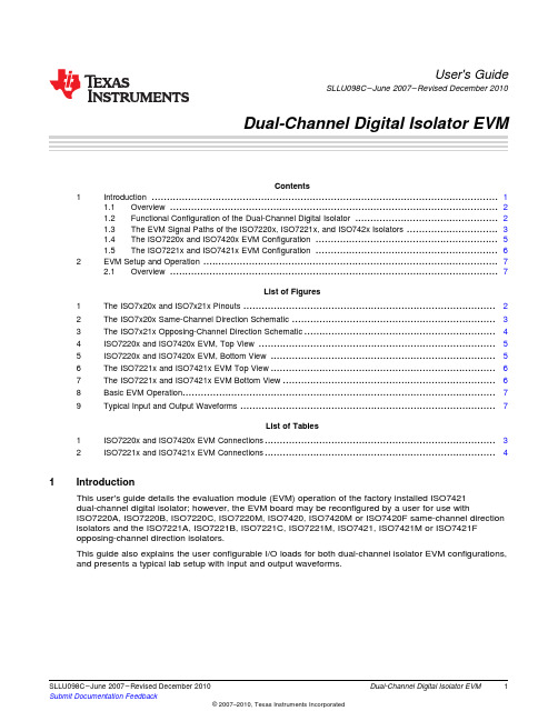
User's GuideSLLU098C–June2007–Revised December2010Dual-Channel Digital Isolator EVMContents1Introduction (1)1.1Overview (2)1.2Functional Configuration of the Dual-Channel Digital Isolator (2)1.3The EVM Signal Paths of the ISO7220x,ISO7221x,and ISO742x Isolators (3)1.4The ISO7220x and ISO7420x EVM Configuration (5)1.5The ISO7221x and ISO7421x EVM Configuration (6)2EVM Setup and Operation (7)2.1Overview (7)List of Figures1The ISO7x20x and ISO7x21x Pinouts (2)2The ISO7x20x Same-Channel Direction Schematic (3)3The ISO7x21x Opposing-Channel Direction Schematic (4)4ISO7220x and ISO7420x EVM,Top View (5)5ISO7220x and ISO7420x EVM,Bottom View (5)6The ISO7221x and ISO7421x EVM Top View (6)7The ISO7221x and ISO7421x EVM Bottom View (6)8Basic EVM Operation (7)9Typical Input and Output Waveforms (7)List of Tables1ISO7220x and ISO7420x EVM Connections (3)2ISO7221x and ISO7421x EVM Connections (4)1IntroductionThis user's guide details the evaluation module(EVM)operation of the factory installed ISO7421dual-channel digital isolator;however,the EVM board may be reconfigured by a user for use withISO7220A,ISO7220B,ISO7220C,ISO7220M,ISO7420,ISO7420M or ISO7420F same-channel direction isolators and the ISO7221A,ISO7221B,ISO7221C,ISO7221M,ISO7421,ISO7421M or ISO7421Fopposing-channel direction isolators.This guide also explains the user configurable I/O loads for both dual-channel isolator EVM configurations, and presents a typical lab setup with input and output waveforms.1 SLLU098C–June2007–Revised December2010Dual-Channel Digital Isolator EVM Submit Documentation FeedbackISO7x21xGND2Vcc2Vcc1GND1OUTB INA OUTA INB ISO7x20xGND2Vcc2Vcc1GND1OUTB INAOUTA INBIntroduction 1.1OverviewThe ISO7220x,ISO7221x,and ISO742X dual digital isolators have a logic input and output bufferseparated by a silicon oxide (SiO 2)insulation ed in conjunction with isolated power supplies,these devices block high voltage,isolate grounds,and prevent noise currents on a data bus or othercircuits from entering the local ground and interfering with or damaging sensitive circuitry.A binary input signal is conditioned,translated to a balanced signal,and then differentiated by thecapacitive isolation barrier.Across the isolation barrier,a differential comparator receives the logictransition information,then sets or resets a flip-flop and the output circuit accordingly.A periodic update pulse is sent across the barrier to ensure the proper dc level of the output.If this dc-refresh pulse is not received for more than 4m s,the input is assumed to be unpowered or not functional,and the failsafecircuit drives the output to a logic-high state.For ISO7420F and ISO7421F,the failsafe circuit drives the output to a logic-low state.CAUTIONNote that although these devices provide galvanic isolation of up to 4000V,thisEVM cannot be used for isolation voltage testing.It is designed for theexamination of device operating parameters only and will be damaged if highvoltage (>5.5V)is applied anywhere in the circuit.1.2Functional Configuration of the Dual-Channel Digital IsolatorThe pin-outs of the dual-channel digital isolators are displayed in Figure 1.The EVM comes with anISO7421installed;however,the user may reconfigure the EVM for use with any of the footprints.Figure 1.The ISO7x20x and ISO7x21x PinoutsThe ISO7220A,ISO7220B,ISO7220C,ISO7221A,ISO7221B and ISO7221C have TTL input thresholds and an input noise filter that prevents transient pulses of up to 2ns in duration from being passed to the output of the device.The ISO7220M and ISO7221M have a CMOS Vcc/2input threshold,but do not have the noise filter and the additional propagation delay.2Dual-Channel Digital Isolator EVM SLLU098C–June 2007–Revised December 2010Submit Documentation FeedbackV CC1(Banana Jack P1)V CC2(Banana Jack P2)GND1(Banana Jack P3)GND2(Banana Jack P4) Introduction1.3The EVM Signal Paths of the ISO7220x,ISO7221x,and ISO742x IsolatorsThis multifunctional EVM is designed with signal paths shown in Figure 1,Figure 2,and Figure 3for the evaluation of the ISO7220x and ISO7221x dual-channel isolators.Figure 2.The ISO7x20x Same-Channel Direction SchematicTable 1.ISO7220x and ISO7420x EVM ConnectionsConnectionLabel Description J1SMA connector to the INB input,pin 3J2SMA connector to the OUTB output,pin 6J3SMA connector to the INA input,pin 2J4SMA connector to the OUTA output,pin 7P1V CC1Input power supply banana jack P2V CC2Output power supply banana jack P3GND1Input power ground connection banana jack P4GND2Output power ground connection banana jack JMP13-pin jumper V CC1,input,GND1JMP23-pin jumper used to monitor OUTB with scope probe JMP33-pin jumper –V CC1,input,GND1JMP43-pin jumper used to monitor OUTA with scope probe3SLLU098C–June 2007–Revised December 2010Dual-Channel Digital Isolator EVM Submit Documentation FeedbackIntroduction V CC1(Banana Jack P1)V CC2(Banana Jack P2)GND1(Banana Jack P3)GND2(Banana Jack P4)Figure3.The ISO7x21x Opposing-Channel Direction SchematicTable2.ISO7221x and ISO7421x EVM ConnectionsConnection Label DescriptionJ1SMA connector to the INB input,pin3J2SMA connector to the OUTB output,pin6J3SMA connector to the OUTA output,pin2J4SMA connector to the INA input,pin7P1V CC1Input power supply banana jackP2V CC2Output power supply banana jackP3GND1Input power ground connection banana jackP4GND2Output power ground connection banana jackJMP13-pin jumper V CC1,input,GND1JMP23-pin jumper used to monitor OUTB with scope probeJMP33-pin jumper used to monitor OUTA with scope probeJMP43-pin jumper V CC2,input,GND24Dual-Channel Digital Isolator EVM SLLU098C–June2007–Revised December2010Submit Documentation Feedback Introduction1.4The ISO7220x and ISO7420x EVM ConfigurationThe ISO7220x EVM configuration has SMA connectors (J1and J3)set up as the input to the INA (pin 2)and INB (pin 3)of the ISO7220M in Figure 1and Figure 2.R2and R8are 0-Ωinput series resistorsshown in Figure 4,and are located next to the J1and J3input connectors.R1and R5are 50-Ωresistors from each input to ground,and are located on the bottom of the board as shown in Figure 5.Figure 4.ISO7220x and ISO7420x EVM,Top ViewThe output channel configuration of the ISO7220x EVM has the OUTA (pin 7)and OUTB (pin 6)ofFigure 1and Figure 2connected to SMA connector (J2and J4)through 0-Ωseries resistor,R4and R6.Figure 5.ISO7220x and ISO7420x EVM,Bottom ViewThe pads for R3,R7,C1,C12,C13and C14are available on the bottom of the EVM for varied loadingconditions if desired by a user.5SLLU098C–June 2007–Revised December 2010Dual-Channel Digital Isolator EVM Submit Documentation FeedbackIntroduction 1.5The ISO7221x and ISO7421x EVM ConfigurationThe ISO7221x EVM configuration has SMA connectors (J4and J1)set up as the input to the INA (pin 7)and INB (pin 3)of the ISO7221x in Figure 1and Figure 3.R2and R6are 0-Ωinput series resistors shown in Figure 6,and are located next to the J1and J4input connectors.Figure 6.The ISO7221x and ISO7421x EVM Top ViewThe output channel configuration of the ISO7221x EVM has the OUTA (pin 2)and OUTB (pin 6)ofFigure 1and Figure 3connected to SMA connector (J3and J2)through 0-Ωseries resistor,R8and R4.R1and R7are 50-Ωresistors from each input to ground on the bottom of the board shown in Figure 7.Figure 7.The ISO7221x and ISO7421x EVM Bottom ViewThe pads for R3,R5,C1,C12,C13and C14are available on the bottom of the EVM for varied loading conditions if desired by a user.6Dual-Channel Digital Isolator EVM SLLU098C–June 2007–Revised December 2010Submit Documentation Feedback EVM Setup and Operation 2EVM Setup and OperationThis section includes the setup and operation of the EVM for parameter performance evaluation.Typical waveforms are included.2.1OverviewThe basic setup in Figure 5has the two power supplies required to evaluate isolator performance with3.3-V on one side and 3.3-V on the other.If both sides are to be evaluated at the same supply voltage,only one power supply is required and can be used to power both sides of the EVM.CAUTIONNote that this EVM is for operating parameter performance evaluation only andnot designed for isolation voltage testing.Any voltage applied above the 5.5-Vmaximum recommended operating voltage of the digital isolators will damagethe EVM.Figure 8.Basic EVM OperationIn Figure 8,the J3input to the EVM is a 20MHz pulse displayed on channel 1in Figure 9.The J4output of the EVM is channel 2.Figure 9.Typical Input and Output Waveforms7SLLU098C–June 2007–Revised December 2010Dual-Channel Digital Isolator EVM Submit Documentation FeedbackEVALUATION BOARD/KIT IMPORTANT NOTICETexas Instruments(TI)provides the enclosed product(s)under the following conditions:This evaluation board/kit is intended for use for ENGINEERING DEVELOPMENT,DEMONSTRATION,OR EVALUATION PURPOSES ONLY and is not considered by TI to be a finished end-product fit for general consumer use.Persons handling the product(s)must have electronics training and observe good engineering practice standards.As such,the goods being provided are not intended to be complete in terms of required design-,marketing-,and/or manufacturing-related protective considerations,including product safety and environmental measures typically found in end products that incorporate such semiconductor components or circuit boards.This evaluation board/kit does not fall within the scope of the European Union directives regarding electromagnetic compatibility,restricted substances(RoHS),recycling (WEEE),FCC,CE or UL,and therefore may not meet the technical requirements of these directives or other related directives.Should this evaluation board/kit not meet the specifications indicated in the User’s Guide,the board/kit may be returned within30days from the date of delivery for a full refund.THE FOREGOING WARRANTY IS THE EXCLUSIVE WARRANTY MADE BY SELLER TO BUYER AND IS IN LIEU OF ALL OTHER WARRANTIES,EXPRESSED,IMPLIED,OR STATUTORY,INCLUDING ANY WARRANTY OF MERCHANTABILITY OR FITNESS FOR ANY PARTICULAR PURPOSE.The user assumes all responsibility and liability for proper and safe handling of the goods.Further,the user indemnifies TI from all claims arising from the handling or use of the goods.Due to the open construction of the product,it is the user’s responsibility to take any and all appropriate precautions with regard to electrostatic discharge.EXCEPT TO THE EXTENT OF THE INDEMNITY SET FORTH ABOVE,NEITHER PARTY SHALL BE LIABLE TO THE OTHER FOR ANY INDIRECT,SPECIAL,INCIDENTAL,OR CONSEQUENTIAL DAMAGES.TI currently deals with a variety of customers for products,and therefore our arrangement with the user is not exclusive.TI assumes no liability for applications assistance,customer product design,software performance,or infringement of patents or services described herein.Please read the User’s Guide and,specifically,the Warnings and Restrictions notice in the User’s Guide prior to handling the product.This notice contains important safety information about temperatures and voltages.For additional information on TI’s environmental and/or safety programs,please contact the TI application engineer or visit /esh.No license is granted under any patent right or other intellectual property right of TI covering or relating to any machine,process,or combination in which such TI products or services might be or are used.FCC WarningThis evaluation board/kit is intended for use for ENGINEERING DEVELOPMENT,DEMONSTRATION,OR EVALUATION PURPOSES ONLY and is not considered by TI to be a finished end-product fit for general consumer use.It generates,uses,and can radiate radio frequency energy and has not been tested for compliance with the limits of computing devices pursuant to part15of FCC rules,which are designed to provide reasonable protection against radio frequency interference.Operation of this equipment in other environments may cause interference with radio communications,in which case the user at his own expense will be required to take whatever measures may be required to correct this interference.Mailing Address:Texas Instruments,Post Office Box655303,Dallas,Texas75265Copyright©2009,Texas Instruments IncorporatedEVM WARNINGS AND RESTRICTIONSIt is important to operate this EVM within the input voltage range of0V to5.5V and the output voltage range of0V to6V.Exceeding the specified input range may cause unexpected operation and/or irreversible damage to the EVM.If there are questions concerning the input range,please contact a TI field representative prior to connecting the input power.Applying loads outside of the specified output range may result in unintended operation and/or possible permanent damage to the EVM. Please consult the EVM User's Guide prior to connecting any load to the EVM output.If there is uncertainty as to the load specification, please contact a TI field representative.During normal operation,some circuit components may have case temperatures greater than85°C.The EVM is designed to operate properly with certain components above85°C as long as the input and output ranges are maintained.These components include but are not limited to linear regulators,switching transistors,pass transistors,and current sense resistors.These types of devices can be identified using the EVM schematic located in the EVM User's Guide.When placing measurement probes near these devices during operation, please be aware that these devices may be very warm to the touch.Mailing Address:Texas Instruments,Post Office Box655303,Dallas,Texas75265Copyright©2009,Texas Instruments IncorporatedIMPORTANT NOTICETexas Instruments Incorporated and its subsidiaries(TI)reserve the right to make corrections,modifications,enhancements,improvements, and other changes to its products and services at any time and to discontinue any product or service without notice.Customers should obtain the latest relevant information before placing orders and should verify that such information is current and complete.All products are sold subject to TI’s terms and conditions of sale supplied at the time of order acknowledgment.TI warrants performance of its hardware products to the specifications applicable at the time of sale in accordance with TI’s standard warranty.Testing and other quality control techniques are used to the extent TI deems necessary to support this warranty.Except where mandated by government requirements,testing of all parameters of each product is not necessarily performed.TI assumes no liability for applications assistance or customer product design.Customers are responsible for their products and applications using TI components.To minimize the risks associated with customer products and applications,customers should provide adequate design and operating safeguards.TI does not warrant or represent that any license,either express or implied,is granted under any TI patent right,copyright,mask work right, or other TI intellectual property right relating to any combination,machine,or process in which TI products or services are rmation published by TI regarding third-party products or services does not constitute a license from TI to use such products or services or a warranty or endorsement e of such information may require a license from a third party under the patents or other intellectual property of the third party,or a license from TI under the patents or other intellectual property of TI.Reproduction of TI information in TI data books or data sheets is permissible only if reproduction is without alteration and is accompanied by all associated warranties,conditions,limitations,and notices.Reproduction of this information with alteration is an unfair and deceptive business practice.TI is not responsible or liable for such altered rmation of third parties may be subject to additional restrictions.Resale of TI products or services with statements different from or beyond the parameters stated by TI for that product or service voids all express and any implied warranties for the associated TI product or service and is an unfair and deceptive business practice.TI is not responsible or liable for any such statements.TI products are not authorized for use in safety-critical applications(such as life support)where a failure of the TI product would reasonably be expected to cause severe personal injury or death,unless officers of the parties have executed an agreement specifically governing such use.Buyers represent that they have all necessary expertise in the safety and regulatory ramifications of their applications,and acknowledge and agree that they are solely responsible for all legal,regulatory and safety-related requirements concerning their products and any use of TI products in such safety-critical applications,notwithstanding any applications-related information or support that may be provided by TI.Further,Buyers must fully indemnify TI and its representatives against any damages arising out of the use of TI products in such safety-critical applications.TI products are neither designed nor intended for use in military/aerospace applications or environments unless the TI products are specifically designated by TI as military-grade or"enhanced plastic."Only products designated by TI as military-grade meet military specifications.Buyers acknowledge and agree that any such use of TI products which TI has not designated as military-grade is solely at the Buyer's risk,and that they are solely responsible for compliance with all legal and regulatory requirements in connection with such use. TI products are neither designed nor intended for use in automotive applications or environments unless the specific TI products are designated by TI as compliant with ISO/TS16949requirements.Buyers acknowledge and agree that,if they use any non-designated products in automotive applications,TI will not be responsible for any failure to meet such requirements.Following are URLs where you can obtain information on other Texas Instruments products and application solutions:Products ApplicationsAmplifiers Audio /audioData Converters Automotive /automotiveDLP®Products Communications and /communicationsTelecomDSP Computers and /computersPeripheralsClocks and Timers /clocks Consumer Electronics /consumer-appsInterface Energy /energyLogic Industrial /industrialPower Mgmt Medical /medicalMicrocontrollers Security /securityRFID Space,Avionics&/space-avionics-defenseDefenseRF/IF and ZigBee®Solutions /lprf Video and Imaging /videoWireless /wireless-appsMailing Address:Texas Instruments,Post Office Box655303,Dallas,Texas75265Copyright©2010,Texas Instruments Incorporated。
苏州迅鹏信号隔离器英文说明书(最全)word资料
SUZHOUSURPONINSTRUMENTCO.,LTDCurrenttoCurrentDistributor FEATURE:Measure:DCVOLTAGE,DCCURRENTAccuracy:≤±0.1%ROIsolation:input,outputandpowerarecompletelyisolated;highcapabilityofanti-interference.Powersupply:DC24VorAC220V1.MODELSELECTION2.SIZEANDSHAPEADD:F673hengfengbuilding,NO.26-6NorthTongjingRoad.Suzhou,JiangsuprovincechinaFax:0086-512-68381803 Ph:0086-512-68381802SUZHOUSURPONINSTRUMENTCO.,LTDADD:F673hengfengbuilding,NO.26-6NorthTongjingRoad.Suzhou,JiangsuprovincechinaFax:0086-512-68381803 Ph:0086-512-68381802SUZHOUSURPONINSTRUMENTCO.,LTDADD:F673hengfengbuilding,NO.26-6NorthTongjingRoad.Suzhou,JiangsuprovincechinaFax:0086-512-68381803 Ph:0086-512-68381802模拟量信号隔离模块、模拟量信号隔离器产品型号:DATA-8301产品概述:模拟量信号隔离模块主要用于对各类4~20mA信号采集设备或控制设备进行隔离保护。
该隔离模块实现了电源、输入信号、输出信号的全面隔离,唐山平升模拟量信号隔离模块可有效消除串流、电磁、谐波等干扰信号、显著提高信号质量。
M-System M5YV 电源隔离器说明书

BEFORE USE ....Thank you for choosing M-System. Before use, please check contents of the package you received as outlined below .If you have any problems or questions with the product, please contact M-System’s Sales Office or representatives. ■PACKAGE INCLUDES:Isolator .................................................................................(1)Sealing label (option /VN) .........................................(1 sheet) ■MODEL NO.Confirm Model No. marking on the product to be exactly what you ordered.■INSTRUCTION MANUALThis manual describes necessary points of caution when you use this product, including installation, connection and basic maintenance procedures.POINTS OF CAUTION■CONFORMITY WITH EU DIRECTIVES OR UK LEGISLATION • The equipment must be mounted inside a panel.• Insert a noise filter for the power source, input and out-put connected to the unit. COSEL Noise Filter Model NAC-06-472, TDK Noise Filter Model ZCAT 3035-1330 or equivalent is recommended.• The actual installation environments such as panel con-figurations, connected devices, connected wires, may affect the protection level of this unit when it is integrated in a panel system. The user may have to review the CE or UKCA requirements in regard to the whole system and employ additional protective measures to ensure the CE or UKCA conformity . ■POWER INPUT RATING & OPERATIONAL RANGE• Locate the power input rating marked on the product and confirm its operational range as indicated below:24V DC rating: 24V ±10%, approx. 2W ■GENERAL PRECAUTIONS• Before you remove the unit or mount it, turn off the power supply and input signal for safety . ■ENVIRONMENT • Indoor use.• When heavy dust or metal particles are present in the air, install the unit inside proper housing with sufficient ventilation.• Do not install the unit where it is subjected to continuous vibration. Do not subject the unit to physical impact.• Environmental temperature must be within -5 to +55°C (23 to 131°F) with relative humidity within 0 to 90% RH in order to ensure adequate life span and operation. ■WIRING• Do not install cables close to noise sources (relay drive cable, high frequency line, etc.).noises are present. Do not install them in the same duct.• Install lightning surge protectors for those wires connect-ed to remote locations. For 24V DC power supply line, choose a surge protector with its maximum surge volt-age 40V or less between lines. Recommended M-System model: MDP-D24.■AND ....• The unit is designed to function as soon as power is sup-plied, however, a warm up for 10 minutes is required for satisfying complete performance described in the data sheet.COMPONENT IDENTIFICATIONINSTALLATIONSet the unit so that its DIN rail adapter is at the bottom. ■MOUNTING THE UNIT ON A DIN RAILA) Hang the upper hook at the rear side of unit on the DIN rail.B) Push in the lower in keeping pressing the unit to the DINrail.■REMOVING THE UNITA)Push down the DIN rail adaptor using a minus screw-driver.B) Pull out the lower part of the unit.C) Remove the upper part from the DIN rail.056 222 38 18SEN TRONIC AGM5YVTERMINAL CONNECTIONSConnect the unit as in the diagram below or refer to the con-nection diagram on the front of the unit. ■EXTERNAL DIMENSIONS unit: mm [inch]•When mounting, no extra space is needed between units.■CONNECTION DIAGRAM+–+–+–WIRING INSTRUCTIONS■SCREW TERMINAL Torque: 0.8 N·mCHECKING1)Terminal wiring: Check that all cables are correctly con-nected according to the connection diagram.2)Power input voltage: Check voltage across the terminal 7 – 8 with a multimeter.3)Input: Check that the input signal is within 0 – 100% of the full-scale.4)Output: Check that the load resistance meets the de-scribed specifications.ADJUSTMENT PROCEDUREThis unit is calibrated at the factory to meet the ordered specifications, therefore you usually do not need any cali-bration.For matching the signal to a receiving instrument or in case of regular calibration, adjust the output as explained in the following.■HOW TO CALIBRATE THE OUTPUT SIGNALUse a signal source and measuring instruments of sufficient accuracy level. Turn the power supply on and warm up for more than 10 minutes.1)ZERO: Apply 0% input and adjust output to 0%.2)SPAN: Apply 100% input and adjust output to 100%.3)Check ZERO adjustment again with 0% input.4)When ZERO value is changed, repeat the above proce-dure 1) – 3).Note: Remove the sealing label for /VN option.MAINTENANCERegular calibration procedure is explained below:■CALIBRATIONWarm up the unit for at least 10 minutes. Apply 0%, 25%,50%, 75% and 100% input signal. Check that the output signal for the respective input signal remains within accu-racy described in the data sheet. When the output is out of tolerance, recalibrate the unit according to the “ADJUST-MENT PROCEDURE” explained earlier.LIGHTNING SURGE PROTECTIONM-System offers a series of lightning surge protector for protection against induced lightning surges. Please contact M-System to choose appropriate models.056 222 38 18*********************SEN TRONIC AG。
威德米勒 ACT20X-2HTI-2SAO-S 2-通道火花安全电流输出隔离器说明书

GermanyFon: +49 5231 14-0Fax: +49 5231 14-292083TypeACT20X-2HTI-2SAO-S Order No.8965480000Version ACT20X, EX signal isolating converter, 2-channel versionGTIN (EAN)4032248785094Qty.1 pc(s).The ACT20X-HTI-SAO / 2HTI-2SAO temperaturetransducers record temperatures from PT100 sensors and thermocouples from Ex zone 0. Current loops from 0(4) to 20 mA can also be connected on the input side.On the output side, there are active and passive current loops available for the safe zone.Integrated alarm contacts issue an alert in the event of a malfunction; this makes troubleshooting easier and increases system availability.The rail-mounted current output isolators are optionally available in one- or two-channel versions.With 11 mm width per channel, the devices need little space in the electrical cabinet.GermanyFon: +49 5231 14-0Fax: +49 5231 Width 22.5 mm Height 117.2 mm Depth113.6 mmNet weight180 gHumidity0...95 % (no condensation)Operating temperature -20 °C...60 °CStorage temperature-20 °C...85 °CMTBF111 YearsSIL in compliance with IEC 615082intrinsically safe circuit,RTD, TC, DC (mA)PT100, PT250, PT300,PT400, PT500, PT1000,Ni50, Ni100, Ni120,Ni1000, Thermocouples:B, E, J, K, N, R, S, T ;in compliance with IEC 60584-1 and L,U in compliance with DIN43710Temperature input range ConfigurableInput current0...20 mA, 4…20mA Input resistance, current20 Ω + PTC 50 ΩLine resistance in measuring circuit≤ 50 Ω(U B - 3.5) / 0.023 Aor passive (as current sink)Influence of load resistance ≤ 0.01% of span / 100 ΩOutput signal limit 3.8…20.5 mA / 0…20.5mA (dependent on range)Output current0…23 mA, configurable:0…20 / 4…20 / 20…0 /20…4 mA, configurable downscale (3.5 mA) ⁄upscale (23 mA) @ errorload impedance current≤ 600 ΩRelay, 1 NC (voltage-free)(safe area)≤ 32 V AC / 32 V DC (Zone 2)Continuous current≤ 0.5 A AC / 0.3 A DC(safe zone), ≤ 0.5 A AC / 1A DC ( Zone 2)Power rating≤ 62.5 VA / 32 W (safe area)≤ 16 VA / 32 W (Zone 2)DTM alternatively usable with PACT ware ™19.2 – 31.2 V DCType of connection Screw connection,Removable terminal blockPower consumption ≤ 3 W (2 channels)Protection degreeIP 20Humidity0...95 % (no condensation)GermanyFon: +49 5231 14-0Fax: +49 5231 14-292083EMC standards DIN EN 61326 Insulation voltage 2.6 kV (input / output) Rated voltage300 V2-wire supply 3.5…26 V DC Output current (current loop)4…20 mALoad resistance(U B - 3.5) / 0.023 A Influence of load resistance ≤ 0.01% of span / 100 ΩVoltage U08.7 V DC Current I018.4 mAPower P040 mWDevice type B Hardware fault tolerance (HFT)0T proof 3 Years Safety category SIL 2Probability of outage PFH 6.1 x 10⁻⁸ h-1Demand (PFD avg)proofyear), 6.5 x 10⁻⁴ (T proof = 2years), 1.41 x 10⁻⁴ (T proof =5 years)Removable terminal block0.4 Nm Tightening torque, max.0.6 Nm Clamping range, rated connection 2.5 mm²Clamping range, rated connection, min.0.5 mm² Clamping range, rated connection, max.2.5 mm²UL certificate E337701.pdfATEX certificate10ATEX0020X.pdf IEC Ex certificate IECEx certification Certificate No. (ATEX)KEMA10ATEX0020X Certificate No. (IECEX)IECEXKEM09.0092XETIM 3.0EC002479 ETIM 4.0EC002479ETIM 5.0EC002479 ETIM 6.0EC002479 UNSPSC30-21-18-01 eClass 5.127-21-01-07 eClass 6.227-21-01-07 eClass 7.127-21-01-07 eClass 8.127-21-01-07 eClass 9.027-21-01-07Descriptive text ordering data CBX200 USB configuration adapter - 8978580000GermanyFon: +49 5231 14-0Fax: +49 5231 14-292083ROHS ConformSIL PAPER SIL certificate3-D modelFDT/DTM Software WI- ManagerManual Manual ACT20X- Hardware german / englishPackage insert instruction sheet.pdfQuick reference guide Quick Start Guide to install FDT/DTM SoftwareSIL PAPER SIL certificateSafety manual Manual "functional safety"Software Weidmueller DTM-LibraryWI Manager manual Manual WI-Manager german/englishDeclaration of Conformity Declaration of Conformity.pdfEPLAN8965480000.ema3-D modelGermanyFon: +49 5231 14-0Fax: +49 5231 14-292083application schematicScreenshot configuration with FDT /DTM Screenshot of current inputconfiguration with FDT/DTM softwareScreenshot of current input configuration with FDT/DTM softwareScreenshot of temperature input configuration with FDT/DTM softwareGermanyFon: +49 5231 14-0Fax: +49 5231 14-292083Screenshot of current outputconfiguration with FDT/DTM softwareUnited Arab Emirates Weidmuller Middle East FZE Warehouse Q3-79SAIF-ZoneP.O. BOX 8591SharjahTelephone number +971 65572723Fax number +971 65572724************************AngolaPlease contact Phambili Interface South AfricaArgentina ARCPI SABauness 2660C1431DOF Buenos Aires Telephone number +54 11 4523 8008Fax number +54 11 4522 0546************.ar .arAustriaAT Weidmüller GmbHIZ NOE Süd Straße 2b, Obj M 592355 Wiener NeudorfTelephone number +43 2236 67080Fax number +43 2236 6708-899************************* AustraliaAUWeidmüller Pty. Ltd.PO BOX 6944Huntingwood 2148Huntingwood Drive 43Huntingwood NSW 2148Telephone number +61 2 9671 9999Fax number +61 2 9671 9911*******************.au .au AzerbaijanAZRepresentative Office Rashad MahmudovDemirchi Tower, 4th floor 37, Khojali ave.AZ 1025 BakuTelephone number +994 12 488 80 36Fax number +994 12 488 80 37rashad.mahmudov@Bosnia and Herzegovina BABIG electric d.o.oMladena Stojanovića 117A 78000 Banja LukaTelephone number +387 51926277Fax number +387 51926277********************www.bigelectric.baPlease contactour Representative Office Weidmüller Interface GmbH & Co. KG Serbia orBelgiumBEWeidmüller Benelux B. V.Mechelsesteenweg 519 bus 6 en 71930 NossegemTelephone number +32 2 752 40 70Fax number +32 2 751 36 06*******************www.weidmueller.be BulgariaBGWeid-Bul EOODBul. “Kliment Ohridski” 131756 SofiaTelephone number +359 2 963 2560Fax number +359 2 963 1098*****************BahrainKhayber Trading Company P.O Box 1976ManamaTelephone number +973 720747Fax number +973 720331*******************.bh BrazilWeidmuller Conexel do Brasil Conexões Elétricas Ltda.Av. Presidente Juscelino, 642 - PiraporinhaDiadema, São Paulo 09950-370Telephone number +55 (11) 4366-9600Fax number +55 (11) 4362-1677**********************.br.br Botswana Please contact Phambili Interface South AfricaBelarusBYTECHNIKON Ltd.Nezavisimosti pr. 177-9220125 MinskTelephone number +375 17 393-11-77Fax number +375 17 3930080***************CanadaCAW Interconnections Canada Inc.10 Spy CourtMarkham Ontario L3R 5H6Telephone number +1 (905) 475-1507 Ext. 9836Fax number +1 (905) 475-2798*********************www.weidmuller.ca CongoPlease contact Phambili Interface South AfricaSwitzerlandCHWeidmüller Schweiz AG Rundbuckstraße 28212 Neuhausen am Rheinfall SHTelephone number +41 52 674 07 07Fax number +41 52 674 07 08*******************www.weidmueller.ch CLChileATS - INTECHMaría Luisa Santander 0475SantiagoProvidencia 7500859Telephone number +56 2 341 1271Fax number +56 2 341 1275********************CPI CHILE LTDAAv. Presidente Frei Montalva 6001, 47 complejo el cortijo Santiago - ConchaliTelephone number +562 963 8440Fax number +562 963 8440***************www.cpichile.clChinaCNWeidmüller Interface (Shanghai) Co. Ltd.100 Yutong Road25 F, BM Intercontinental Business Center 200070 ShanghaiTelephone number +86 21-22195008Fax number +86 512-68417505customer.hotline@ ColombiaAutomatización Avanzada S. A.Carrera 97 No., 24 c - 23 Bodega 4110911 Bogotá-D.C.Telephone number +57 (1) 547-8510Fax number +57 (1) 422-3044comercial@ www. Costa Rica CRELVATRON S. A.la Uruca 400 Norte Banco Costa RicaSan Jose Costa RicaTelephone number +506 2961-060Fax number +506 5200-609***********************Czech Republic CZWeidmüller s.r.o.Lomnického 5/1705140 00 Praha 4Telephone number +420 244 001 400Fax number +420 244 001 499*********************www.weidmueller.czGermanyDEWeidmüller GmbH & Co. KG Ohmstraße 932758 Detmold Postfach 30 5432720 DetmoldTelephone number +49 5231 1428-0Fax number +49 5231 14-292083**************************www.weidmueller.de DenmarkDKWeidmüller Danmark Vallensbækvej 18A 2605 BrøndbyTelephone number +45 27747800**************************www.weidmuller.dkAlgeriaSARL INTER ELECTRIC1a Angles des Rues Okba Ibn Nafaa et Hassi Beida 2300 AnnabaTelephone number Fax number**************************EcuadorECElsystec S. A., Electricidad Sistemas y TecnologíaVasco de Contreras N35-251 y MañoscaQuito - PichinchaTelephone number +593 22456510Fax number +593 22456755*******************.net EstoniaEESoots Interface OÜPärnu mnt 14211317 TallinnTelephone number +372 609 6933Fax number**********************www.sootsinterface.eePlease contactour Representative Office Weidmüller Interface GmbH & Co. KG Latvia orEgyptEGStandard Electric (OMEGA)1, Abdelhamid Badawy Street Heliopolis CairoTelephone number +202 21805111Fax number +202 21805600****************SpainWeidmüller, S. A.Narcis Monturiol 11-13, Pol. Ind. Sudoeste 8960 Sant Just Desvern - BarcelonaTelephone number +34 934 803 386Fax number +34 933 718 055************************www.weidmuller.esFinlandFIWeidmüller Suomi,Weidmüller Aktiebolagetin sivuliikeKoy Plaza Vivace Äyritie 8CFI 1510 VantaaTelephone number +358 20 7351300Fax number +358 800 114 667****************************www.weidmuller.fiFranceFR Weidmüller E. U. R. L.12, Chaussée Jules César BP 263 Osny95523 Cergy-Pontoise Cedex Telephone number +33 1 34 24 55 00Fax number +33 1 34 24 55 01******************Great Britain GBWeidmüller Ltd.Klippon HouseCenturion Court Office Park, Meridian East, Meridian Business Park Leicester LE19 1TPTelephone number +44 116 282 3470Fax number +44 116 289 3582***********************.uk GeorgiaGE Please contactour Representative Office Rashad MahmudovAzerbaijan.GhanaPlease contactWeidmüller Interface GmbH & Co. KG South AfricaGreeceGRG.A. SolutionsIppokratous 11 Metamorfosi 144 52 AthenTelephone number +30 210 2823233Fax number +30 210 2823233******************www.weidmuller.grGuatemalaGTPrestelectro, Prestegard Electro, S.A.Avenida Petapa 44-22, Zona 12Guatemala CityTelephone number +502 2442-3346Fax number +502 2476-8945***********************Hong KongHKWeidmuller (Hong Kong) Limited Co. Ltd.Unit 1617, Metropolis Tower No. 10 Metropolis Drive, Hunghom, KowloonTelephone number +852 3154 8088Fax number +852 *******************************.hk CroatiaHRElektroPARTNER d.o.o.Slavonska avenija 24/6HR-10000 ZagrebTelephone number +385 (1) 6184 793Fax number +385 (1) 6184 795***********************.hr HungaryWeidmüller Kereskedelmi Kft.Budapest Gubacsi út 6.1097Telephone number +36 1 382 7700Fax number +36 1 382 7701*******************www.weidmueller.hu IndonesiaPT. Nego ElectrindoRuko Mega Grosir Cempaka Mas Blok I No. 20 – 22Jakarta 10640Telephone number +62 21 42882255Fax number +62 21 42882266***********************.id IrelandPlease contact Weidmüller Ltd.Great BritainILIsraelA. U. Shay Ltd.23/25, Embar Street 49222 Petach-Tikva P.O. Box 1 00 4949222 Petach-TikvaTelephone number +972 3-923-3601Fax number +972 3-923-4601******************* ATEKA Ltd.4, Ha Tavor lane Industrial area Segula49691 Petach-Tikva P.O. Box 4710Petach-TikvaTelephone number +972 73-200-1311Fax number +972 3-924 4245******************.il www.ateka.co.ilIndiaINRepresentative OfficeWeidmüller Electronics India Pvt. Ltd.12th Lane North Avenue, Opp Joggers Park,Kalyani Nagar, Pune 411 006Telephone number +91 20-41290090*********************** IcelandISSamey Automation Center Lyngas 13210 GaroabaerTelephone number +354 510 5200Fax number +354 5 10 5201**************www.samey.isItalyITWeidmüller S. r.l.Via Albert Einstein 420092 Cinisello Balsamo MilanoTelephone number +39 02 660681Fax number +39 02 6124945************************www.weidmuller.it JamaicaPlease contactW Interconnections Inc.United StatesJordanJOTrans Jordan for Electro PO Box 33 06 07AmmanTelephone number +962 6 533 2020Fax number +962 6 533 5800**********************Addresses worldwide Let’s connect.JapanNihon Weidmüller Co. Ltd.Sphere Tower Tennoz 2-2-8Higashi-Shinagawa, Shinagawa-ku Tokyo140-0002Telephone number +81 3 6711 5300Fax number +81 3 6711 5333weidmullerjapan@weidmuller.co.jpwww.weidmuller.co.jp KenyaPlease contactour Representative Office Weidmüller Interface GmbH & Co. KG South Africa.KoreaWeidmuller Korea Co. Ltd.9th floor, Wonbang B/DSamseong 2-Dong, Gangnam-GuSeoul 143-42Telephone number +82 2-516-0003Fax number +82 2-516-0090******************.krwww.weidmuller.co.kr KuwaitKana Controls General Trading & Contracting Co. W. L. L.Al Rai Industrial Area, Plot 28-30, St. 3113016 Safat B.P. 25593Telephone number +965 4741373Fax number +965 4741537*********************Kazakhstan Please contact Weidmüller GroupRussiaLebanonProgress Engineering & Trading Enterprises Al Nahr Street Beirut 11-1111Telephone number +961 1 444 664Fax number +961 1 561 880*****************.lb Lithuania LTELEKTROS IRANGA Tinklu g. 29 aLT-5319 PanevezysTelephone number +370 (45) 582 828Fax number ****************Please contactour Representative Office Weidmüller Interface GmbH & Co. KG LatviaorLuxembourg Please contactWeidmüller Benelux B. herlandsLVLatvia SIA Abi4Daugavgrivas 31b Riga, LV-1007Telephone number +371 674 70999Fax number +371 676 24562**************Representative OfficeWeidmüller Interface GmbH & Co. KGUdens str. 12-118Riga, LV-1007Telephone number +371 29254766Fax number +371 674 65637Ilgonis.rudaks@Morocco Sofimed137, Bd Moulay Ismail Roches Noires20290 Casablanca Telephone number Fax number************************MoldovaMDBERHORD A & D srl79/1, str. Milescu Spartaru MD-2075 Chisinau MoldovaTelephone number +373 (22) 815002Fax number +373 (22) 815007********************* Montenegro MEPlease contactour Representative Office Weidmüller Interface GmbH & Co. KGSerbia.Madagascar Please contact Phambili Interface South AfricaMacedonia MKELEKTRO - SMK dooelUL. III Makedonska brigada b.b.1000 SkopjeTelephone number +389 22460295Fax number*************************.mkPlease contactour Representative Office Weidmüller Interface GmbH & Co. KG Serbia orMaltaMTE. S. S., Electrical Supplies & Services Ltd.San Gwakkin Road MriehelTelephone number +356 21255777Fax number +356 21255999********************.mtMauritiusMUMubelo Electrical Ltd.Office 26, Gateway building, St Jean Road Quatre Bornes MauritiusTelephone number +230 4670989Fax number +230 4654051************************MalawiMWPlease contactour Representative Office Weidmüller Interface GmbH & Co. KG South Africa.MexicoMXW Interconnections S. A. DE C. V.Blvd. Hermanos Serdán 698, Col. San Rafael Oriente 72029 PueblaTelephone number +52 (222) 268 6227Fax number +52 (222) 286 6242***********************.mx MalaysiaMYConnect Plus Technology Sdn BhdNo. 43, Jalan PJS 11/22, Bandar Sunway46150 Petaling Jaya Selangor Darul EhsanTelephone number +60 3 5633 7363Fax number +60 3 5633 6562***************.my.my MozambiqueNamibiaPlease contact Phambili InterfaceSouth AfricaNigeriaPlease contactWeidmüller Interface GmbH & Co. KG South AfricaNetherlandsNLWeidmüller Benelux B. V.Franciscusweg 2211216 SE Hilversum P.O. Box 15051200 BM HilversumTelephone number +31 35 626 12 61Fax number +31 35 623 20 44******************www.weidmuller.nlNorwayNO Sivilingeniør J.F. Knudtzen AS Billlingstadsletta 971396 Billingstad PO Box 1601378 NesbruTelephone number +47 66 98 33 50Fax number +47 66 98 09 55***********************www.jfknudtzen.noNZNew ZealandCuthbert S. Steward Ltd.27 Te Puni Street PetonePO Box 38496Wellington Mail Centre 5054Telephone number (04) 568 6156Fax number (09) 489 1752**********************.nz Cuthbert S. Steward Ltd 4 Fred Thomas DriveAon Building, Ground Floor, South Entry TakapunaPO Box 100 338North Shore City 745Telephone number (09) 489 1751Fax number (04) 568 6056************************.nzOmanOMDAN INTERNATIONAL LLC.Ghala St. 111BP 2901SeebTelephone number +968 5036 77Fax number +968 5037 55****************PEPeruIMPEXINCA S.A.C.Calle Ortiz de Zevallos No. 105, Urb. San Antonio 18Lima, MirafloresTelephone number +51 1 447 5608*****************www.impexinca.peJ & W CIA. S. A.Calle 6 Mz. D Lte. 23, Urb. Ind. Grimanesa 01CallaoTelephone number +51 1 572 2539Fax number +51 1 572 0152******************PhilippinesPHEnclosure Systems Specialists Inc.2276 Don Chino Roces Avenue ExtensionRoom 103/105 Narra Building 1231 Makati CityTelephone number +63 2 813 8580Fax number +63 2 813 8596************************PakistanPKAutomation Controls (Pak)Apartment No. 33 C III,Chenab Block, Allama Iqbal Town LahoreTelephone number +92 42 37809948Fax number +92 42 37809950****************.pk .pk PolandPL Weidmüller Sp. z. o. o. ul. Ogrodowa 5800-876 WarszawaTelephone number +48 22 510 09 40Fax number +48 22 510 09 41********************.plwww.weidmuller.pl Puerto Rico Please contactW Interconnections Inc.United StatesPortugalPTWeidmüller Sistemas de Interface S. A.Estrada Outeiro Polima, R. Augusto Dias da Silva, Lote B - Esct. 2São Domingos de Rana 2785-515 AbóbodaTelephone number +351 214 459 191Fax number +351 214 455 871************************www.weidmuller.pt Paraguay Please contact CPI SAArgentina QatarDoha Motors PO Box 145Telephone number +974 4651441Fax number +974 4654579******************.qa/td.htmlPetroleum Technology Co. W.L.L.PO Box 160695th Floor Toyota tower Telephone number +974 44419603Fax number +974 44419604******************.qa .qaRomaniaRORepresentative OfficeWeidmüller Interface GmbH & Co. KGIonescu Crum Street, No. 1, 1st Tower, 1st Floor, Office 4500446 Brasov - Brasov Business ParkTelephone number +40 (268) 446 222Fax number +40 (262) 205 410claudiu.totea@ SerbiaRepresentative OfficeWeidmüller Interface GmbH & Co. KGUstanicka 189, III sprat lokal 7a11050 BeogradTelephone number +381 112885274Fax number +381 112885274zoran.rabrenovic@TeLa Elektrik d.o.o.Ul.Dr Drage Ljočić 6BeogradTelephone number +381 11 2772 415Fax number +381 11 2772 850RussiaRUWeidmüller Group 7/10 Khlebozavodskiy Passage, Moskau 115230Telephone number +7 495 280 72 71Fax number +7 495 280 72 71*******************www.weidmueller.ru Saudi ArabiaAl Abdulkarim Holding Co.P.O. Box 4Dammam 31411Telephone number +966 3 8337110Fax number +966 3 8829547E-mail ***************.sa www.weidmueller.ae Saudi Electric Supply Company (SESCO)P.O. Box 32 98Al Khobar 31952Telephone number +966 3 8829546 Ext. 3030Fax numberE-mail Safdar.Malik@SwedenSEWeidmüller ABAxel Danielssons väg 271 BOX 31025SE-200 49 MalmöTelephone number +46 77-143 00 44Fax number +46 40-37 48 60******************www.weidmuller.seSingaporeSGWeidmüller Pte. Ltd.70 Bendemeer Road# 04-03 Luzerne Building Singapore 339940Telephone number +65 6841 5311Fax number +65 6841 5377*******************.sg .sg SloveniaSIElektrospoji d. o. o.Stegne 27SI- 1000 Ljubljana OsrednjeslovenskaTelephone number +386 1 511 3810Fax number +386 1 511 1604********************www.elektrospoji.si SlovakiaSKELEKTRIS s.r.o.Elektrárenská 1831 04 BratislavaTelephone number +421 2/4920 0113Fax number +421 2/4920 0119**********************El SalvadorSVPrestegard Electro11 Avenida Norte No. 240Edificio Salazar No. 2San SalvadorTelephone number +503 2271 1690Fax number +503 2221 3851************************.sv SyriaPlease contactWeidmuller Middle East FZEUnited Arab Emirates Swaziland Please contact Phambili Interface South AfricaSales companyRepresentation abroadwithout representation abroadYou can find all Weidmüller addresses and your local contact on the internet at: /countriesLet’s connect.ThailandPisanu Engineering Co. Ltd.Kwang Dingaeng, Khet Dingaeng800/2 Soi Trakulsuk, Asoke-dindaeng Road Dindaeng, Bangkok 10400Telephone number +66 2 248 2896Fax number +662 105 6301*****************.th www.pisanu.co.thRepresentative Office Weidmüller Pte. Ltd.37/F, Sathorn Square Building 98 North Sathorn Road Bangkok, Silom Bangrak 10500Telephone number +66 2 105 6300Fax number +66 2 642 9220*******************.sgTunisiaPlease contactWeidmüller E. U. R. L.FranceTurkeyTRWeidmüller Elektronik Ticaret Ltd. SirketiKavacik Mah. Orhan Veli Kanik Caddesi 9/134810 Beykoz / IstanbulTelephone number +90 (216) 537 10 70Fax number +90 (216) 537 10 77*******************.tr .tr TaiwanTWWeidmuller (Hong Kong) LimitedNo. 3, Lane 89, ChaungYang N. Rd24148 SanChuang City, TaipeiTelephone number +886 921 949 751***********************.hk TanzaniaTZPlease contactour Representative Office Weidmüller Interface GmbH & Co. KG South Africa.UAUkraineLLC WM UKRAINE Levanevskogo str. 6Kiev 3058Telephone number +38 044 490 32 48Fax number**************.ua .ua/Representative OfficeWeidmueller Interface GmbH & Co. KG Z, office 3037-D, Zdolbunivska str.Kiev, 2081Telephone number(mobile) +38 050 440 25 24***********************United StatesUSW Interconnections Inc.821 Southlake Boulevard Richmond Virginia 23236Telephone number +1 (804) 794-2877Fax number +1 (804) 379-2593******************* UruguayREWO Uruguay S. A.AV. Bolivia 2001Esq Rocafuerte11300 Carracso Montevideo Telephone number +598 2604 8439Fax number +598 2604 8439********************.uy Republic of Uzbekistan Please contact Weidmüller GroupVenezuela Somerinca C. A.Corazon de Jesus - 3ra Transversal con calle el Carmen- Los Dos Caminos Caracas 1070-ATelephone number +58 2122352748Fax number +58 2122399341********************* VNVietnamAUMI Industrial Equipment & Automation Company Limited E1, La Thanh Hotel 218 Doi Can StreetLieu Giai Ward, Ba Dinh District Hanoi CityTelephone number +84 4 37628601Fax number +84 4 62661391*************.vn .vn Representative Office Weidmüller Pte. Ltd.Level 16 Saigon Tower Building29 Le Duan Street District 1Ho Chi MinhTelephone number +848 3520 7717Fax number +848 3520 7604*******************.sgZASouth Africa Phambili Interface PO Box 1931609 Johannesburg, Edenvale 5 Bundo Road, Sebenza 1610 JohannesburgTelephone number +27 (11) 4521930Fax number******************.za www.weidmuller.co.za Representative OfficeWeidmüller Interface GmbH & Co. KG210 AmarandAvenue, Pegasus Building 181 Pretoria, waterkloof Glen ext 2 -Telephone number +27 12 003 2906Fax number +27 (11) 4526455Jacques.Vosloo@ZambiaPlease contact Phambili InterfaceSouth Africa Zimbabwe Please contact Phambili Interface South AfricaAddresses worldwide Let’s connect.。
笔记本电脑隔离器使用手册

笔记本电脑隔离器用户手册第一章硬件安装一、外观示意图:二、连线:插入PC一个选择器第二章硬盘分区一、相关说明1.目前PC上所使用的硬盘,无论是IDE还是SATA借口,一个硬盘最多可以分成四个物理区(四个主分区,或者一个扩展分区+最多三个主分区,扩展分区又可分成若干个逻辑盘/分区),命名为分区0、分区1、分区2、分区3;2.单硬盘隔离方案就是将硬盘划分成上述四个区,分区0和分区1对应于内网,分区2 和分区3对应于外网,由隔离卡分别进行控制与管理,实现络网数据的逻辑隔离;3.可使用PQ等多种硬盘工具软件进行硬盘分区工作。
我们推荐使用DM这一功能强大、操作简洁的软件,使用操作前请仔细阅读《DM简介》。
随卡的启动光盘中已刻录DM,且在光盘引导后自动运行。
二、硬盘分区步骤重要提示:硬盘分区将破坏硬盘中原有的数据。
所以,若您要对使用过的硬盘进行分区,则请您务必先将该硬盘中的重要数据信息进行备份。
切切!1.安装好隔离卡,将光盘放入光驱,在PC系统加电自检、初试化后,系统进入光盘启动。
若硬盘尚未按要求进行分区,则屏幕显示以下菜单按下回车键,系统从光盘自动运行DM;2.请将硬盘按照实际使用的空间大小分为四个区:分区0、分区1、分区2、分区3,其中分区1必须为扩展分区,且可随意再分成几个逻辑盘/分区,存盘更新分区表后将分区0和分区1(含逻辑盘/分区)格式化,但不必格式化分区2和分区3,然后退出DM,请手动复位PC;3.系统重启从光盘引导后屏幕仍显示出1.中的菜单,请按下s或S键隔离卡保存已分好的分区0和分区1的相关数据,然后PC自动重启。
4.系统重启从光盘引导后,屏幕显示以下菜单按下回车键,系统从光盘自动运行DM;5.再次进入DM后,可以看到隔离卡将分区0和分区1屏蔽、分区3改为扩展分区,这时可将分区3随意再分成几个逻辑盘/分区,存盘更新分区表后将分区2和分区3(含逻辑盘/分区)格式化,然后退出DM,请手动复位PC;6.重启系统从光盘引导后屏幕仍显示出4.中的菜单,按下s或S键隔离卡保存已分好的分区2和分区3的相关数据,屏幕显示请取出光盘,按下任一键PC重启后,您可以进入外网所使用的硬盘分区,在上面安装操作系统和各种应用软件。
RECOM 电源 RSE 系列 2W 隔离 DC DC 转换器 产品说明书
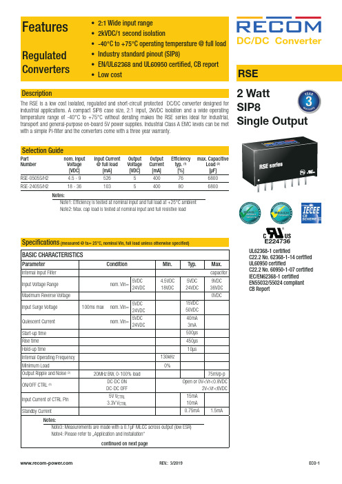
REV.: 3/2019ECO-1Regulated • 2:1 Wide input range • 2kVDC/1 Second isolation• -40°C To +75°C Operating temperature @ full load • Industry standard pinout (SIP8)• EN/UL62368 and UL60950 certified, CB report • Low cost RSEDescriptionThe RSE is a low cost isolated, regulated and short-circuit protected DC/DC converter designed forDC/DC Convert er2 WattE224736UL62368-1 certifiedC22.2 No. 62368-1-14 certfied UL60950 certifiedC22.2 No. 60950-1-07 certified IEC/EN62368-1 certified EN55032/55024 compliant CB ReportFeaturesConverters• 2:1 Wide input range • 2kVDC/1 second isolation -40°C to +75°C operating temperature @ full load • EN/UL62368 and UL60950 certified, CB report • Low costBASIC CHARACTERISTICSParameterCondition Min.Typ.Max.Internal Input Filter capacitor Input Voltage Range nom. Vin=5VDC 24VDC4.5VDC 18VDC5VDC 24VDC9VDC 36VDC Maximum Reverse Voltage 0VDCInput Surge Voltage 100ms max nom. Vin=5VDC 24VDC 15VDC 50VDC Quiescent Current nom. Vin=5VDC 24VDC40mA 3mA Start-up time 500µs Rise time 450µs Hold-up time10µsInternal Operating Frequency 130kHz Minimum Load0%Output Ripple and Noise (3)20MHz BW, 0-100% load75mVp-pON/OFF CTRL (4)DC-DC ON DC-DC OFF Open or 0V<Vr<0.8VDC2V<Vr<6VDC Input Current of CTRL Pin 5V V CTRL 3.3V V CTRL15mA 10mA Standby Current0.75mA1.5mAcontinued on next pageNotes:Note3: Measurements are made with a 0.1µF MLCC across output (low ESR) Note4: Please refer to …Application and Installation“Specifications (measured @ ta= 25°C, nominal Vin, full load unless otherwise specified)REV.: 3/2019ECO-2Specifications (measured @ Ta= 25°C, nominal Vin, full load unless otherwise specified)PROTECTIONSParameterTypeValueShort Circuit Protection (SCP)below 100m Wcontinuous, auto recoveryIsolation Voltage (5)I/P to O/Ptested for 1 second2kVDC Isolation Resistance 1G W min.Isolation Capacitance 100pF max.Insulation Gradefunctionalcontinued on next pageREGULATIONSParameterConditionValueOutput Accuracy 0-100% load ±2.0% max.Line Regulation low line to high line, full load±0.2% max.Load Regulation0% to 100% load±0.5% max.RSE-0505S/H2RSE-2405S/H2Accuracy vs. LoadA c c u r a c y [%]Output Current [A]000.20.10.30.40.50.60.10.20.30.4A c c u r a c y [%]Output Current [A]000.10.20.30.40.50.10.20.30.4REV.: 3/2019ECO-3Specifications (measured @ Ta= 25°C, nominal Vin, full load unless otherwise specified)ENVIRONMENTALParameterConditionValueOperating Temperature Range without derating (see graph)-40°C to +75°CMaximum Case Temperature +105°C Temperature Coefficient ±0.05%/°COperating Altitude 5000mOperating Humidity non-condensing5% - 95% RH max.Pollution Degree PD2MTBF according to MIL-HDBK-217F, G.B.+25°C +75°C2289 x 103 hours 781 x 103 hours VibrationMIL-STD 202G100806040200-4005075100150O u t p u t P o w e r [%]Ambient Temperature [°C]Derating Graph(@ Chamber and natural convection 0.1m/s)SAFETY AND CERTIFICATIONSCertificate Type (Safety)Report / File NumberStandard Information Technology Equipment, General Requirements for Safety E224736-A48UL60950-1, 2nd Edition, 2014CSA C22.2 No. 60950-1-07, 2nd Ed. 2014Audio/Video, information and communication technology equipment - Safety requirementsUL62368-1, 2nd Edition, 2014CSA C22.2 Nr. 62368-1-14, 2nd Ed. 2014Audio/Video, information and communication technology equipment - Safety requirements (CB Scheme)L0339m37-CB-1-B1IEC/EN62368-1, 2nd Edition, 2014RoHS 2+RoHS 2011/65/EU + AM2015/863continued on next pageSpecifications(measured @ Ta= 25°C, nominal Vin, full load unless otherwise specified)DIMENSION and PHYSICAL CHARACTERISTICSParameter Type ValueMaterialcasepottingPCBnon-conductive black plastic (UL94V-0)epoxy (UL94V-0)FR4 (UL94V-0)Dimension (LxWxH)21.8 x 9.2 x 11.1mm Weight 4.7g typ.continued on next pageC3 REV.: 3/2019ECO-4Specifications(measured @ Ta= 25°C, nominal Vin, full load unless otherwise specified)PACKAGING INFORMATIONPackaging Dimension (LxWxH)tube520.0 x 11.2 x 18.2mm Packaging Quantity22pcs Storage Temperature Range-55°C to +125°C Storage Humidity non-condensing5% - 95% RH max.The product information and specifications may be subject to changes even without prior written notice.The product has been designed for various applications; its suitability lies in the responsibility of each customer. The products are not authorized for use in safety-critical applications without RECOM’s explicit written consent. A safety-critical application is an application where a failure may reasonably be expected to endanger or cause loss of life, inflict bodily harm or damage property. The applicant shall indemnify and hold harmless RECOM, its affiliated companies and its representatives against any damage claims in connection with the unauthorizeduse of RECOM products in such safety-critical applications. REV.: 3/2019ECO-5。
迪电工业高速RS485隔离接收器模块说明书

single high speed RS485isolation transceiver module (with distribution)FEATURESl Two-terminal isolation (input and output are mutually isolated)l Integrated Isolated DC/DC converter l Bus protectionl Isolation voltage :2.5KVDCl Operating temperature range:-40℃~+105℃l Baud rate 115200bpsl Connect up to 32nodes on one bus l Isolation power output +5VTD311D485H/TD511D485H series are transceiver isolation module with integrated duplex power isolation,electrical isolation,and RS485interface bus protector ;Products can be easily embedded in the user equipment,achieve function of RS-485network connection.The isolation RS485circuits of using a piece of power isolation module,three light couplings and RS485transceivers and device are only need to adopt a RS485isolation module now.Simplify the customers on the isolation requirements of the design.1.Please read the technical manual carefully before use;contact our technical support if you have any problem.2.Do not use the product in hazardous areas.e DC power supply for the product and220V AC power supply is prohibited.4.Do not dismount and assemble the product without permission to avoid failure or malfunction of equipment.After-sales service1.Ex-factory inspection and quality control have been strictly conducted for the product;if there occurs abnormal operation or possibilityof failure of internal module,please contact the local representative or our technical support.2.The warranty period for the product is3years as calculated from the date of delivery.If any quality problem occurs under normal usewithin the warranty period,the product can be repaired or changed for free.Applied circuitSee Application Notes for Isolated Transmitter for details.Conventional CircuitNote:No pull up and pull-down resistor on A/B Line inside of the prodult,users connected according to the actaal situation① - New CircuitFig.12.Recommended EMC circuitRecommended external circuit parameters:Model TD311D485H /TD511D485H±0.25KV/±0.5KV±0.5KV/±1KV±1KV/±2KV±2KV/±4KV±4KV/±6KVC1220uF/10V(Electrolytic capacitor)220uF/10V(Electrolytic capacitor)TVS1SMCJ5.0A (TD311D485H)/SMCJ6.5A(TD511D485H)C2/C31uF/50V 1uF/50V L110μH 10μH C5/C6100pF/100V 100pF/100V C41nF/2KV 1nF/2KV R11M Ω1M ΩTVS2/TVS3/TVS4SMBJ15CA SMBJ15CA R4/R5----10Ω/2W(Wire-wound resistor)10Ω/2W(Wire-wound resistor)10Ω/2W(Wire -wound resistor)R2/R310Ω/1W(Wire-wound resistor)10Ω/2W(Wire-wound resistor)------GDT1/GDT2/GDT3----G30-A90XS30-A90XS50-A90XNotes:①GDT1,GDT2and GDT3be used instead of a three terminal gas discharge tube.Such as GDT1,GDT2and GDT3three two-terminal device available gas discharge tube instead of a three-terminal at "±4KV /±6KV"hierarchy,as B3D090L-C.②It is not needed the component when parameter with the symbol of "--".3.For more information please find the application notes on Notes:1.Packing Information please refer to 'Product Packing Information'.Packing bag number:58040012;2.Unless otherwise specified,data in this datasheet should be tested under the conditions of Ta=25℃,humidity<75%when inputting nominal voltage and outputting rated load;3.All index testing methods in this datasheet are based on our Company ’s corporate standards;4.The performance indexes of the product models listed in this datasheet are as above,but some indexes of non-standard model products will exceed the above-mentioned requirements,and please directly contact our technician for specific information;5.We can provide product customization service;6.Specifications of this product are subject to changes without prior notice.Mornsun Guangzhou Science &Technology Co.,Ltd.Address:No.5,Kehui St.1,Kehui Development Center,Science Ave.,Guangzhou Science City,Luogang District,Guangzhou,P.R.China Tel:86-20-38601850-8801Fax:86-20-38601272E-mail:***************。
南京优倍隔离器说明书

通用型隔离器性能简介:输入电流/电压信号,变送输出隔离的电流/电压信号,实现了输入、输出与电源之间的三端隔离;本产品响应快,功耗低,温度特性好。
应用范围:可与各类仪表及DCS,PLC等设备配套使用,在石油、化工、制造、电力、冶金等行业的重大工程中有着广泛应用。
技术参数:隔离传输准确度:±0.1%F·S(25℃±2℃)输出纹波:<1mV响应时间:≤0.2ms;可订制更快响应时间的产品稳定时间:≤2ms信号频率范围:0Hz~300Hz(0Hz~5kHz可订制)温度漂移:<30ppm/℃输入阻抗:电流:≤60Ω;电压:0V~5V:≥1MΩ;0V~10V:≥2MΩ负载能力:0mA~10mA:≤600Ω;; 0(4)mA~20mA:≤300Ω-10mA~+10mA:≤1kΩ; -20mA~+20mA:≤500Ω0(1)V~5V:≥1MΩ;0V~10V:≥2MΩ-5V~+5V:≥1MΩ; -10V~+10V:≥2MΩ需要更大的负载能力请在订货时说明。
功耗:单路输出两路输出24VDC 0.4W0.6W220VAC1.0V A 1.2V A供电电压范围:18V DC~32V DC85V AC~265V AC(120V DC~360V DC)面板说明:PWR:电源指示灯(绿色);工作时常亮。
通用型隔离器选型型号说明NPGL-CM ╳╳╳╳╳通用型隔离器缺省为单通道输入通道D双通道1 4mA~20mA2 1V~5V3 0mA~10mA3E -10mA~10mA4 0V~5V4E -5V~5V5 0V~10V5E -10V~10V6 0mA~20mA输入信号6E -20mA~20mA14mA~20mA21V~5V30mA~10mA3E-10mA~10mA40V~5V4E-5V~5V50V~10V5E-10V~10V60mA~20mA第一路输出6E-20mA~20mA缺省为无第二路输出1 4mA~20mA21V~5V3 0mA~10mA3E -10mA~10mA40V~5V4E -5V~5V50V~10V5E -10V~10V6 0mA~20mA第二路输出6E -20mA~20mA缺省为交流220V供电方式D 直流24V选型说明:正负信号输出的产品仅支持一入一出。
Velonex V-3050三相隔离器测试设备用户手册说明书

Maximum continuous current to load 25A RMS per phase, maximum intermittent loading of 30A per phase.
Maximum continuous DC current to load 20A.
When operating loads close to the above specified current limits, a voltage drop of less then 10% can be expected at the load. An additional 7.5A of capacitive current per phase will be required when operating at 277VRMS per phase with proportionally less at lower vol tages.
AC Line Voltage:
\1aximul1l line voltage to load. lSOV R\TS, SO/60Hz phase to phase and 277V per phase to neutral (Y only). LIp to 250V /\. Up to 277v per single phase.
The r\-10del V-30S0 Surge Coupler/Isolation l!nit employes an active dIgital interlock system for operator protection. L.E.D. annunciators tell the status of any interlock. If an interlock opens, the automatic shut-down of the surge and three-phase power follows. High voltage shielded cables are used to couple surge ~ignab b~l\\een ~ystem units ror o[J~rator ~dfety. Circuit breaker protection is employed for all three-phase power to the E. U.T.
摩恩孙高速RS485隔离传输器模块(增强版)说明书

Single high speed RS485isolation transceiver module(enhanced version)CBRoHSFEATURES●Baud rate high up to 500Kbps●The bus is able to support 256nodes at maximum ●2500VDC isolation voltage (input and output)●Integrated high efficiency isolated DC/DC converter●Operating temperature range:-40℃to +85℃●ESD protection (IEC/EN61000-4-2Contact ±4KV perf.Criteria B)●IEC60950,UL60950,EN60950approvalPART NUMBER SYSTEMTD501D485H-ESpecial mark RatePort signal type Package type Channel numberPower distrubution output Power inputDigital bus interface product typeSingle high rate RS485isolation transceiver module TD301D485H-E/TD501D485H-E series are RS485transceiver module with integrated isolated power,Signal isolated chip and the bus protection device.Product's main function is to convert logic level to difference level of the RS485agreement,and it implements the function of signal isolation.Products is with isolation power.It can achieve 2500VDC electrical isolation and have the function of ESD protection.Product can be easily embedded user equipment,makes the equipment easily implement connection of RS485protocol network .Selection GuideCertification Part No.Power Supply input (VDC)UL/CE/CBTD301D485H-E 3.17-3.45TD501D485H-E4.75-5.25Input SpecificationsItemOperating ConditionsValue Power SupplyStatic current Products energized,no communication ≤40mA Send current 200kbps Square wave communication≤70mAInput PortSerial interface TD301D485H-E compatible with +3.3V UART interface TD501D485H-E compatible with +5V UART interfacePin currentI TXD ≤2mA;I RXD ≤2mA;I CON ≤5mABus InterfaceItem Operating ConditionsValueOutput PortRS485bus interfaceStandard interface RS485,pull-up and pull-downresistor,whose value is 5.1K,have been set to A/B line.Transmission SpecificationsItem Operating ConditionsValueData Rate500Kbps (max.)Transceiver Switching Delay ≤30usThe Number of Nodes Connect up to 256nodes on one busTransceiver controlContrary to common RS485transceiver control levelTruth TableSending StatusControlInput Output CON TXD A B Line state 0110Normal 01NormalTruth Table Receiving Status Control Input Output CON A-B RXD 1≥0.2V11≤-0.2V0General SpecificationsItem Operating Conditions ValueElectric Isolation Two-terminal isolation(input and output are mutually isolated) Isolation Voltage Testing for1minute,leakage current<5mA,humidity<95%2.5KVDCOperating Temperature-40℃to+85℃Transportation and StorageTemperature-50℃to+105℃Operating Humidity10%-90%Max.Casing Temperature Ta=25℃≤50℃Application Environment The presence of dust,fierce vibration,impulsion and corrosive gas may cause damage to the productSafety Standard IEC60950/EN60950/UL60950 Safety Certification IEC60950/EN60950/UL60950 Safety Class CLASS IIIPhysical SpecificationsCasing Material Black flame-retardant heat-proof epoxy resinPackage DIP10Weight4g(Typ.)Cooling Method Free air convectionEMC SpecificationsEMI CE CISPR22/EN55022CLASS A(see2-②for recommended circuit) RE CISPR22/EN55022CLASS A(see2-②for recommended circuit)EMS ESD IEC/EN61000-4-2Contact±4KV perf.Criteria B EFTIEC/EN61000-4-4Power supply port±2KV(see2-①for recommended circuit)perf.Criteria B IEC/EN61000-4-4Signal port±1KV(see2-③for recommended circuit)perf.Criteria BSurge IEC/EN61000-4-5Power supply port±1KV(line to line)(see2-①for recommended circuit)perf.Criteria BSignal port±0.25KV(line to line)/±0.5KV(line to ground)(see2-③for recommended circuit)perf.Criteria B Signal port±0.5KV(line to line)/±1KV(line to ground)(see2-③for recommended circuit)perf.Criteria B Signal port±1KV(line to line)/±2KV(line to ground)(see2-③for recommended circuit)perf.Criteria B Signal port±2KV(line to line)/±4KV(line to ground)(see2-③for recommended circuit)perf.Criteria B Signal port±4KV(line to line)/±6KV(line to ground)(see2-③for recommended circuit)perf.Criteria BApplication Precautions1.Please read the technical manual carefully before use;contact our technical support if you have any problem.2.Do not use the product in hazardous areas.e DC power supply for the product and220V AC power supply is prohibited.4.Do not dismount and assemble the product without permission to avoid failure or malfunction of equipment.After-sales service1.Ex-factory inspection and quality control have been strictly conducted for the product;if there occurs abnormal operation or possibilityof failure of internal module,please contact the local representative or our technical support.2.The warranty period for the product is3years as calculated from the date of delivery.If any quality problem occurs under normal usewithin the warranty period,the product can be repaired or changed for free.Applied circuitSee Application Notes for Isolated Transmitter for details.Design Reference1.Typical application circuit0.1UFDC/DCVCC TXDCONRXD MCUDIDE RE ROSP3085EENGNDA B VCC+5V6N1376N1376N137+5VConventional CircuitRXD TXD GND VCC A B RGND1098RXD TXD 1234MCUVCC485 BusCONCON5New CircuitFig.12.EMC solution-recommended circuitGND +TXD L1RXD CONRGN DA B123451098TVS1C1C2C3①②R4TVS2R5TVS3TVS4GDT1R1C4③VCC C5C6A1B1R2R3GDT2GDT3④Fig.2Recommended external circuit parameters:Model TD301D485H-E /TD501D485H-E±0.25KV/±0.5KV±0.5KV/±1KV±1KV/±2KV±2KV/±4KV±4KV/±6KVC1220uF/10V(Electrolytic capacitor)220uF/10V(Electrolytic capacitor)TVS1SMCJ5.0A (TD301D485H-E)/SMCJ6.5A(TD501D485H-E)C2/C31uF/50V 1uF/50V L110μH 10μH C5/C6100pF/100V 100pF/100V C41nF/2KV 1nF/2KV R11M Ω1M ΩTVS2/TVS3/TVS4SMBJ15CA SMBJ15CA R4/R5----10Ω/2W(Wire-wound resistor)10Ω/2W(Wire-wound resistor)10Ω/2W(Wire-wound resistor)R2/R310Ω/1W(Wire-wound resistor)10Ω/2W(Wire-wound resistor)------GDT1/GDT2/GDT3----G30-A90XS30-A90XS50-A90XNotes:1.GDT1,GDT2and GDT3be used instead of a three terminal gas discharge tubey.Such as GDT1,GDT2and GDT3three two-terminal device available gas discharge tube instead of a three-terminal at "±4KV /±6KV"hierarchy,as B3D090L-C.2.It is not needed the component when parameter with the symbol of "--".3.For more information please find the application notes on Dimensions and Recommended Layout∅0.50 [0.020]4.10 [0.161]17.00 [0.669]15.24[0.600]10.16 [0.400]20.00 [0.787]48TD_D485H Receiving Pin TD_D485H BPin RXDB910TD_D485H APin Isolation Power Output RGND ARGND1Input Power VCC2GND GND3TD_D485H Send PinTXD 5Send&Receiving Control Pin CON412358910384125910∅1.00 [∅0.039]Pin-OutPin FunctionBottom ViewFront ViewNote:Unit :mm[inch]Pin diameter tolerances :±0.10[±0.004]General tolerances:±0.25[±0.010]Designation Note: Grid 2.54*2.54mm1104003202-B0THIRD ANGLE PROJECTION7.00 [0.276]2.54 [0.100]Notes:1.Packing Information please refer to 'Product Packing Information'.Packing bag number:58040012;2.Unless otherwise specified,data in this datasheet should be tested under the conditions of Ta=25℃,humidity<75%when inputting nominal voltage and outputting rated load;3.All index testing methods in this datasheet are based on our Company’s corporate standards;4.The performance indexes of the product models listed in this datasheet are as above,but some indexes of non-standard model products will exceed the above-mentioned requirements,and please directly contact our technician for specific information;5.We can provide product customization service;6.Specifications of this product are subject to changes without prior notice.Mornsun Guangzhou Science &Technology Co.,Ltd.Address:No.5,Kehui St.1,Kehui Development Center,Science Ave.,Guangzhou Science City,Luogang District,Guangzhou,P .R.China Tel:86-20-38601850-8801Fax:86-20-38601272E-mail:***************。
MORNSUN TR1x0PWE 热阻隔离器说明书
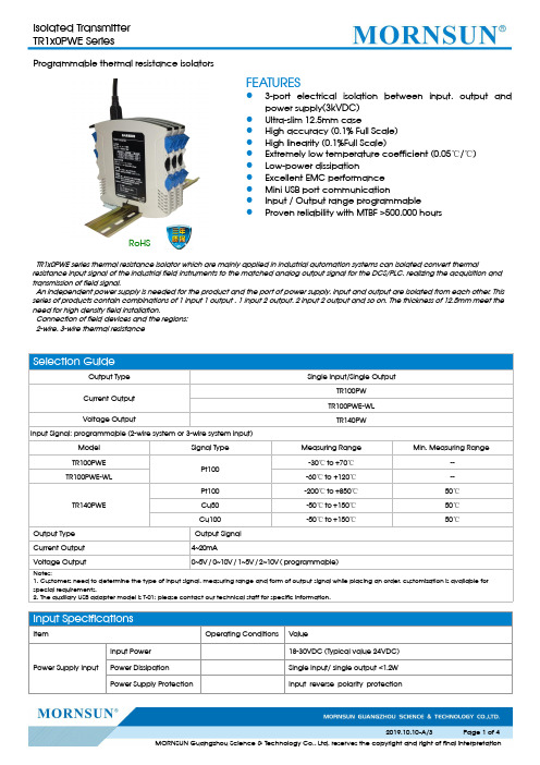
Programmable thermal resistance isolatorsRoHSFEATURES●3-port electrical isolation between input,output and power supply (3kVDC)●Ultra-slim 12.5mm case●High accuracy (0.1%Full Scale)●High linearity (0.1%Full Scale)●Extremely low temperature coefficient (0.05℃/℃)●Low-power dissipation●Excellent EMC performance ●Mini USB port communication●Input /Output range programmable●Proven reliability with MTBF >500,000hoursTR1x0PWE series thermal resistance isolator which are mainly applied in industrial automation systems can isolated convert thermalresistance input signal of the industrial field instruments to the matched analog output signal for the DCS/PLC,realizing the acquisition and transmission of field signal.An independent power supply is needed for the product and the port of power supply,input and output are isolated from each other.This series of products contain combinations of 1input 1output ,1input 2output,2input 2output and so on.The thickness of 12.5mm meet the need for high density field installation.Connection of field devices and the regions:2-wire,3-wire thermal resistanceField Area Input Signal See List of Product ModelsGB/T24338.4-2009signal port ±2KV (line-to-ground)perf.Criteria B CSGB/T24338.4-200910Vr.m.sperf.Criteria A2.Do not use the product in hazardous areas;e only DC power supply source for this product and 220V AC power supply is prohibited;4.It is strictly forbidden to disassemble the product privately in order to avoid product failure or malfunction.Bottom power supply port111291078123456P o w e r P o w e r -P o w e r P o w e r -Note: When us e bottom power supply, anyone group or both is OK.PIN Description (double input double output)1NC2NC 3NC4L1C Signal 1input line C 5L1B Signal 1input line B 6L1A Signal 1input line A 7So1-Signal 1output-8So1+Signal 1output+9NC 10NC11Power-power input-12Power+power input+TR1x0PWE SeriesFie ld Area18~30V DC 2-wire system Input out putO utp utVol ta ge so urce out put①Use dismountable terminals for instrument wiring,easy to operate;②The sectional area of conductor is 0.5mm 2-2.5mm 2;③The length of conductor exposed is 8mm and is fastened by M3bolts.2.For additional information please refer to application notes on Installation &RemovalInstallationStandard 35mm DINrail installation:1.Insert top of Module into DIN rail;2.Push bottom of Module into rail until it snaps in.Removal1.Insert screw driver on the lower end of Module to release clamp(tool edge width ≤6mm);2.Push screw driver up towards Module to slide clamp out;3.Pull Module up out of the guide rail.Notes:1.For additional information on Product Packaging please refer to .The Packaging bag number:58240007;2.Unless otherwise specified,parameters in this datasheet were measured under the conditions of Ta=25℃,humidity<75%RH with nominal input voltage and rated output load;3.All index testing methods in this datasheet are based on company corporate standards;4.The above are the performance indicators of the product models listed in this datasheet.Some indicators of non-standard models will exceed the above requirements.For details,please contact our technical staff;5.We can provide product customization service,please contact our technicians directly for specific information;6.Products are related to laws and regulations:see "Features"and "EMC";7.Our products shall be classified according to ISO14001and related environmental laws and regulations,and shall be handled by qualified unitsMORNSUN Guangzhou Science &Technology Co.,Ltd.Address:No.5,Kehui St.1,Kehui Development Center,Science Ave.,Guangzhou Science City,Huangpu District,Guangzhou,P.R.China Tel:86-20-38601850Fax:86-20-38601272E-mail:***************。
Recom-Power Rxx-B系列高输出电压隔离DC DC转换器说明书

Rxx-BDescriptionThe Rxx-B series are 5W regulated high output voltage isolated DC/DC converters in a DIP24 pack-age. Three adjustable output voltages of 87V (41-120V), 103V (50-135V) or 159V (92-200V) are of-fered, with nominal input voltage options of 5V, 12V, 15V or 24V. The modules can be cascaded for higher output voltages up to 400VDC. The output is isolated from the input with 3kVDC isolation and the modules can be operated over a -40°C to +85°C ambient temperature range. The Rxx-B series is safety certified with IEC/EN60950-1 certifications (the R24-100B has additionally UL/IEC/EN62368 with CB Report). A three year warranty is offered.DC/DC Convert er5 Watt DIP24Single OutputEN60950-1 certifiedIEC60950-1 certifiedSelection GuidePart Input nom. Output Output Output Efficiency Max. CapacitiveNumber Voltage Range Voltage Voltage Range Power max. (1)typ. (2) Load (3) [VDC] [VDC] [VDC] [W] [%] [µF]R05-100B 4.5 - 6 87 +41...+120 3 77 20R12-100B 10 - 14 103 +50...+135 5 82 30R15-100B 14 - 17 103 +59...+130 5 82 30R24-100B 21 - 27 105 +56...+135 5 84 30R12-150B10 - 14 159 +92...+200 5 82 40R15-150B 14 - 17 159 +92...+200 5 82 40R24-150B 21 - 27 159 +92...+200 5 84 40Notes:Note1: Refer to …Power Limit“ graphNote2: Efficiency is tested at nominal input and full load at +25°C ambient Note3: Max. Cap Load is tested at nominal input and full resistive load. If the load is mainly capacitive, it should have a minimum resistive load of 10mAModel Numberingnom. Input VoltageOutput VoltageR - BSpecifications (measured @ Ta= 25°C, nom. Vin and full load)PROTECTIONSParameterConditionValueShort Circuit Protection (SCP)continuous, automatic restartIsolation Voltage tested for 1 second3kVDC min.Isolation Resistance 1G Ω min.REGULATIONSParameterCondition ValueOutput Accuracy ±5.0% max.Line Regulation low line to high line ±0.5% max.Load Regulation20% to 100% load0.5% max.Specifications (measured @ Ta= 25°C, nom. Vin and full load)SAFETY AND CERTIFICATIONSCertificate Type (Safety)Report / File NumberStandard Information Technology Equipment, General Requirements for Safety SPCLVD1605077-02IEC60950-1:2005, 2nd Edition + AM 2:2013EN60950-1:2006 + AM 2:2013EAC RU-AT.49.09571TP TC 004/2011RoHS2RoHS-2001/65/EU + AM-2015/863ENVIRONMENTALParameterConditionValueOperating Temperature Range with derating @ free air convection (see graph)full load @ free air convection (see graph)-40°C to +85°C -40°C to +70°C Temperature Coefficient ± 0.02%/°COperating Altitude 2000m Operating Humidity non-condensing95% RH max.Pollution Degree PD2MTBFaccording to MIL-HDBK-217F, G.B.+25°C1400 x 103 hours-40-2002040708560-30-101030508090100100806040907050302010O u t p u t L o a d [%]Ambient Temperature [°C]Derating Graph(@ free air convection)DIMENSION AND PHYSICAL CHARACTERISTICSParameterTypeValueMaterialcase potting PCBnon conductive black plastic, (UL94 V-0)epoxy, (UL94 V-0) FR4, (UL94 V-0)Package Dimension (LxWxH)31.2 x 20.3 x 9.4mmPackage Weight12g typ.Specifications (measured @ Ta= 25°C, nom. Vin and full load)Specifications (measured @ Ta= 25°C, nom. Vin and full load)PACKAGING INFORMATIONParameter Type Value Packaging Dimension (LxWxH)tube 530.0 x 23.0 x 19.0mm Packaging Quantity tube 6pcs Storage Temperature Range- 50°C to +125°C Storage Humidity95% RH max.The product information and specifications may be subject to changes even without prior written notice.The product has been designed for various applications; its suitability lies in the responsibility of each customer. The products are not authorized for use in safety-critical applications without RECOM’s explicit written consent. A safety-critical application is an application where a failure may reasonably be expected to endanger or cause。
通用型智能隔离器说明书
16 + (L)
单路电流输入-单输出
-1
V
+2
9+
输出
10 -
14 接地
15 -(N)
电源
16 + (L)
单路电压输入-单输出
-1
mA
+2
9+
10
输出1
-
-1
电压输入
11 +
+2
12
输出2
-
14 接地
15 - (N)
16
电源
+ (L)
9+
10
输出1
-
11 +
12
输出2
-
14 接地
15 -(N)
16
ANPE 优倍电气 America New Power Electric
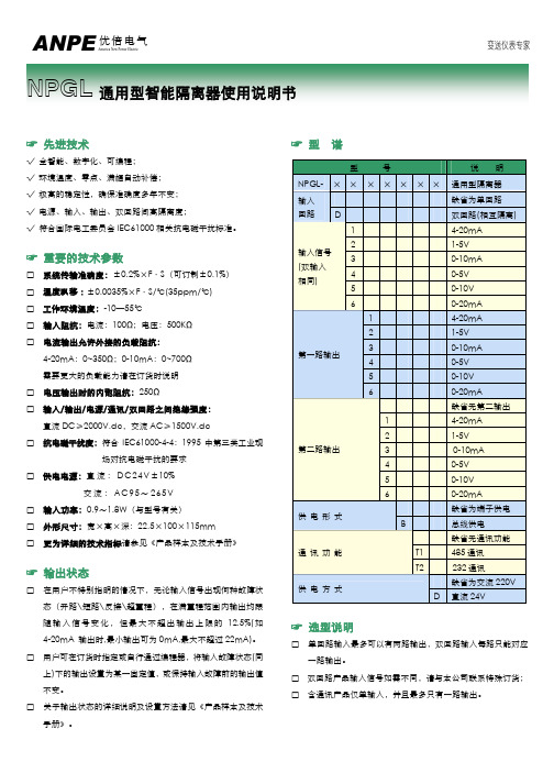
NPGL 通用型智能隔离器使用说明书
变送仪表专家
☞ 先进技术
√ 全智能、数字化、可编程; √ 环境温度、零点、满幅自动补偿; √ 极高的稳定性,确保准确度多年不变; √ 电源、输入、输出、双回路间高隔离度; √ 符合国际电工委员会 IEC61000 相关抗电磁干扰标准。
☞ 选型说明
□ 单回路输入最多可以有两路输出,双回路输入每路只能对应 一路输出。
□ 双回路产品输入信号如需不同,请与本公司联系特殊订货; □ 含通讯产品仅单输入,并且最多只有一路输出。
ANPE 优倍电气 America New Power Electric
变送仪表专家
☞ 面板指示
□ PWR:电源指示灯(绿色); □ ALM:输入信号报警指示灯(红色);
☞ 使用环境
安装位置不得有强烈振动,以及来自信号端、电源端及空间 的超过 IEC61000-4-4:1995 中第三类工业现场电磁干扰的强度, 并使用环境中不得有对金属、塑料件起严重腐蚀作用的有害物质。
Radial Twin-Iso双通道线级隔离器说明书

Radial Engineering Ltd.1845 Kingsway Ave., Port Coquitlam, BC V3C 1S9, Canada Tel: 604-942-1001 • Fax: 604-942-1010 email:******************Twin-Iso ™True to the Music Radial Twin-Iso user guide - Part #: R870 1025 00 / 10-2021User Guide ®WELCOMECongratulations on your purchase of the Radial Twin-Iso stereo (dual mono) line-level isolator. The Twin-Iso is a handy device that will allow you to isolate audio equipment and eliminate troublesome noise caused by ground loops.The Radial Twin-Iso employs two high-performance Jensen isolation transformers to ensure the best signal transfer is enjoyed without artifacts or distortion. This makes the Twin-Iso a perfect choice where multiple consoles need to be sub-mixed, when isolating amplifi er distribution racks and for connecting remote speaker towers. The Twin-Iso can also eliminate ground loop problems where equipment must be connected to alternate power sources such as generators.As with all Radial products, the Twin-Iso is made with 14 gauge steel and features an internal welded I-beam frame for maximum rigidity. Switches and jacks are protected by our unique bookend construction, making the Twin-Iso virtually impossible to damage even in the most abusive touring environments.We have purposely written this manual to be short, as most users will likely be familiar with the Twin-Iso’s applications. We do suggest that you take a moment to read through this document to familiarize yourself with the features that have been built in. For more detailed information, please visit the Radial website. This is where we post questions and answers that come from users after the product is released. If you do not fi nd an answer, we invite you to send *********************************************************** query in a prompt and professional manner.The Radial Twin-Iso is a wonderful device that will surely provide you with years of problem-solving connectivity. Enjoy!INTRODUCTIONThe Radial Twin-Iso has been designed to provide electrical isolation between two line-level devices such as between two mixing consoles, remote speakers, crossovers and amplifi er racks. Use the Twin-Iso anywhere source and destination devices may cause system noise because of diff erent ground potentials (often referred to as ground loops).So-called ground loops are caused by diff ering voltage references from various pieces of equipment that, when connected together, can introduce a 60 cycle hum in the sound system. Although there are various solutions that can beengineered to eliminate noise, the simplest and most eff ective is to isolate the source and destination with an audio transformer.The Radial Twin-Iso employs two high-quality Jensen transformers to do the task. Jensen is renowned for their quality and the ability of their transformers to handle high signal levels without saturation and transfer the signal without introducing phase distortion or group delay. Although the cost is higher, a good quality transformer will assure the signal remains true to the source, resulting in better sound.When you fi rst pick up the Radial Twin-Iso, you will immediately notice the weight. This ‘hefty’ device employs a welded steel I-beam internal construction to assure the internal PCB will not torque, preventing part failure. Besides the heavy-duty enclosure, the extra-large transformers add to the Twin-Iso’srobustness. As a rule, the larger the transformer, the more signal handling capacity it will have and Jensen transformers can drive loads of 600 ohms up to +21dBu at 20Hz.The Radial Twin-Iso is equipped with two XLR inputs and two XLR outputs. Each channel is 100% isolated from the other to eliminate cross-talk or interaction, thus allowing two completely diff erent audio sources to use the Twin-Iso at the same time. Although the Twin-Iso is designed for +4dB professional line-level signals, the transformers will actually handle over 20dB without choking.Each of the Twin-Iso’s outputs feature a 180° polarity reverse switch to ensure both consoles are ‘in phase’ and pushing the speakers in the same direction. This allows the Twin-Iso to feed a sub-group or auxiliary input of a console where polarity reversals are generally not provided. Finally, the Twin-Iso is equipped with a ground lift switch to further reduce system noise should it be present.USING THE TWIN-ISOAs with all Radial products, using the Twin-Iso is simple and straight forward. Make sure the sound system is turned off and all levels are set to zero before making audio connections. This will avoid any pops in the sound system that could cause damage to speakers.The Twin-Iso is completely passive and does not require a power supply of any kind. Connect the source device to the Twin-Iso inputs. Connect the Twin-Iso outputs to the destination device. Turn the system up slowly and listen for noise. In the unlikely event you should encounter noise, simply depress the ground lift switch. That’s all there is to it.AUX CONSOLE master outputs connect to Twin-Iso inputs.MAIN CONSOLE Twin-Iso outputs feed main console.J-RAK The optional J-RAK™ is a high density rackshelf for Radial DI’s and splitters.It’s a 2RU rack chassis that allows up to 8 Radial devices in one neat high density 19" package. The DI’s can be mounted with either the input side or output side facing the front. Ideal for studio or touring. Constructed of 14 gauge steel with a baked enamel fi nish.J-CLAMP The optional J-CLAMP™ can mount a single Radialdevice to virtually any surface. Perfect for hiding awayinside racks, on podiums or under tables. Constructedof 14-gauge steel with a baked enamel fi nish.TWIN-ISO BLOCK DIAGRAM LEFT IN LEFT OUT RIGHT IN RIGHT OUT POLARITY GND LIFTPOLARITY98INPUT PANEL1. Ground lift (inputs) Lifts the ground pin-1 on bothXLR input connectors. 2. Input-1 & 2 For low impedance, balanced line-level signals.3. Bookend design 14gauge steel outer shellcreates protective zone around connectors andswitches. OUTPUT PANEL4. Output-1 & 2 line-level transformer-isolatedoutputs.5. Polarity reverse 180°- Polarity reverse switch foroutputs-1 & 2.6. Full-bottom no-slip pad This provides electricalisolation and plenty of"stay-put" friction to keepthe Twin-ISO in one place.CONSTRUCTION7. Ultra rigid steel I-beam enclosure eliminatesstress that could torquethe PC board and causesolder joint failure.8. Jensen transformers off er outstanding audioperformance.9. Military-grade double-sided PCB with plated through-holes is bolted towelded steel standoff s.10. Sturdy high-cycle PCB mounted switches arerated for long life.731056TWIN-ISO SPECIFICATIONSFrequency response 10Hz to 50kHz +/- 1dBMax output level +21dBu (20Hz, 1% THD)Phase distortion 0.3° at 20HzTotal harmonic distortion 0.001% THD @1k, +4dBu (0.035% at 20Hz) Common-mode rejection 94dB @ 60Hz (83dB @ 3kHz)Inputs Balanced, line-level, pin-2 hotOutputs Balanced, line-level, pin-2 hotPower requirement None, completely passiveSize 3.25" x 5" x 1.875"Weight2 lbs.RADIAL LIMITED THREE YEARTRANSFERABLE WARRANTYRADIAL ENGINEERING LTD. (“Radial”) warrants this product to be free from defects in material and workmanship and will remedy any such defects freeof charge according to the terms of this warranty. Radial will repair or replace (at its option) any defective component(s) of this product (excluding fi nish and wear and tear on components under normal use) for a period of three (3) years from the original date of purchase. In the event that a particular product is no longer available, Radial reserves the right to replace the product with a similar product of equal or greater value. To make a request or claim under this limited warranty, the product must be returned prepaid in the original shipping container (or equivalent) to Radial or to an authorized Radial repair center and you must assume the risk of loss or damage. A copy of the original invoice showing dateof purchase and the dealer name must accompany any request for work to be performed under this limited and transferable warranty. This limited warranty shall not apply if the product has been damaged due to abuse, misuse,misapplication, accident or as a result of service or modifi cation by any other than an authorized Radial repair center.THERE ARE NO EXPRESSED WARRANTIES OTHER THAN THOSE ON THE FACE HEREOF AND DESCRIBED ABOVE. NO WARRANTIES WHETHER EXPRESSED OR IMPLIED, INCLUDING BUT NOT LIMITED TO, ANY IMPLIED WARRANTIES OF MERCHANTABILITY OR FITNESS FOR A PARTICULAR PURPOSE SHALL EXTEND BEYOND THE RESPECTIVE WARRANTY PERIOD DESCRIBED ABOVE OF THREE YEARS. RADIAL SHALL NOT BE RESPONSIBLE OR LIABLE FOR ANY SPECIAL, INCIDENTAL OR CONSEQUENTIAL DAMAGES OR LOSS ARISING FROM THE USE OF THIS PRODUCT. THIS WARRANTY GIVES YOU SPECIFIC LEGAL RIGHTS, AND YOU MAY ALSO HAVE OTHER RIGHTS, WHICH MAY VARY DEPENDING ON WHERE YOU LIVE AND WHERE THE PRODUCT WAS PURCHASED.True to the Music ®。
- 1、下载文档前请自行甄别文档内容的完整性,平台不提供额外的编辑、内容补充、找答案等附加服务。
- 2、"仅部分预览"的文档,不可在线预览部分如存在完整性等问题,可反馈申请退款(可完整预览的文档不适用该条件!)。
- 3、如文档侵犯您的权益,请联系客服反馈,我们会尽快为您处理(人工客服工作时间:9:00-18:30)。
newpwr隔离器说明书
NewPWR隔离器说明书
第一章:产品概述
NewPWR隔离器是一种用于电力系统中的安全保护设备。
它的作用是在两个电力系统之间提供有效的隔离,以防止电流和电压的传导。
NewPWR隔离器具有高绝缘性能,可有效地隔离电力系统,保护设备和人员的安全。
第二章:产品特点
1. 高绝缘性能:NewPWR隔离器采用优质的绝缘材料制造,能够承受高电压和高电流,确保电力系统的安全运行。
2. 可靠性高:NewPWR隔离器具有优异的可靠性,能够在恶劣的环境条件下正常工作,保持长时间的稳定运行。
3. 安全性强:NewPWR隔离器能够有效地隔离电力系统,防止电流和电压的传导,保护设备和人员的安全。
4. 使用方便:NewPWR隔离器采用简单的操作方式,用户可以轻松地进行安装和维护。
第三章:产品应用
NewPWR隔离器广泛应用于以下领域:
1. 电力系统:NewPWR隔离器可用于电力系统中的高压设备隔离,确保设备运行的安全性。
2. 工业控制:NewPWR隔离器可用于工业控制系统中的信号隔离,防止干扰和故障。
3. 通信系统:NewPWR隔离器可用于通信系统中的信号隔离,提高通信质量和稳定性。
4. 医疗设备:NewPWR隔离器可用于医疗设备中的电路隔离,确保医疗设备的安全性和可靠性。
第四章:产品安装与维护
1. 安装:在安装NewPWR隔离器时,首先要确保设备与电力系统的连接正确无误。
然后,按照说明书中的步骤进行安装,并进行必要的调试和测试。
2. 维护:定期对NewPWR隔离器进行维护,包括清洁、检查和测试。
如果发现故障或异常情况,应及时采取措施进行修复或更换。
第五章:注意事项
1. 在安装和维护NewPWR隔离器时,务必遵守安全操作规程,确保人员和设备的安全。
2. 在使用NewPWR隔离器时,应遵循产品说明书中的使用规范,避免超过额定电流和电压的范围。
3. 如需更换NewPWR隔离器的零部件或进行维修,请联系专业人员进行操作,切勿私自拆卸或修理。
第六章:常见问题解答
1. 问:NewPWR隔离器适用于哪些电力系统?
答:NewPWR隔离器适用于各种电力系统,包括高压、低压和中压系统。
2. 问:NewPWR隔离器的绝缘性能如何?
答:NewPWR隔离器具有优异的绝缘性能,能够承受高电压和高电流,确保电力系统的安全运行。
3. 问:如何安装NewPWR隔离器?
答:安装NewPWR隔离器时,需要确保设备与电力系统的连接正确无误,并按照说明书中的步骤进行安装和调试。
4. 问:如何进行NewPWR隔离器的维护?
答:定期对NewPWR隔离器进行清洁、检查和测试,并在发现故障或异常情况时及时采取修复或更换措施。
第七章:总结
NewPWR隔离器是一种用于电力系统中的安全保护设备,具有高绝缘性能和可靠性高的特点。
它广泛应用于电力系统、工业控制、通信系统和医疗设备等领域。
在安装和维护NewPWR隔离器时,需要遵守安全操作规程,确保人员和设备的安全。
如有任何问题或需要更多信息,请随时联系我们的专业人员。