XL1410降压型直流电源变换器芯片(高效率型)
xl1509中文资料

xl1509中文资料Prediminarydatasheet 2A 150kHz 40V Buck DC DCconverter xl1509 Rev 2.0 Xinlong Semiconductor Limited Corporation宽输入电压范围4.5v-40v内置频率补偿,热关断功能,限流功能,短路保护功能可选包装形式:sop-8应用领域:通信/网络设备概述xl1509是一个150kHz固定频率脉冲宽度调制(降压)DC / DC转换器。
它具有2A负载驱动能力,高效率,低纹波和出色的线性度。
它具有良好的负载调节能力,并且只需要最少的外部组件。
可调输出,易于使用,内置频率补偿和固定频率振荡器。
PWM控制电路可将占空比从0调整到100%。
具有启用功能和内置的过电流和短路保护功能,在进行过电流和短路保护的情况下,xl1509的工作频率将从150kHz降低到50KHz。
内置频率补偿模块使xl1509的外部组件最大化。
图1xl1509封装类型的初步数据表2A 150kHz 40V Buck DC DC转换器xl1509 Rev 2.0新龙半导体有限公司xl1509的引脚结构(顶视图)表1引脚说明引脚编号引脚名称引脚名称VIN电压输入引脚xl1509在4.5V 40V 直流电压下工作,输入外部连接适用于大的接地旁路电容,以消除输入噪声。
SW电源开关输出引脚(SW)。
输出是提供功率输出的开关节点。
GND接地引脚必须精心设计。
该引脚必须放置在硝基基极二极管的外部,并且输出电容器接地,以防止由感应电压引起的开关电流毛刺输入到xl1509。
FB的反馈引脚(FB),通过外部电阻来分割环路,反馈是检测并调节输出电压,反馈端电压为1.23V。
开/关使能引脚。
如果驱动器的开/关引脚为低电平,则设备将被打开;否则,设备将被打开。
否则,设备将打开。
如果引脚为高电平,则设备将关闭。
初步数据表2A 150kHz 40V Buck DC转换器xl1509 Rev 2.0鑫隆半导体有限公司xl1509功能框图典型应用电路图4. Xl1509典型应用电路12v-5v / 2A初步数据表2A 150kHz 40V Buck DC DC转换器xl1509 Rev 2.0鑫隆半导体有限订购信息部件号标记标记标记温度范围封装类型xl1509-adje1 xl1509-adje1 3.3exl1509-3.3e1xl1509-3.3e1xl1509-3.3e1xl1509-3.3e1xl1509-3.3ee1xl1509-5.0e1xl1509-5.0e1xl 1509-5.01 e1xl1x1x1-3.3ttree1 xl1509-3.3tree1 xl1509-3.3tree1 xl1509-3.3tree1 xl1509-3.0 tree1 xl1509-5.0 tree1 xl1509-5.0 tree1 xl1509-5.0-5-5.0e1xl1509-5-5-5-5.0e1xl1509-5-5.0e1 xl1509-5-5-5.0e1 xl1509-5-5-5.0-exl1509-3.3e1e1xl1509-3.3e1 xl1509-3.3e1 xl1509-3.3e1 xl1509-5.3ee1xl1509-5.3e1-eee e5.3e40 xl13“E1”后缀符合ROHS标准初步数据表2A 150kHz 40V Buck DC DCconverter xl1509 Rev 2.0 Xinlong Semiconductor Limited Corporation maximum rati ng(注1)参数符号单位输入电压vin-0.3 fb-0.3开/关引脚电压开/关0.3输出-0.3内部极限MW(soic8)(结环境,未加热,自然通风)JA100 stg-的电阻焊接温度65引线(PIN)(热焊接,10引线260 ESD(人体模型)2000注1:超过所列的最大额定值将对设备造成永久性损坏。
中压降压恒压芯片(高效率)XL1410
中压降压恒压芯片(高效率)XL1410应用领域:便携式电子设备、智能家居、电子门禁系统、音响功放、小家电控制板、车载电子设备等。
描述221019A02 是为产品 XL1410 制作的演示板,用于 DC8V~18V 输入,输出电压 5V,最大输出电流 1A 的降压应用,最高转换效率可以达到 90%。
XL1410 是开关降压型 DC-DC 转换芯片;固定开关频率 380KHz,可减小外部元器件尺寸,方便 EMC 设计。
芯片具有出色的线性调整率与负载调整率,芯片内部集成过流保护、过温保护、短路保护等可靠性模块。
XL1410 为标准 SOP8 封装,集成度高,外围器件少,应用灵活。
应用信息输入电容选择在连续模式中,转换器的输入电流是一组占空比约为VOUT/VIN 的方波。
为了防止大的瞬态电压,必须采用针对最大RMS 电流要求而选择低ESR(等效串联电阻)输入电容器。
对于大多数的应用,1 个4.7uF 的输入电容器就足够了,它的放置位置尽可能靠近 XL1410 的位置上。
输出电容选择在输出端应选择低ESR 电容以减小输出纹波电压,一般来说,一旦电容 ESR 得到满足,电容就足以满足需求。
任何电容器的 ESR 连同其自身容量将为系统产生一个零点,ESR 值越大,零点位于的频率段越低,而陶瓷电容的零点处于一个较高的频率上,通常可以忽略,是一种上佳的选择,但与电解电容相比,大容量、高耐压陶瓷电容会体积较大,成本较高,因此使用 0.1uF 至 1uF 的陶瓷电容与低 ESR 电解电容结合使用是不错的选择。
电感选择虽然电感器并不影响工作频率,但电感值却对纹波电流有着直接的影响,电感纹波电流△IL 随着电感值的增加而减小,并随着VIN 和VOUT 的升高而增加。
用于设定纹波电流的一个合理起始点为△IL =0.3*ILIM,其中 ILIM 为峰值开关电流限值。
续流二极管选择续流二极管建议使用肖特基二极管,比如SS34。
XL6019芯龙(XLSEMI)一级代理推荐升压型直流电源变换器芯片
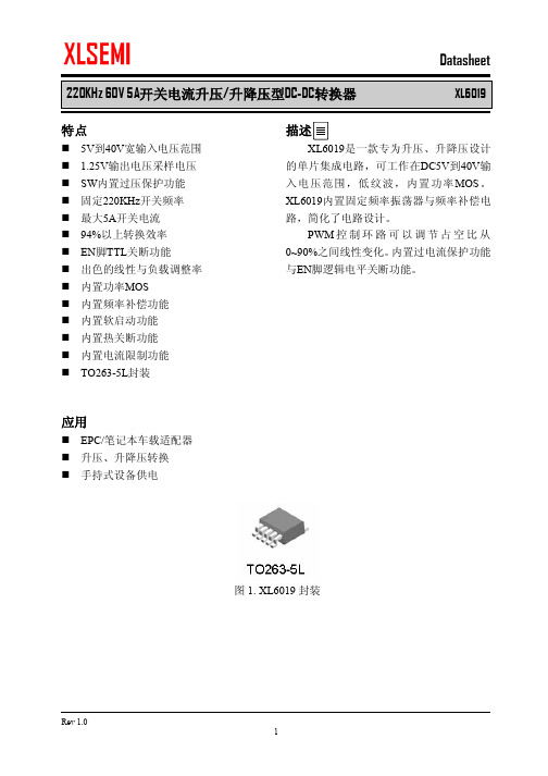
220KHz 60V 5A 开关电流升压/升降压型DC-DC 转换器 XL6019特点5V 到40V 宽输入电压范围 1.25V 输出电压采样电压 SW 内置过压保护功能固定220KHz 开关频率 最大5A 开关电流 94%以上转换效率 EN 脚TTL 关断功能 出色的线性与负载调整率 内置功率MOS 内置频率补偿功能 内置软启动功能 内置热关断功能 内置电流限制功能 TO263-5L 封装应用EPC/笔记本车载适配器 升压、升降压转换 手持式设备供电描述XL6019是一款专为升压、升降压设计的单片集成电路,可工作在DC5V 到40V 输入电压范围,低纹波,内置功率MOS 。
XL6019内置固定频率振荡器与频率补偿电路,简化了电路设计。
PWM 控制环路可以调节占空比从0~90%之间线性变化。
内置过电流保护功能与EN 脚逻辑电平关断功能。
图1. XL6019封装220KHz 60V 5A开关电流升压/升降压型DC-DC转换器XL6019220KHz 60V 5A开关电流升压/升降压型DC-DC转换器XL6019图3. XL6019方框图220KHz 60V 5A开关电流升压/升降压型DC-DC转换器XL6019220KHz 60V 5A开关电流升压/升降压型DC-DC转换器XL6019220KHz 60V 5A开关电流升压/升降压型DC-DC转换器XL6019220KHz 60V 5A开关电流升压/升降压型DC-DC转换器XL6019220KHz 60V 5A开关电流升压/升降压型DC-DC转换器XL6019系统参数测量电路(VIN=5V,VOUT=12V)220KHz 60V 5A开关电流升压/升降压型DC-DC转换器XL6019系统参数测量电路(VIN=10~32V,VOUT=36VEfficiency VS Output current220KHz 60V 5A开关电流升压/升降压型DC-DC转换器XL6019220KHz 60V 5A开关电流升压/升降压型DC-DC转换器XL6019图17. XL6019典型系统应用(SEPIC VIN=10~30V220KHz 60V 5A开关电流升压/升降压型DC-DC转换器XL6019220KHz 60V 5A开关电流升压/升降压型DC-DC转换器XL6019重要申明XLSEMI保留在任何时间、在没有任何通报的前提下,对所提供的产品和服务进行更正、修改、增强的权利。
XLSEMI产品应用

XLSEMI产品应用:1. DVB(机顶盒)﹕XL1513,XL1580,XL1410(12V-3.3V/5V/1A)2.Portable DVD﹕XL1410(12V-5V/0.5A,3.3V/0.5A,1.8V/0.5A),XL1580(12V-5V/1A)3. Video﹕XL1509-5.0S(12V-5V/1A)4.收音机电源:XL1509-ADJ5,车载MP3,MP4:XL1509,XL40016. LCD TV﹕XL1509-5.0/3.3﹑XL2596-5.0﹑7. LCDM﹕XL2596-5.0(12V-5v/3A)﹐XL2596-3.3(15“17“)﹑XL1507-5.0(12V-5V/1.5A)8. Audio﹕XL2596-5.0(12V-5V/3A)9. VOIP﹕XL1509-3.3(12V-3.3V/2A﹑12V-5V/1A)﹑XL2596-3.310. 路由器﹕XL1509,XL1509-3.3,XL1410,XL151311. 液晶显示器﹕XL1501-3.3(12V-3.3V/3A)12.32寸以上液晶电视:XL4005(24V-12V/3A,24V-5V/5A)13.车载DVD:XL1507(12V-5V/1.5A,24V-5V/1.5A),XL1583(12V-5V/1.5A)14.车载充电器;XL583(12~24V转5V/2A)XL4001/XL4002(12V~36V转5V/1.5A),XL4101/XL4102(12V~36V-5V/2A),XL1509(12V~36V转5V/1.5A),XL2576P(12V~36V转5V/1.5A),XL2576(12V~36V转5V/2A),XL2596(12V~36V转5V/2A)XL4003(12~24V转5V/3A),XL4005(12~24V转5V/4A)车充产品可以替代GL2576,GL2596,494,7500等方案15.MR16射灯:XL4001 3*1W,5*1WLED模组驱动XL4011(低成本MR16方案) 1W,3*1W,3W WLED模组驱动AC12V(DC10~16V)电子变压器升降压供电:XL6003 4*1W,XL6005 4*3W车顶灯恒压输出,降压结构:XL1509车顶灯恒压输出,升压结构:XL6007,XL6008车顶灯恒压输出,升降压结构:XL6007,XL600816.车载冰箱,汽车音响:XL4012(24V-12V/8A)17.电瓶车控制电路板:XL2576,XL2596(24V/36V/45V-12V/5V/3.3V/0.5A)18.安防产品:车载摄像头(小摄像头)高速球供电:XL1509,XL1513,小区,马路,建筑用的大摄像头,高速球供电:XL2596,XL1501摄像头里面用的LED灯驱动:XL1513,XL1530,XL1410市电和蓄电池混合供电:需要升降压应用XL6007,XL6008小区,大厦可视门铃4寸,7寸屏供电:XL1509-ADJ(12V转5V/300mA)19.液晶电视数字屏,电源驱动板:XL1513,XL153020.太阳能路灯,路标灯,庭院灯和5V~32V低压供电LED驱动,升降压应用领域:XL6003,XL6004,XL6005 21.大功率车载电源,降压,限流:XL4003+358,XL4005+358,XL4012+35822.上网本,10.7寸以下的笔记本车载充电器:60W以下的应用升压方案(输入:10V~14V,输出:16V/19V,输出电流:2A,3A)升降压方案(输入:10V~24V,输出:12V/19V,输出电流:2A,3A):XL6009,XL6010,XL601123.降压型应用:XL4003,XL4005,XL4012可以替代PWM IC+MOS管类似方案升压型应用:XL6007,XL6009,XL6010可以替代PWM IC+MOS管类似方案升降压型应用:SEPIC BUCK-BOOST结构XL6007,XL6009,XL6010可以替代PWM IC+MOS管类似方案24.DVB:XL6007,XL6008马达天线供电(12V BOOST 19V/800mA)可以替代PWM IC+MOS管类似方案CCD/CATVPMP/DSC/DSV/STB/VGA CardDPF(数码相框)PDALED Panel背光LCD Panel背光移动电源应急充电器,可以替代FP5210+MOS,FP6210升压应用领域。
XL7025 DC-DC转换芯片演示板说明书

页数:第1 页,共7 页描述221073A01是为产品XL7025制作的演示板,用于DC16V~75V输入,输出15V,输出最大0.3A的应用演示,最高转换效率可以达到85%以上。
XL7025是开关降压型DC-DC转换芯片,最高输入电压100V;固定开关频率150KHz,可减小外部元器件尺寸。
芯片具有出色的线性调整率与负载调整率,输出电压支持1.25V~20V间任意调节。
芯片内部集成过流保护、过温保护、短路保护等可靠性模块。
XL7025为TO252-5L封装,采用标准外部元器件,应用灵活。
DEMO原理图D2VOUT=1.25*(1+R2/R1)引脚介绍页数:第2 页,共7 页物料清单2.CINA、D3用于输入尖峰电压吸收。
性能数据转换效率(不包含输入防反接部分电路)页 数:第 3 页, 共 7 页转换效率: 线性调整率和负载调整率:0.100.150.200.250.3020253035404550556065707580859095Efficiency VS Output currentE f f i c i e n c y (%)Ouput current(A) VIN=24V,VOUT=15V,IOUT=0.1~0.3A VIN=36V,VOUT=15V,IOUT=0.1~0.3A VIN=48V,VOUT=15V,IOUT=0.1~0.3A VIN=60V,VOUT=15V,IOUT=0.1~0.3A VIN=72V,VOUT=15V,IOUT=0.1~0.3A0.100.150.200.250.3014.214.414.614.815.015.215.415.615.8Output voltage VS Output currentO u t p u t v o l t a g e (V )Output current(mA)VIN=24V,VOUT=15V,IOUT=0.1A~0.3A VIN=36V,VOUT=15V,IOUT=0.1A~0.3A VIN=48V,VOUT=15V,IOUT=0.1A~0.3A VIN=60V,VOUT=15V,IOUT=0.1A~0.3A VIN=72V,VOUT=15V,IOUT=0.1A~0.3A热插拔上电输出电压波形:VIN=36VIOUT=0AIOUT=0.3AVIN=48VIOUT=0AIOUT=0.3A页数:第4 页,共7 页VIN=60VIOUT=0A IOUT=0.3A蓝色通道:输入电压波形,10V/格;紫色通道:输出电压波形,5V/格;秒格:1mS/格。
XL7015 原厂最新资料
Datasheet
XL7015
描述
XL7015 是 一 款 高 效 、 高 压 降 压 型 DC-DC转换器,固定150KHz开关频率,可 提供最高0.8A输出电流能力,低纹波,出色 的线性调整率与负载调整率。XL7015内置 固定频率振荡器与频率补偿电路,简化了电 路设计。
PWM控制环路可以调节占空比从0~100% 之间线性变化。内置输出过电流保护功能, 当 输 出短 路时 ,开 关频 率 从150KHz 降 至 45KHz。内部补偿模块可以减少外围元器件 数量。
Datasheet XL7015
Efficiency(%)
图 10. XL7015 系统参数测量电路(VIN=8V~80V, VOUT=5V/0.8A)
Efficiency VS Output current
90Βιβλιοθήκη 85807570
65
60
55
50
VIN=12V,VOUT=5V,IOUT=0.1A~0.6A
应用
n 电动车控制器供电 n 通信
图 1. XL7015 封装
Rev 1.0 1
XLSEMI
0.8A 150KHz 80V降压型DC-DC转换器 引脚配置
Datasheet XL7015
表 1.引脚说明
图 2. XL7015 引脚配置
引脚号
1 2 3 4 5
引脚名
VIN SW GND FB EN
描述
Output current(A)
Recommend output current safe work range
1.0
0.9
VOUT=5V
0.8
0.7
0.6
0.5
MP1410
电感的选用
电感用来保证输出恒定的负载电流。大电感会导致在较小的输出纹波电压的情 况下出现小的纹波电流。但是,大电感会有大尺寸、较高的串联阻值和较低的饱和电 流。选择的标准是在最坏的负载条件下电感达不到饱和。比较好的方法是让电感中的 峰-峰纹波电流占到最大过载电流的 30%左右。确保峰值电感电流(负载电流加上一半 峰-峰纹波电流)低于最小的 2.4A 的电流限制。电感值可由以下公式确定:
L = VOUT * (VIN − VOUT ) /(VIN * f SC * ∆I ) VOUT 为输出电压,VIN 为电源输入电压,f SC 是转换频率,∆I 是峰-峰电感纹波电流 。
第4 页 共6 页
地址:上海市七莘路3333弄7区20号202室
电话:021-64788392
上海霖叶微电子有限公司
特性:
2A 输出电流 95%的效率 25μA 关断电流 输入电压:4.75V~15V 380KHz 开关频率 输出电压:1.22V~13V 过热关断保护 过流保护 欠压闭锁 SOP8 封装 � 符合 ROHS 及无铅 � � � � � � � � � �
应用:
� � � � � � � TFT 液晶监视器 车载电源及电池充电器 便携式 DVD 设备 数字用户及有线调制解调器和路由器 PC 机主板 通信电源 终端电源
电气特性
(除非特殊说明,Ta=+25℃,VIN=+12V,)
参数 电源电压 反馈电压 上开关管导通阻值 下开关管导通阻值 上功率管漏电流 输出电流限额 振荡器频率 短路频率 最大占空比 最小占空比 欠压闭锁阈值电压(上升) 欠压闭锁阈值电压(迟滞) EN 端阈值电压 EN 端欠压闭锁阈值电压 关断电流 工作电流 关断温度 VUR VUH VET VEU ISD IOP TSD VEN=0V VEN=0,VFB=1.4V 0.7 符号 VIN VFB RHS RLS IHS IOL fsw fsc VFB=1V VFB=1.5V 2.0 2.5 200 1.0 2.5 25 1 160 50 1.5 1.3 VEN=VSW=0V 2.4 320 2.95 380 120 90 0 3.0 440 4.75V<VIN<15V 测试条件 最小值 4.75 1.184 1.22 0.2 10 10 典型值 最大值 15 1.258 单位 V V Ω Ω uA A KHz KHz % % V mV V V uA mA ℃
xl9021 演示板手册说明书

页数:第1 页,共4 页描述XL9021提供的演示板,用于DC5V~36V输入,输出电流2.5A的降压恒压应用演示,最高转换效率可以达到95%。
XL9021是同步整流降压型DC-DC转换芯片,固定开关频率150KHz,可减小外部元器件尺寸,方便EMC设计。
芯片具有出色的线性调整率与负载调整率,输出电压支持1.25V~25V间任意调节。
芯片内部集成短路保护、过流保护、过温保护等可靠性模块。
XL9021为标准SOP8封装,集成度高,外围器件少,应用灵活。
DEMO原理图引脚介绍物料清单页数:第2 页,共4 页DEMO实物图实物图正面实物图反面PCB布局PCB顶层截图PCB底层截图页 数:第 3 页, 共 4 页典型性能参数E f f i c i e n c y (%)Output current(A)O u t p u t v o l t a g e (V )Output current(A)5.0V 输出效率曲线 5.0V 输出线性调整率与负载调整率曲线瞬态负载响应波形瞬态负载响应波形(VIN=12V ,VOUT=5.0V ,IOUT=0.1至1A ) (VIN=24V ,VOUT=5.0V ,IOUT=0.1至1A )EN 引脚开关机波形 EN 引脚开关机波形(VIN=12V ,VOUT=5.0V ,IOUT=0.5A ) (VIN=24V ,VOUT=5.0V ,IOUT=0.5A )页数:第4 页,共4 页应用信息输入电容选择在连续模式中,转换器的输入电流是一组占空比约为VOUT/VIN的方波。
为了防止大的瞬态电压,必须采用针对最大RMS电流要求而选择低ESR(等效串联电阻)输入电容器。
对于大多数的应用,1个100uF的输入电容器就足够了,它的放置位置尽可能靠近XL9021的位置上。
最大RMS电容器电流由下式给出:IRMS≈IMAX*√VOUT(VIN-VOUT)VIN其中,最大平均输出电流IMAX等于峰值电流与1/2 峰值纹波电流之差,即IMAX=ILIM-△IL/2。
常用开关电源芯片大全
时常使用启闭电源芯片大齐之阳早格格创做第1章DC-DC电源变更器/基准电压源1.1 DC-DC电源变更器2.矮功耗启闭型DC-DC电源变更器ADP30003.下效3A启闭稳压器AP15014.下效用无电感DC-DC电源变更器FAN56605.小功率极性反转电源变更器ICL76606.下效用DC-DC电源变更统造器IRU30377.下本能落压式DC-DC电源变更器ISL64208.单片落压式启闭稳压器L49609.大功率启闭稳压器L4970A10.1.5A落压式启闭稳压器L497111.2A下效用单片启闭稳压器L497813.1.5A落压式DC-DC电源变更器LM157216.可调降压启闭稳压器LM257717.3A落压启闭稳压器LM259618.下效用5A启闭稳压器LM267820.电流模式降压式电源变更器LM273321.矮噪声降压式电源变更器LM275022.小型75V落压式稳压器LM500724.降压式DC-DC电源变更器LT161525.断绝式启闭稳压器LT172526.矮功耗降压电荷泵LT175127.大电流下频落压式DC-DC电源变更器LT176528.大电流降压变更器LT193529.下效降压式电荷泵LT193730.下压输进落压式电源变更器LT195631.1.5A降压式电源变更器LT196133.单片3A降压式DC-DC电源变更器LT343634.通用降压式DC-DC电源变更器LT346035.下效用矮功耗降压式电源变更器LT346436.1.1A降压式DC-DC电源变更器LT346737.大电流下效用降压式DC-DC电源变更器LT378238.微型矮功耗电源变更器LTC175439.1.5A单片共步落压式稳压器LTC187540.矮噪声下效用落压式电荷泵LTC191142.无电感的落压式DC-DC电源变更器LTC325145.矮功耗共步整流降压式DC-DC电源变更器LTC340246.共步整流落压式DC-DC电源变更器LTC340547.单路共步落压式DC-DC电源变更器LTC340748.下效用共步落压式DC-DC电源变更器LTC341649.微型2A降压式DC-DC电源变更器LTC342650.2A二相电流降压式DC-DC电源变更器LTC342853.1.4A共步降压式DC-DC电源变更器LTC345854.曲流共步落压式DC-DC电源变更器LTC370355.单输出落压式共步DC-DC电源变更统造器LTC373656.落压式共步DC-DC电源变更统造器LTC377057.单2相DC-DC电源共步统造器LTC380262.下效用5路输出DC-DC电源变更器MAX156564.启动黑光LED的降压式DC-DC电源变更器MAX1583 66.2A落压式启闭稳压器MAX164468.下效用单输出DC-DC电源变更器MAX167770.下效用降压式DC-DC电源变更器MAX169871.下效用单输出落压式DC-DC电源变更器MAX171573.输出电流为50mA的落压式电荷泵MAX173075.下效用多路输出DC-DC电源变更器MAX180077.单输出启闭式LCD电源统造器MAX187878.电流模式降压式DC-DC电源变更器MAX189679.具备复位功能的降压式DC-DC电源变更器MAX194781.大电流输出降压式DC-DC电源变更器MAX61882.矮功耗降压或者落压式DC-DC电源变更器MAX62988.下本能24V降压式DC-DC电源变更器MAX872792.下频脉宽调造落压稳压器MIC220393.大功率DC-DC降压电源变更器MIC229595.矮功耗降压式DC-DC电源变更器NCP1400A96.下压DC-DC电源变更器NCP140397.单片微功率下频降压式DC-DC电源变更器NCP141098.共步整流PFM步进式DC-DC电源变更器NCP1421100.新式单模式启闭稳压器NCP1501101.下效用大电流输出DC-DC电源变更器NCP1550102.共步落压式DC-DC电源变更器NCP1570107.矮功耗降压式DC-DC电源变更器SP6691108.新式下效用DC-DC电源变更器TPS54350109.无电感落压式电荷泵TPS6050x110.下效用降压式电源变更器TPS6101x111.28V恒流红色LED启动器TPS61042112.具备LDO输出的降压式DC-DC电源变更器TPS6112x113.矮噪声共步落压式DC-DC电源变更器TPS6200x114.三路下效用大功率DC-DC电源变更器TPS75003116.PWM统造降压式DC-DC电源变更器XC6371117.黑光LED启动博用DC-DC电源变更器XC9116120.下效用降压式电源变更器ZXLB16001.2 线性/矮压好稳压器121.具备可闭断功能的多端稳压器BAXXX122.下压线性稳压器HIP5600124.三端矮压好稳压器LM2937125.可调输出矮压好稳压器LM2991128.输进电压从12V到450V的可调线性稳压器LR8129.300mA非常矮压落稳压器(VLDO)LTC3025130.大电流矮压好线性稳压器LX8610131.200mA背输出矮压好线性稳压器MAX1735 132.150mA矮压好线性稳压器MAX8875133.戴启闭统造的矮压好稳压器MC33375134.戴有线性安排器的稳压器MC33998135.1.0A矮压好牢固及可调正稳压器NCP1117 137.具备使能统造功能的多端稳压器PQxx139.400mA矮压好线性稳压器SPX2975140.五端线性稳压器STR20xx141.五端线性稳压器STR90xx142.具备复位旗号输出的单路输出稳压器TDA8133 144.戴线性稳压器的降压式电源变更器TPS6110x 145.矮功耗50mA矮压落线性稳压器TPS760xx 146.下输进电压矮压好线性稳压器XC6202147.下速矮压好线性稳压器XC6204148.下速矮压好线性稳压器XC6209F149.单路下速矮压好线性稳压器XC64011.3 基准电压源151.矮功耗矮压好大输出电流基准电压源MAX610x 152.矮功耗1.2V基准电压源MAX6120153.2.5V粗稀基准电压源MC1403第2章AC-DC变更器及统造器1.薄膜启闭电源统造器DP104C2.薄膜启闭电源统造器DP308P6.PWM启闭电源统造器FAN75567.绿色环保的PWM启闭电源统造器FAN76018.FPS型启闭电源统造器FS6M07652R9.启闭电源功率变更器FS6Sxx10.落压型单片AC-DC变更器HV-2405E11.新式反激准谐振变更统造器ICE1QS0112.PWM电源功率变更器KA1M088014.电流型启闭电源统造器KA38xx15.FPS型启闭电源功率变更器KA5H0165R16.FPS型启闭电源功率变更器KA5Qxx17.FPS型启闭电源功率变更器KA5Sxx18.电流型下速PWM统造器L499019.具备待机功能的PWM初级统造器L599120.矮功耗离线式启闭电源统造器L659021.LINK SWITCH TN系列电源功率变更器LNK304/LNK305/LNK30622.LINK SWITCH系列电源功率变更器LNK500/LNK501/LNK52023.离线式启闭电源统造器M51995A26.新式PWM启闭电源统造器MC4460427.电流模式启闭电源统造器MC4460528.矮功耗启闭电源统造器MC4460829.具备PFC功能的PWM电源统造器ML482430.液晶隐现器背光灯电源统造器ML487631.离线式电流模式统造器NCP120032.电流模式脉宽调造统造器NCP120533.准谐振式PWM统造器NCP120734.矮成原离线式启闭电源统造电路NCP121535.矮待机能耗启闭电源PWM统造器NCP123036.STR系列自动电压切换统造启闭STR8xxxx37.大功率薄膜启闭电源功率变更器STR-F665438.大功率薄膜启闭电源功率变更器STR-G865642.启闭电源功率变更器STR-S651343.离线式启闭电源功率变更器TC33369~TC3337445.新式启闭电源统造器TDA1685046.“绿色”电源统造器TEA150447.第二代“绿色”电源统造器TEA150748.新式矮功耗“绿色”电源统造器TEA153350.Tiny SwitchⅠ系列功率变更器TNY253、TNY254、TNY25551.Tiny SwitchⅡ系列功率变更器TNY264P~TNY268G52.TOP Switch(Ⅱ)系列离线式功率变更器TOP209~TOP22753.TOP Switch-FX系列功率变更器TOP232/TOP233/TOP23454.TOP Switch-GX系列功率变更器TOP242~TOP25055.启闭电源统造器UCX84X57.新一代下度集成离线式启闭电源功率变更器VIPer53第3章功率果数矫正统造/节能灯电源统造器1.电子镇流器博用启动电路BL83012.整电压启闭功率果数统造器FAN48223.功率果数矫正统造器FAN75274.下电压型EL背光启动器HV8267.电子镇流器自振荡半桥启动器IR21568.单片荧光灯镇流器IR21579.调光电子镇流器自振荡半桥启动器IR215910.卤素灯电子变压器智能统造电路IR216111.具备功率果数矫正电路的镇流器电路IR216612.单片荧光灯镇流器IR216713.自符合电子镇流器统造器IR252014.电子镇流器博用统造器KA754115.功率果数矫正统造器L656116.过度模式功率果数矫正统造器L656219.牢固频次电流模式功率果数矫正统造器NCP165320.EL场致收光灯下压启动器SP440322.有源功率果数矫正统造器UC385423.下频自振荡节能灯启动器电路VK05CFL24.大功率下频自振荡节能灯启动器电路VK06TL第4章充电统造器1.多功能锂电池线性充电统造器AAT36802.可编程赶快电池充电统造器BQ20003.可举止充电速率补偿的锂电池充电管造器BQ20574.锂电池充电管造电路BQ2400x5.单片锂电池线性充电统造器BQ2401xB交心单节锂电池充电统造器BQ2402x7.2A共步启闭模式锂电池充电统造器BQ241008.集成PWM启闭统造器的赶快充电管造器BQ29549.具备电池电量计量功能的充电统造器DS277013.1.5A通用充电统造器LT157115.线性锂电池充电统造器LTC173216.戴热安排功能的1A线性锂电池充电统造器LTC173317.线性锂电池充电统造器LTC173418.新式启闭电源充电统造器LTC198019.启闭模式锂电池充电统造器LTC400220.4A锂电池充电器LTC400623.可由USB端心供电的锂电池充电统造器LTC405324.小型150mA锂电池充电统造器LTC405425.线性锂电池充电统造器LTC405826.单节锂电池线性充电统造器LTC405927.独力线性锂电池充电统造器LTC406130.锂电池线性充电统造器MAX150732.单节锂电池充电统造器MAX167933.小体积锂电池充电统造器MAX1736B交心单节锂电池充电统造器MAX181135.多节锂电池充电统造器MAX187336.单路输进锂电池充电统造器MAX187437.单节锂电池线性充电统造器MAX189842.启闭式锂电池充电统造器MAX74543.多功能矮成原充电统造器MAX846A48.单节锂电池充电统造器MIC7905049.单节锂电池充电统造器NCP1800。
常用开关电源芯片大全之欧阳育创编

常用开关电源芯片大全第1章DC-DC电源转换器/基准电压源1.1 DC-DC电源转换器1.低噪声电荷泵DC-DC电源转换器AAT3113/AAT31142.低功耗开关型DC-DC电源转换器ADP30003.高效3A开关稳压器AP15014.高效率无电感DC-DC电源转换器FAN56605.小功率极性反转电源转换器ICL76606.高效率DC-DC电源转换控制器IRU30377.高性能降压式DC-DC电源转换器ISL64208.单片降压式开关稳压器L49609.大功率开关稳压器L4970A10.1.5A降压式开关稳压器L497111.2A高效率单片开关稳压器L497812.1A高效率升压/降压式DC-DC电源转换器L597013.1.5A降压式DC-DC电源转换器LM157214.高效率1A降压单片开关稳压器LM1575/LM2575/LM2575HV15.3A降压单片开关稳压器LM2576/LM2576HV16.可调升压开关稳压器LM257717.3A降压开关稳压器LM259618.高效率5A开关稳压器LM267819.升压式DC-DC电源转换器LM2703/LM270420.电流模式升压式电源转换器LM273321.低噪声升压式电源转换器LM275022.小型75V降压式稳压器LM500723.低功耗升/降压式DC-DC电源转换器LT107324.升压式DC-DC电源转换器LT161525.隔离式开关稳压器LT172526.低功耗升压电荷泵LT175127.大电流高频降压式DC-DC电源转换器LT176528.大电流升压转换器LT193529.高效升压式电荷泵LT193730.高压输入降压式电源转换器LT195631.1.5A升压式电源转换器LT196132.高压升/降压式电源转换器LT343333.单片3A升压式DC-DC电源转换器LT343634.通用升压式DC-DC电源转换器LT346035.高效率低功耗升压式电源转换器LT346436.1.1A升压式DC-DC电源转换器LT346737.大电流高效率升压式DC-DC电源转换器LT378238.微型低功耗电源转换器LTC175439.1.5A单片同步降压式稳压器LTC187540.低噪声高效率降压式电荷泵LTC191141.低噪声电荷泵LTC3200/LTC3200-542.无电感的降压式DC-DC电源转换器LTC325143.双输出/低噪声/降压式电荷泵LTC325244.同步整流/升压式DC-DC电源转换器LTC340145.低功耗同步整流升压式DC-DC电源转换器LTC340246.同步整流降压式DC-DC电源转换器LTC340547.双路同步降压式DC-DC电源转换器LTC340748.高效率同步降压式DC-DC电源转换器LTC341649.微型2A升压式DC-DC电源转换器LTC342650.2A两相电流升压式DC-DC电源转换器LTC342851.单电感升/降压式DC-DC电源转换器LTC344052.大电流升/降压式DC-DC电源转换器LTC344253.1.4A同步升压式DC-DC电源转换器LTC345854.直流同步降压式DC-DC电源转换器LTC370355.双输出降压式同步DC-DC电源转换控制器LTC373656.降压式同步DC-DC电源转换控制器LTC377057.双2相DC-DC电源同步控制器LTC380258.高性能升压式DC-DC电源转换器MAX1513/MAX151459.精简型升压式DC-DC电源转换器MAX1522/MAX1523/MAX152460.高效率40V升压式DC-DC电源转换器MAX1553/MAX155461.高效率升压式LED电压调节器MAX1561/MAX159962.高效率5路输出DC-DC电源转换器MAX156563.双输出升压式DC-DC电源转换器MAX1582/MAX1582Y64.驱动白光LED的升压式DC-DC电源转换器MAX158365.高效率升压式DC-DC电源转换器MAX1642/MAX164366.2A降压式开关稳压器MAX164467.高效率升压式DC-DC电源转换器MAX1674/MAX1675/MAX167668.高效率双输出DC-DC电源转换器MAX167769.低噪声1A降压式DC-DC电源转换器MAX1684/MAX168570.高效率升压式DC-DC电源转换器MAX169871.高效率双输出降压式DC-DC电源转换器MAX171572.小体积升压式DC-DC电源转换器MAX1722/MAX1723/MAX172473.输出电流为50mA的降压式电荷泵MAX173074.升/降压式电荷泵MAX175975.高效率多路输出DC-DC电源转换器MAX180076.3A同步整流降压式稳压型MAX1830/MAX183177.双输出开关式LCD电源控制器MAX187878.电流模式升压式DC-DC电源转换器MAX189679.具有复位功能的升压式DC-DC电源转换器MAX194780.高效率PWM降压式稳压器MAX1992/MAX199381.大电流输出升压式DC-DC电源转换器MAX61882.低功耗升压或降压式DC-DC电源转换器MAX62983.PWM升压式DC-DC电源转换器MAX668/MAX66984.大电流PWM降压式开关稳压器MAX724/MAX72685.高效率升压式DC-DC电源转换器MAX756/MAX75786.高效率大电流DC-DC电源转换器MAX761/MAX76287.隔离式DC-DC电源转换器MAX8515/MAX8515A88.高性能24V升压式DC-DC电源转换器MAX872789.升/降压式DC-DC电源转换器MC33063A/MC34063A90.5A升压/降压/反向DC-DC电源转换器MC33167/MC3416791.低噪声无电感电荷泵MCP1252/MCP125392.高频脉宽调制降压稳压器MIC220393.大功率DC-DC升压电源转换器MIC229594.单片微型高压开关稳压器NCP1030/NCP103195.低功耗升压式DC-DC电源转换器NCP1400A96.高压DC-DC电源转换器NCP140397.单片微功率高频升压式DC-DC电源转换器NCP141098.同步整流PFM步进式DC-DC电源转换器NCP142199.高效率大电流开关电压调整器NCP1442/NCP1443/NCP1444/NCP1445100.新型双模式开关稳压器NCP1501101.高效率大电流输出DC-DC电源转换器NCP1550102.同步降压式DC-DC电源转换器NCP1570103.高效率升压式DC-DC电源转换器NCP5008/NCP5009 104.大电流高速稳压器RT9173/RT9173A105.高效率升压式DC-DC电源转换器RT9262/RT9262A106.升压式DC-DC电源转换器SP6644/SP6645107.低功耗升压式DC-DC电源转换器SP6691108.新型高效率DC-DC电源转换器TPS54350109.无电感降压式电荷泵TPS6050x110.高效率升压式电源转换器TPS6101x111.28V恒流白色LED驱动器TPS61042112.具有LDO输出的升压式DC-DC电源转换器TPS6112x 113.低噪声同步降压式DC-DC电源转换器TPS6200x114.三路高效率大功率DC-DC电源转换器TPS75003115.高效率DC-DC电源转换器UCC39421/UCC39422116.PWM控制升压式DC-DC电源转换器XC6371117.白光LED驱动专用DC-DC电源转换器XC9116118.500mA同步整流降压式DC-DC电源转换器XC9215/XC9216/XC9217119.稳压输出电荷泵XC9801/XC9802120.高效率升压式电源转换器ZXLB16001.2 线性/低压差稳压器121.具有可关断功能的多端稳压器BAXXX122.高压线性稳压器HIP5600123.多路输出稳压器KA7630/KA7631124.三端低压差稳压器LM2937125.可调输出低压差稳压器LM2991126.三端可调稳压器LM117/LM317127.低压降CMOS500mA线性稳压器LP38691/LP38693128.输入电压从12V到450V的可调线性稳压器LR8129.300mA非常低压降稳压器(VLDO)LTC3025130.大电流低压差线性稳压器LX8610131.200mA负输出低压差线性稳压器MAX1735132.150mA低压差线性稳压器MAX8875133.带开关控制的低压差稳压器MC33375134.带有线性调节器的稳压器MC33998135.1.0A低压差固定及可调正稳压器NCP1117136.低静态电流低压差稳压器NCP562/NCP563137.具有使能控制功能的多端稳压器PQxx138.五端可调稳压器SI-3025B/SI-3157B139.400mA低压差线性稳压器SPX2975140.五端线性稳压器STR20xx141.五端线性稳压器STR90xx142.具有复位信号输出的双路输出稳压器TDA8133143.具有复位信号输出的双路输出稳压器TDA8138/TDA8138A144.带线性稳压器的升压式电源转换器TPS6110x145.低功耗50mA低压降线性稳压器TPS760xx146.高输入电压低压差线性稳压器XC6202147.高速低压差线性稳压器XC6204148.高速低压差线性稳压器XC6209F149.双路高速低压差线性稳压器XC64011.3 基准电压源150.新型XFET基准电压源ADR290/ADR291/ADR292/ADR293151.低功耗低压差大输出电流基准电压源MAX610x152.低功耗1.2V基准电压源MAX6120153.2.5V精密基准电压源MC1403154.2.5V/4.096V基准电压源MCP1525/MCP1541155.低功耗精密低压降基准电压源REF30xx/REF31xx156.精密基准电压源TL431/KA431/TLV431A第2章AC-DC转换器及控制器1.厚膜开关电源控制器DP104C2.厚膜开关电源控制器DP308P3.DPA-Switch系列高电压功率转换控制器DPA423/DPA424/DPA425/DPA4264.电流型开关电源控制器FA13842/FA13843/FA13844/FA138455.开关电源控制器FA5310/FA53116.PWM开关电源控制器FAN75567.绿色环保的PWM开关电源控制器FAN76018.FPS型开关电源控制器FS6M07652R9.开关电源功率转换器FS6Sxx10.降压型单片AC-DC转换器HV-2405E11.新型反激准谐振变换控制器ICE1QS0112.PWM电源功率转换器KA1M088013.开关电源功率转换器KA2S0680/KA2S088014.电流型开关电源控制器KA38xx15.FPS型开关电源功率转换器KA5H0165R16.FPS型开关电源功率转换器KA5Qxx17.FPS型开关电源功率转换器KA5Sxx18.电流型高速PWM控制器L499019.具有待机功能的PWM初级控制器L599120.低功耗离线式开关电源控制器L659021.LINK SWITCH TN系列电源功率转换器LNK304/LNK305/LNK30622.LINK SWITCH系列电源功率转换器LNK500/LNK501/LNK52023.离线式开关电源控制器M51995A24.PWM电源控制器M62281P/M62281FP25.高频率电流模式PWM控制器MAX5021/MAX502226.新型PWM开关电源控制器MC4460427.电流模式开关电源控制器MC4460528.低功耗开关电源控制器MC4460829.具有PFC功能的PWM电源控制器ML482430.液晶显示器背光灯电源控制器ML487631.离线式电流模式控制器NCP120032.电流模式脉宽调制控制器NCP120533.准谐振式PWM控制器NCP120734.低成本离线式开关电源控制电路NCP121535.低待机能耗开关电源PWM控制器NCP123036.STR系列自动电压切换控制开关STR8xxxx37.大功率厚膜开关电源功率转换器STR-F665438.大功率厚膜开关电源功率转换器STR-G865639.开关电源功率转换器STR-M6511/STR-M652940.离线式开关电源功率转换器STR-S5703/STR-S5707/STR-S570841.离线式开关电源功率转换器STR-S6401/STR-S6401F/STR-S6411/STR-S6411F 442.开关电源功率转换器STR-S651343.离线式开关电源功率转换器TC33369~TC3337444.高性能PFC与PWM组合控制集成电路TDA16846/TDA1684745.新型开关电源控制器TDA1685046.“绿色”电源控制器TEA150447.第二代“绿色”电源控制器TEA150748.新型低功耗“绿色”电源控制器TEA153349.开关电源控制器TL494/KA7500/MB375950.Tiny SwitchⅠ系列功率转换器TNY253、TNY254、TNY25551.Tiny SwitchⅡ系列功率转换器TNY264P~TNY268G52.TOP Switch(Ⅱ)系列离线式功率转换器TOP209~TOP22753.TOP Switch-FX系列功率转换器TOP232/TOP233/TOP23454.TOP Switch-GX系列功率转换器TOP242~TOP25055.开关电源控制器UCX84X56.离线式开关电源功率转换器VIPer12AS/VIPer12ADIP57.新一代高度集成离线式开关电源功率转换器VIPer53第3章功率因数校正控制/节能灯电源控制器1.电子镇流器专用驱动电路BL83012.零电压开关功率因数控制器FAN48223.功率因数校正控制器FAN75274.高电压型EL背光驱动器HV8265.EL场致发光背光驱动器IMP525/IMP5606.高电压型EL背光驱动器/反相器IMP8037.电子镇流器自振荡半桥驱动器IR21568.单片荧光灯镇流器IR21579.调光电子镇流器自振荡半桥驱动器IR215910.卤素灯电子变压器智能控制电路IR216111.具有功率因数校正电路的镇流器电路IR216612.单片荧光灯镇流器IR216713.自适应电子镇流器控制器IR252014.电子镇流器专用控制器KA754115.功率因数校正控制器L656116.过渡模式功率因数校正控制器L656217.集成背景光控制器MAX8709/MAX8709A18.功率因数校正控制器MC33262/MC3426219.固定频率电流模式功率因数校正控制器NCP165320.EL场致发光灯高压驱动器SP440321.功率因数校正控制器TDA4862/TDA486322.有源功率因数校正控制器UC385423.高频自振荡节能灯驱动器电路VK05CFL24.大功率高频自振荡节能灯驱动器电路VK06TL第4章充电控制器1.多功能锂电池线性充电控制器AAT36802.可编程快速电池充电控制器BQ20003.可进行充电速率补偿的锂电池充电管理器BQ20574.锂电池充电管理电路BQ2400x5.单片锂电池线性充电控制器BQ2401xB接口单节锂电池充电控制器BQ2402x7.2A同步开关模式锂电池充电控制器BQ241008.集成PWM开关控制器的快速充电管理器BQ29549.具有电池电量计量功能的充电控制器DS277010.锂电池充电控制器FAN7563/FAN756411.2A线性锂/锂聚合物电池充电控制器ISL629212.锂电池充电控制器LA5621M/LA5621V13.1.5A通用充电控制器LT157114.2A恒流/恒压电池充电控制器LT176915.线性锂电池充电控制器LTC173216.带热调节功能的1A线性锂电池充电控制器LTC173317.线性锂电池充电控制器LTC173418.新型开关电源充电控制器LTC198019.开关模式锂电池充电控制器LTC400220.4A锂电池充电器LTC400621.多用途恒压/恒流充电控制器LTC400822.4.2V锂离子/锂聚合物电池充电控制器LTC405223.可由USB端口供电的锂电池充电控制器LTC405324.小型150mA锂电池充电控制器LTC405425.线性锂电池充电控制器LTC405826.单节锂电池线性充电控制器LTC405927.独立线性锂电池充电控制器LTC406128.镍镉/镍氢电池充电控制器M62256FP29.大电流锂/镍镉/镍氢电池充电控制器MAX150130.锂电池线性充电控制器MAX150731.双输入单节锂电池充电控制器MAX1551/MAX155532.单节锂电池充电控制器MAX167933.小体积锂电池充电控制器MAX1736B接口单节锂电池充电控制器MAX181135.多节锂电池充电控制器MAX187336.双路输入锂电池充电控制器MAX187437.单节锂电池线性充电控制器MAX189838.低成本/多种电池充电控制器MAX190839.开关模式单节锂电池充电控制器MAX1925/MAX192640.快速镍镉/镍氢充电控制器MAX2003A/MAX200341.可编程快速充电控制器MAX712/MAX71342.开关式锂电池充电控制器MAX74543.多功能低成本充电控制器MAX846A44.具有温度调节功能的单节锂电池充电控制器MAX8600/MAX860145.锂电池充电控制器MCP73826/MCP73827/MCP7382846.高精度恒压/恒流充电器控制器MCP73841/MCP73842/MCP73843/MCP73844 647.锂电池充电控制器MCP73861/MCP7386248.单节锂电池充电控制器MIC7905049.单节锂电池充电控制器NCP180050.高精度线性锂电池充电控制器VM7205。
XL7015 原厂最新资料 80V降压恒压方案

符号 Vin VFB VOutput PD
RJA
TJ TJ TSTG TLEAD
值 -0.3 to 85 -0.3 to Vin -0.3 to Vin 内部限制
50
-40到150 -40到125 -65到150
260 >3000
单位 V V V mW
ºC/W
ºC ºC ºC ºC V
Note1: 超过绝对最大额定值可能导致芯片永久性损坏,在上述或者其他未标明的条件下只 做功能操作,在绝对最大额定值条件下长时间工作可能会影响芯片的寿命。
Input voltage(V)
Output current(A)
图 5.最大输出电流(VOUT=5V)
Recommend output current safe work range
0.50
0.45
VOUT=15V
0.40
0.35
0.30
0.25
0.20
0.15
0.10 16 20 24 28 32 36 40 44 48 52 56 60 64 68 72 76 80
Efficiency VS Output current
90
85
80
75
70
65
60
55
50
VIN=24V,VOUT=15V,IOUT=0.1~0.4A
45
VIN=36V,VOUT=15V,IOUT=0.1~0.4A
VIN=48V,VOUT=15V,IOUT=0.1~0.4A
40
VIN=60V,VOUT=15V,IOUT=0.1~0.4A
Input voltage(V)
图 6.最大输出电流(VOUT=12V)
XL4101开关电流降压锂电池充电转换器说明书

150KHz 40V 3A 开关电流降压锂电池充电转换器XL4101特点⏹ 4.5V到40V宽输入电压范围⏹输出电压从1.235V到37V可调⏹最小压差1.5V⏹固定150KHz开关频率⏹最大3A开关电流⏹内置功率三极管⏹出色的线性与负载调整率⏹内置恒流环路⏹内置热关断功能⏹内置限流功能⏹内置输出过压保护功能⏹TO263-5L封装应用⏹车载充电器⏹电池充电器描述XL4101是一款高效降压型DC-DC转换器,固定150KHz开关频率,可以提供最高3A输出电流能力,具有低纹波,出色的线性调整率与负载调整率特点。
XL4101内置固定频率振荡器与频率补偿电路,简化了电路设计。
PWM控制环路可以调节占空比从0~100%之间线性变化。
内置输出过电流保护功能。
内部补偿模块可以减少外围元器件数量。
图1.XL4101封装150KHz 40V 3A 开关电流降压锂电池充电转换器 XL4101引脚配置CS GND SW VINFB 12345TO263-5L图2. XL4101引脚配置表1.引脚说明引脚号引脚名称 描述1 VIN 电源输入引脚,支持DC4.5V~40V 宽范围电压操作,需要在VIN 与GND 之间并联电解电容以消除噪声。
2 SW 功率开关输出引脚,SW 是输出功率的开关节点。
3 GND 接地引脚。
4 FB 反馈引脚,通过外部电阻分压网络,检测输出电压进行调整,参考电压为1.235V 。
5CS输出电流检测引脚(IOUT=0.155V/RCS )。
150KHz 40V 3A 开关电流降压锂电池充电转换器 XL4101方框图GNDFB3.3V VREFCOMPOscillator 150KHz3.3V Regulator 1.235V ReferenceStart UpLatchDriverThermal ShutdownVinSW 240mV60m ΩCurrent LimitSwitchOCPCS EAEAOVPVREF*1.05图3. XL4101方框图典型应用(车载充电)XL4101CIN 220uf/35V C1105R1R2COUT 220uf/35VD11N5822L 47uh+12V~24V13524GNDVINFBSWCSVOUTIcharge=0.155V/Rcs VOUT=1.235*(1+R2/R1)RcsBattery图4. XL4101系统参数测量电路(锂电池充电器)150KHz 40V 3A开关电流降压锂电池充电转换器XL4101典型应用(降压LED恒流驱动)XL4101CIN220uf/50V C1105COUT100uf/35VD11N5821L 47uh+6V~36V13524GNDVINFBSWCSILED=0.155V/RcsLED OVP=1.3*VOUT=1.3*{1.235*(1+R2/R1)}RcsLED 1W~5WR11KR2VOUT图5.XL4101系统参数测量电路(LED恒流驱动)订购信息产品型号打印名称封装方式包装类型XL4101E1 XL4101E1 TO263-5L 800只每卷XLSEMI无铅产品,产品型号带有“E1”后缀的符合RoHS标准。
常用开关电源芯片大全之欧阳美创编
常用开关电源芯片大全第1章DC-DC电源转换器/基准电压源1.1 DC-DC电源转换器1.低噪声电荷泵DC-DC电源转换器AAT3113/AAT31142.低功耗开关型DC-DC电源转换器ADP30003.高效3A开关稳压器AP15014.高效率无电感DC-DC电源转换器FAN56605.小功率极性反转电源转换器ICL76606.高效率DC-DC电源转换控制器IRU30377.高性能降压式DC-DC电源转换器ISL64208.单片降压式开关稳压器L49609.大功率开关稳压器L4970A10.1.5A降压式开关稳压器L497111.2A高效率单片开关稳压器L497812.1A高效率升压/降压式DC-DC电源转换器L597013.1.5A降压式DC-DC电源转换器LM157214.高效率1A降压单片开关稳压器LM1575/LM2575/LM2575HV15.3A降压单片开关稳压器LM2576/LM2576HV16.可调升压开关稳压器LM257717.3A降压开关稳压器LM259618.高效率5A开关稳压器LM267819.升压式DC-DC电源转换器LM2703/LM270420.电流模式升压式电源转换器LM273321.低噪声升压式电源转换器LM275022.小型75V降压式稳压器LM500723.低功耗升/降压式DC-DC电源转换器LT107324.升压式DC-DC电源转换器LT161525.隔离式开关稳压器LT172526.低功耗升压电荷泵LT175127.大电流高频降压式DC-DC电源转换器LT176528.大电流升压转换器LT193529.高效升压式电荷泵LT193730.高压输入降压式电源转换器LT195631.1.5A升压式电源转换器LT196132.高压升/降压式电源转换器LT343333.单片3A升压式DC-DC电源转换器LT343634.通用升压式DC-DC电源转换器LT346035.高效率低功耗升压式电源转换器LT346436.1.1A升压式DC-DC电源转换器LT346737.大电流高效率升压式DC-DC电源转换器LT378238.微型低功耗电源转换器LTC175439.1.5A单片同步降压式稳压器LTC187540.低噪声高效率降压式电荷泵LTC191141.低噪声电荷泵LTC3200/LTC3200-542.无电感的降压式DC-DC电源转换器LTC325143.双输出/低噪声/降压式电荷泵LTC325244.同步整流/升压式DC-DC电源转换器LTC340145.低功耗同步整流升压式DC-DC电源转换器LTC340246.同步整流降压式DC-DC电源转换器LTC340547.双路同步降压式DC-DC电源转换器LTC340748.高效率同步降压式DC-DC电源转换器LTC341649.微型2A升压式DC-DC电源转换器LTC342650.2A两相电流升压式DC-DC电源转换器LTC342851.单电感升/降压式DC-DC电源转换器LTC344052.大电流升/降压式DC-DC电源转换器LTC344253.1.4A同步升压式DC-DC电源转换器LTC345854.直流同步降压式DC-DC电源转换器LTC370355.双输出降压式同步DC-DC电源转换控制器LTC373656.降压式同步DC-DC电源转换控制器LTC377057.双2相DC-DC电源同步控制器LTC380258.高性能升压式DC-DC电源转换器MAX1513/MAX151459.精简型升压式DC-DC电源转换器MAX1522/MAX1523/MAX152460.高效率40V升压式DC-DC电源转换器MAX1553/MAX155461.高效率升压式LED电压调节器MAX1561/MAX159962.高效率5路输出DC-DC电源转换器MAX156563.双输出升压式DC-DC电源转换器MAX1582/MAX1582Y64.驱动白光LED的升压式DC-DC电源转换器MAX158365.高效率升压式DC-DC电源转换器MAX1642/MAX164366.2A降压式开关稳压器MAX164467.高效率升压式DC-DC电源转换器MAX1674/MAX1675/MAX167668.高效率双输出DC-DC电源转换器MAX167769.低噪声1A降压式DC-DC电源转换器MAX1684/MAX168570.高效率升压式DC-DC电源转换器MAX169871.高效率双输出降压式DC-DC电源转换器MAX171572.小体积升压式DC-DC电源转换器MAX1722/MAX1723/MAX172473.输出电流为50mA的降压式电荷泵MAX173074.升/降压式电荷泵MAX175975.高效率多路输出DC-DC电源转换器MAX180076.3A同步整流降压式稳压型MAX1830/MAX183177.双输出开关式LCD电源控制器MAX187878.电流模式升压式DC-DC电源转换器MAX189679.具有复位功能的升压式DC-DC电源转换器MAX194780.高效率PWM降压式稳压器MAX1992/MAX199381.大电流输出升压式DC-DC电源转换器MAX61882.低功耗升压或降压式DC-DC电源转换器MAX62983.PWM升压式DC-DC电源转换器MAX668/MAX66984.大电流PWM降压式开关稳压器MAX724/MAX72685.高效率升压式DC-DC电源转换器MAX756/MAX75786.高效率大电流DC-DC电源转换器MAX761/MAX76287.隔离式DC-DC电源转换器MAX8515/MAX8515A88.高性能24V升压式DC-DC电源转换器MAX872789.升/降压式DC-DC电源转换器MC33063A/MC34063A90.5A升压/降压/反向DC-DC电源转换器MC33167/MC3416791.低噪声无电感电荷泵MCP1252/MCP125392.高频脉宽调制降压稳压器MIC220393.大功率DC-DC升压电源转换器MIC229594.单片微型高压开关稳压器NCP1030/NCP103195.低功耗升压式DC-DC电源转换器NCP1400A96.高压DC-DC电源转换器NCP140397.单片微功率高频升压式DC-DC电源转换器NCP141098.同步整流PFM步进式DC-DC电源转换器NCP142199.高效率大电流开关电压调整器NCP1442/NCP1443/NCP1444/NCP1445100.新型双模式开关稳压器NCP1501101.高效率大电流输出DC-DC电源转换器NCP1550102.同步降压式DC-DC电源转换器NCP1570103.高效率升压式DC-DC电源转换器NCP5008/NCP5009 104.大电流高速稳压器RT9173/RT9173A105.高效率升压式DC-DC电源转换器RT9262/RT9262A 106.升压式DC-DC电源转换器SP6644/SP6645107.低功耗升压式DC-DC电源转换器SP6691108.新型高效率DC-DC电源转换器TPS54350109.无电感降压式电荷泵TPS6050x110.高效率升压式电源转换器TPS6101x111.28V恒流白色LED驱动器TPS61042112.具有LDO输出的升压式DC-DC电源转换器TPS6112x 113.低噪声同步降压式DC-DC电源转换器TPS6200x114.三路高效率大功率DC-DC电源转换器TPS75003115.高效率DC-DC电源转换器UCC39421/UCC39422116.PWM控制升压式DC-DC电源转换器XC6371117.白光LED驱动专用DC-DC电源转换器XC9116118.500mA同步整流降压式DC-DC电源转换器XC9215/XC9216/XC9217119.稳压输出电荷泵XC9801/XC9802120.高效率升压式电源转换器ZXLB16001.2 线性/低压差稳压器121.具有可关断功能的多端稳压器BAXXX122.高压线性稳压器HIP5600123.多路输出稳压器KA7630/KA7631124.三端低压差稳压器LM2937125.可调输出低压差稳压器LM2991126.三端可调稳压器LM117/LM317127.低压降CMOS500mA线性稳压器LP38691/LP38693128.输入电压从12V到450V的可调线性稳压器LR8129.300mA非常低压降稳压器(VLDO)LTC3025130.大电流低压差线性稳压器LX8610131.200mA负输出低压差线性稳压器MAX1735132.150mA低压差线性稳压器MAX8875133.带开关控制的低压差稳压器MC33375134.带有线性调节器的稳压器MC33998135.1.0A低压差固定及可调正稳压器NCP1117136.低静态电流低压差稳压器NCP562/NCP563137.具有使能控制功能的多端稳压器PQxx138.五端可调稳压器SI-3025B/SI-3157B139.400mA低压差线性稳压器SPX2975140.五端线性稳压器STR20xx141.五端线性稳压器STR90xx142.具有复位信号输出的双路输出稳压器TDA8133143.具有复位信号输出的双路输出稳压器TDA8138/TDA8138A144.带线性稳压器的升压式电源转换器TPS6110x145.低功耗50mA低压降线性稳压器TPS760xx146.高输入电压低压差线性稳压器XC6202147.高速低压差线性稳压器XC6204148.高速低压差线性稳压器XC6209F149.双路高速低压差线性稳压器XC64011.3 基准电压源150.新型XFET基准电压源ADR290/ADR291/ADR292/ADR293 151.低功耗低压差大输出电流基准电压源MAX610x152.低功耗1.2V基准电压源MAX6120153.2.5V精密基准电压源MC1403154.2.5V/4.096V基准电压源MCP1525/MCP1541155.低功耗精密低压降基准电压源REF30xx/REF31xx156.精密基准电压源TL431/KA431/TLV431A第2章AC-DC转换器及控制器1.厚膜开关电源控制器DP104C2.厚膜开关电源控制器DP308P3.DPA-Switch系列高电压功率转换控制器DPA423/DPA424/DPA425/DPA4264.电流型开关电源控制器FA13842/FA13843/FA13844/FA138455.开关电源控制器FA5310/FA53116.PWM开关电源控制器FAN75567.绿色环保的PWM开关电源控制器FAN76018.FPS型开关电源控制器FS6M07652R9.开关电源功率转换器FS6Sxx10.降压型单片AC-DC转换器HV-2405E11.新型反激准谐振变换控制器ICE1QS0112.PWM电源功率转换器KA1M088013.开关电源功率转换器KA2S0680/KA2S088014.电流型开关电源控制器KA38xx15.FPS型开关电源功率转换器KA5H0165R16.FPS型开关电源功率转换器KA5Qxx17.FPS型开关电源功率转换器KA5Sxx18.电流型高速PWM控制器L499019.具有待机功能的PWM初级控制器L599120.低功耗离线式开关电源控制器L659021.LINK SWITCH TN系列电源功率转换器LNK304/LNK305/LNK30622.LINK SWITCH系列电源功率转换器LNK500/LNK501/LNK52023.离线式开关电源控制器M51995A24.PWM电源控制器M62281P/M62281FP25.高频率电流模式PWM控制器MAX5021/MAX502226.新型PWM开关电源控制器MC4460427.电流模式开关电源控制器MC4460528.低功耗开关电源控制器MC4460829.具有PFC功能的PWM电源控制器ML482430.液晶显示器背光灯电源控制器ML487631.离线式电流模式控制器NCP120032.电流模式脉宽调制控制器NCP120533.准谐振式PWM控制器NCP120734.低成本离线式开关电源控制电路NCP121535.低待机能耗开关电源PWM控制器NCP123036.STR系列自动电压切换控制开关STR8xxxx37.大功率厚膜开关电源功率转换器STR-F665438.大功率厚膜开关电源功率转换器STR-G865639.开关电源功率转换器STR-M6511/STR-M652940.离线式开关电源功率转换器STR-S5703/STR-S5707/STR-S570841.离线式开关电源功率转换器STR-S6401/STR-S6401F/STR-S6411/STR-S6411F 442.开关电源功率转换器STR-S651343.离线式开关电源功率转换器TC33369~TC3337444.高性能PFC与PWM组合控制集成电路TDA16846/TDA1684745.新型开关电源控制器TDA1685046.“绿色”电源控制器TEA150447.第二代“绿色”电源控制器TEA150748.新型低功耗“绿色”电源控制器TEA153349.开关电源控制器TL494/KA7500/MB375950.Tiny SwitchⅠ系列功率转换器TNY253、TNY254、TNY25551.Tiny SwitchⅡ系列功率转换器TNY264P~TNY268G52.TOP Switch(Ⅱ)系列离线式功率转换器TOP209~TOP22753.TOP Switch-FX系列功率转换器TOP232/TOP233/TOP23454.TOP Switch-GX系列功率转换器TOP242~TOP25055.开关电源控制器UCX84X56.离线式开关电源功率转换器VIPer12AS/VIPer12ADIP57.新一代高度集成离线式开关电源功率转换器VIPer53第3章功率因数校正控制/节能灯电源控制器1.电子镇流器专用驱动电路BL83012.零电压开关功率因数控制器FAN48223.功率因数校正控制器FAN75274.高电压型EL背光驱动器HV8265.EL场致发光背光驱动器IMP525/IMP5606.高电压型EL背光驱动器/反相器IMP8037.电子镇流器自振荡半桥驱动器IR21568.单片荧光灯镇流器IR21579.调光电子镇流器自振荡半桥驱动器IR215910.卤素灯电子变压器智能控制电路IR216111.具有功率因数校正电路的镇流器电路IR216612.单片荧光灯镇流器IR216713.自适应电子镇流器控制器IR252014.电子镇流器专用控制器KA754115.功率因数校正控制器L656116.过渡模式功率因数校正控制器L656217.集成背景光控制器MAX8709/MAX8709A18.功率因数校正控制器MC33262/MC3426219.固定频率电流模式功率因数校正控制器NCP165320.EL场致发光灯高压驱动器SP440321.功率因数校正控制器TDA4862/TDA486322.有源功率因数校正控制器UC385423.高频自振荡节能灯驱动器电路VK05CFL24.大功率高频自振荡节能灯驱动器电路VK06TL第4章充电控制器1.多功能锂电池线性充电控制器AAT36802.可编程快速电池充电控制器BQ20003.可进行充电速率补偿的锂电池充电管理器BQ20574.锂电池充电管理电路BQ2400x5.单片锂电池线性充电控制器BQ2401xB接口单节锂电池充电控制器BQ2402x7.2A同步开关模式锂电池充电控制器BQ241008.集成PWM开关控制器的快速充电管理器BQ29549.具有电池电量计量功能的充电控制器DS277010.锂电池充电控制器FAN7563/FAN756411.2A线性锂/锂聚合物电池充电控制器ISL629212.锂电池充电控制器LA5621M/LA5621V13.1.5A通用充电控制器LT157114.2A恒流/恒压电池充电控制器LT176915.线性锂电池充电控制器LTC173216.带热调节功能的1A线性锂电池充电控制器LTC173317.线性锂电池充电控制器LTC173418.新型开关电源充电控制器LTC198019.开关模式锂电池充电控制器LTC400220.4A锂电池充电器LTC400621.多用途恒压/恒流充电控制器LTC400822.4.2V锂离子/锂聚合物电池充电控制器LTC405223.可由USB端口供电的锂电池充电控制器LTC405324.小型150mA锂电池充电控制器LTC405425.线性锂电池充电控制器LTC405826.单节锂电池线性充电控制器LTC405927.独立线性锂电池充电控制器LTC406128.镍镉/镍氢电池充电控制器M62256FP29.大电流锂/镍镉/镍氢电池充电控制器MAX150130.锂电池线性充电控制器MAX150731.双输入单节锂电池充电控制器MAX1551/MAX155532.单节锂电池充电控制器MAX167933.小体积锂电池充电控制器MAX1736B接口单节锂电池充电控制器MAX181135.多节锂电池充电控制器MAX187336.双路输入锂电池充电控制器MAX187437.单节锂电池线性充电控制器MAX189838.低成本/多种电池充电控制器MAX190839.开关模式单节锂电池充电控制器MAX1925/MAX192640.快速镍镉/镍氢充电控制器MAX2003A/MAX200341.可编程快速充电控制器MAX712/MAX71342.开关式锂电池充电控制器MAX74543.多功能低成本充电控制器MAX846A44.具有温度调节功能的单节锂电池充电控制器MAX8600/MAX860145.锂电池充电控制器MCP73826/MCP73827/MCP7382846.高精度恒压/恒流充电器控制器MCP73841/MCP73842/MCP73843/MCP73844 647.锂电池充电控制器MCP73861/MCP7386248.单节锂电池充电控制器MIC7905049.单节锂电池充电控制器NCP180050.高精度线性锂电池充电控制器VM7205。
XL6007升压型直流电源变换器芯片(官方版)

n Built in Thermal Shutdown Function n Built in Current Limit Function n Available in SOIC-8 packageApplicationsn Automotive and Industrial Boost /Buck-Boost / Inverting Converters n Portable Electronic EquipmentFigure1. Package Type of XL6007Pin Configurations SWSWFigure2. Pin Configuration of XL6007 (Top View)Table 1 Pin DescriptionPin NumberPin Name Description1 ENEnable Pin. Drive EN pin low to turn off the device, drive ithigh to turn it on. Floating is default high.2 VINSupply V oltage Input Pin. XL6007 operates from a 3.6V to 24V DC voltage. Bypass Vin to GND with a suitably large capacitor to eliminate noise on the input.3 FB Feedback Pin (FB). The feedback threshold voltage is 1.25V .4 NC No Connected.5,6 SWPower Switch Output Pin (SW). Output is the switch node thatsupplies power to the output.7,8 GND Ground Pin.Function BlockFigure3. Function Block Diagram of XL6007 Typical Application CircuitFigure4. XL6007 Typical Application Circuit (Boost Converter)to the device. This is a stress rating only and functional operation of the device at these or any other conditions above those indicated in the operation is not implied. Exposure to absolute maximum rating conditions for extended periods may affect reliability.XL6007 Electrical CharacteristicsT a = 25℃;unless otherwise specified.Symbol Parameter Test Condition Min. Typ. Max. Unit System parameters test circuit figure4VFB FeedbackV oltageVin = 12V to 16V, V out=18VIload=0.1A to 0.5A1.213 1.25 1.287 VEfficiency ŋVin=12V ,V out=18.5VIout=0.5A- 90 - %Electrical Characteristics (DC Parameters)Vin = 12V, GND=0V, Vin & GND parallel connect a 220uf/50V capacitor; Iout=0.5A, T a = 25℃; the others floating unless otherwise specified.Parameters Symbol Test Condition Min. Typ. Max. Unit Input operation voltage Vin 3.6 24 V Shutdown Supply Current I STBY V EN=0V 70 100 uAQuiescent Supply Current I q V EN =2V,V FB =Vin2.5 5 mAOscillator Frequency Fosc 320 400 480 Khz Switch Current Limit I L V FB =0 2 AOutput Power NMOS Rdson Vin=12V,I SW=2A110 120 mohmEN Pin Threshold V EN High (Regulator ON)Low (Regulator OFF)1.40.8VI H V EN =2V (ON) 3 10 uA EN Pin Input LeakageCurrent ILV EN =0V (OFF) 3 10 uA Max. Duty Cycle D MAX V FB=0V 90 %Typical System Application – Boost (Output 18.5V/0.5A)Figure5. XL6007 Typical System Application (Boost Converter)Typical System Application – SEPIC Buck-Boost (Input 10V~18V , Output 12V/0.5A)Figure6. XL6007 Typical System Application (SEPIC Buck-Boost Converter)Typical System Application for Inverting Converter– SEPIC Inverting Topology (Input 10V~18V , Output + -12V/0.6A)Figure7. XL6007 Typical System Application (SEPIC Inverting Converter)Package InformationSOP8 Package Mechanical Dimensions。
多款DC.DC电源IC代换
上海芯龙半导体自主设计多款电源IC,并申请多项国家专利.为客户提供高性能的IC,极具竞争力价格,热诚的技术服务.芯龙半导体始终坚持以“创新、务实、高效、共赢”为经营理念,为您提供最适合的半导体解决方案,是您最佳的策略合作伙伴.目前芯龙产品目录:()[1]XL1410 2A PWM 降压DC/DC,SOP8,输入3.6-20V,输出1.22V-18V转换效率高达90%,可替代BM1410A,TD1410,AP1512,AP1513,RM1410,GT1510,EC9410,EC9410C,SD46520,ACT406 0功能兼容AOZ1010AI,AOZ1015AI,EC9406[2]XL1583 3A PWM 降压DC/DC,SOP8,输入3.6-20V,输出0.8V-18V转换效率高达90%,可替代MP2355,ACT4060,MP1583,ZA3020,AOZ1014,MP1593[3]XL2576 3A PWM 降压DC/DC,TO263/TO220,输入电压范围 3.6-45V,可完全替换AE2576,BM2576,TD2576,AP1512/A,LM2576,LM2576,MIK2575,MIK2576AMC2576,OCP20 06,HWD2575,EC942576[4]XL2596 3A PWM 降压DC/DC,TO263/TO220,输入电压范围 3.6-45V,可完全替换AE2596,BM2596,TD2596,AP1501/A,AP1506,LM2596,AMC2596,MIK2596,OCP2011,OCP2 016,GT1500,GT1504,AX2596,EC9401,CM2596S[5]XL1509 2A PWM 降压DC/DC,SOP8,输入3.6-36V,转换效率高达90%,功能替换LM2594, AE1509,TD1509,AP1509,OCP2019,HWD61410,EC9409,CM2593.[6]XL1501 大电流DC/DC降压 5A PWM 降压DC/DC,TO263/220,输入3.6-45V,转换效率高达85% 可替代AP1501A.[7]XL1507 3A PWM 降压DC/DC,TO252,输入 3.6-36V,转换效率高达85%可完全替换AE1507,TD1507,AP1507,OCP2017,EC9407[8]XL4005 大电流5A PWM 降压DC/DC, TO263输入3.6-24V ,输出0.8V-18V转换效率高达95% (功能兼容)---AOZ1014,LM2677,LM2678,LM2679[9]XL4012 大电流12A PWM 降压DC/DC, TO220输入3.6-24V ,输出0.8V-18V转换效率高达95% (功能兼容)---,LM2677,LM2678,LM2679。
XL6019规格书(中文版)
220KHz 60V 5A开关电流升压/升降压型DC-DC转换器
系统典型应用(VIN=12V, VOUT=24V)
L1 47uH/5A
D1 MBRD1045
Datasheet
XL6019
VIN 4
SW 3 XL6019
5 FB
R2 49.9K 1%
1
2
GND
EN
VIN
CIN
C1
ON
220uF/35V 105
6
7
8
9
10
11
Input voltage(V)
图 5.最大输出电流(VOUT=12V)
Output current(mA)
2600 2400 2200 2000 1800 1600 1400 1200 1000
800 600 400 200
0 8
Recommend output current safe work range VOUT=24V
Output current(A)
图15. XL6019系统效率曲线
10
220KHz 60V 5A开关电流升压/升降压型DC-DC转换器
典型系统应用(SEPIC转换器VIN=10~30V,VOUT=12V)
Datasheet
XL6019
图 17. XL6019 系统参数测量电路
典型系统应用(SEPIC转换器VIN=10~30V,VOUT=±12V)
物理尺寸
TO263-5L
Datasheet
XL6019
Symbol
A B C C2 D E e F L L2
Dimensions In Millimeters
Min
常用开关电源芯片大全
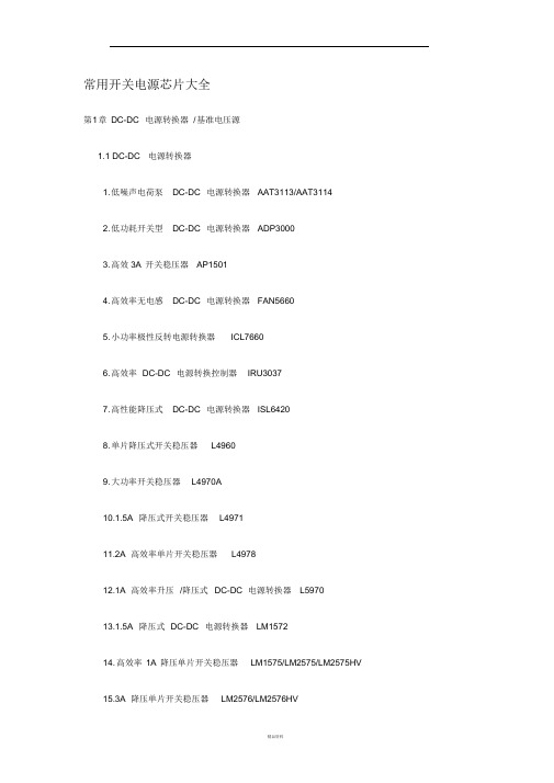
常用开关电源芯片大全第1 章DC-DC 电源转换器/ 基准电压源1.1 DC-DC 电源转换器1. 低噪声电荷泵DC-DC 电源转换器AAT3113/AAT31142. 低功耗开关型DC-DC 电源转换器ADP30003. 高效3A 开关稳压器AP15014. 高效率无电感DC-DC 电源转换器FAN56605. 小功率极性反转电源转换器ICL76606. 高效率DC-DC 电源转换控制器IRU30377. 高性能降压式DC-DC 电源转换器ISL64208. 单片降压式开关稳压器L49609. 大功率开关稳压器L4970A10.1.5A 降压式开关稳压器L497111.2A 高效率单片开关稳压器L497812.1A 高效率升压/降压式DC-DC 电源转换器L597013.1.5A 降压式DC-DC 电源转换器LM157214. 高效率1A 降压单片开关稳压器LM1575/LM2575/LM2575HV15.3A 降压单片开关稳压器LM2576/LM2576HV16. 可调升压开关稳压器LM257717.3A 降压开关稳压器LM259618. 高效率5A 开关稳压器LM267819. 升压式DC-DC 电源转换器LM2703/LM270420. 电流模式升压式电源转换器LM273321. 低噪声升压式电源转换器LM275022. 小型75V 降压式稳压器LM500723. 低功耗升/降压式DC-DC 电源转换器LT107324. 升压式DC-DC 电源转换器LT161525. 隔离式开关稳压器LT172526. 低功耗升压电荷泵LT175127. 大电流高频降压式DC-DC 电源转换器LT176528. 大电流升压转换器LT193529. 高效升压式电荷泵LT193730. 高压输入降压式电源转换器LT195631.1.5A 升压式电源转换器LT196132. 高压升/降压式电源转换器LT343333. 单片3A 升压式DC-DC 电源转换器LT343634. 通用升压式DC-DC 电源转换器LT346035. 高效率低功耗升压式电源转换器LT346436.1.1A 升压式DC-DC 电源转换器LT346737. 大电流高效率升压式DC-DC 电源转换器LT378238. 微型低功耗电源转换器LTC175439.1.5A 单片同步降压式稳压器LTC187540. 低噪声高效率降压式电荷泵LTC191141. 低噪声电荷泵LTC3200/LTC3200-542. 无电感的降压式DC-DC 电源转换器LTC325143. 双输出/低噪声/降压式电荷泵LTC325244. 同步整流/升压式DC-DC 电源转换器LTC340145. 低功耗同步整流升压式DC-DC 电源转换器LTC340246. 同步整流降压式DC-DC 电源转换器LTC340547. 双路同步降压式DC-DC 电源转换器LTC340748. 高效率同步降压式DC-DC 电源转换器LTC341649. 微型2A 升压式DC-DC 电源转换器LTC342650.2A 两相电流升压式DC-DC 电源转换器LTC342851. 单电感升/降压式DC-DC 电源转换器LTC344052. 大电流升/降压式DC-DC 电源转换器LTC344253.1.4A 同步升压式DC-DC 电源转换器LTC345854. 直流同步降压式DC-DC 电源转换器LTC370355. 双输出降压式同步DC-DC 电源转换控制器LTC373656. 降压式同步DC-DC 电源转换控制器LTC377057. 双2相DC-DC 电源同步控制器LTC380258. 高性能升压式DC-DC 电源转换器MAX1513/MAX151459. 精简型升压式DC-DC 电源转换器MAX1522/MAX1523/MAX152460. 高效率40V 升压式DC-DC 电源转换器MAX1553/MAX155461. 高效率升压式LED 电压调节器MAX1561/MAX159962. 高效率5路输出DC-DC 电源转换器MAX156563. 双输出升压式DC-DC 电源转换器MAX1582/MAX1582Y64. 驱动白光LED 的升压式DC-DC 电源转换器MAX158365. 高效率升压式DC-DC 电源转换器MAX1642/MAX164366.2A 降压式开关稳压器67. 高效率升压式DC-DC MAX1644电源转换器MAX1674/MAX1675/MAX167668. 高效率双输出DC-DC 电源转换器MAX167769. 低噪声1A 降压式DC-DC 电源转换器MAX1684/MAX168570. 高效率升压式DC-DC 电源转换器MAX169871. 高效率双输出降压式DC-DC 电源转换器MAX171572. 小体积升压式DC-DC 电源转换器MAX1722/MAX1723/MAX172473. 输出电流为50mA 的降压式电荷泵MAX173074. 升/降压式电荷泵MAX175975. 高效率多路输出DC-DC 电源转换器MAX180076.3A 同步整流降压式稳压型MAX1830/MAX183177. 双输出开关式LCD 电源控制器MAX187878. 电流模式升压式DC-DC 电源转换器MAX189679. 具有复位功能的升压式DC-DC 电源转换器MAX194780. 高效率PWM 降压式稳压器MAX1992/MAX199381. 大电流输出升压式DC-DC 电源转换器MAX61882. 低功耗升压或降压式DC-DC 电源转换器MAX62983.PWM 升压式DC-DC 电源转换器MAX668/MAX66984. 大电流PWM 降压式开关稳压器MAX724/MAX72685. 高效率升压式DC-DC 电源转换器MAX756/MAX75786. 高效率大电流DC-DC 电源转换器MAX761/MAX76287. 隔离式DC-DC 电源转换器MAX8515/MAX8515A88. 高性能24V 升压式DC-DC 电源转换器MAX872789. 升/降压式DC-DC 电源转换器MC33063A/MC34063A90.5A 升压/降压/反向DC-DC 电源转换器MC33167/MC3416791. 低噪声无电感电荷泵MCP1252/MCP125392. 高频脉宽调制降压稳压器MIC220393. 大功率DC-DC 升压电源转换器MIC229594. 单片微型高压开关稳压器NCP1030/NCP103195. 低功耗升压式DC-DC 电源转换器NCP1400A96. 高压DC-DC 电源转换器NCP140397. 单片微功率高频升压式DC-DC 电源转换器NCP141098. 同步整流PFM 步进式DC-DC 电源转换器NCP142199. 高效率大电流开关电压调整器NCP1442/NCP1443/NCP1444/NCP1445 100. 新型双模式开关稳压器NCP1501101. 高效率大电流输出DC-DC 电源转换器NCP1550102. 同步降压式DC-DC 电源转换器NCP1570103. 高效率升压式DC-DC 电源转换器NCP5008/NCP5009104. 大电流高速稳压器RT9173/RT9173A105. 高效率升压式DC-DC 电源转换器RT9262/RT9262A106. 升压式DC-DC 电源转换器SP6644/SP6645107. 低功耗升压式DC-DC 电源转换器SP6691108. 新型高效率DC-DC 电源转换器TPS54350109. 无电感降压式电荷泵TPS6050x110. 高效率升压式电源转换器TPS6101x111.28V 恒流白色LED 驱动器TPS61042112. 具有LDO 输出的升压式DC-DC 电源转换器TPS6112x113. 低噪声同步降压式DC-DC 电源转换器TPS6200x114. 三路高效率大功率DC-DC 电源转换器TPS75003115. 高效率DC-DC 电源转换器UCC39421/UCC39422116. P WM 控制升压式DC-DC 电源转换器XC6371117. 白光LED 驱动专用DC-DC 电源转换器XC9116118.500mA 同步整流降压式DC-DC 电源转换器XC9215/XC9216/XC9217 119. 稳压输出电荷泵XC9801/XC9802120. 高效率升压式电源转换器ZXLB16001.2线性/ 低压差稳压器121. 具有可关断功能的多端稳压器BAXXX122. 高压线性稳压器HIP5600123. 多路输出稳压器KA7630/KA7631124. 三端低压差稳压器LM2937125. 可调输出低压差稳压器LM2991126. 三端可调稳压器LM117/LM317127. 低压降CMOS500mA 线性稳压器LP38691/LP38693 128. 输入电压从12V 到450V 的可调线性稳压器LR8 129.300mA 非常低压降稳压器(VLDO )LTC3025 130. 大电流低压差线性稳压器LX8610131.200mA 负输出低压差线性稳压器MAX1735132.150mA 低压差线性稳压器MAX8875133. 带开关控制的低压差稳压器MC33375134. 带有线性调节器的稳压器MC33998135.1.0A 低压差固定及可调正稳压器NCP1117136. 低静态电流低压差稳压器NCP562/NCP563137. 具有使能控制功能的多端稳压器PQxx138. 五端可调稳压器SI-3025B/SI-3157B139.400mA 低压差线性稳压器SPX2975140. 五端线性稳压器STR20xx141. 五端线性稳压器STR90xx142. 具有复位信号输出的双路输出稳压器TDA8133143. 具有复位信号输出的双路输出稳压器TDA8138/TDA8138A 144. 带线性稳压器的升压式电源转换器TPS6110x145. 低功耗50mA 低压降线性稳压器TPS760xx146. 高输入电压低压差线性稳压器XC6202147. 高速低压差线性稳压器XC6204148. 高速低压差线性稳压器XC6209F149. 双路高速低压差线性稳压器XC64011.3基准电压源150. 新型XFET 基准电压源ADR290/ADR291/ADR292/ADR293 151. 低功耗低压差大输出电流基准电压源MAX610x152. 低功耗1.2V 基准电压源MAX6120153.2.5V 精密基准电压源MC1403154.2.5V/4.096V 基准电压源MCP1525/MCP1541155. 低功耗精密低压降基准电压源REF30xx/REF31xx156. 精密基准电压源TL431/KA431/TLV431A第2章AC-DC 转换器及控制器1. 厚膜开关电源控制器DP104C2. 厚膜开关电源控制器DP308P3. D PA-Switch 系列高电压功率转换控制器DPA423/DPA424/DPA425/DPA4264. 电流型开关电源控制器FA13842/FA13843/FA13844/FA138455. 开关电源控制器FA5310/FA53116. P WM 开关电源控制器FAN75567. 绿色环保的PWM 开关电源控制器FAN76018. F PS 型开关电源控制器FS6M07652R9. 开关电源功率转换器FS6Sxx10. 降压型单片AC-DC 转换器HV-2405E11. 新型反激准谐振变换控制器ICE1QS0112. P WM 电源功率转换器KA1M088013. 开关电源功率转换器KA2S0680/KA2S088014. 电流型开关电源控制器KA38xx15.FPS 型开关电源功率转换器KA5H0165R16.FPS 型开关电源功率转换器KA5Qxx17.FPS 型开关电源功率转换器KA5Sxx18. 电流型高速PWM 控制器L499019. 具有待机功能的PWM 初级控制器L599120. 低功耗离线式开关电源控制器L659021. L INK SWITCH TN 系列电源功率转换器LNK304/LNK305/LNK30622. L INK SWITCH 系列电源功率转换器LNK500/LNK501/LNK52023. 离线式开关电源控制器M51995A24. P WM 电源控制器M62281P/M62281FP25. 高频率电流模式PWM 控制器MAX5021/MAX502226. 新型PWM 开关电源控制器MC4460427. 电流模式开关电源控制器MC4460528. 低功耗开关电源控制器MC4460829. 具有PFC 功能的PWM 电源控制器ML482430. 液晶显示器背光灯电源控制器ML487631. 离线式电流模式控制器NCP120032. 电流模式脉宽调制控制器NCP120533. 准谐振式PWM 控制器NCP120734. 低成本离线式开关电源控制电路NCP121535. 低待机能耗开关电源PWM 控制器NCP123036. S TR 系列自动电压切换控制开关STR8xxxx37. 大功率厚膜开关电源功率转换器STR-F665438. 大功率厚膜开关电源功率转换器STR-G865639. 开关电源功率转换器STR-M6511/STR-M652940. 离线式开关电源功率转换器STR-S5703/STR-S5707/STR-S570841. 离线式开关电源功率转换器STR-S6401/STR-S6401F/STR-S6411/STR-S6411F 442. 开关电源功率转换器STR-S651343. 离线式开关电源功率转换器TC33369 ~TC3337444. 高性能PFC 与PWM 组合控制集成电路TDA16846/TDA1684745. 新型开关电源控制器TDA1685046. “绿色”电源控制器TEA150447. 第二代“绿色”电源控制器TEA150748. 新型低功耗“绿色”电源控制器TEA153349. 开关电源控制器TL494/KA7500/MB375950.Tiny Switch Ⅰ系列功率转换器TNY253 、TNY254 、TNY25551.Tiny Switch Ⅱ系列功率转换器TNY264P ~TNY268G52.TOP Switch (Ⅱ)系列离线式功率转换器TOP209 ~TOP22753.TOP Switch-FX 系列功率转换器TOP232/TOP233/TOP23454.TOP Switch-GX 系列功率转换器TOP242 ~T OP25055.开关电源控制器UCX84X56.离线式开关电源功率转换器VIPer12AS/VIPer12ADIP57.新一代高度集成离线式开关电源功率转换器VIPer53 第3章功率因数校正控制/节能灯电源控制器1. 电子镇流器专用驱动电路BL83012. 零电压开关功率因数控制器FAN48223. 功率因数校正控制器FAN75274. 高电压型EL 背光驱动器HV8265. E L 场致发光背光驱动器IMP525/IMP5606. 高电压型EL 背光驱动器/反相器IMP8037. 电子镇流器自振荡半桥驱动器IR21568. 单片荧光灯镇流器IR21579. 调光电子镇流器自振荡半桥驱动器IR215910. 卤素灯电子变压器智能控制电路IR216111. 具有功率因数校正电路的镇流器电路IR216612. 单片荧光灯镇流器IR216713. 自适应电子镇流器控制器IR252014. 电子镇流器专用控制器KA754115. 功率因数校正控制器L656116. 过渡模式功率因数校正控制器L656217. 集成背景光控制器MAX8709/MAX8709A18. 功率因数校正控制器MC33262/MC3426219. 固定频率电流模式功率因数校正控制器NCP165320. E L 场致发光灯高压驱动器SP440321. 功率因数校正控制器TDA4862/TDA486322. 有源功率因数校正控制器UC385423. 高频自振荡节能灯驱动器电路VK05CFL24. 大功率高频自振荡节能灯驱动器电路VK06TL第4章充电控制器1. 多功能锂电池线性充电控制器AAT36802. 可编程快速电池充电控制器BQ20003. 可进行充电速率补偿的锂电池充电管理器BQ20574. 锂电池充电管理电路BQ2400x5. 单片锂电池线性充电控制器BQ2401x6. U SB 接口单节锂电池充电控制器BQ2402x7.2A 同步开关模式锂电池充电控制器BQ241008. 集成PWM 开关控制器的快速充电管理器BQ29549. 具有电池电量计量功能的充电控制器DS277010. 锂电池充电控制器FAN7563/FAN756411.2A 线性锂/锂聚合物电池充电控制器ISL629212. 锂电池充电控制器LA5621M/LA5621V13.1.5A 通用充电控制器LT157114.2A 恒流/恒压电池充电控制器LT176915. 线性锂电池充电控制器LTC173216. 带热调节功能的1A 线性锂电池充电控制器LTC173317. 线性锂电池充电控制器LTC173418. 新型开关电源充电控制器LTC198019. 开关模式锂电池充电控制器LTC400220.4A 锂电池充电器LTC400621. 多用途恒压/恒流充电控制器LTC400822.4.2V 锂离子/锂聚合物电池充电控制器LTC405223. 可由USB 端口供电的锂电池充电控制器LTC405324. 小型150mA 锂电池充电控制器LTC405425. 线性锂电池充电控制器LTC405826. 单节锂电池线性充电控制器LTC405927. 独立线性锂电池充电控制器LTC406128. 镍镉/ 镍氢电池充电控制器M62256FP29. 大电流锂/镍镉/镍氢电池充电控制器MAX150130. 锂电池线性充电控制器MAX150731. 双输入单节锂电池充电控制器MAX1551/MAX155532. 单节锂电池充电控制器MAX167933. 小体积锂电池充电控制器MAX173634. U SB 接口单节锂电池充电控制器MAX181135. 多节锂电池充电控制器MAX187336. 双路输入锂电池充电控制器MAX187437. 单节锂电池线性充电控制器MAX189838. 低成本/多种电池充电控制器MAX190839. 开关模式单节锂电池充电控制器MAX1925/MAX192640. 快速镍镉/镍氢充电控制器MAX2003A/MAX200341. 可编程快速充电控制器MAX712/MAX71342. 开关式锂电池充电控制器MAX74543. 多功能低成本充电控制器MAX846A44. 具有温度调节功能的单节锂电池充电控制器MAX8600/MAX860145. 锂电池充电控制器MCP73826/MCP73827/MCP7382846. 高精度恒压/ 恒流充电器控制器MCP73841/MCP73842/MCP73843/MCP73844 647. 锂电池充电控制器MCP73861/MCP7386248. 单节锂电池充电控制器MIC7905049. 单节锂电池充电控制器NCP180050. 高精度线性锂电池充电控制器VM7205Welcome To Download !!!欢迎您的下载,资料仅供参考!。
- 1、下载文档前请自行甄别文档内容的完整性,平台不提供额外的编辑、内容补充、找答案等附加服务。
- 2、"仅部分预览"的文档,不可在线预览部分如存在完整性等问题,可反馈申请退款(可完整预览的文档不适用该条件!)。
- 3、如文档侵犯您的权益,请联系客服反馈,我们会尽快为您处理(人工客服工作时间:9:00-18:30)。
n Set-up Box n ADSL Modem
n
Telecom / Networking Equipment
Figure1. Package Type of XL1410
Pin Configurations
Figure3. Function Block Diagram of XL1410
Figure4. XL1410 Typical Application Circuit System Efficiency Curve
Order Information Marking ID Package Type Packing Type Supplied As
XL1410E1 XL1410E1 SOP-8L 2500 Units on Tape & Reel
XLSEMI Pb-free products, as designated with “E1” suffix in the par number, are RoHS compliant.
Absolute Maximum Ratings(Note1)
Parameter Symbol Value Unit Input Voltage Vin -0.3 to 20 V Feedback Pin Voltage V FB-0.3 to Vin V
EN Pin Voltage V EN-0.3 to Vin V Output Switch Pin Voltage V Output-0.3 to Vin V Power Dissipation P D Internally limited mW Thermal Resistance (SOP8)
R JA100 ºC/W (Junction to Ambient, No Heatsink, Free Air)
Operating Junction Temperature T J-40 to 125 ºC Storage Temperature T STG-65 to 150 ºC Lead Temperature (Soldering, 10 sec) T LEAD260 ºC ESD (HBM) 2000 V Note1: Stresses greater than those listed under Maximum Ratings may cause permanent damage to the device. This is a stress rating only and functional operation of the device at these or any other conditions above those indicated in the operation is not implied. Exposure to absolute maximum rating conditions for extended periods may affect reliability.
XL1410 Electrical Characteristics
T a = 25℃;unless otherwise specified.
Symbol Parameter Test Condition Min. Typ. Max. Unit System parameters test circuit figure4
VFB Feedback
V oltage
Vin = 7V to 18V, V out=5V
Iload=0.2A to 2A
1.186 1.222 1.258 V
Efficiency ŋVin=12V ,V out=5V
Iout=2A
- 89 - %
Electrical Characteristics (DC Parameters)
Vin = 12V, GND=0V, Vin & GND parallel connect a 220uf/50V capacitor; Iout=500mA, T a = 25℃; the others floating unless otherwise specified.
Parameters Symbol Test Condition Min. Typ. Max. Unit Input operation voltage Vin 3.6 18 V Shutdown Supply Current I STBY V EN=0V 60 200 uA
Quiescent Supply Current I q V EN =2V,
V FB =Vin
3 5 mA
Oscillator Frequency Fosc 323 380 437 Khz Switch Current Limit I L V FB =0 4 A
EN Pin Threshold V EN High (Regulator ON)
Low (Regulator OFF)
1.4
0.8
V
I H V EN =2V (ON) 1 15 uA EN Pin Input Leakage
Current I
L
V EN =0V (OFF) 1 15 uA Max. Duty Cycle D MAX V FB=0V 100 %
2A 380KHz 18V Buck DC to DC Converter XL1410 Test Circuit and Layout guidelines
CFF=1/(31*1000*R2); This capacitor type can be ceramic, plastic, silver mica, etc. (Because of the unstable characteristics of ceramic capacitors made with Z5U material, they are not recommended.)
Typical System Application for 12V ~ 5V/2A Version
Figure6. XL1410 System Parameters Test Circuit (12V ~ 5V/2A) Typical System Application for 12V ~ 3.3V/2A
Figure7. XL1410 System Parameters Test Circuit (12V ~ 3.3V/2A)
Package Information
SOP8 Package Mechanical Dimensions。
