磁盘驱动器电缆的识别与安装
usb-pc-pws6600编程电缆使用手册+驱动安装说明
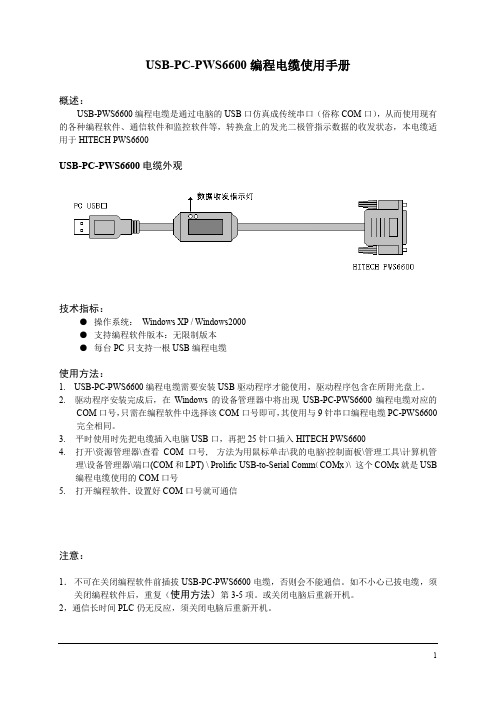
USB-PC-PWS6600编程电缆使用手册概述:USB-PWS6600编程电缆是通过电脑的USB口仿真成传统串口(俗称COM口),从而使用现有的各种编程软件、通信软件和监控软件等,转换盒上的发光二极管指示数据的收发状态,本电缆适用于HITECH PWS6600USB-PC-PWS6600电缆外观技术指标:●操作系统:Windows XP / Windows2000●支持编程软件版本:无限制版本●每台PC只支持一根USB编程电缆使用方法:1. USB-PC-PWS6600编程电缆需要安装USB驱动程序才能使用,驱动程序包含在所附光盘上。
2. 驱动程序安装完成后,在Windows的设备管理器中将出现USB-PC-PWS6600编程电缆对应的COM口号,只需在编程软件中选择该COM口号即可,其使用与9针串口编程电缆PC-PWS6600完全相同。
3.平时使用时先把电缆插入电脑USB口,再把25针口插入HITECH PWS66004.打开\资源管理器\查看COM口号, 方法为用鼠标单击\我的电脑\控制面板\管理工具\计算机管理\设备管理器\端口(COM和LPT) \ Prolific USB-to-Serial Comm(COMx)\ 这个COMx就是USB 编程电缆使用的COM口号5.打开编程软件, 设置好COM口号就可通信注意:1.不可在关闭编程软件前插拔USB-PC-PWS6600电缆,否则会不能通信。
如不小心已拔电缆,须关闭编程软件后,重复(使用方法)第3-5项。
或关闭电脑后重新开机。
2,通信长时间PLC仍无反应,须关闭电脑后重新开机。
USB-PC-PWS6600编程电缆驱动程序安装说明概述USB编程电缆是通过将电脑的USB口模拟成传统的串行口(通常为COM3),从而使编程软件通过USB-PC-PWS6600编程电缆与PWS6600系列进行通信。
功能●支持的操作系统Windows XP/ Windows2000●兼容USB V1.1 V2.0●波特率:300bps~1Mbps自动适应●每台PC只支持一根USB编程电缆系统要求请在使用USB编程电缆之前确认你的电脑是IBM PC兼容型并具备以下最低系统要求:●Intel兼容586DX4-100MHz中央处理器或更高●一个标准的USB接口(4-pin A型插座)驱动程序的安装驱动程序的安装非常简单,只需按提示进行即可,以Windows XP为例,按以下步骤进行:1、打开电脑主机,插入驱动程序光盘。
驱动程序详解及安装方法
驱动程序详解及安装方法想要熟知驱动安装方法首先要了解电脑硬件大概信息,了解了硬件信息安装就比较简单了,下面笔者为大家详解,首先我们了解驱动为何物。
一、什么是驱动程序根据百度百科:驱动程序,英文名为Device Driver,全称为设备驱动程序,是一种可以使计算机和设备通信的特殊程序,可以说相当于硬件的接口,操作系统只有通过这个接口,才能控制硬件设备的工作,假如某设备的驱动程序未能正确安装,便不能正常工作。
因此,驱动程序被誉为硬件的灵魂、硬件的主宰、和硬件和系统之间的桥梁等。
刚安装好的系统操作系统,很可能驱动程序安装得不完整。
硬件越新,这种可能性越大。
菜菜熊之前看到的图标很大且颜色难看就是没有安装好驱动的原因。
二、驱动程序的作用随着电子技术的飞速发展,电脑硬件的性能越来越强大。
驱动程序是直接工作在各种硬件设备上的软件,其驱动这个名称也十分形象的指明了它的功能。
正是通过驱动程序,各种硬件设备才能正常运行,达到既定的工作效果。
硬件如果缺少了驱动程序的驱动,那么本来性能非常强大的硬件就无法根据软件发出的指令进行工作,硬件就是空有一身本领都无从发挥,毫无用武之地。
这时候,电脑就正如古人所说的万事俱备,只欠东风,这东风的角色就落在了驱动程序身上。
如此看来,驱动程序在电脑使用上还真起着举足轻重的作用。
从理论上讲,所有的硬件设备都需要安装相应的驱动程序才能正常工作。
但像CPU、内存、主板、软驱、键盘、显示器等设备却并不需要安装驱动程序也可以正常工作,而显卡、声卡、网卡等却一定要安装驱动程序,否则便无法正常工作。
这是为什么呢?这主要是由于这些硬件对于一台个人电脑来说是必需的,所以早期的设计人员将这些硬件列为BIOS能直接支持的硬件。
换句话说,上述硬件安装后就可以被BIOS和操作系统直接支持,不再需要安装驱动程序。
从这个角度来说,BIOS也是一种驱动程序。
但是对于其他的硬件,例如:网卡,声卡,显卡等等却必须要安装驱动程序,不然这些硬件就无法正常工作。
安装和配置硬盘驱动器的步骤详解

安装和配置硬盘驱动器的步骤详解在本文中,将详细介绍安装和配置硬盘驱动器的步骤。
硬盘驱动器是计算机系统中存储数据的关键组件,正确地安装和配置硬盘驱动器对于计算机的正常运行至关重要。
下面将按照一般的安装流程,逐步介绍相关的步骤。
第一步:准备工作在安装和配置硬盘驱动器之前,有一些准备工作是必要的。
首先,确保计算机已经关机,并断开了电源。
其次,检查所需的材料是否齐全,包括硬盘驱动器、数据线、电源线等。
第二步:物理安装1. 打开计算机主机箱的侧面板,找到一个空的3.5英寸硬盘托架或硬盘位。
2. 将硬盘驱动器轻轻地滑入硬盘托架或硬盘位中,确保与数据和电源接口对齐。
3. 使用螺丝固定硬盘驱动器,以确保其稳固地安装在托架或位上。
4. 将硬盘驱动器的数据线插入主板上的SATA或IDE接口上,插头应与接口对齐。
同时,将硬盘驱动器的电源线插入电源供应器上的相应插槽。
第三步:BIOS设置1. 打开计算机,并按照提示进入BIOS设置界面(通常是按下Del、F2或F10键)。
2. 在BIOS设置界面中,找到"Boot"或"Advanced"选项,并选择"Boot Device Priority"或"Hard Disk Priority"。
3. 确保硬盘驱动器被设置为第一启动设备,以确保计算机能够从硬盘驱动器上加载操作系统。
4. 保存设置并退出BIOS。
第四步:操作系统安装与分区1. 使用操作系统安装光盘或USB启动盘启动计算机,并按照安装向导的指示进行操作系统的安装。
2. 在安装过程中,可以选择对硬盘驱动器进行分区和格式化。
这样可以更好地组织和管理存储在硬盘驱动器上的数据。
3. 按照向导的指示,选择适当的分区方案,并根据需要设置分区的大小。
4. 完成操作系统的安装后,计算机将重启。
第五步:驱动程序安装与更新1. 在操作系统安装完成后,需要安装硬盘驱动器的相关驱动程序,以保证其正常工作。
安装驱动器
11.2.6 安装驱动器安装驱动器主要包括硬盘、光驱和软驱的安装,它们的安装方法几乎相同。
1. 安装光盘驱动器下面先介绍安装光驱的操作步骤。
光盘驱动器也就包括CD-ROM、DVD-ROM和刻录机,其外观与安装方法都基本一样。
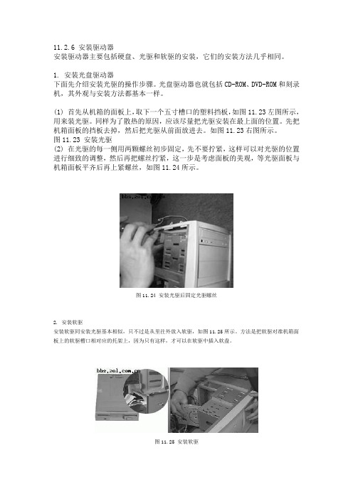
(1) 首先从机箱的面板上,取下一个五寸槽口的塑料挡板,如图11.23左图所示,用来装光驱。
同样为了散热的原因,应该尽量把光驱安装在最上面的位置。
先把机箱面板的挡板去掉,然后把光驱从前面放进去。
如图11.23右图所示。
图11.23 安装光驱(2) 在光驱的每一侧用两颗螺丝初步固定,先不要拧紧,这样可以对光驱的位置进行细致的调整,然后再把螺丝拧紧,这一步是考虑面板的美观,等光驱面板与机箱面板平齐后再上紧螺丝,如图11.24所示。
图11.24 安装光驱后固定光驱螺丝2. 安装软驱安装软驱同安装光驱基本相似,只不过是从里往外放入软驱,如图11.25所示。
方法是把软驱对准机箱面板上的软驱槽口相对应的托架上,因为只有这样,才可以在软驱中插入软盘。
图11.25 安装软驱接着再上好螺丝。
软驱固定好后最好拿个软盘来试一下可否顺利地插入、弹出,以确定是否到位。
3. 安装硬盘接下来安装硬盘,其安装的方法同安装光驱、软驱相同。
在这里需要注意的是,通常计算机的主板上只安装有两个IDE接口,而每条IDE数据线最多只能连接两个IDE硬盘或其他IDE设备,这样,一台计算机最多便可连接4个硬盘或其他IDE设备。
但是在PC机中,只可能用其中的一块硬盘来启动系统,因此如果连接了多块硬盘则必须将它们区分开来,为此硬盘上提供了一组跳线来设置硬盘的模式。
硬盘的这组跳线通常位于硬盘的电源接口和数据线接口之间,如图11.27左图所示。
跳线设置有3种模式,即是单机(Spare)、主动(Master)和从动(Slave)。
单机就是指在连接IDE硬盘之前,必须先通过跳线设置硬盘的模式。
如果数据线上只连接了一块硬盘,则需设置跳线为Spare模式;如果数据线上连接了两块硬盘,则必须分别将它们设置为Master和Slave模式,通常第一块硬盘,也就是用来启动系统的那块硬盘设置为Master模式,而另一块硬盘设置为Slave模式。
C141-E202-01EN 硬盘驱动器安装条件说明书

CHAPTER 3 Installation Conditions3.1 Dimensions3.2 MountingConnections3.3 CableSettings3.4 JumperThis chapter gives the external dimensions, installation conditions, surfacetemperature conditions, cable connections, and switch settings of the hard diskdrives.For information about handling this hard disk drive and the system installationprocedure, refer to the following Integration Guide.C141-E144Installation Conditions3.1 DimensionsFigure 3.1 illustrates the dimensions of the disk drive and positions of themounting screw holes. All dimensions are in mm.Figure 3.1 Dimensions3.2 Mounting3.2 MountingFor information on mounting, see the "FUJITSU 2.5-INCH HDD INTEGRATION GUIDANCE (C141-E144)."(1) OrientationFigure 3.2 illustrates the allowable orientations for the disk drive.(a) Horizontal –1(b) Horizontal –1(c) Vertical –1(d) Vertical –2(e) Vertical –3(f) Vertical –4Figure 3.2 OrientationgravitygravitygravityInstallation Conditions(2) FrameThe MR head bias of the HDD disk enclosure (DE) is zero. The mounting frame is connected to SG.IMPORTANTUse M3 screw for the mounting screw and the screw length should satisfy the specification in Figure 3.3.The tightening torque must be 0.49N •m (5kgf•cm).m (5kgf•cm).When attaching the HDD to the system frame, do not allow the system frame to touch parts (cover and base) other than parts to which the HDD is attached.(3) Limitation of mountingNote) These dimensions are recommended values; if it is not possible to satisfythem, contact us.Figure 3.3 Mounting frame structureScrewScrewDetails of BDetails of A3.0 or less3.0 or lessFrame of system cabinetFrame of system cabinetBPCAA22.52.52.52.5DESide surface mountingBottom surface mounting3.2 MountingIMPORTANTBecause of breather hole mounted to the HDD, do not allow this toclose during mounting.Locating of breather hole is shown as Figure 3.4.For breather hole of Figure 3.4, at least, do not allow its aroundφ 2.4 to block.Figure 3.4 Location of breatherInstallation Conditions(4) Ambient temperatureThe temperature conditions for a disk drive mounted in a cabinet refer to theambient temperature at a point 3 cm from the disk drive. The ambienttemperature must satisfy the temperature conditions described in Section 1.4, andthe airflow must be considered to prevent the DE surface temperature fromexceeding 60 °C.Provide air circulation in the cabinet such that the PCA side, in particular,receives sufficient cooling. To check the cooling efficiency, measure the surfacetemperatures of the DE. Regardless of the ambient temperature, this surfacetemperature must meet the standards listed in Table 3.1. Figure 3.5 shows thetemperature measurement point.•Figure 3.5 Surface temperature measurement pointsTable 3.1 Surface temperature measurement points and standard valuespoint Temperature No. Measurement1 DE cover 60 °C max3.2 Mounting(5) Service areaFigure 3.6 shows how the drive must be accessed (service areas) during and afterinstallation.Mounting screw holeCable connectionMounting screw holeFigure 3.6 Service areaData corruption: Avoid mounting the disk drive near strongmagnetic sources such as loud speakers. Ensure that the disk driveis not affected by external magnetic fields.Damage: Do not press the cover of the disk drive. Pressing it toohard, the cover and the spindle motor contact, which may causedamage to the disk drive.Static: When handling the device, disconnect the body ground(500 kΩ or greater). Do not touch the printed circuit board, buthold it by the edges.(6) Handling cautionsPlease keep the following cautions, and handle the HDD under the safetyenvironment.Installation Conditions-General notesFigure 3.7 Handling cautions- Installation(1) Please use the driver of a low impact when you use an electric driver.HDD is occasionally damaged by the impact of the driver. (2)Please observe the tightening torque of the screw strictly.M3 ······· 0.49N ·m (5 kgf ·cm). -Recommended equipmentsContents Model Maker Wrist strap JX-1200-3056-8 SUMITOMO 3M ESD ESD mat SKY-8A (Color Seiden Mat) Achilles ShockLow shock driver SS-6500 HIOSPlace the shock absorbing mat on the operation table, and place ESD mat on it. Use the Wrist strap.Do not hit HDD each other.Do not stack when carrying.Do not place HDD verticallyto avoid falling down. Do not drop.Shock absorbing matESD matWrist strap3.3 Cable Connections 3.3 Cable Connections3.3.1 Device connectorThe disk drive has the connectors and terminals listed below for connectingexternal devices. Figure 3.8 shows the locations of these connectors andterminals.PCAFigure 3.8 Connector locationsInstallation Conditions3.3.2 Cable connector specificationsTable 3.2 lists the recommended specifications for the cable connectors.Table 3.2 Cable connector specificationsNameModelManufacturerATA interface and power supply cable (44-pin type) Cable socket(44-pin type)89361-144 FCI IMPORTANTFor the host interface cable, use a ribbon cable. A twisted cable or acable with wires that have become separated from the ribbon maycause crosstalk between signal lines. This is because the interface isdesigned for ribbon cables and not for cables carrying differentialsignals.3.3.3 Device connectionFigure 3.9 shows how to connect the devices.Figure 3.9 Cable connections3.3.4 Power supply connector (CN1)Figure 3.10 shows the pin assignment of the power supply connector (CN1).Figure 3.10 Power supply connector pins (CN1)3.4 Jumper Settings3.4.1 Location of setting jumpersFigure 3.11 shows the location of the jumpers to select drive configuration andfunctions.Figure 3.11 Jumper location3.4.2 Factory default settingFigure 3.12 shows the default setting position at the factory.Figure 3.12 Factory default setting3.4.3 Master drive-slave drive settingMaster drive (disk drive #0) or slave drive (disk drive #1) is selected.(b) Slave drive(a) Master driveOpenFigure 3.13 Jumper setting of master or slave driveNote:Pins A and C should be open.3.4.4 CSEL settingFigure 3.14 shows the cable select (CSEL) setting.ShortNote:The CSEL setting is not depended on setting between pins Band D.Figure 3.14 CSEL settingFigure 3.15 and 3.16 show examples of cable selection using unique interfacecables.By connecting the CSEL of the master drive to the CSEL Line (conducer) of thecable and connecting it to ground further, the CSEL is set to low level. The driveis identified as a master drive. At this time, the CSEL of the slave drive does nothave a conductor. Thus, since the slave drive is not connected to the CSELconductor, the CSEL is set to high level. The drive is identified as a slave drive.Figure 3.15 Example (1) of Cable SelectFigure 3.16 Example (2) of Cable Select3.4.5 Power Up in Standby settingWhen pin C is grounded, the drive does not spin up at power on.。
硬盘电源线接法图解

硬盘电源线接法图解主板上有专门的硬盘接口,用硬盘或者主板带的数据线连接,注意有方向性。
机箱电源上有很多电源线插头,选择合适的接口插入硬盘后面的对应规格接口,也有方向的。
机箱电源线大多数接口相似,是联硬盘光驱的,独特的大口,接主板上供电。
如不会,可找个DIY 组装电脑的书看,版本要新些的。
或者找视频看。
实在不行就找会的可靠的人帮忙。
注意一定要先拔下电脑主机和交流电市电连接的电源线。
光关闭电脑主机开关不行。
左边是并口硬盘的接法,右边是串口硬盘的接法新的SATA串口的硬盘和光驱采用了新式的电源接口,找找电源出来的线应该有比较宽的,一般为黑色的很扁的插头,把那个插头接到光驱和硬盘相对应的口上就行了。
一、初识SATA硬盘SATA硬盘与PATA硬盘从外观上粗看是差不多的,它们最主要的区别在连接线上。
两块不同接口的硬盘放在了一起(如图1),图1首先让我们来看一看它们的信号线,以往的PATA硬盘采用的是40或80针的扁平硬盘线作为传输数据的通道,而SATA接口的硬盘采用的是七芯的数据线,采用点对点的传输协议,仅使用两根数据线进行信号传送,这样就不会受到机箱内各种频率的干扰,使硬盘缓存中的数据可以顺畅无阻的传送至内存中进行处理,而它的传输速度在设计时就比PATA硬盘快,所以SATA接口的硬盘在速度上要比普通PATA硬盘有所提高。
SATA信号线除抗干扰外,它还比PATA数据线轻薄很多。
SATA 信号线的宽度仅为1厘米多一点,而长度却可达1米,而传统的PATA 硬盘信号线则宽达4.5厘米,长度又不能超过40厘米(如图2)。
图2在电源线上SATA与PATA硬盘也各不相同。
这是因为SATA硬盘需要3.3V、5V和12V等多种电压,几种不同电压加起来就需要输入电源线要有15个针脚了。
而我们以前使用的PATA硬盘采用是D型4针电源接口,而由于在一些旧电源上并没有为SATA硬盘提供专门的电源线插头,所以很多SATA硬盘除了SATA硬盘的专用电源接口之外,还提供了传统PATA硬盘使用的D型4针电源接口(如图3)。
IBM SATA 接口硬盘驱动器安装指南说明书

NL35.2 Series Serial ATA Installation GuideST3400833NS, ST3400633NS, ST3250824NS and ST3250624NS Serial ATA (SATA) Interface Disc DrivesPublication Number: 100409438, Rev. A, September 2006Serial ATA (SATA) interface disc drives are designed for easy installation. It is normally not necessary to set any jumpers, terminators, or other settings on this drive for proper operation.With a SATA interface, each disc drive has its own cable that connects directly to a SATA host adapter or a SATA port on your motherboard. Unlike Parallel ATA, there is no master-slave relationship between drives that use a SATA interface.You can use a SATA drive in the same system with Parallel ATA drives as long as both interfaces are supported on the motherboard or with a host adapter. This makes it easy to add SATA capability to your existing system without removing existing Parallel ATA disc drives.What you need• A Phillips screwdriver and four 6-32 UNC drive mounting screws.• A SATA interface cable (sold separately). Maximum length is 39 inches(1 meter).• A SATA-compatible power cable or adapter (sold separately).• A system with a SATA connector on it, or a SATA host adapter and avail-able PCI slot in which to install the adapter.Refer to your computer system documentation to see if your system sup-ports SATA on the motherboard and locate the SATA connector. If your system does not have a SATA connector on the motherboard, you must purchase a SATA host adapter that is compatible with your computer and operating system and install it with the appropriate device driver according to the host adapter manufacturer’s installation instructions.Note.See /support/disc/sata/ for a list of companies that sell SATA components.Handling precautions/electrostatic discharge protection •Disc drives are fragile. Do not drop or jar the drive. Handle the drive only by the edges or frame.•Drive electronics are extremely sensitive to static electricity. While installing the drive, wear a wrist strap and cable connected to ground.•Turn off the power to the host system during installation.•Do not disassemble the drive. Doing so voids the warranty. See the Warranty information on page 2.•Do not apply pressure or attach labels to the circuit board or to the top of the drive.The easiest way to install your drive in a Windows systemTo successfully install and obtain the maximum capacity from the drive, use DiscWizard for Windows disc drive installation software utility. This util-ity is available exclusively from Seagate. You can download this free disc drive installation software from our web site at /support or run the program directly from your web browser.Note.Older versions of DiscWizard do not recognize Serial ATA model numbers. Make sure that you use DiscWizard for Windows or later when installing a NL35.2 Series® Serial ATA disc drive.To run DiscWizard:Follow the instructions on the download page at to cre-ate a diskette and complete the installation.If you cannot run DiscWizard, follow the instructions on this installation sheet to install and configure your drive.Breather filter hole precautionCaution.Do not cover, seal, or insert any object into this hole. If this hole is covered, sealed, or penetrated by any object, the drive reliabil-ity may be compromised and could lead to permanent damageand voids the warranty.Attaching cables and mounting the drive1.Attach one end of the drive interface cable to the SATA interface con-nector on your computer’s motherboard or SATA host adapter (see your computer manual for connector locations).Note.Serial ATA connectors are keyed to ensure correct orientation.2.Attach the interface and power cables to the drive.3.Secure the drive using four 6-32 UNC mounting screws in either theside-mounting or bottom-mounting holes. Insert the screws no more than 0.20 inches (5.08 mm) into the bottom-mounting holes and no more than 0.14 inches (3.55 mm) into the side-mounting holes. Note.Do not overtighten the screws or use metric screws. This may dam-age the drive.Configuring the BIOSClose your computer case and restart your computer. Your computer may automatically detect your new drive. If your computer does not automati-cally detect your new drive, follow the steps below.1.Restart your computer. While the computer restarts, run the systemsetup program (sometimes called BIOS or CMOS setup). This is usu-ally done by pressing a special key, such as DELETE, ESC, or F1 dur-ing the startup process. See your system documentation for details about your particular system.2.Within the system setup program, instruct the system to auto detectyour new drive.3.Save the settings and exit the setup program.When your computer restarts, it should recognize your new drive. If your system still doesn’t recognize your new drive, see the troubleshooting sec-tion on the back of this sheet.Note.Some systems may see the drive and classify it as a SCSI device.This is normal even though this is not a SCSI disc drive. This does not affect performance or capacity.Microsoft operating system installation instructionsFor detailed information about installing a Microsoft operating system on your new Seagate drive, refer to the Microsoft Knowledgebase Article ref-erences below. To locate an article, go to andenter the article number in any search box on the Microsoft web site. Forexample, to view the Knowledgebase article for installing Windows XP on your new Seagate drive:1.Open your browser and go to .2.Enter 313348 in the Microsoft web site’s search box, and then pressEnter. Locate and select the most accurate options from the search results. The article is displayed on your screen.Installing the drive in Mac OS X systems1.I nstall the drive in your system using the instructions provided on thefront of this installation guide.2.Insert the Mac OS X Install CD 1 (OS 10.3 and earlier) or Install DVD(OS 10.4). These operating system discs are provided by Apple and nor-mally ship with Apple computers.3.Restart the computer while holding the C key (you can release the C keyafter you see the Apple logo appear on the screen). In Mac OS X 10.4 or later, you must select your language after booting from these install discs.4.If the new drive you just installed is the only disc in your system (replac-ing the original hard disc drive), click on “continue” and follow the on-screen instructions to install OS X on your new drive. If the new drive you installed is not the only drive in your system, do not click on ‘continue.’Instead, select Disk Utility from the Utilities menu located in the top menu area.5.Select the drive you want to install in the left panel.Warning.Be sure to select the correct disc before erasing the drive. Just as the name implies, erasing erases all data on the selected drive. Note.If you are installing the drive in an Apple G5 system and the system does not recognize the drive, contact Seagate Technical Support using the phone number for your region listed in the “Seagate support services” section in this installation guide for information about com-patibility with Apple G5 systems.6.Click on Erase and then select a volume format (Mac OS Extended is acommonly-used format), type a name of your choice in the Name field, and click on Erase again. Confirm your intentions by clicking Erase once more to begin formatting the drive.Macintosh TroubleshootingSee for Macintosh troubleshooting information.Windows TroubleshootingIf your drive is not working properly, these troubleshooting tips may help solve the problem.1.Does the drive spin up? A spinning drive produces a faint whine andclicking noise. If your drive does not spin, check that the power connec-tor and interface cable are securely attached.2.Does the computer recognize the drive? Verify that the drive isenabled in the system CMOS or setup program. If not, select the autode-tect option and enable it. If your drive has a problem, it may not be rec-ognized by the system. If the operating system does not recognize the drive, you need to load your host adapter drivers.3.I receive a “drive not detected” message. Why? Your SATA-equippedmotherboard or host adapter may use a chipset that does not support SATA speed autonegotiation or other 3 Gbit feature. Install a jumper as shown in the following illustration to limit the data transfer rate to 1.5 Gbits per second and enhance compatibility with some computers.4.Does Scandisk find the drive defect-free? Scandisk is a utility locatedon your Windows startup diskette that scans the drive for defects. Ifdefects are detected, this may be an indication of a problem.5.Why does my computer hang on startup? Verify that your system isSATA compatible. You need either a SATA 1.0-compatible motherboard connector or Serial ATA host adapter to use this drive.6.I’m running Windows 98 and FDISK is not reporting the full capacityof my drive. Why? You need to upgrade your version of FDISK if you are using the diskettes or CD that came with your original Windows 95 or98 operating system. Microsoft provides a free downloadable FDISKupgrade. See Microsoft Knowledgebase article number 263044 located at .Note.If these tips do not answer your question or solve the problem, con-tact your dealer or visit to download SeaTools disc diagnostics software and more troubleshooting advice. Seagate support servicesFor online information about Seagate products, visit or ************************************************.I f you need help installing your drive, consult your dealer first. I f you need additional help, call a Seagate technical support specialist. Before calling, note your system configuration and drive model number.Africa+1-405-324-4714Netherlands00 800-47324283 Australia1800-14-7201New Zealand0800-443988 Belgium00 800-47324283Norway00 800-47324283 China*800-810-9668Poland00 800-311 12 38 Denmark00 800-47324283Spain00 800-47324283 France00 800-47324283Sweden00 800-47324283 Germany00 800-47324283Switzerland00 800-47324283 Hong Kong800-90-0474Singapore800-1101-150Hong Kong†001-800-0830-1730Taiwan*00-800-0830-1730 India1-800-180-1104Thailand001-800-11-0032165 Indonesia001-803-1-003-2165Turkey00 800-31 92 91 40 Ireland00 800-47324283United Kingdom00 800-47324283 Italy00 800-47324283USA/Canada/1-800 SEAGATE or Japan0034 800 400 554Latin America+1-405-324-4700 Korea007 98 8521 7635Other EuropeanMalaysia1-800-80-2335countries+1-405-324-4714 Middle East+1-405-324-4714*Mandarin†CantoneseWarranty.To determine the warranty status of your Seagate disc drive, contact your place of purchase or visit our web site at for more information. Return Merchandise Authorization (RMA).Run SeaTools to diagnose your drive before requesting a return authorization. In addition, please verify that your drive is defective by following the troubleshooting checklist in this guide. Seagate offers com-prehensive customer support for all Seagate drives worldwide. Seagate customer ser-vice centers are the only facilities authorized to service Seagate drives. Drive return procedures vary depending on geographical location and are subject to current interna-tional trade regulations.Shipping the driveCaution.Back up the data before shipping. Seagate assumes no responsibility for data lost during shipping or service.Shipping drive in an unapproved container voids the warranty. Pack the drive with origi-nal box and packing materials. Use no other materials. This prevents electrical and physical damage in transit.Electromagnetic compliance for the European Union. This model complies with the European Union requirements of the Electromagnetic Compatibility Directive 89/336/ EEC of 03 May 1989 as amended by Directive 92/31/EEC of 28 April 1992 and Directive 93/68/EEC of 22 July 1993. Compliance of this drive, as a system component, was con-firmed with a test system. We cannot guarantee that your system will comply. The drive is not meant for external use (without enclosure, shielded I/O cable, etc.). Sicherheitsanleitung1. Das Gerrät ist ein Einbaugerät, das für eine maximale Umge-bungstempeatur von 60°C vorgesehen ist. 2. Zur Befestigung des Lufwerks werden 4 Schrauben 6-32 UNC-2A benötigt. Bei seitlicher Befestigung darf die maximale Länge der Schrauben im Chassis nicht merh als 3,3 mm und bei Befestigung an der Unterseite nicht mehr als 5,08 mm betragen. 3. Als Versorgungsspannugen werden benötigt: +12V +/- 5% 2,9A 4. Die Versorgungsspannung muss SELV entsprechen. 5. Alle Arbeiten auf dem Festplattte dürfen nur von Ausgebiletem Serciepersonal durchgeführt werden. Bitte entfernen Sie nicht die Aufschriftenschilder des Laufwerkes. 6. Der Einbau des Lauf-werkes muss den Anforderungen gemäss DIN IEC 950 VDE 0805/05.90 entspreche.©2006 Seagate Technology LLC. All rights reservedPublication number: 100409438, Rev. A, September 2006, Printed in USASeagate, Seagate Technology, and the Wave logo are registered trademarks of Seagate Technology LLC. NL35 Series and DiscWizard are registered trademarks or trademarks of Seagate Technology LLC. Other product names are registered trade-marks or trademarks of their owners. One gigabyte, or Gbyte, equals one billion bytes when referring to hard drive capacity. Accessible capacity may vary depending on oper-ating environment and formatting. Seagate reserves the right to change, without notice, product offerings or specifications.Operating system Microsoft knowledgebase article numbersWindows XP313348. See also: 316941 Windows 2000/NT308209. See also: 175761。
安装SATA硬盘图解
安装SATA硬盘图解随着i915/945等新一代主板芯片组推出后,硬盘的连接界面也从沿用多年的Parallel ATA(并行ATA,以下简称PATA)界面,逐渐转变为设计更先进、速度更快的Serial ATA(串行ATA,以下简称SATA)界面。
不过,由于SATA界面的外设在现阶段仍然属于是一种比较新的硬件,因此在安装时若不留神就会遇到困难。
为此,在这里与大家探讨一下有关安装SATA硬盘的知识技巧。
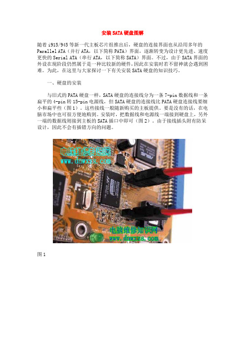
一、硬盘的安装与旧式的PATA硬盘一样,SATA硬盘的连接线分为一条7-pin数据线和一条扁平的4-pin转15-pin电源线,但SATA硬盘的连接线比PATA硬盘连接线要细小和扁平些(图1)。
这些接线一般随新购买的主板提供。
要是没有的话,在电脑市场中也可很方便地购到。
安装时,把数据线和电源线一端接到硬盘上,另外一端的数据线则接到主板的SATA插口中即可(图2)。
由于接线插头附有防呆设计,因此不会有插错方向的问题。
图1图2但有一点要注意的是,如果用户需要在系统通电状态下以Hot-Plug(热插拨)方式安装SATA硬盘,必须先装好4-pin转15-pin电源线,并把15-pin插头接到硬盘后,再接上数据线,否则会烧毁硬盘的电路。
二、主板BIOS的设置目前,主板支持SATA界面一般借助于两种方式,即主板上南桥芯片已经内置SATA功能和单独的RAID/Serial ATA控制芯片。
前者通过主板南桥芯片(如Intel的ICH5/6南桥芯片)来实现,故需在主板BIOS中对IDE模式进行设置。
按主板的不同,BIOS中有一项名为“IDE Configuration”或“On-Chip SATA Mode”的设置项目,一般提供AUTO/Combined/Enhanced及Non-Com-bined等4种模式,其意义解释如下:--------------------------------------------------------模式效果AUTO 让BIOS自动检测Combined 最多同时使用2个SATA及2个PATA设备Enhanced 最多同时使用6个设备,包括SATA及PATA设备Non-Combined 将SATA设备自动模拟成PATA模式工作--------------------------------------------------------在多数情况下,选择“Enhanced”模式可获得最佳的性能和扩展性,但对于老版本操作系统及部分DOS模式下运行的软件(如旧版GHOST)等,却有可能出现兼容问题。
LaCie 移动驱动器 高速 USB 2.0 说明书

目录健康与安全注意事项 3使用注意事项 31. LaCie 移动硬盘驱动器简介5 1.1. 最小系统要求 61.2. 包装内容62. 进行连接7 2.1. Silverlining 98 和 USB 2.0 驱动程序安装8 2.2.连接 USB 2.0 接口电缆92.3.连接 USB 电源线103. 使用 LaCie 驱动器 11 3.1. 对 LaCie USB 移动硬盘驱动器进行格式化和分区12 3.2. 高速 USB 2.0 连接 163.3. 断开 LaCie 移动硬盘驱动器184. 故障排除19 4.1. Mac 用户194.2. Windows 用户215. 联系客户支持部门235.1. LaCie 技术支持部门联系方式246. 担保信息25版权版权所有©2006LaCie。
保留所有权利。
未经LaCie书面许可,不得对此出版物的任何部分进行复制、存储于检索系统,或以其它任何形式或方式进行传播,包括以电 子、机械、影印、录音或其它方式。
商标Apple、Mac和Macintosh是Apple Computer,Inc.的注册商标。
Microsoft、Windows98、Windows 98SE、Windows2000、Windows Millennium Edition和Windows XP 是Microsoft Corporation的注册商标。
本手册中涉及的其它商标均为其各自所有者的资产。
变更本文档中的材料仅供参考,如有变更,恕不另行通知。
虽然我们已对本文档内容进行了详尽校对,并力求准确,但是,如仍有错误或疏漏,或由于使用此处提供的信息而造成损失,LaCie不承担任何责任。
LaCie保留随时更改或修改产品设计或产品手册而无需预先通知任何人的权利。
加拿大符合性声明此A类数字设备符合加拿大有关引起干扰的设备规定的所有要求。
FCC声明本设备符合FCC规则第15部分的规定。
设备的运行需符合以下条件:本设备不会产生有害干扰。
看如何正确安装电脑驱动程序

看如何正确安装电脑驱动程序电脑驱动程序是操作系统与硬件设备之间的桥梁,它能够确保硬件设备和操作系统之间的正常通信和协作。
正确安装电脑驱动程序对于电脑的正常运行非常重要。
本文将详细介绍如何正确安装电脑驱动程序。
一、了解电脑驱动程序在开始介绍如何正确安装电脑驱动程序之前,我们首先需要了解一些与电脑驱动程序相关的知识。
电脑驱动程序通常由设备厂商提供,用于使操作系统能够正常识别和控制硬件设备。
常见的电脑硬件设备包括显卡、声卡、网卡、打印机等。
每一种硬件设备都对应着一个特定的驱动程序。
驱动程序的作用是使操作系统能够正确识别硬件设备,并通过与硬件设备的通信接口,实现对硬件设备的控制和管理。
二、寻找适合的电脑驱动程序在安装电脑驱动程序之前,我们首先需要确定电脑所配备的硬件设备型号和厂商信息。
这些信息通常可以在硬件设备上的标识或者设备管理器中找到。
设备管理器是Windows操作系统中的一个重要工具,可以用来查看和管理计算机的硬件设备。
打开设备管理器后,我们可以找到需要安装驱动程序的硬件设备,并获取其详细信息。
根据硬件设备的型号和厂商信息,我们可以在设备厂商的官方网站或者其他可靠的驱动程序下载网站上寻找相应的驱动程序。
在下载驱动程序时,务必注意选择与操作系统和硬件设备型号完全兼容的驱动程序。
三、安装电脑驱动程序安装电脑驱动程序的具体步骤如下:1. 下载驱动程序:将电脑连接到互联网后,打开设备厂商的官方网站或者其他可靠的驱动程序下载网站,找到与硬件设备型号和操作系统完全兼容的驱动程序,并下载到本地。
2. 解压驱动程序:若下载的驱动程序是一个压缩文件,需使用解压软件对其进行解压,以获取其中的安装文件。
3. 安装驱动程序:双击打开解压后的安装文件,根据提示点击“下一步”进行安装。
在安装过程中,可能会弹出一些特定于驱动程序的设置选项,用户可根据需要进行选择或调整。
4. 重启电脑:在安装完成后,有些驱动程序可能需要重启电脑才能生效。
同友存储iSUM450G2_快速安装指南
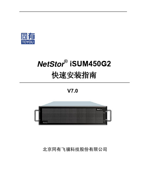
V7.0
北京同有飞骥科技股份有限公司
NetStor® iSUM450G2 快速安装指南
文档修订记录
版本号 V1.0 V7.0
日期 2010-10-18 2011-01-24
描述说明 首发版 公司名称变更,产品工程统一切换
-2-
声明
北京同有飞骥科技股份有限公司 2011 年版权所有。 如未事先得到北京同有飞骥科技股份有限公司的任何书面许可,手册中任何
2
NetStor® iSUM450G2 快速安装指南
对于本手册列出的安全使用注意事项,必须仔细理解并在磁盘阵列使用 过程中严格执行,这将有助于更好地使用和维护磁盘阵列。 1. 仔细阅读随机光盘提供的资料,了解磁盘阵列的使用方法和注意事项。 2. 检查磁盘阵列的实际配置与装箱单是否一致,如有异议马上与经销商联系。 3. 您使用的 iSUM450G2 磁盘阵列采用支持 110/220V 自适应电源供电系统。 4. 一定要使用带接地保护的三芯电源插头和插座,良好的接地是磁盘阵列正
1.3 安全规范要求 ...................................................................................................... 2
第 2 章 导 引............................................................................................................... 5 第 3 章 安装步骤........................................................................................................... 6
如何正确安装电脑硬件驱动

如何正确安装电脑硬件驱动在使用电脑的过程中,有时我们需要安装新的硬件驱动程序来确保设备能够正常运行和发挥最佳性能。
然而,对于一些用户来说,安装硬件驱动可能会有些困扰,特别是对于那些不太熟悉电脑操作的人来说。
本文将为大家详细介绍如何正确安装电脑硬件驱动,让你轻松搞定这个问题。
步骤一:准备工作在安装硬件驱动之前,我们需要做一些准备工作。
确保你已经下载了最新版本的硬件驱动程序,可以从设备制造商的官方网站上获取。
检查一下你的设备管理器,看看是否有黄色感叹号的设备,这些设备表示缺少驱动程序或者存在问题。
步骤二:安装硬件驱动右键点击“此电脑”或“我的电脑”,选择“管理”。
在电脑管理窗口中,点击“设备管理器”。
找到你要安装驱动的硬件设备,右键点击该设备,选择“更新驱动程序”。
选择“自动搜索更新的驱动程序”,让系统自动搜索并安装最新的驱动程序。
如果系统没有找到适合的驱动程序,你可以手动安装。
在硬件制造商提供的驱动程序文件夹中找到适合你操作系统的驱动程序,右击选择“安装”。
完成安装后,重启电脑,确保驱动程序已经成功安装。
步骤三:注意事项在安装驱动程序时,最好断开互联网连接,避免系统自动更新驱动程序版本,导致冲突。
定期更新硬件驱动程序有助于提升系统性能和稳定性,建议每个月检查更新一次。
如果遇到安装问题,可以在硬件制造商的官方网站上查找帮助文档或者寻求技术支持。
现在,你已经了解了如何正确安装电脑硬件驱动了吧?希望这些简单的步骤能够帮助你轻松解决安装驱动程序的问题,让你的电脑设备保持最佳状态!学会正确安装电脑硬件驱动是电脑用户的基本技能之一,通过简单的几个步骤,你可以轻松完成这项任务,保证设备不出现问题,并获得更好的使用体验。
不断学习和提升操作技能,让电脑工作更高效更稳定。
图解光驱跳线的接法+硬盘跳线的接法+原理
图解光驱跳线的接法硬盘跳线的接法原理图解光驱跳线的接法硬盘跳线的接法原理光驱跳线设置图解光驱在出厂后默认被设为从盘。
光驱跳线与硬盘跳线很类似,其跳线位置多在光驱后面,数据线接口和电源线接口之间。
一般只有Master(主盘)、Slave(从盘)、CableSelect(线缆选择)三种,很少有其他情况,各个品牌的光驱几乎都是这样,相对来说很规范,使得设置比较简单。
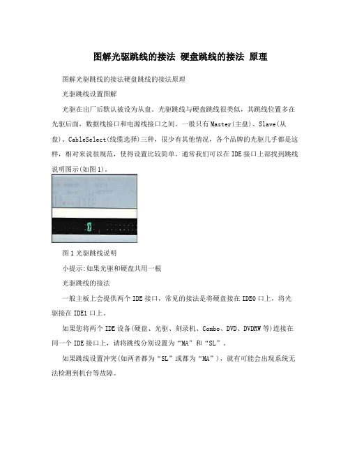
通常我们可以在IDE接口上部找到跳线说明图示(如图1)。
图1光驱跳线说明小提示:如果光驱和硬盘共用一根光驱跳线的接法一般主板上会提供两个IDE接口,常见的接法是将硬盘接在IDE0口上,将光驱接在IDE1口上。
如果您将两个IDE设备(硬盘、光驱、刻录机、Combo、DVD、DVDRW等)连接在同一个IDE接口上,请将跳线分别设置为“MA”和“SL”。
如果跳线设置冲突(如两者都为“SL”或都为“MA”),就有可能会出现系统无法检测到机台等故障。
设置光驱跳线的方法为:在光驱的后面板上有一个3×2六个针脚的接口,在接口的上方对应每一列都有竖排的英文字母标识,如果想设置该设备为“MASTER”,只需给对应字母“MA”的下方两个针脚戴上跳线帽即可。
同理如欲设置该设备为“SLAVE”,只需将跳线帽戴到对应字母“SL”的下方两个针脚上即可。
屏蔽光驱1.最简单直接有效的办法,拔光驱线。
2. 在BIOS中正确屏蔽光驱(以下部分为引用):由于工作上的需要,单位决定对未授权用户禁用所有的光驱和软驱。
要解决这个问题,笔者首先想到的是使用超级兔子魔法设置软件,用该软件可以隐藏光驱和软驱,虽然在资源管理器中不能直接看到光驱和软驱,但在资源管理器或IE的地址栏输入软驱和光驱的盘符,光驱和软驱还是乖乖地显示出来,照样可以正常访问。
于是想到从BIOS中屏蔽掉光驱和软驱,再设置好访问BIOS的口令,防止别人修改BIOS参数,就可以禁用光驱和软驱了。
开机按DEL进入BIOS设置,将软驱和光驱都设置成None开机自检后,虽然软驱被屏蔽掉,但光驱仍然能够自检到,并且进入Windows,仍然可对光驱进行读写操作。
USB编程电缆驱动程序安装指南详细说明书
USB编程电缆驱动程序安装说明概述USB编程电缆是通过将电脑的USB接口模拟成传统的串行口(通常为COM3),从而使用现有的编程软件或通信软件,通过编程电缆与PLC等设备的传统接口进行通信。
功能●支持的操作系统Windows2000/Windows XP●完全兼容USB V1.1和USB CDC V1.1规范●USB总线供电(非隔离电缆)、或USB总线供电与PLC的编程口同时供电(隔离型电缆)●波特率:300bps~1Mbps自动适应●每台PC只支持一根USB编程电缆系统要求请在使用USB编程电缆之前确认你的电脑是IBM PC兼容型并具备以下最低系统要求:●Intel兼容586DX4-100MHz中央处理器或更高●一个标准的USB接口(4-pin A型插座)●运行操作系统为Windows2000或Windows XP驱动程序的安装驱动程序的安装非常简单,只需按提示进行即可,以Windows XP为例,按以下步骤进行:1、打开将要连接USB编程电缆的电脑电源,并确认电脑的USB口已经启动并正常工作。
2、将USB编程电缆插入电脑的USB接口,Windows将检测到设备并运行添加新硬件向导帮助你设置新设备,插入驱动程序光盘并单击下一步继续。
如果Windows没有提示找到新硬件,那么在设备管理器的硬件列表中,展开“通用串行总线控制器”,选择带问号的USB设备,单击鼠标右键并运行更新驱动程序。
3、Windows将检测到安装信息,显示“ USB High Speed Serial Converter ”设备,并出现如下没有通过Windows徽标测试的信息框,单击“仍然继续”。
4、继续安装,让Windows拷贝驱动程序文件到你的硬盘。
5、当Windows显示完成找到新硬件向导,单击“完成”结束安装。
6、安装完成后,请确认在Windows的“开始\设置\控制面板\系统\硬件\设备管理器”菜单的“端口(COM和LPT)”展开条目中出现“ USB Serial Port(COMx)”,这个COMx就是USB编程电缆使用的COM口号。
固态硬盘识别为外接磁盘的解决方法

固态硬盘识别为外接磁盘的解决方法1.引言1.1 概述概述:随着技术的不断发展,固态硬盘(SSD)作为一种新型的存储设备,其速度快、耐用性好等特点使得其备受瞩目。
然而,有时候我们连接固态硬盘时,却发现其被识别为外接磁盘的情况。
这种情况对于用户来说显然是不正常的,因为我们期望固态硬盘能够被识别为固态硬盘,并且能够正常使用。
为了解决这一问题,本文将介绍固态硬盘识别为外接磁盘的原因,并提供一些有效的解决方法。
在正文部分,我们将首先描述该问题的具体表现和可能的原因。
然后,我们将介绍一系列解决方法,包括硬件和软件方面的调整以及操作系统的设置优化。
通过这些解决方法,我们希望读者能够正常地识别固态硬盘,并且享受到其高速和稳定性所带来的优势。
最后,在结论部分,我们将对本文所提供的解决方法进行总结,并对未来固态硬盘识别问题的解决方向进行展望。
固态硬盘作为新兴的存储设备,其市场份额将不断增加。
因此,解决固态硬盘识别问题的研究和探索具有重要的现实意义。
希望本文能够为读者理解和解决这一问题提供有用的参考和指导。
1.2文章结构1.2 文章结构本文将按照以下结构进行阐述固态硬盘被识别为外接磁盘的解决方法:1. 引言:对固态硬盘被识别为外接磁盘的问题进行概述,并说明本文的目的。
2. 正文:2.1 问题描述:详细描述固态硬盘被错误地识别为外接磁盘的现象,包括其可能的原因和对计算机系统造成的影响。
同时,给出一些常见的外接磁盘的特征,以便更好地区分固态硬盘和外接磁盘。
2.2 解决方法:介绍一些常见的解决方法,包括通过更改设备驱动程序、设置BIOS选项以及进行硬件连接的调整等方法。
每种方法都将详细说明其操作步骤和注意事项,并给出相应的操作示例。
同时,对于不同操作系统和计算机品牌的用户,提供适用的解决方案。
3. 结论:3.1 总结:对本文所介绍的固态硬盘识别为外接磁盘的解决方法进行总结,强调其实用性和可行性。
同时,列举一些使用解决方法后,固态硬盘被正确识别的案例,说明解决方法的有效性。
硬盘驱动器安装指南

硬盘驱动器安装指南在现代的计算机时代,我们经常需要增加电脑的存储空间来满足不断增长的数据需求。
硬盘驱动器作为最常见的存储设备之一,其安装对于数据存储和管理至关重要。
本文将为您提供一份详细的硬盘驱动器安装指南,帮助您轻松完成硬盘驱动器的安装,并更好地利用计算机存储空间。
1. 硬盘驱动器的选择与准备首先,您需要选择适合您的计算机需求的硬盘驱动器。
市场上有各种不同类型和规格的硬盘可供选择。
常见的有机械硬盘(HDD)和固态硬盘(SSD)。
机械硬盘容量较大,价格相对便宜,适合大量存储数据。
固态硬盘则具有更快的读写速度,适合需要频繁访问数据的任务。
根据自己的需求和预算,选择合适的硬盘。
在购买硬盘之前,您还需要查看自己的计算机是否有可用的硬盘插槽。
大部分台式机通常会有内部硬盘插槽,而一些轻薄笔记本电脑可能需要使用外部硬盘盒来安装硬盘驱动器。
2. 安装硬盘驱动器在开始安装之前,确保关闭计算机,断开电源,并拔掉任何与计算机连接的电线或电缆。
安全操作是非常重要的。
接下来,查找计算机主板上的硬盘插槽。
一般来说,硬盘插槽通常被标记为"SATA"或"IDE"。
在找到插槽后,小心地将硬盘驱动器插入插槽中,确保连接牢固。
然后,连接硬盘驱动器的数据线和电源线。
数据线通常是一个扁平的、带有连接器的线缆,用于将驱动器与主板连接。
电源线则是用于为硬盘驱动器供电的线缆,通常是多个插头的一根线。
现在,您可以将计算机的电源线重新连接,并打开计算机。
进入计算机的BIOS界面,确认硬盘驱动器已被正确识别。
如果硬盘驱动器没有被识别,您可能需要在BIOS设置中手动启用它。
3. 格式化与分区一旦硬盘驱动器被成功安装并被识别,您需要对其进行格式化和分区。
格式化是指为硬盘驱动器创建文件系统的过程,以使其能够正确存储和管理数据。
分区则可以将硬盘驱动器划分为多个逻辑部分,使得数据存取更加有序。
在Windows操作系统中,您可以打开“磁盘管理工具”,找到已安装的硬盘驱动器。
电脑驱动安装指南

电脑驱动安装指南随着科技的不断发展,电脑已经成为我们生活中不可或缺的一部分。
为了保持电脑的正常运行,我们需要安装各种驱动程序。
然而,对于很多人来说,安装电脑驱动程序可能是一项具有挑战性的任务。
在本文中,我将为大家提供一份电脑驱动安装指南,帮助您轻松安装所需的驱动程序。
一、了解电脑硬件在开始安装驱动程序之前,我们首先需要了解自己的电脑硬件配置。
通过了解自己的电脑型号、操作系统以及硬件规格,我们可以更加准确地选择适合的驱动程序。
通常,电脑厂商会在其官方网站上提供相关驱动程序的下载链接。
通过输入电脑型号和操作系统信息,我们可以找到适合自己电脑的驱动程序。
二、下载驱动程序一旦我们确定了需要下载的驱动程序,我们可以开始下载。
在下载驱动程序之前,我们需要确保网络连接稳定。
因为驱动程序通常具有较大的文件大小,下载过程可能需要一些时间。
我们可以使用浏览器访问电脑厂商的官方网站,并找到适合自己电脑型号和操作系统的驱动程序下载页面。
在下载过程中,我们需要注意选择可信的来源,以避免下载到恶意软件。
三、安装驱动程序一旦我们完成了驱动程序的下载,接下来就是安装过程了。
在开始安装之前,我们需要确保关闭所有正在运行的程序。
这可以避免安装过程中的冲突和错误。
另外,我们还可以备份电脑中的重要文件,以防安装过程中出现意外问题。
安装驱动程序的方法通常有两种:手动安装和自动安装。
对于有一定电脑知识的用户来说,手动安装可能是一个不错的选择。
手动安装需要我们打开设备管理器,找到需要安装驱动的设备,在设备属性中选择“更新驱动程序”,然后选择手动安装驱动程序的位置。
对于没有太多电脑知识的用户来说,自动安装可能是更好的选择。
我们可以使用一些第三方软件,如驱动精灵、驱动人生等,来自动检测和安装需要的驱动程序。
这些软件通常具有友好的用户界面,可以帮助我们快速安装驱动程序。
无论是手动安装还是自动安装,我们都需要确保选择的驱动程序是与我们的电脑硬件兼容的。
Fujitsu 磁盘驱动器安装指南说明书
MAX3147NC/NP, MAX3073NC/NP, MAX3036NC/NPDISK DRIVES INST ALLATION GUIDECARE OF YOUR FUJITSU DRIVECareful handling and installation of your disk drive is paramount to the longevity of the unit. Serious damage can occur to the internal mechanisms if forces outside the environmental specifications are exerted to the casing. In transportation, always use the original packing in which the drive was supplied and avoid sharp changes in temperature to minimise the risk of condensation.Handling1. Never drop. Handle with care.2. Never move the disk drive while the disks are spinning. This is when the drive is powered on and also immediately after power off. Refer to the Start/Stop specification for your drive.3. Always turn off the power before connecting or disconnecting the interface cable. The same applies to changing any of the switches or terminal settings except Write protect switch on NP model drives.4. Never place the drive in the vicinity of strong magnetic fields such as monitors, televisions, or loudspeakers.5. Never use any cleaning agents or liquids on the drive.6. Always use an antistatic mat and wrist strap when handling the drive. Hold the drive by the Base casting and never touch the components on printed circuit board.7. Never remove any labels from the drive and do not deface them in any way; these labels are part of the disk drive design.8. Never open the disk enclosure for any reason. Doing so voids any warranty.9. Always pay close attention to the mounting specifications such as sway space and cooling. If the temperature difference between storage location and installation locations is more than 10°C, leave the drive in the new location for at least two hours for Temperature acclimation. This minimises any risk of condensation forming on the drive.The Drive needs NO preventative or periodic maintenance during its life time if properly used in the correct environment.INSTALLATION1. ORIENTATION–The drive can be installed in each six surface down orientations. Inclination from vertical or horizontal should not exceed 5°.2. MOUNTING SCREW INSTALLATION–When the mounting screw holes on the side of the drive are used, be sure to use the two pairs of outer holes. Do not use the center hole in conjunction with only one of the outer holes. The screws must not penetrate the drive by more than 5.0 millimeters. Impact caused by the electric driver must be within the device specifications.3. COOLING–Allow space above and below the drive to provide an adequate air flow. Fan cooling is recommended. The disk enclosure temperature measured at center of base cover (label side) should never exceed 60°C. See Table 1.Table 1. Reference value of airflowEnvironmental temperature Required velocity of airflow30°C >0.3m/s35°C> 0.6 m/s40°C> 0.9 m/s45°C> 1.5 m/s4. TERMINATION–A terminator should be installed externally at both ends of the SCSI bus.5. TERMINATOR POWER–Terminator power must be supplied to terminator for correct operation. This can be supplied from either the drive, except for NC model or the SCSI bus. If only NC model drives are connected to the SCCI bus, terminator power should be supplied externally.6. ATTACHING THE CABLES–To avoid possible damage to the drive, make sure the direction of the connector matches.CAUTION:Warranty may be avoided if damage to the connector is caused by wrong insertion.FUJITSU LIMITEDStorage Products Group4-1-1 Kamikodanaka, Nakahara-ku, Kawasaki 211-8588, Kanagawa-ken, JapanCopyright © 2005 FUJITSU LIMITED Corpora te /USA http://www.fcp/EUROPE /C141-E228-01ENDiagram and user-selectable options (on NP models only)Below is a diagram of the main board of SCSI disk drives and also a summary of the user-selectable options including guidelines for installation of the drives.This setting applies only for NP model drives.Pin 23Figure 1. Option select terminalTable 2. CN2 Terminal Setting (on NP models only)Pin #Setting Item Function1-2 SCSI ID 0 See Table 3.3-4 SCSI ID 15-6 SCSI ID 27-8 SCSI ID 3protect Open9-10 Write……Write operation is enabled. (default)Short ……Write operation is disabled.11-12 Motor start mode Open ……Starting of motor is controlled with START/STOPUNIT command.(default)Short ……Motor is started immediately after power supply isturned on or microcode is downloaded.13-14 ForceNarrow Open……16-bit bus mode(default)Short ……Pull upper 8bits and parity internally when drive isconnected to Narrow SCSI bus.15-16 Force Single Ended Open ……Follows DIFFSNS signal level on SCSI bus.(default)Short ……Single-Ended mode17 GND18, 19 N.C20 IDD Reset Input signal21-22 Remote LED Output signal23-24 Terminal power supply Open ……Drive does not supply terminator power to SCSI bus.Short ……Drive supplies terminator power to SCSI bus. (default)Table 3. SCSI ID Setting on CN2 (on NP models only)Pin 1-2 Pin 3-4 Pin 5-6 Pin 7-8 ID Pin 1-2 Pin 3-4 Pin 5-6 Pin 7-8 IDS hort 8Open Open Open Open 0 Open Open OpenS hort 9S hort Open Open Open 1S hort Open OpenS hort 10S hort OpenS hort Open Open 2 OpenOpenS hort 11S hort OpenS hortS hortS hort Open Open 3S hortS hort 12S hort Open 4 Open OpenOpen OpenS hort 13S hortS hort OpenS hort OpenS hort Open 5S hortS hort 14S hortS hort Open 6 OpenS hortOpenS hortS hort 15(default)S hortS hort Open 7S hortS hortS hort。
- 1、下载文档前请自行甄别文档内容的完整性,平台不提供额外的编辑、内容补充、找答案等附加服务。
- 2、"仅部分预览"的文档,不可在线预览部分如存在完整性等问题,可反馈申请退款(可完整预览的文档不适用该条件!)。
- 3、如文档侵犯您的权益,请联系客服反馈,我们会尽快为您处理(人工客服工作时间:9:00-18:30)。
控制卡上一脚的确定方法:
(1)控制卡上1脚在一排脚的最末尾,附近标有1脚标志。
(2)查阅控制卡说明书。
分清了1脚,插接扁平电缆就不容易出错了。通常情况下,数据扁平电缆的连接比较简单,只需将对应的脚号插接正确即可。而命令扁平电缆最容易插错。对于安装一个硬盘的微机,在控制卡和硬盘驱动器之间的命令扁平电缆是平行连接的(跳线设置应在第一个位置)。但对于要安装两个硬盘的微机,其命令扁平电缆通常是先连接第二个硬盘,再连接第一个硬盘,其扁平电缆连接可能需要扭转,但也不一定,这与硬盘驱动器、控制卡类型和跳线设置有关,请查阅硬盘驱动器及控制卡使用说明书。
关于控制电缆和控制卡1脚的识别法同硬盘子系统的识别。
对于有一个软驱的微机,其扁平缆连接非常简单,只需将扁平电缆的两个插头分别插入控制卡和软驱上,保持扁平电缆平行即可(跳线应设置正确)。对于有两个软驱的微机,扁平电缆的一头连接在控制卡上,然后连接B驱,再将扁平电缆连接A驱。在控制卡和B驱以及B驱和A驱间扁平电缆可能需要扭转。由于使用的控制卡和软驱不同,扁平电缆的连接方法也不相同,请查阅有关控制卡和驱动器说明。
二、软盘驱动器子系统电缆。
软盘驱动器电缆主要有以下几种:
(A)电源线:每个软盘驱动器也有4根,一般也是红、黑、黑、黄。安装时,一般也是红线靠里,同硬盘的电源线。
(B)控制电缆:一般为34芯扁平电缆。
(C)驱动器选择跳线若干。
3.数据电缆:每个硬盘驱动器一条。ST506/412接口和ESDI接口的硬盘均为20芯的扁平电缆。
4.驱动器选择跳线柱:每个驱动器4-8组。
一般来说,要正确地安装硬盘驱动器子系统,扁平电缆是不能插接错的。要保证扁平电缆的正确安装,必须要正确分清扁平电缆和控制卡上的1脚。
扁平电缆一脚的确定方法:
通常,最靠近扁平电缆插头处最外边的是1脚,我们可通过以下方法确定。
(1)在扁平电缆的插头处的一边有一个三角形的标志。
(2)扁平电缆的边缘上有一道彩色(通常为红色)的标志,用以指示方向。
(3)如果扁平电缆的插头为针,而与之配合的控制卡接口为槽,那么在扁平电缆的插头处里面会标有各脚的号码。
总之,要正确地连接电缆首先要分清电缆和脚号,掌握正确的跳线设置,认真辨认扁平电缆的方向。
磁盘驱动器电缆的识别与安装
湖北 张湘凯
1995-04-28
一、硬盘驱动器子系统电缆。
硬盘电缆主要有以下四种;
1.电源线:每个硬盘驱动器有四根,一般是红、黑、黑、黄,安装时一般是红线靠里,如果方向错了是插不进去的。电压为+5V、+12V,每个硬盘的电源线都是独立的,并且相同。
