手法点穴治疗脑血栓,脑梗塞,脑溢血后遗症有效率100%
Recom RP100H-RW DC DC 转换器产品说明书
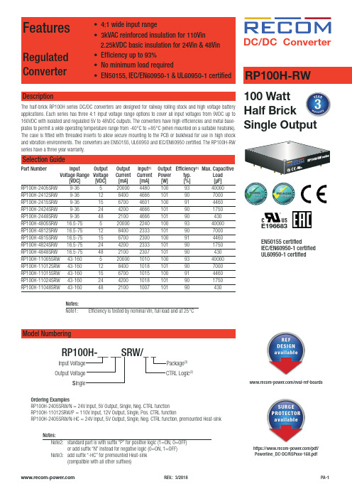
FeaturesRegulated Converter• 4:1 wide input range• 3kVAC reinforced insulation for 110Vin 2.25kVDC basic insulation for 24Vin & 48Vin • Efficiency up to 93%• No minimum load required• EN50155, IEC/EN60950-1 & UL60950-1 certifiedDescriptionThe half-brick RP100H series DC/DC converters are designed for railway rolling stock and high voltage battery applications. Each series has three 4:1 input voltage range options to cover all input voltages from 9VDC up to 160VDC with isolated and regulated 5V to 48VDC outputs. The converters have high efficiencies and metal base-RP100H-RW DC/DC Converter100 Watt Half BrickEN50155 certifiedIEC/EN60950-1 certified UL60950-1 certifiedE196683RP100H-2415SRW 9-36 15 6700 4601 100 91 4460RP100H-2424SRW 9-36 24 4200 4666 101 90 1750RP100H-2448SRW 9-36 48 2100 4666 101 90 430RP100H-4805SRW 16.5-75 5 20000 2240 100 93 40000RP100H-4812SRW 16.5-75 12 8400 2333 101 90 7000RP100H-4815SRW 16.5-75 15 6700 2300 100 91 4460RP100H-4824SRW 16.5-75 24 4200 2333 101 90 1750RP100H-4848SRW 16.5-75 48 2100 2307 101 90 430RP100H-11005SRW 43-160 5 20000 1010 100 93 40000RP100H-11012SRW 43-160 12 8400 1018 101 90 7000RP100H-11015SRW 43-160 15 6700 1015 100 91 4460RP100H-11024SRW 43-160 24 4200 1018 101 90 1750RP100H-11048SRW 43-160 48 2100 1007 101 90 430Ordering ExamplesRP100H-2405SRW/N = 24V Input, 5V Output, Single, Neg. CTRL function RP100H-11012SRW/P = 110V Input, 12V Output, Single, Pos. CTRL functionRP100H-2405SRW/N-HC = 24V Input, 5V Output, Single, Neg. CTRL function, premounted Heat-sinkModel NumberingInput Voltage Output VoltageS ingleRP100H-__ __SRW/_ _Notes:Note2: standard part is with suffix “P” for positive logic (1=ON, 0=OFF) or add suffix “N” instead for negative logic (0=ON, 1=OFF) Note3: add suffix “-HC” for premounted Heat-sink CTRL Logic (2)Package (3)Notes:Note1:Efficiency is tested by nominal Vin, full load and at 25°Chttps:///pdf/Powerline_DC-DC/RSPxxx-168.pdf/eval-ref-boardsSpecifications (measured @Ta = 25°C, resistive load, nominal Vin and rated Iout unless otherwise noted)Specifications (measured @Ta = 25°C, resistive load, nominal Vin and rated Iout unless otherwise noted)RP100H-4805SRW708090100Efficiency vs. Output CurrentPower up Start-up CharacteristicON/OFF Control Start-up Rise CharacteristicSpecifications (measured @Ta = 25°C, resistive load, nominal Vin and rated Iout unless otherwise noted)Efficiency vs. Input Voltage60708090100708010090RP100H-11005SRWEfficiency vs. Output CurrentPower up Start-up CharacteristicSpecifications (measured @Ta = 25°C, resistive load, nominal Vin and rated Iout unless otherwise noted)OUTPUT TRIM Typical Output Ripple and NoisePower up Start-up CharacteristicOutput Voltage TrimmingRP100H-RW converters offer the feature of trimming the output voltage over a certain range around the nominal value by using external trim resistors. The values for trim resistors shown in trim tables below are according to standard E96 values; therefore, the specified voltage may slightly vary; they also can be calculated with below shown equation.TRIM DOWNTRIM UPTRIM-Sense+SenseSpecifications (measured @Ta = 25°C, resistive load, nominal Vin and rated Iout unless otherwise noted)OUTPUT TRIMRP100H-xx05SRWRP100H-xx12SRWRP100H-xx15SRWRP100H-xx24SRWRP100H-xx48SRWTrim Down all Vout‘sTrim up 12345678910%Vout = 5.05 5.10 5.15 5.20 5.25 5.30 5.35 5.4 5.45 5.50Volts R 1 = 30915810578.763.453.646.440.236.533.2kOhms Trim up 12345678910%Vout =12.1212.2412.3612.4812.6012.7212.8412.9613.0813.20Volts R 1 = 88745330122618215413311810595.3kOhms Trim up 12345678910%Vout =15.1515.3015.4515.6015.7515.9016.0516.2016.3516.50Volts R 1 = 1130576383294237196169150137124kOhms Trim up 12345678910%Vout =24.2424.4824.7224.9625.2025.4425.6825.9226.1626.40Volts R U = 1870953634487392324280249226205kOhms Trim up 12345678910%Vout =48.4848.9649.4449.9250.4050.8851.3651.8452.3252.80Volts R 1 = 3830196013001000806681576511464422kOhms Trim down 12345678910%R 2 = 97.647.531.623.217.814.712.110.59.098.06kOhms Trim down 11121314151617181920%R 2 =7.156.345.765.114.644.223.923.573.243.01kOhmsTrim CalculationVout = Output VoltageR 1 =100*Vout+D Vout * Vout)- (100+2D Vout) k Ω D Vout = Output Voltage Trim in %1.225*D Vout D VoutR1 =trim up resistorR2 = trim down resistor R 2 = 100 - 2 k ΩD Vout Practical Example:Trim Up:Vout = 5V, D Vout = 10% (5.5V)R 1 =100*Vout+D Vout * Vout) - (100+2D Vout) k Ω = 100*5 +10*5 - 100+2*10= 44.89 - 12 = 32.9k Ω 1.225*D Vout D Vout 1.225*10 10Trim down:Vout = 5V, D Vout = -10% (4.5V)R 2 = 100 - 2 k Ω = 100 - 2 = 8.06k ΩD Vout 10Specifications (measured @Ta = 25°C, resistive load, nominal Vin and rated Iout unless otherwise noted)REGULATIONSParameter Condition ValueOutput Accuracy±1.0%Line Regulation low line to high line at full load±0.1% Load Regulation0% to 100% load0.1% Transient Response25% load step change200µs typ.; 250µs max.Transient Response to Dynamic Load Change from 100% to 75% to 100% of Full Load at nom.VinRP100H-4805SRWRP100H-2405SRWRP100H-11005SRWSpecifications (measured @Ta = 25°C, resistive load, nominal Vin and rated Iout unless otherwise noted)ENVIRONMENTALParameterCondition ValueOperating Case Temperature Range refer to derating graphMaximum Case Temperature 105°CTemperature Coefficient ±0.02%/°C max.Thermal Impedance vertical direction by natural convection (0.1m/s) without Heat-sink vertical direction by natural convection (0.1m/s) with Heat-sink6.7°C/W 4.7°C/W Operating Humidity 5% - 95% RHPollution Degree PD2Shock according to EN61373 standard Thermal Shock according to MIL-STD-810F standardVibrationaccording to EN61373 standardFire protection on railway vehicles according to EN45545-2, 2013 standardMTBFaccording to MIL-HDBK-217F standard, 25°C408.7 x 103 hoursPROTECTIONSParameterConditionValueShort Circuit Protection (SCP)below 100m Ωcontinuous, automatic recovery Over Voltage Protection (OVP)% of nom. Vout115%-130%, Hiccup Mode Over Load Protection (OLP)% Iout rated24Vin, 48Vin 110Vin120%-150%, Hiccup Mode 150% typ., Hiccup ModeOver Temperature Protection (OTP)+110°C to +120°C Isolation Voltage110VinI/P to O/P I/P or O/P to Case 3kVAC/1minute 1.5kVAC/1minute 24Vin, 48VinI/P to O/P I/P or O/P to Case2.25kVDC/1minute 1.6kVDC/1minuteIsolation Resistance 500 VDC1G Ω min.Isolation Capacitance 2500pF max.Isolation Grade110 Vin 24Vin, 48Vin reinforced insulationbasic insulationThermal CalculationNotes:Note4: Refer to local wiring regulations if input over-current protection is also required. Recommended fuse: T35A slow blow.R thcase-ambient = 6.7°C/W (vertical) T case = Case Temperature R thcase-ambientHC = 4.7°C/W (vertical) T ambient = Environment Temperature P dissipation = Internal lossesR thcase-ambient = T case - T ambientP IN = Input PowerP dissipationP OUT = Output Power h = Efficiency under given Operating ConditionsP dissipation = P IN - P OUT = P OUTapp- P OUTapp R thcase-ambient = Thermal Impedance h Practical Example:Take the RP100H-2405SRW with 9V input Voltage and 50% load. What is the maximum ambient operating temperature? Use converter vertical in application without airflow.Eff min = 91% @ V nomP OUT = 100W P OUTapp = 100 x 0.5 = 50W h = 91% (Efficiency vs. Load Graph)without Heat-sink with Heat-sinkR th = T casemax - T amb --> 6.7°C/W = 105-T amb R thHC = T casemax - T amb--> 4.7°C/W = 105-T amb P dissipation 4.95W P dissipation4.95W T amb = 72°C T ambHC = 82°CSpecifications (measured @Ta = 25°C, resistive load, nominal Vin and rated Iout unless otherwise noted)Specifications (measured @Ta = 25°C, resistive load, nominal Vin and rated Iout unless otherwise noted)DC/DC ConverterSpecifications (measured @Ta = 25°C, resistive load, nominal Vin and rated Iout unless otherwise noted)RP100H-RWSeriesConducted Emission EN55022 Class AConducted Emission EN55022 Class AC4C5C6C7C8Shield PlaneL1C18+V INEMI Filtering according to EN55022/11 Class A and EN50121-1 (110Vin)DC/DC ConverterSpecifications (measured @Ta = 25°C, resistive load, nominal Vin and rated Iout unless otherwise noted)RP100H-RWSeriescontinued on next pageEMI Filtering according to EN55022/11 Class B (24Vin and 48Vin)Shield Plane100-110xxSRW, Class BNNC6C9C8C3C4CaseL2C7C19C20Shield PlaneC12C13C14C10C11C16C2C4L1L2C5C8C6C7C11C3Conducted Emission EN55022 Class ADC/DC ConverterSpecifications (measured @Ta = 25°C, resistive load, nominal Vin and rated Iout unless otherwise noted)RP100H-RWSeriesEMI Filtering according to EN55022/11 Class B (110Vin)C8Shield PlaneShield PlaneC9C1C2C3C11C12C10CaseL1C4C5C8C13C14C17C9C19C3C4L1L2C12C10C11C15C15Shield PlaneC9C10C12Conducted Emission EN55022 Class BSpecifications (measured @Ta = 25°C, resistive load, nominal Vin and rated Iout unless otherwise noted)Specifications (measured @Ta = 25°C, resistive load, nominal Vin and rated Iout unless otherwise noted)The product information and specifications may be subject to changes even without prior written notice.The product has been designed for various applications; its suitability lies in the responsibility of each customer. The products are not authorized for use in safety-critical applications without RECOM’s explicit written consent. A safety-critical application is an application where a failure may reasonably be expected to endanger or cause loss of life, inflict bodily harm or damage property. The applicant shall indemnify and hold harmless RECOM, its affiliated companies and its representatives against any damage claims in connection with the unauthorizeduse of RECOM products in such safety-critical applications.PACKAGING INFORMATIONParameterTypeValuePackaging Dimension traywithout Heat-sink with Heat-sink157.0 x 88.0 x 12.8mm 157.0 x 88.0 x 24.8mmPackaging Quantity 2pcs.Storage Temperature Range -55°C to +125°C Storage Humidity5% - 95% RH。
ERA5资料在蓟州复杂地形下的检验与应用

海 洋 气 象 学 报
JOURNAL OF MARINE METEOROLOGY
2024 年 2 月
Vol.44 No.1
Feb.ꎬ 2024
邹双泽ꎬ白爱娟ꎬ何科ꎬ等.ERA5 资料在蓟州复杂地形下的检验与应用[ J] .海洋气象学报ꎬ2024ꎬ44(1) :118 ̄128.
can reflect the change of weather and provide reference for analyzing strong convective potential.
Keywords Jizhouꎻ Daxing sounding stationꎻ ECMWF Reanalysis v5 ( ERA5 ) ꎻ aerial explorationꎻ
发展专项( CXFZ2022J012)
第一作者简介:邹双泽ꎬ女ꎬ硕士ꎬ工程师ꎬ主要从事灾害性天气监测预警研究ꎬ317973133@ qq.comꎮ
通信作者简介:白爱娟ꎬ女ꎬ博士ꎬ教授ꎬ主要从事天气动力学研究ꎬbaiaj@ cuit.edu.cnꎮ
第1期
邹双泽等:ERA5 资料在蓟州复杂地形下的检验与应用
难ꎮ 又如河南郑州“720” 特大暴雨[4-5] ꎬ造成全市
需要验证ꎮ
暴雨[1-3] ꎬ引发的城市内涝和山区泥石流造成 78 人遇
380 人因灾死亡或失踪ꎮ 在特定天气形势和环境条
得到广泛应用[16] ꎬ但在复杂地形区资料的可靠性仍
一方面ꎬ处于复杂地形的天津蓟州短时强降水
件下产生的强对流天气是短时临近预报的重难点ꎬ高
strong convective index
辨率高的优点ꎬ能够提供对流层各高度层的温度、湿
海康威视 DS-1100K 系列网络键盘 快速入门指南说明书
DS-1100K系列网络键盘快速入门指南法律声明版权所有©杭州海康威视数字技术股份有限公司2020。
保留一切权利。
本手册的任何部分,包括文字、图片、图形等均归属于杭州海康威视数字技术股份有限公司或其关联公司(以下简称“海康威视”)。
未经书面许可,任何单位或个人不得以任何方式摘录、复制、翻译、修改本手册的全部或部分。
除非另有约定,海康威视不对本手册提供任何明示或默示的声明或保证。
关于本产品本手册描述的产品仅供中国大陆地区销售和使用。
本产品只能在购买地所在国家或地区享受售后服务及维保方案。
关于本手册本手册仅作为相关产品的指导说明,可能与实际产品存在差异,请以实物为准。
因产品版本升级或其他需要,海康威视可能对本手册进行更新,如您需要最新版手册,请您登录海康威视官网查阅( )。
海康威视建议您在专业人员的指导下使用本手册。
商标声明• 为海康威视的注册商标。
•本手册涉及的其他商标由其所有人各自拥有。
责任声明•在法律允许的最大范围内,本手册以及所描述的产品(包含其硬件、软件、固件等)均“按照现状”提供,可能存在瑕疵或错误。
海康威视不提供任何形式的明示或默示保证,包括但不限于适销性、质量满意度、适合特定目的等保证;亦不对使用本手册或使用海康威视产品导致的任何特殊、附带、偶然或间接的损害进行赔偿,包括但不限于商业利润损失、系统故障、数据或文档丢失产生的损失。
•您知悉互联网的开放性特点,您将产品接入互联网可能存在网络攻击、黑客攻击、病毒感染等风险,海康威视不对因此造成的产品工作异常、信息泄露等问题承担责任,但海康威视将及时为您提供产品相关技术支持。
•使用本产品时,请您严格遵循适用的法律法规,避免侵犯第三方权利,包括但不限于公开权、知识产权、数据权利或其他隐私权。
您亦不得将本产品用于大规模杀伤性武器、生化武器、核爆炸或任何不安全的核能利用或侵犯人权的用途。
•如本手册内容与适用的法律相冲突,则以法律规定为准。
鲨鲨鲨2O防水音箱用户手册说明书
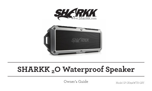
SHARKK 2O Waterproof Speak er Owner’s Guide www Model SP-SK896WTR-GRYIntroductionThank you for your purchase of the SHARKK 2O Waterproof Speaker. Please read this manual carefully before you begin using your new item.Packed with advanced features and equipped with the absolute latest in wireless technology the SHARKK 2O Waterproof & Dustproof Speaker is a powerful, rugged and reliable speaker, making it the perfect option for those with an active lifestyle. Unlike the majority of it’s less adventurous ancestors, who were apt to leave you hanging at the slightest hint of moisture, this IP67-rated Waterproof & Dustproof Speaker will always have your back, and will keep you rockin’ through damp and dry.Throw in the sturdy velcro carry-strap and robust exterior design, and you’ve got a portable powerhouse that blends function, style and rugged determination.2Introduction In addition to the SHARKK 2O Waterproof Speaker, the SHARKK Lifestyle Brand is pleased to be able to offer a wide variety of consumer accessories across many different product categories. Keyboards, mobile device cases, speakers, power banks and computer mice are but a few of the items that make up our extensive online catalog and we welcome you to visit us and browse our handpicked selection of the latest consumer accessories at .Here at SHARKK, the quality of our products and the complete satisfaction of our customers are the two greatest passions of our enterprise, as we endeavor to bring you top quality items at competitive prices.3Product OverviewBox Content•1x 8W Waterproof/Dustproof Bluetooth Speaker •1x Velcro Carrying Strap•1x Custom Storage Bag•1x USB Charging Cable•1x AUX Cable•1x Power Adapter•1x User Manual45Product Overview6Product OverviewNFC Area •Hold your device over this icon to use NFC for Bluetooth connection.M(ode) Button* •Use this button to toggle between Bluetooth/AUX/Micro SD modes.Prev • Use this button to navigate to the previous track.• Press and hold to rewind.*Note: when connecting an AUX cable or SD Card, the speaker will automatically enter the cor-rect mode, provided that only one mode of connection is in use. If there are multiple connections, the speaker will default to Bluetooth mode, and you can toggle between modes using the M button. 1237Product OverviewNext • Use this button to navigate to the next track.• Press and hold to fast-forward.Play/Pause•While in Bluetooth mode, press and hold this button to begin pairing device.• Use normally to control playback. Bluetooth Indicator •Flashing Blue: Device is in bluetooth mode (default)•Flashing Blue/Red: Active Bluetooth pairing.• Solid Blue: Bluetooth connection established.4568Product OverviewAUX/Micro SD Indicator •Red: Device is in AUX mode.•Green: Device is in Micro SD mode.V(olume)-•Decrease Volume.V(olume)+ •Increase Volume. • A beeping sound will alert you when you have reached maximum volume.Phone Button •When connected via Bluetooth, press and hold to activate Siri or S-Voice. •Incoming Call: press once to answer, press and hold to reject/end call.910879Product OverviewMicrophone •For best results, keep within 3 feet of the mic while speaking.Battery-Level Indicator •Power Button/Indicator •Press and hold for 2 seconds to power on, or 4 seconds to power off. •If nessecary, press and hold for 8 seconds to force a system restart.11121310Product OverviewMicro USB Port •For charging use only, cannot be used for external device connection.AUX IN Port •Use this port to connect speaker to an external media device via AUX cord.Micro SD Slot* •Insert a Micro SD card into this slot to play stored media. If there is no card inserted, Micro SD mode will be skipped when toggling between modes. •All tracks/folders on the card will play in alphabetical order.*Note: Due to technical limitations, the speaker can only play audio from a microSD card that is formatted as FAT32 and not NTFS. If you are having difficulty playing music from your card, please check that your card is formatted correctly.141516Instructions ChargingInsert the power cord into the Micro-USB port of the device. Charging begins automatically even if the device is powered off. All three power indicator lights will turn solid when device is fully charged.To conserve energy, the device will automatically power off if there is no Blue-tooth connection and the device has been idle for 10 minutes.Bluetooth1. To connect your speaker to a Bluetooth enabled device, power on yourspeaker and hold your phone or other device within 3 feet of the speaker,press and hold the Play/Pause button for 3 seconds, and the system will then enter pairing mode (signaled by a voice prompt) and you should see theindicator light flashing blue and red.11Instructions2. Pairing mode will automatically be canceled (signaled by a beep) after 3minutes. To re-enter pairing mode, simply begin again at step #1.3. Make sure that Bluetooth is enabled on the device you wish to pair with.4. When scanning for available devices, the speaker should appear as“SHARKK” on the list of found devices.5. When selecting “SHARKK” from the list, you may be prompted to enter aPIN code (sometimes called a “Passkey”, “PIN Number” or “Password”), the code for this device is “0000”.6. The speaker will record this device as the last device paired.7. Finally, activate the Bluetooth connection from your phone or other device(some devices may do this automatically).8. Incoming calls will override music and other media with an “incoming call”voice alert, simply press the Phone button to answer or press and hold to12Instructions reject/end the call. Press the Phone button to answer a second incoming call.9. Press the Phone button to activate the “siri” or S-Voice function of your phone. NFC1. Begin by powering on your speaker and turning on the NFC function of thedevice you wish to connect to your speaker.2. Touch the device to the NFC area of your speaker and the speaker shouldconnect automatically.Waterproof & Dustproof• The SHARKK 2O Waterproof Speaker has an IP67 rating which means that it is built to withstand complete immersion in water up to 1m and that it is completely impervious to dust.• Secure protective side-flap covering before use near water.13FeaturesFeatures1. Bluetooth Version 4.0.2. Increased Bluetooth transmission rate and higher audio fidelity withdecreased power consumption.3. Supports: NFC, Siri and S-Voice.4. Battery status shows on iPhone/ iPod / iPad.5. Dual 4W loudspeakers produce high quality stereo sound.6. IP67 Waterproof/Dustproof Rating.7. Supports AUX/Micro SD Card.8. Equipped with automatic power-saving feature.14Specifications Specifications1. Operation Voltage: 3.7 V2. Charging Voltage: 5V3. Output Power: 4Watts * 24. Speaker Spec.: 40mm 2 Ohms 4W5. Frequency Response: 60Hz ~ 20Khz6. Lithium Battery Capacity: 2200mA7. THD < 0.5%8. SNR > 90dB9. Dimensions: 55mm * 75mm * 175mm15InstructionsProper Use1. To prevent damage and risk of electrical shock, do not expose this device todust, vibration, or extreme weather.2. Do not place device in close proximity to open flames or extreme heatsources. Always place your device on level, flat and stable surfaces.3. Avoid placing items on top of the speakers.4. Do not use excessive force when pressing buttons or handling your device.5. To clean your speaker, use only a dry, soft cloth or minimally damp clothwithout any device solvent or cleaning agent.6. Please do not allow the use of these speakers by small children withoutproper adult supervision.16Appendix SafetyTo prevent fires, shock or injury, please do not disassemble or replace any parts of your device. In the event that your device may be damaged or in need of repair, please contact a professional maintenance or qualified service center for assistance. We are not responsible for any personal injury or property damage caused by improper use of this product.FCC CompliantThese devices comply with part 15 of the FCC Rules. Operation is subject to the following two conditions: (1) This device may not cause harmful interference, and (2) This device must accept any interference received, including interference that may cause undesired operation.17AppendixWarrantyYour new device is covered by a Limited Manufacturer’s Warranty. Details of the warranty are as follows: for a period of one (1) year from the date of retail purchase, SHARKK warrants that this product is free of any defects in manufacturing, materials and workmanship. During the warranty period, we shall, at our sole discretion, repair or replace any defective parts free of charge. SupportAs with all SHARKK products, the SHARKK 2O Waterproof Bluetooth Speaker comes with our quality assurance and satisfaction guarantee. If you should experience any technical issues with your device, or if you have any questions we ******************************************************************, and we will do everything in our power to help resolve the issue.1819Keep In TouchSHARKK @ShopSHARKK @SHARKKLifestylePlease take a moment to check us out on Facebook, Twitter and Instagram where you can post pictures, share your experience and join the ever-growing SHARKK online community.By joining the SHARKK Facebook page you will be eligible for special promo-tions and giveaways, as well as being among the first to know about new products, discounts and sales. ****************** All rights reserved© Sharkk。
KIT-Z100 快速入门指南说明书
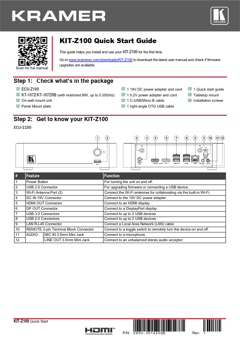
Scan for full manualKIT-Z100 Quick Start GuideThis guide helps you install and use your KIT-Z100 for the first time.Go to /downloads/KIT-Z100 to download the latest user manual and check if firmware upgrades are available.Step 1: Check what’s in the packageECU-Z1001 19V DC power adapter and cord 1 Quick start guide KT-107Z/KT-107ZRB (with restricted BW, up to 5.35GHz) 1 5.2V power adapter and cord Tabletop mount On-wall mount unit 1 C-USB/Micro B cableInstallation screwsPanel Mount plate1 right-angle OTG USB cableStep 2: Get to know your KIT-Z100ECU-Z100KT-107Z/KT-107ZRBBoth Table-top mount and wall mount include the following connectors: • A power connector, when notusing the PoE Ethernet port. • PoE RJ-45 Ethernet Port toconnect to an Ethernet cable. • A USB connector:▪ For the table-top mount, aMicro-USB port, forconnecting an external USB device (for example, a headset or memory disk). ▪ For the wall mount, a Type AUSB port is available using the right-angle OTG USB cable (included).Step 3: Mount ECU-Z100Install ECU-Z100 using one of the following methods:• Attach the rubber feet and place the unit on a flat surface.• Fasten a bracket (included) on each side of the unit and attach it to a flat surface(see /downloads/KIT-Z100).• Mount the unit in a rack using the recommended rack adapter(see /product/KIT-Z100).• Ensure that the environment (e.g., maximum ambient temperature &air flow) is compatible for the device. • Avoid uneven mechanical loading.• Appropriate consideration of equipment nameplate ratings should be used for avoiding overloading of the circuits.• Reliable earthing of rack-mounted equipment should be maintained.Step 4: Mount KT-107Z/KT-107ZRBMounting on a table using one of the following options:Portable Mount: place the tabletop mount on the table. Connected cables remain visible and the table remains intact. Secure Mount: secure the tabletop mount to the table as follows:1. Measure the exact location on the surface of the table where you want to install the KT-107Z/KT-107ZRB.2. Drill a hole in the table and optionally cut the cable pass-through opening according to the cut-out dimensions definedin the user manual.3. Secure the tabletop mount to the table using the M5x60 secure screw.4. Connect the Ethernet port to a PoE-enabled source. Optionally, you can connect the power adapter too (as backup).5. Replace the appropriate cover and place the KT-107Z/KT-107ZRB over the tabletop mount (the is magnetically heldin place), by first inserting the lower part of the then carefully laying the KT-107Z/KT-107ZRB in place.6. Wait for the Home-page to load and then secure the KT-107Z/KT-107ZRB to the tabletop mount from the rear side(using 2 M2x4 screws, supplied with the unit).7. Optionally, lock the tabletop mount with a Kensington locker (not supplied).Mounting on the wall:Before mounting KIT-Z100 on a wall, install an in-wall junction box (recommended boxes are listed in the user manual)1. Attach the on-wall mount unit to the installed junction box (top side up see indication arrows on unit).Connect Ethernet and/or power cables and optionally, insert the right-angle USB cable (supplied) for connecting to an adjacent external USB device.2. Screw the 4 wall-mounting screws (supplied) through the screw openings.The various screw openings fit various types of wall junction boxes.3. On the rear side of the KT-107Z/KT-107ZRB, remove the screwcover and the cover (by slightly pressing downwards and thenpulling out) and set aside.4. Attach the panel mount plate to the rear side of theKT-107Z/KT-107ZRB (using 4 M2x4 screws, supplied).5. Connect the flat cable from the on-wall mount (attached to thein-wall junction box) to the connector on the rear ofKT-107Z/KT-107ZRB.6. Hang the KT-107Z/KT-107ZRB on the wall by sliding the tabs onthe attached panel mount plate over the grooves on the on-wallmount unit.Step 5: Connect inputs and outputsAlways switch OFF the power on each device before connecting it to your KIT-Z100.To achieve specified extension distances, use the recommended Kramer cables available at/product/KIT-Z100. Using third-party cables may cause damage!Microphone and speakers can be connected to ECU-Z100 in the following ways:•Speakers can be connected via LINE OUT connector and/or USB ports.•Microphones cab be connected via MIC IN connector (via amp) and/or USB ports.•Speakerphones (combining a speaker and a microphone) can be connected via USB ports.KT-107Z/KT-107ZRB can be powered in any of the following ways:•Using the power adapter when connected by LAN (without PoE support).•Using the power adapter when connected to LAN by Wi-Fi•By PoE when connecting to Ethernet by PoE-supporting LAN.Step 6: Connect powerConnect the power cord to ECU-Z100 and plug it into the mains electricity.If required, connect the power adapter on the KT-107Z/KT-107ZRB to the Power 2-pin terminal block connector on the tabletop mount and to the mains power.Safety Instructions (See for updated safety information)Caution:•There are no operator serviceable parts inside the unit.Warning:•Use only the power cord that is supplied with the unit.•Disconnect the power and unplug the unit from the wall before installing.•Do not open the unit. High voltages can cause electrical shock! Servicing by qualified personnel only.•To ensure continuous risk protection, replace fuses only according to the rating specified on the product label which located on the bottom of the unit.Step 7: Set and operate KIT-Z100Before setting up the application on KT-107Z/KT-107ZRB, you need to acquire Zoom Rooms licenses.To set and operate the application, go to the Zoom Rooms website at /hc/en-us.To use the Zoom Rooms widget on Kramer Control, go to Zoom Rooms settings at/manuals/kramer/kramer-control/1/en/topic/zoom-room-module.。
聚四氟乙烯性能全参数

1.聚四氟乙烯聚四氟乙烯是用于密封的氟塑料之一。
聚四氟乙烯以碳原子为骨架,氟原子对称而均匀地分布在它的周围,构成严密的屏障,使它具有非常宝贵的综合物理机械性能(表14—9)。
聚四氟乙烯对强酸、强碱、强氧化剂有很高的抗蚀性,即使温度较高,也不会发生作用,其耐腐蚀性能甚至超过玻璃、瓷、不锈钢以至金、铂,所以,素有“塑料王”之称。
除某些芳烃化合物能使聚四氟乙烯有轻微的溶胀外,对酮类、醇类等有机溶剂均有耐蚀性。
只有熔融态的碱金属及元素氟等在高温下才能对它起作用。
聚四氟乙烯的介电性能优异,绝缘强度及抗电弧性能也很突出,介质损耗角正切值很低,但抗电晕性能不好。
聚四氟乙烯不吸水、不受氧气、紫外线作用、耐候性好,在户外暴露3年,抗拉强度几乎保持不变,仅伸长率有所下降。
聚四氟乙烯薄膜与涂层由于有细孔,故能透过水和气体。
聚四氟乙烯在200℃以上,开始极微量的裂解,即使升温到结晶体熔点327℃,仍裂解很少,每小时失重为万分之二。
但加热至400℃以上热裂解速度逐渐加快,产生有毒气体,因此,聚四氟乙烯烧结温度一般控制在375~380℃。
聚四氟乙烯分子间的德华引力小,容易产生键间滑动,故聚四氟乙烯具有很低的摩擦系数及不粘性,摩擦系数在已知固体材料中是最低的。
聚四氟乙烯的导热系数小,该性能对其成型工艺及应用影响较大。
其不但导热性差,且线膨胀系数较大,加入填充剂可适当降低线膨胀系数。
在负荷下会发生蠕变现象,亦称作“冷流”,加入填充剂可减轻蠕变程度。
聚四氟乙烯可以添加不同的填充剂,选择的填充剂应基本满足下述要求:能耐380℃高温即四氟制品的烧结温度;与接触的介质不发生反应;与四氟树脂有良好的混入性;能改善四氟制品的耐磨性、冷流性、导热性及线膨胀系数等。
常用的填充剂有无碱无蜡玻璃纤维、石墨、碳纤维、MoS2、A123、CaF2、焦炭粉及各种金属粉。
如填充玻璃纤维或石墨,可提高四氟制品的耐磨、耐冷流性,填充MoS2可提高其润滑性,填充青铜、钼、镍、铝、银、钨、铁等,可改善导热性,填充聚酰亚胺或聚苯酯,可提高耐磨性,填充聚苯硫醚后能提高抗蠕变能力,保证尺寸稳定等。
Panasonic DMC-ZS8 用户手册说明书

Basic Owner’s Manualthis product, please read the instructionscompletely.Dear Customer,Thank you for choosing Panasonic!You have purchased one of the most sophisticated and reliable products on the market today. Used properly, we’re sure it will bring you and your family years of enjoyment. Please take the time to fill in the information below.The serial number is on the tag located on the underside of your Camera. Be sure to retain this manual as your convenient Camera information source. Please note that the actual controls and components, menu items, etc. of your Digital Camera may look somewhat different from those shown in the illustrations in this Owner’s Manual.Carefully observe copyright laws.•Recording of pre-recorded tapes or discs or other published or broadcast material for purposes other than your own private use may infringe copyright laws. Even for the purpose of private use, recording of certain material may be restricted.Model No.Serial No.This Class B digital apparatus complies with Canadian ICES-003.WARNING:TO REDUCE THE RISK OF FIRE, ELECTRIC SHOCK OR PRODUCT DAMAGE,•DO NOT EXPOSE THIS APPARATUS TO RAIN, MOISTURE, DRIPPING OR SPLASHING AND THAT NO OBJECTS FILLED WITH LIQUIDS,SUCH AS VASES, SHALL BE PLACED ON THE APPARATUS.•USE ONLY THE RECOMMENDED ACCESSORIES.•DO NOT REMOVE THE COVER (OR BACK); THERE ARE NOUSER SERVICEABLE PARTS INSIDE. REFER SERVICING TOQUALIFIED SERVICE PERSONNEL.■Product identification markingProduct LocationDigital camera BottomBattery charger Bottom■About the battery packCAUTIONBattery pack (Lithium ion battery pack)•Use the specified unit to recharge the battery pack.•Do not use the battery pack with equipment other than the specified unit.•Do not get dirt, sand, liquids, or other foreign matter on the terminals.•Do not touch the plug terminals (+ and −) with metal objects.•Do not disassemble, remodel, heat or throw into fire.If any electrolyte should come into contact with your hands or clothes, wash it off thoroughly with water.If any electrolyte should come into contact with your eyes, never rub the eyes. Rinse eyes thoroughly with water, and then consult a doctor.CAUTIONDanger of explosion if battery is incorrectly replaced. Replace only with the same or equivalent type recommended by the manufacturer. Dispose of used batteries according to the manufacturer’s instructions.•Do not heat or expose to flame.•Do not leave the battery(ies) in an automobile exposed to direct sunlight for a long period of time with doors and windows closed.Warning Array Risk of fire, explosion and burns. Do not disassemble, heat above 60 °C (140 °F) or incinerate.■About the battery chargerCAUTION!DO NOT INSTALL OR PLACE THIS UNIT IN A BOOKCASE, BUILT-IN CABINET OR IN ANOTHER CONFINED SPACE. ENSURE THE UNIT IS WELL VENTILATED. TO PREVENT RISK OF ELECTRIC SHOCK OR FIRE HAZARD DUE TO OVERHEATING, ENSURE THAT CURTAINS AND ANY OTHER MATERIALS DO NOT OBSTRUCT THE VENTILATION VENTS.Battery chargerThis battery charger operates on AC between 110 V and 240 V.But•In the U.S.A. and Canada, the battery charger must be connected toa 120 V AC power supply only.•When connecting to an AC supply outside of the U.S.A. or Canada, use a plug adaptor to suit the AC outlet configuration.■Cautions for Use•Do not use any other AV cables except the supplied one.•Do not use any other USB connection cables except the supplied one.Keep this unit as far away as possible from electromagnetic equipment (such as microwave ovens, TVs, video games etc.).•If you use this unit on top of or near a TV, the pictures and/or sound on this unit may be disrupted by electromagnetic wave radiation.•Do not use this unit near cell phones because doing so may result in noise adversely affecting the pictures and/or sound.•Recorded data may be damaged, or pictures may be distorted, by strong magnetic fields created by speakers or large motors.•Electromagnetic wave radiation generated by microprocessors may adversely affect this unit, disturbing the pictures and/or sound.•If this unit is adversely affected by electromagnetic equipment and stops functioning properly, turn this unit off and remove the battery or disconnect AC adaptor (DMW-AC5PP; optional). Then reinsert the battery or reconnect AC adaptor and turn this unit on.Do not use this unit near radio transmitters or high-voltage lines.•If you record near radio transmitters or high-voltage lines, the recorded picturesand/or sound may be adversely affected.Information for Your Safety (2)Check that all the accessories are supplied before using the camera. Partnumbers are as of January 2011.Battery pack DMW-BCG10PP•Charge the batterybefore use.battery pack or battery in thetext.Battery chargerDE-A65BBattery charger is indicated as battery charger or charger inthe text.Hand strapVFC4297K1HY08YY0017AV cableK1HY08YY0018CD-ROM VFF0771 •Software:Use it to install the software on your PC. •Owner’s Manual•Cards are optional. You can record or play back pictures on the built-in memory when you are not using a card.•If any accessories are lost, customers should contact 1-800-99-LUMIX (1-800-995-8649) for further information about obtaining replacement parts.•Please dispose of all packaging appropriately.•Keep small parts in a safe place out of the reach of children.Before useStandard accessories ................7Names of parts. (8)Cursor button (9)PreparationsCharging the battery (10)Inserting and removing the card (optional)/the battery (12)Picture save destination(cards and built-in memory) (13)Setting the clock .......................14Setting the menu . (15)BasicsSelecting theRecording Mode .......................16Taking pictures with automatic settings[Intelligent Auto] Mode (17)AF Tracking (18)Taking motion pictures [Motion Picture] Mode ..............19Viewing your pictures[Normal Play] ............................20Deleting pictures . (20)OthersReading the Owner’s Manual (PDF format) ..............................21Specifications ...........................23Optional accessories (26)We recommend you use a battery with sufficient battery power or the AC adaptor when recording motion pictures.●If the power supply is cut off due to a power cut or the AC adaptor being disconnected, the motion picture being recorded using the AC adaptor will not be recorded.●Always use a genuine Panasonic AC adaptor (DMW-AC5PP: optional).●When using an AC adaptor, ensure that the Panasonic DC coupler (DMW-DCC5; optional) and AC adaptor (DMW-AC5PP; optional) are used.■About batteries that you can use with this unitThe battery that can be used with this unit is DMW-BCG10PP.It has been found that counterfeit battery packs which look very similar to the genuine products are made available to purchase in some markets. Some of these battery packs are not adequately protected with internal protection to meet the requirements of appropriate safety standards. There is a possibility that these battery packs may lead to fire or explosion. Please be advised that we are not liable for any accident or failure occurring as a result of use of a counterfeit battery pack. To ensure that safe products are used we recommend that a genuine Panasonic battery pack is used.•Use the dedicated charger and battery.•The camera has a function for distinguishing batteries which can be used safely. The dedicated battery (DMW-BCG10PP) supports this function. The only batteries suitable for use with this unit are genuine Panasonic products and batteries manufactured by other companies and certified by Panasonic. (Batteries which do not support this function cannot be used.) Panasonic cannot in any way guarantee the quality, performance or safety of batteries which have been manufactured by other companies and are not genuine Panasonic products.•The battery is not charged when the camera is shipped. Charge the battery and set the clock before use.•Charge the battery with the charger indoors (10 °C - 30 °C (50 °F - 86 °F)).Recording conditions by CIPA standard•CIPA is an abbreviation of [Camera & Imaging Products Association].•[Program AE] Mode.•Temperature: 23 °C (73.4 °F)/Humidity: 50 %RH when LCD monitor ison.•Using a Panasonic SD Memory Card (32 MB).•Using the supplied battery.•Starting recording 30 seconds after the camera is turned on. (When theOptical Image Stabilizer function is set to [ON].)•Recording once every 30 seconds with full flash every secondrecording.•Rotating the zoom lever from Tele to Wide or vice versa in everyrecording.•Turning the camera off every 10 recordings and leaving it until thetemperature of the battery decreases.The number of recordable pictures or available operating time may vary accordingto surrounding environment and usage conditions. Figures may be reduced if flash,zoom, or other functions are used frequently, or in colder climates.Ensure [LUMIX] faces outwards.●Always use genuine Panasonic batteries (DMW-BCG10PP).●If you use other batteries, we cannot guarantee the quality of this product.●Insert the card fully, otherwise it may be damaged.Confirm the SD speed by checking the card label or other card related materials.(Example)●Latest information:http://panasonic.jp/support/global/cs/dsc/(This Site is English only.)●Keep the Memory Card out of reach of children to prevent swallowing.Max. T: 1 m (3.28 feet) and above (7 × to 11 × is 2 m (6.57 feet) to ∞)■Automatic Scene DetectionCamera identifies scene when pointed at subject, and makes optimum settings automatically. The type of scene detected is indicated by a blueIf the camera automatically identifies the scene and determines that people appear as subjects in the picture (, , ), Face Detection is activated, and the focus and exposure are adjusted for the recognized faces.AF TrackingEven if a subject, where the focus was locked (AF Lock) moves, the•Press ▲ again to cancel.Align the AF Tracking frame with the subject, and The optimum scene is detected for the subject where the focus was locked (AF Lock).•AF Lock successful: Yellow •AF Lock failed: Red (flash) •Press ▼ to cancel.This records motion pictures with audio. (Recording with muted sound is not possible. Sound recording is monaural.) Zoom can also be usedSlide the [REC/PLAY] switch toSet the mode dial to Elapsed recording timeRemaining recording time (approx.)Press halfway (Adjust the focus)Press fully (start recording)Press fully●Immediately release the shutter button after pressing it all the way.●When there is no space left to store the motion picture, recording automatically ends.●A maximum of approx. 2 GB of continuous motion picture can be recorded. (Even if there is more than 2 GB of available space on the card, the available recording time will be calculated for a maximum of 2 GB.)Deleting picturesPlayback Mode:To play back a motion picture, select an image with ◄ or ►, and then press ▲ to start playback.You can print pictures by connecting a camera to your computer or printer, or by giving an SD card to a shop assistant at a photo shop.To return to the install menu. See next page.Double click the “Owner’s Manual” shortcut icon on the desktop■When the Owner’s Manual (PDF format) will not open Array You will need Adobe Acrobat Reader 5.0 or later or Adobe Reader 7.0or later to browse or print the Owner’s Manual (PDF format).Vista SP2 / Windows 7•You can download and install a version of Adobe Reader that you can use with your OS from the following Web Site./reader/otherversions■To uninstall the Owner’s Manual (PDF format)Delete the PDF file from the “Program Files\Panasonic\Lumix\” folder.•When the contents in the Program Files folder cannot be displayed,click the “Show the contents of this folder” to display them.Battery chargerEquipment mobility: Movable Battery Pack (lithium-ion)MEMO Product name: Battery PackProduct no.: DMW-BCG10PP●Performance identical to supplied battery pack.●Recommended for taking on holiday, etc.Product name: AC adaptor*Product no.: DMW-AC5PPPurchase the AC adaptor and DC coupler as a set. They cannot be usedindividually with this camera.Product name: Marine CaseProduct no.: DMW-MCTZ20Product name: DC coupler*Produce no.: DMW-DCC5Product name: SDXC Memory CardProduct no.: 48 GB: RP-SDW48GU1K Class 1064 GB: RP-SDW64GU1K Class 10Product name: SDHC Memory CardProduct no.: 4 GB: RP-SDW04GU1K Class 104 GB: RP-SDN04GU1A Class 48 GB: RP-SDW08GU1K Class 108 GB: RP-SDN08GU1A Class 416 GB: RP-SDW16GU1K Class 1016 GB: RP-SDN16GU1A Class 432 GB: RP-SDW32GU1K Class 10Product name: SD Memory CardProduct no.: 2 GB: RP-SDN02GU1A Class 4* T he AC Adaptor (optional) can only be used with the designatedPanasonic DC Coupler (optional). The AC adaptor (optional) cannot beused by itself.●Product numbers are correct as of January 2011. These may be subjectto change.●Accessories and/or model numbers may vary between countries.Consult your local dealer.•SDXC Logo is a trademark of SD-3C, LLC.•QuickTime and the QuickTime logo are trademarks orregistered trademarks of Apple Inc., used under licensetherefrom.•This product uses “DynaFont” from DynaComwareCorporation. DynaFont is a registered trademark ofDynaComware Taiwan Inc.•Other names, company names, and product namesprinted in these instructions are trademarks orregistered trademarks of the companies concerned.Panasonic Canada Inc.5770 Ambler Drive,Mississauga, OntarioL4W 2T3(905) 624-5010www.panasonic.ca© Panasonic Corporation 2011Printed in Japan。
H400钢带剪刀有以下是几种可能的解释
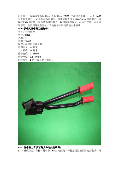
钢带剪刀,长柄重型拆包剪刀,开包剪刀,YBICO手动式钢带剪刀,元贝H400手工钢带剪刀,H410长柄拆包剪刀,需要原装进口(H400/H410钢带剪刀)请找我们-深圳市凯比奇包装器材有限公,我们常年有现货,品质有保障,质量可靠耐用,售后服务完善到位,欢迎你前来咨询洽谈合作事项。
h400手动式钢带剪刀规格书:
名称:钢带剪刀
型号:H400
产地:台
品牌:YBICO
代理:深圳凯比奇包装
剪刀总长:60厘米
刀片长度:15厘米
剪带宽度:9--55mm
剪带厚度:0.1--3.0mm
包装规格:1把一盒4把一件装。
H400钢带剪刀有以下是几种可能的解释:
1、材料或合金:在材料科学中,H400可能是一种特定类型或级别的合金或材料
的标识。
这可能需要查阅相关的材料数据手册或资料才能获取详细信息。
2、设备型号或标准:在某些工程或工业领域中,H400可能代表某种设备、机器或组件的型号或标准。
3、硬件规格或编号:在硬件、计算机或其他电子产品领域,H400可能指的是某种硬件组件的规格或编号。
4、其他领域:在其他领域,H400可能有其特定的含义或用途,由于H400的含义不明确,要获取准确的解释,您可能需要提供更多关于其上下文或使用情境的信息。
如果可能的话,请详细描述您在哪里看到或听到H400,以及它与什么相关,这样可能有助于更准确地确定其含义。
本田+nt1100d+用户手册说明书

用户手册NT1100D 100.202202应将本《用户手册》视为摩托车的永久部件,转售车辆时应将其随车一并交给新车主。
本《用户手册》包含印刷前的最新生产信息。
本田技研工业株式会社保留随时修改规格、设计而不事先通知的权利,并且也不就此承担任何责任。
未经书面许可,不得擅自复制或复印本手册的任何部分。
本《用户手册》中图示的车辆可能与您的实际车辆并不一致。
Сбζ© 2022 本田技研工业(中国)投资有限公司祝贺您选择了全新的本田摩托车!选择了本田产品,您便成为了本田这个全球大家庭的一员,在这个大家庭中,每位成员都有很高的满足感,都非常赏识本田致力于打造每一件优质产品的良好声誉。
为了确保您的安全、增加您驾骑的乐趣:●请仔细阅读本手册。
●请遵照本手册中的所有建议和操作步骤。
●请密切关注本手册中记载的和摩托车车身上粘贴的安全信息。
●本手册中的以下代码代表相应的国家。
国家代码代码车名型号名CH(中国)NT1100D NT1100D您的安全和他人的安全都非常重要。
安全驾骑本摩托车是一项重要的责任。
为了帮助您在安全方面作出明智的决定,我们在安全标签上和本手册中提供了操作步骤和其他信息。
这些信息旨在提醒您注意可能会伤害到您或他人的潜在危险。
当然,要我们列出与摩托车骑乘和保养相关的所有危险是不切实际或不可能的。
您必须自行作出正确判断。
您将会看到各种形式的重要安全信息,其中包括:●摩托车上的安全标签●安全信息,其前面带有安全警示符号和以下三种警示语之一:危险、警告或小心。
三种警示语的含义如下所示:若不遵照指示,将会造成严重的人员伤亡。
若不遵照指示,可能会造成严重的人员伤亡。
若不遵照指示,您可能会受伤。
以下标题的下方列有其他重要信息:帮助您避免损坏摩托车、其他财产或环境的信息。
摩托车安全2操作指南18保养维护203故障处理238相关信息265技术参数285安全指南 (3)图片标签 (7)安全注意事项 (9)驾骑注意事项 (10)配件和改装 (15)装载指南 (16)安全指南3摩托车安全安全指南为了增强您的安全性,请遵照以下指南:●执行本手册指定的所有日常和常规检查。
领世达 KH100 全功能钥匙助手 用户手册说明书
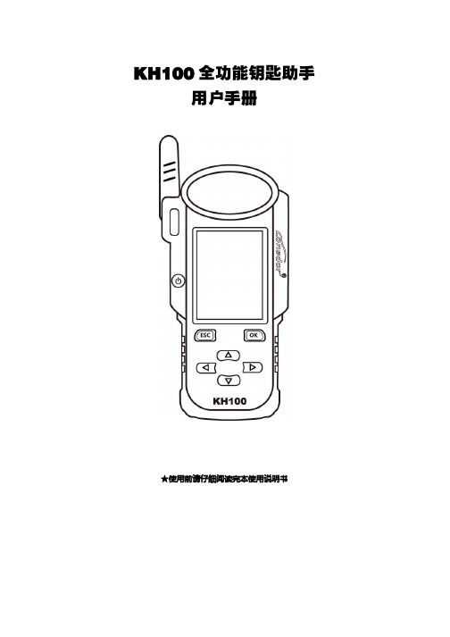
KH100全功能钥匙助手用户手册★使用前请仔细阅读完本使用说明书KH100版权所有领世达对其发行的或与合作公司共同发行的包括但不限产品或服务的全部内容及领世达所属相关网站上的材料、软件等拥有版权等知识产权,受法律保护。
未经本公司书面许可,任何单位及个人不得以任何方式或理由对上述产品、服务、信息、材料的任何部分进行拷贝、修改、抄录、传播或与其他产品捆绑使用、销售等。
凡侵犯本公司版权等知识产权的,我司必依法追究其法律责任!产品领世达KH100全功能钥匙助手及其相关资料仅用于汽车正常维修、诊断及检测,切勿用于违法违规行为。
若因使用我司产品触犯法律法规,本公司不承担任何法律责任。
本产品有一定的可靠性,但不排除可能产生的损失和破坏,对此产生的风险由用户自行承担,本公司不承担任何风险及责任。
声明单位:领世达法律事务部安全须知使用此产品前,请阅读本节信息,并了解这些信息。
有关更详细的信息,请参阅附录的“安全须知事项”。
1、请勿撞击、扔掷、针刺本产品,并避免跌落、挤压、弯曲。
2、请勿在浴室等潮湿的环境中使用本产品,并避免本产品被液体浸湿或冲洗。
在禁止使用本产品的场所,或者使用本产品会引起干扰或危险时,请关闭本产品。
3、请勿在驾驶汽车时使用本产品,以免妨碍安全驾驶。
4、在医疗场所,请遵守有关规定或条例。
在靠近医疗设备的区域,请关闭本产品。
5、在使用高精度的电子设备附近,请关闭本产品,否则可能导致电子设备故障。
6、请勿擅自拆卸本产品及附件,只有授权机构才可维修。
7、请勿将本产品及附件放置于具有强大电磁场的器具中。
8、请将本产品远离磁性设备,磁性设备的辐射会抹掉本产品上存储的信息。
9、请勿在高温处、有易燃气体的地方(如加油站附近)使用本产品。
10、使用本产品时,请遵守相关法律法规,并尊重他人隐私及合法权利。
目录版权声明 (2)安全须知 (3)目录 (4)第一章.注册引导 (4)第二章.产品概述 (5)2.1产品介绍 (5)2.2产品特色 (5)2.3产品参数 (5)2.4整机介绍 (6)2.5功能介绍 (7)2.5.1识别拷贝 (7)2.5.2门禁车库 (7)2.5.3芯片模拟 (8)2.5.4芯片模拟 (8)2.5.1芯片生成 (8)2.5.2遥控生成 (9)2.5.3智能卡生成 (9)2.5.4线圈识别 (9)2.5.4遥控功能 (10)2.5.4特殊功能 (10)2.6升级 (11)第三章.售后服务 (11)保修服务卡 (13)第一章:注册引导注:开机后,请连接好WIFI,进入注册流程。
化工传递过程基础(第三版)习题答案详解_部分3
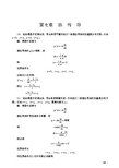
∂t =0 ∂θ ∂t ∂2t ∂t ∂2t ② 一维导热, = 0 , = 0 , 2 = 0 , 2 = 0 ∂y ∂z ∂y ∂z
① 稳态导热,
于是式(7-1)变为
d 2t q + =0 2 k dx
(1)
(2)边界条件为
r = R , t = t0 r = ∞ , t = t∞
(3)式(1)积分两次,可得
t=−
C1 + C2 r
(2)
代入边界条件,可得温度分布表达式为 t − t∞ R = t 0 − t∞ r (4)根据傅里叶定律,可知
q / A = −k dt dr =k
r=R
(3)
t 0 − t∞ R
(1)
取中心面为 x = 0 ,则边界条件为 ① x = 0.2 , t1 = 70 ;② x = −0.2 , t1 = 70 式(1)积分两次,可得
2 1q x + C1 x + C2 2k 、k 数据分别代入式(2) 将边界条件①、②及已知 q ,可得 t=−
C1 = 0 , C2 = 133.66
7-3
在一无内热源的固体热圆筒壁中进行径向稳态导热。当 r1 = 1m 时, t1 = 200 ℃,
r2 = 2m 时, t2 = 100 ℃,其热导率为温度的线性函数,即
式中 k0 为基准温度下的热导率,其值为 k0 = 0.138 W/(m � K) , β 为温度系数,其值为
k = k0 (1 + β t )
(2)
于是此情况下的温度分布方程为
中医诊断名称及代码

中医诊断代码中医诊断名称BN内科病BNF肺系病类BNF010咳嗽病BNF011外感咳嗽病BNF012内伤咳嗽病BNF020肺痿病BNF030肺痈病BNF040哮病BNF050喘病BNF0051暴喘病BNF060肺胀病BNF070肺痨病BNF080咯血病BNF090鼻衄病BNF100失音病BNF110肺衰病BNX心系病类BNX010心悸病BNX0 11惊悸病BNX012怔忡病BNX020胸痹心痛病BNX021卒心痛病BNX030心衰病BNX040不寐病BNX050多寐病BNX060健忘病BNX070癫狂病BNX071癫病BNX072狂病BNX080痫病BNX090昏迷病BNX091神昏病BNX100痴呆病BNX110抽搐病BNX120薄厥病BNX130卒死病BNP脾系病类BNP010胃脘痛病BNP020胃痞病BNP030吐酸病BNP040反胃病BNP050呕吐病BNP051暴吐病BNP060呃逆病BNP070嘈杂病BNP080噎膈病BNP090腹痛病BNP091卒腹痛病BNP100腹胀满病BNP110泄泻病BNP111暴泻病BNP120吐血病BNP130便血病BNP140齿衄病BNP150紫癜病BNP160痰饮病BNP170悬饮病BNP180溢饮病BNP190支饮病BNP000脾系病(便秘病)BNG肝系病类BNG010胁痛病BNG020黄疽病BNG021阴黄病BNG022阳黄病BNG023急黄病BNG030萎黄病BNG040积聚病BNG041积病BNG042聚病BNG050膨胀病BNG051水臌病BNG052气臌病BNG053血臌病BNG054虫臌病BNG060头痛病BNG061头风病BNG070眩晕病BNG080中风病BNG090痉病BNG100厥病BNG101气厥病BNG102血厥病BNG103痰厥病BNG104食厥病BNG105寒厥病BNG106热厥病BNG110郁病BNG120瘿病BNG121气瘿病BNG122肉瘿病BNG123瘿痈病BNG130胆胀病BNS肾系病类BNS010水肿病BNS011阳水病BNS012阴水病BNS020热淋病BNS030石淋病BNS040气淋病BNS050血淋病BNS060膏淋病BNS070劳淋病BNS080乳糜尿病BNS090尿浊病BNS100尿血病BNS110遗尿病BNS120癃闭病BNS130关格病BNS140肾衰病BNS150腰痛病BNS160遗精病BNS161梦遗病BNS162滑精病BNS170早泄病BNS180阳萎病BNS190耳鸣、耳聋病BNS191耳鸣病BNS192耳聋病BNW外感热病类BNW010感冒病BNW011时行感冒病BNW020外感高热病BNW030风温病BNW031风温肺热病BNW040春温病BNW050暑温病BNW060冒暑病BNW070暑秽病BNW080中暑病BNW090湿温病BNW091湿阻病BNW100伏暑病BNW110秋燥病BNW111温燥病BNW112凉燥病BNW120大头瘟病BNW130烂喉痧病BNW140疫毒痢病BNW150太阳病BNW160少阳病BNW170阳明病BNW180太阴病BNW190少阴病BNW200厥阴病BNW000外感热病(痢疾病)BNW000外感热病(疟疾病)BNW000外感热病(霍乱病)BNC虫病类BNC000虫病(蛔虫病)BNC000虫病(绦虫病)BNC000虫病(钩虫病)BNC000虫病(蛲虫病)BNC000虫病(姜片虫病)BNC000虫病(血吸虫病)BNC000虫病(丝虫病)BNC000虫病(囊虫病)BNL内科瘤病类BNL000内科瘤病BNA内科癌病类BNA000内科癌病BNV内科其他病类BNV010内伤发热病BNV020虚病BNV030痿病BNV040汗病BNV041自汗病BNV042盗汗病BNV050痛风病BNV060消渴病BNV070风湿痹病BNV080痹病BNV090骨痹病BNV100肌痹病BNV110面痛病BNV120面瘫病BNV130颤病BNV140急风病BNV150厥脱病BNV160脱病BNV170闭病BNV180肥胖病BNV190中毒病BNV000内科其他病(脚气病)BW外科病BWC疮疡病类BWC010疖病BWC011暑疖病BWC012石疖病BWC013软疖病BWC014蝼蛄疖病BWC020颜面疔疮病BWC030手足疔疮病BWC031蛇眼疔病BWC032蛇头疔病BWC033蛇腹病BWC034托盘疔病BWC035足底病BWC040红丝疔病BWC050烂疔病BWC060疫疔病BWC070痈病BWC071肘痈病BWC072脐痈病BWC073腘窝痈病BWC080丹毒病BWC090发病BWC091锁喉痈病BWC092臀痈病BWC093腓 发病BWC094手发背病BWC095足发背病BWC100有头疽病BWC101脑疽病BWC102发背疽病BWC103膻中疽病BWC104少腹疽病BWC110发颐病BWC120流注病BWC130无头疽病BWC131附骨疽病BWC132环跳疽病BWC133腓疽病BWC140走黄病BWC150内陷病BWC160瘰疬病BWC170流痰病BWC180臁疮病BWC190褥疮病BWC200脱疽病BWC210青蛇毒病BWC220股肿病BWC230痰毒病BWC231颈痈病BWC232腋痈病BWC233胯腹痈病BWR乳房病类BWR010乳头破碎病BWR020乳痈病BWR030乳发病BWR040乳痨病BWR050乳癖病BWR060乳疬病BWR070乳漏病BWR080乳衄病BWR090乳核病BWR100乳疽病BWR110粉刺性乳痈病BWN男性前阴病类BWN010子痈病BWN020子痰病BWN030囊痈病BWN040脱囊病BWN050阴茎痰核病BWN060血精病BWN070精浊病BWN080精癃病BWP皮肤病类BWP010热疮病BWP020蛇串疮病BWP030疣病BWP031扁瘊病BWP032疣目病BWP033鼠乳病BWP040黄水疮病BWP050登豆疮病BWP060癣病BWP061白秃疮病BWP062肥疮病BWP063鹅掌风病BWP064脚湿气病BWP065灰指(趾)甲病BWP066圆癣病BWP067紫白癜风病BWP070湿疮病BWP071奶癣病BWP072旋耳疮病BWP073窝疮病BWP074脐疮病BWP075乳头风病BWP076肾囊风病BWP077四弯风病BWP080火赤疮病BWP090顽湿聚结病BWP100药毒病BWP110瘾疹病BWP120土风疮病BWP130摄颂疮病BWP140风瘙痒病BWP150风热疮病BWP160紫癜风病BWP170白 病BWP180天疱疮病BWP190面游风病BWP200粉刺病BWP210酒齄鼻病BWP220油风病BWP230猫眼疮病BWP240瓜藤缠病BWP250红蝴蝶疮病BWP260皮痹病BWP270狐惑病BWP280流皮漏病BWP290白驳风病BWP300黧黑斑病BWP310蟹足肿病BWP000皮肤病(麻风病)BWP000皮肤病(疥疮病)BWP000皮肤病(鸡眼病)BWP000皮肤病(胼胝病)BWP000皮肤病(淋病)BWP000皮肤病(梅毒病)BWG肛肠病类BWG010悬珠痔病BWG020息肉痔病BWG030肛裂病BWG040肛痈病BWG050肛漏病BWG060脱肛病BWG070肛门湿疡病BWG000肛肠病(痔病)BWG000肛肠病(内痔病)BWG000肛肠病(外痔病)BWG000肛肠病(混合痔病)BWL外科瘤瘤类BWL010气瘤病BWL020血瘤病BWL030肉瘤病BWL040筋瘤病BWL050骨瘤病BWL060脂瘤病BWA外科癌病类BWA010石瘿病BWA020茧唇病BWA030失荣病BWA040乳癌病BWA050肾癌翻花病BWA060锁肛痔病BWV外科其他病类BWV010疝气病BWV011水疝病BWV012狐疝病BWV020肠痈病BWV000外科其他病(水火烫伤BWV000外科其他病(冻疮病)BWV000外科其他病(破伤风病)BWV000外科其他病(毒虫咬伤BWV000外科其他病(毒蛇咬伤BWV000外科其他病(蜈蚣螫伤BWV000外科其他病(蜂螫伤病)BWV000外科其他病(蝎螫伤病)BWV000外科其他病(狗咬伤病)BF妇科病BFY月经病类BFY010月经先期病BFY020月经后期病BFY030月经先后无定期病BFY040月经过多病BFY050月经过少病BFY060经期延长病BFY70痛经病BFY080经间期出血病BFY090闭经病BFY100崩漏病BFY110经行乳房胀痛病BFY120经行发热病BFY130经行头痛病BFY140经行眩晕病BFY150经行身痛病BFY160经行口糜病BFY170经行风疹块病BFY180经行吐衄病BFY190经行泄泻病BFY200经行浮肿病BFY210经行情志异常病BFY220绝经前后诸病BFD带下病类BFD010带下病BFR妊娠病类BFR010妊娠恶阻病BFR020妊娠腹痛病BFR030胎漏病BFR040胎动不安病BFR050滑胎病BFR051堕胎病BFR052小产病BFR060胎萎不长病BFR070胎死不下病BFR080子烦病BFR090子肿病BFR100子满病BFR110子晕病BFR120子痫病BFR130子悬病BFR140子 病BFR150子嗽病BFR160子淋病BFR170转胞病BFR180难产病BFR190胞衣不下病BFR200孕痈病BFC产后病类BFC010产后血晕病BFC011产后血崩病BFC020产后痉病BFC030产后腹痛病BFC040产后恶露不绝病BFC050产后恶露不下病BFC060产后大便难病BFC070产后遗粪病BFC080产后发热病BFC081产后感染发热病BFC090产后汗病BFC091产后自汗、盗汗病BFC100产后身痛病BFC110产后缺乳病BFC120产后乳汁自出病BFC130产后小便不通病BFC140产后小便频数病BFC150产后小便淋沥病BFC160产后尿血病BFC170产后遗尿病BFC180交肠病BFL妇科瘤病类BFL000妇科瘤病BFA妇科癌病类BFA000妇科癌病BFZ妇科其他病类BFZ010癥瘕病BFZ020阴挺病BFZ030脏躁病BFZ040不孕病BFZ050阴痒病BFZ060阴疮病BFZ070阴吹病BFZ080热入血室病BE儿科病BEX新生儿病类BEX010胎黄病BEX020赤游丹病BEX030脐风病BEX040脐湿病BEX050脐血病BEX060脐突病BES儿科时行病类BES010小儿感冒病BES020奶麻病BES030风痧病BES040丹痧病BES050痄肋病BES060顿咳病BES070软脚瘟病BES080小儿疫毒痢病BES090夏病BES100夏季热病BES000儿科时行病(麻疹病)BES000儿科时行病(水痘病)BES000儿科时行病(白喉病)BEZ儿科杂病类BEZ010小儿咳嗽病BEZ020肺炎喘嗽病BEZ030哮喘病BEZ040鹅口疮病BEZ050小儿口疮病BEZ060小儿乳蛾病BEZ070厌食病BEZ080积滞病BEZ090疳病BEZ100小儿呕吐病BEZ110小儿腹痛病BEZ120小儿泄泻病BEZ130小儿脱肛病BEZ140小儿痫病BEZ150惊风病BEZ151急惊风病BEZ152慢惊风病BEZ160五迟、五软病BEZ161佝偻病BEZ170小儿痿病BEZ180五硬病BEZ190解颅病BEZ200尿频病BEZ210小儿遗尿病BEZ220小儿水肿病BEZ230夜啼病BEZ240小儿紫癜病BEZ250小儿汗病BEC儿科虫病BEC000儿科虫病(小儿蛔虫病)BEC000儿科虫病(小儿绦虫病)BEC000儿科虫病(小儿钩虫病)BEC000儿科虫病(小儿蛲虫病)BEC000儿科虫病(小儿姜片虫BEC000儿科虫病(小儿血吸虫BEC000儿科虫病(小儿丝虫病)BEC000儿科虫病(小儿囊虫病)BEL儿科瘤病类BEL000儿科瘤病BEA儿科癌病类BEA000儿科癌病BY眼科病BYB胞睑病类BYB010针眼病BYB020胞生痰核病BYB030椒疮病BYB031沙眼病BYB040粟疮病BYB050睑弦赤烂病BYB060风赤疮痍病BYB070胞肿如桃病BYB080胞虚如球病BYB090上胞下垂病BYB100胞轮振跳病BYB110目 病BYB120睑内结石病BYB130眼丹病BYB140胞睑外翻病BYB150胞肉粘轮病BYB160倒睫卷毛病BYZ眦病类BYZ010冷泪病BYZ011无时冷泪病BYZ012迎风冷泪病BYZ020漏睛病BYZ030漏睛疮病BYZ040赤脉传睛病BYZ050胬肉攀睛病BYM白睛病类BYM010暴风客热病BYM020天行赤眼病BYM030天行赤眼暴翳病BYM040金疳病BYM050火疳病BYM060白睛青蓝病BYM070白涩病BYM080白睛溢血病BYM090时复病BYH黑睛病类BYH010聚星障病BYH020花翳白陷病BYH030凝脂翳病BYH040黄液上冲病BYH050蟹睛病BYH060混睛障病BYH070风轮赤豆病BYH080白膜侵睛病BYH090赤膜下垂病BYH100血翳包睛病BYH110宿翳病BYT瞳神病类BYT010瞳神紧小病BYT011瞳神干缺病BYT020绿风内障病BYT030青风内障病BYT040圆翳内障病BYT050胎患内障病BYT060支雾移睛病BYT070暴盲病BYT080视瞻昏渺病BYT090青盲病BYT100高风雀目病BYT110视直如曲病BYT120血灌瞳神病BYW外伤眼病类BYW010异物入目病BYW020振胞瘀痛病BYW030物损真睛病BYW040惊震内障病BYW050撞击伤目病BYW000外伤眼病(电光伤目病)BYW000外伤眼病(酸碱伤目病)BYW000外伤眼病(热烫伤目病)BYL眼科瘤病类BYL000眼科瘤病BYA眼科癌病类BYA000眼科癌病BYV眼科其他病类BYV010疳积上目病BYV020目偏视病BYV030辘轳转关病BYV040眉棱骨痛病BYV050鹘眼凝睛病BYV060突起睛高病BYV070神水将枯病BYV080目痒病BYV000眼科其他病(近视病)BYV000眼科其他病(远视病)BYV000眼科其他病(老视病)BR耳鼻喉科病BRE耳病类BRE010耳疖病BRE020耳疮病BRE030耳壳流痰病BRE040断耳疮病BRE050耳胀、耳闭病BRE051耳胀病BRE052耳闭病BRE060脓耳病BRE070暴聋病BRE080久聋病BRE090耳眩晕病BRE100异物入耳病BRE110耵耳病BRE120聋哑病BRE130耳根毒病BRE140脓耳口眼吩 斜病BRE150黄耳伤寒病BRB鼻病类BRB010鼻疔病BRB020鼻疳病BRB030鼻寒病BRB031伤风鼻寒病BRB032鼻窒病BRB040鼻槁病BRB050鼻鼽病BRB060鼻渊病BRB070鼻息肉病BRB080鼻损伤病BRB090异物入鼻病BRY咽喉病类BRY010乳蛾病BRY011急乳蛾病BRY012慢乳蛾病BRY020喉痹病BRY021急喉痹病BRY022慢喉痹病BRY030喉痈病BRY031喉关痈病BRY032里喉痈病BRY033颌下痈病BRY034上颚痈病BRY040喉癣病BRY050喉 病BRY051急喉 病BRY052慢喉 病BRY060急喉风病BRY070梅核气病BRY080异物梗喉病BRK口齿病类BRK010牙痛病BRK020牙痈病BRK030牙 痈病BRK040牙宣病BRK050飞扬喉病BRK060口疮病BRK070口糜病BRK080唇风病BRK090骨槽风病BRK000口齿病(龋齿病)BRL耳鼻喉瘤病类BRL010口舌痰包病BRL020喉瘤病BRL030耳 病BRA耳鼻喉癌病类BRA010咽喉菌病BRA011咽菌病BRA012喉菌病BRA000耳鼻喉癌病(舌癌病)BG骨伤科病BGG骨折病类BGG000骨折病BGT脱位病类BGT000脱位病BGS伤筋病类BGS000伤筋病BGS010落枕病BGS020漏肩风病BGU损伤内证病类BGU010头部内伤病BGU020胸部内伤病BGU030腹部内伤病BGU040损伤出血病BGU050损伤疼痛病BGU060伤后发热病BGU070损伤昏厥病BGU080伤后癃闭病BGU090损伤痿软麻木病BGU100损伤眩晕病BGU110损伤喘咳病BGC创伤病类BGC000创伤病BGL骨伤科瘤病类BGL000骨伤科瘤病。
DS-K1100系列卡读器用户手册说明书
DS-K1100 Series Card ReaderUser ManualUser Manual©2020 Hangzhou Hikvision Digital Technology Co., Ltd.ALL RIGHTS RESERVED.Any and all information, including, among others, wordings, pictures, graphs are the properties of Hangzhou Hikvision Digital Technology Co., Ltd. or its subsidiaries (hereinafter referred to be “Hikvision”). This user manual (hereinafter referred to be “the Manual”) cannot be reproduced, changed, translated, or distributed, partially or wholly, by any means, without the prior written permission of Hikvision. Unless otherwise stipulated, Hikvision does not make any warranties, guarantees or representations, express or implied, regarding to the Manual.This Manual is subject to domestic and international copyright protection. Hangzhou Hikvision Digital Technolog y Co., Ltd. (“Hikvision”) reserves all rights to this manual. This manual cannot be reproduced, changed, translated, or distributed, partially or wholly, by any means, without the prior written permission of Hikvision.Trademarksand other Hikvision’s tr ademarks and logos are the properties of Hikvision in various jurisdictions. Other trademarks and logos mentioned below are the properties of their respective owners.Legal DisclaimerTO THE MAXIMUM EXTENT PERMITTED BY APPLICABLE LAW, THE PRODUCT DESCRIBED, WITH ITS HARDWARE, SOFTWARE AND FIRMWARE, IS PROVIDED "AS IS", WITH ALL FAULTS AND ERRORS, AND HIKVISION MAKES NO WARRANTIES, EXPRESS OR IMPLIED, INCLUDING WITHOUT LIMITATION, MERCHANTABILITY, SATISFACTORY QUALITY, FITNESS FOR A PARTICULAR PURPOSE, AND NON-INFRINGEMENT OF THIRD PARTY. IN NO EVENT WILL HIKVISION, ITS DIRECTORS, OFFICERS, EMPLOYEES, OR AGENTS BE LIABLE TO YOU FOR ANY SPECIAL, CONSEQUENTIAL, INCIDENTAL, OR INDIRECT DAMAGES, INCLUDING, AMONG OTHERS, DAMAGES FOR LOSS OF BUSINESS PROFITS, BUSINESS INTERRUPTION, OR LOSS OF DATA OR DOCUMENTATION, IN CONNECTION WITH THE USE OF THIS PRODUCT, EVEN IF HIKVISION HAS BEEN ADVISED OF THE POSSIBILITY OF SUCH DAMAGES.REGARDING TO THE PRODUCT WITH INTERNET ACCESS, THE USE OF PRODUCT SHALL BE WHOLLY AT YOUR OWN RISKS. HIKVISION SHALL NOT TAKE ANY RESPONSIBILITIES FOR ABNORMAL OPERATION, PRIVACY LEAKAGE OR OTHER DAMAGES RESULTING FROM CYBER ATTACK, HACKER ATTACK, VIRUS INFECTION, OR OTHER INTERNET SECURITY RISKS; HOWEVER, HIKVISION WILL PROVIDE TIMELY TECHNICAL SUPPORT IF REQUIRED.SURVEILLANCE LAWS VARY BY JURISDICTION. PLEASE CHECK ALL RELEVANT LAWS IN YOUR JURISDICTION BEFORE USING THIS PRODUCT IN ORDER TO ENSURE THAT YOUR USE CONFORMS THE APPLICABLE LAW. HIKVISION SHALL NOT BE LIABLE IN THE EVENT THAT THIS PRODUCT IS USED WITH ILLEGITIMATE PURPOSES.IN THE EVENT OF ANY CONFLICTS BETWEEN THIS MANUAL AND THE APPLICABLE LAW, THE LATER PREVAILS.Regulatory InformationFCC InformationPlease take attention that changes or modification not expressly approved by the party responsible for compliance could void the user’s authority to operate the equipment.FCC compliance: This equipment has been tested and found to comply with the limits for a Class B digital device, pursuant to part 15 of the FCC Rules. These limits are designed to provide reasonable protection against harmful interference in a residential installation. This equipment generates, uses and can radiate radio frequency energy and, if not installed and used in accordance with the instructions, may cause harmful interference to radio communications. However, there is no guarantee that interference will not occur in a particular installation. If this equipment does cause harmful interference to radio or television reception, which can be determined by turning the equipment off and on, the user is encouraged to try to correct the interference by one or more of the following measures:—Reorient or relocate the receiving antenna.—Increase the separation between the equipment and receiver. —Connect the equipment into an outlet on a circuit different from that to which the receiver is connected.—Consult the dealer or an experienced radio/TV technician for help.The device must not be co-located or operating in conjunction with any other antenna or transmitter.This equipment should be installed and operated with a minimum distance 20cm between the radiator and your body.FCC ConditionsThis device complies with part 15 of the FCC Rules. Operation is subject to the following two conditions:1. This device may not cause harmful interference.2. This device must accept any interference received, including interferencethat may cause undesired operation.EU Conformity StatementThis product and - if applicable - the suppliedaccessories too are marked with "CE" andcomply therefore with the applicableharmonized European standards listed underthe RE Directive 2014/53/EU, the EMC Directive 2014/30/EU, the LVD Directive 2014/35/EU, the RoHSDirective 2011/65/EU.2012/19/EU (WEEE directive): Products markedwith this symbol cannot be disposed of asunsorted municipal waste in the European Union.For proper recycling, return this product to yourlocal supplier upon the purchase of equivalentnew equipment, or dispose of it at designatedcollection points. For more information see:.2006/66/EC (battery directive): This productcontains a battery that cannot be disposed of asunsorted municipal waste in the European Union.See the product documentation for specificbattery information. The battery is marked withthis symbol, which may include lettering toindicate cadmium (Cd), lead (Pb), or mercury (Hg). For proper recycling, return the battery to your supplier or to a designated collection point. For more information see: .Industry Canada ICES-003 ComplianceThis device meets the CAN ICES-3 (A)/NMB-3(A) standards requirements.Use only power supplies listed in the user instructions:ModelManufacturer Standard TS-A018-120015Ec Shenzhen Transin Technologies Co., Ltd CEESafety InstructionThese instructions are intended to ensure that user can use the product correctly to avoid danger or property loss.The precaution measure is divided into Warnings and Cautions :Warnings: Neglecting any of the warnings may cause serious injury or death.Cautions: Neglecting any of the cautions may cause injury or equipment damage.Warnings● All the electronic operation should be strictly compliance with theelectrical safety regulations, fire prevention regulations and other related regulations in your local region.● Please use the power adapter, which is provided by normal company. The power consumption cannot be less than the required value.● Do not connect several devices to one power adapter as adapter overload may cause over-heat or fire hazard.● Please make sure that the power has been disconnected before you wire, install or dismantle the device.● When the product is installed on wall or ceiling, the device shall be firmly fixed.Warnings Follow thesesafeguards to preventserious injury or death. Cautions Follow these precautions to prevent potential injury or material damage.●If smoke, odors or noise rise from the device, turn off the power at onceand unplug the power cable, and then please contact the service center.●If the product does not work properly, please contact your dealer or thenearest service center. Never attempt to disassemble the device yourself.(We shall not assume any responsibility for problems caused byunauthorized repair or maintenance.)Cautions●Do not drop the device or subject it to physical shock, and do not exposeit to high electromagnetism radiation. Avoid the equipment installation on vibrations surface or places subject to shock (ignorance can causeequipment damage).●Do not place the device in extremely hot (refer to the specification of thedevice for the detailed operating temperature), cold, dusty or damplocations, and do not expose it to high electromagnetic radiation. Theappropriate temperature is -20℃ to 65℃.●The device cover for indoor use shall be kept from rain and moisture.●Exposing the equipment to direct sun light, low ventilation or heat sourcesuch as heater or radiator is forbidden (ignorance can cause fire danger).●Do not aim the device at the sun or extra bright places. A blooming orsmear may occur otherwise (which is not a malfunction however), andaffecting the endurance of sensor at the same time.●Please use the provided glove when open up the device cover, avoid directcontact with the device cover, because the acidic sweat of the fingers may erode the surface coating of the device cover.●Please use a soft and dry cloth when clean inside and outside surfaces ofthe device cover, do not use alkaline detergents.●Please keep all wrappers after unpack them for future use. In case of anyfailure occurred, you need to return the device to the factory with theoriginal wrapper. Transportation without the original wrapper may result in damage on the device and lead to additional costs.●Improper use or replacement of the battery may result in hazard ofexplosion. Replace with the same or equivalent type only. Dispose of used batteries according to the instructions provided by the batterymanufacturer.Preventive and Cautionary TipsTo guarantee the card reader works properly, please read and obey the notes below.●If the card reader is powered by the controller, the power supplydistance is recommended to be no longer than 100m. If the distance is longer than 100m, you are advised to power the card reader by external 12V (range: -%10 ~ +%10) DC power supply, which is nonswitched and linear.●To guarantee the communication between the controller and the cardreader, you must use RVVP cable above 0.5 to connect them.●If the card reader is installed outside or in environment easy topermeable, it is advisable to install a waterproof shield.●If you need to install several card readers, the distance among themmust over 30cm.●To reduce the noise in long distance transmission, the shield of cableshould connect to the GND of both controller and card reader terminal.●Please take care of your card and report card loss in time when card islost.●If you require a higher security level, use multiple authenticationmodes.●Multiple card types are supported. Please select an appropriate cardtype according to the card performance and the usage scenarios.ContentChapter 1Introduction (1)1.1Front View (1)1.2Rear View (3)1.3Slide View (5)Chapter 2Installation (7)2.1Introduction for DIP Switch (7)2.2Definition of Cable (8)2.3Wiring Cables (9)2.4Installing Card Reader (11)Chapter 3Sound Prompt and Indicator (13)Chapter 1IntroductionDS-K1100 series card reader is a kind of high-performance product, with a 32 bit high-speed processor. It communicates with access controller via either RS-485 protocol or Wiegand protocol. And a build-in tamper-proof module helps to protect card reader from malicious damage. As to the physical appearance, the PC+ABS material makes water proof and dust proof possible in poor environment.1.1Front ViewThe front view of DS-K1101 series card reader is shown below: Figure 1-1DS-K1101MK Figure 1-2DS-K1101MThe front view of DS-K1102 series card reader is shown below:Figure 1-3DS-K1102MK Figure 1-4DS-K1102M The front view of DS-K1103 series card reader is shown below:Figure 1-5DS-K1103MK Figure 1-6DS-K1103MThe front view of DS-K1104 series card reader is shown below:Figure 1-7DS-K1104MK Figure 1-8DS-K1104M 1.2Rear ViewThe rear view of card reader is shown below:Figure 1-9Rear View of DS-K1101 SeriesFigure 1-10Rear View of DS-K1102 Series Figure 1-11Rear View of DS-K1103 SeriesFigure 1-12Rear View of DS-K1104 SeriesTable 1-1Description of Rear View No. Name1 Cable Interface of RS-485, Power, LED Control, etc.2 Buzzer3 Tamper-proof Module4 DIP Switch1.3Slide ViewThe side view of card reader is shown below:Figure 1-13DS-K1101 Series Figure 1-14DS-K1102 Series Figure 1-15DS-K1103 Series Figure 1-16DS-K1104 SeriesChapter 2Installation2.1Introduction for DIP SwitchThe DIP switch module is shown below. The No. of DIP switch from left to right is 1 ~ 8.Figure 2-1DIP Switch ModuleTable 2-1Description of DIP SwitchIcon DescriptionRepresent 1 in binary modeRepresent 0 in binary modeFor example, binary value of the following status is: 0000 1100.Figure 2-2DIP Switch ModuleTable 2-2Description of DIP SwitchNo. Description DIP Switch Status1 ~ 4 Address of RS-485 1: 1 0: 05 Card SecurityNote:Only available when1: Enable M1 cardencryption function,2.2Definition of CableThe description of 10 cables is shown below.2.3Wiring CablesPurpose:Wire the cables between controller and card reader, thus to establish the communication between them.Steps for RS-485 communication mode:1.Set the DIP switch of No. 6 as 0.2.Set the DIP switch of No. 1 ~ 4 for RS-485 address. Fordetails, please refer to 2.1 Introduction for DIP Switch.3.Wire the cable between controller and card reader asshown below.Y e l l o wB l u eB l a c kR e dB l a c kControllerCard ReaderFigure 2-3 Wiring for RS-485 Communication ModeSteps for Wiegand communication mode: 1. Set the DIP switch of No. 6 as 1.2. Set the DIP switch of No. 5 and 7 for reading card mode andWiegand protocol. For details, please refer to 2.1 Introduction for DIP Switch .3. Wiring the cable between controller and card reader asshown below.B l a c kR e d G r e e nW h i t eP u r p l eO r a n g eB r o w nControllerCard ReaderFigure 2-4 Wiring for Wiegand Communication Mode2.4 Installing Card ReaderBefore you start:Set the DIP switch. For details, refer to 2.1 Introduction for DIP Switch . Steps:1.Fix the plate on the wall or otherplace.12.Connect the cables betweencontroller and card reader. Fordetails, refer to 2.3 WiringCables.3.Push the card reader to matchthe fixed plate.4.Fasten the screw to keep thecomponents together.Chapter 3Sound Prompt andIndicatorAfter the card reader is powered on, LED status indicator will turn blue and flashing for 1 time. Then it will turn red and flashing for 3 times. At last the buzzer will send out a beep sound indicating the starting up process is completed.During using the card reader, it will send out different sounds prompt and the LED indicator on it have different statuses. You can refer to tables below for detailed information.020000001090312UD05659B-E。
Panasonic AV-HLC100生产中心IP直播切换器说明书

Live Production CenterAV-HLC100All-in-one IP live switcher withall the functions needed for live productionsVideo, audio and camera control through single LAN cable, achieving easy controls by single operatorThe AV-HLC100 combines a live switcher, remote camera controller and audio mixer in one unit. Live audio production for small live musical performances, lectures and presentations can now be done easily by one*1: A PoE+ hub is required for the power supply. *2: See “Supported Formats” on page 5 for details. *3: NDI I HX compatible models. See our website for the models compatible with our remote camera system ( https:///en/ ). *4: See “Supported Formats” on page 6 for details. *5: Power over Ethernet Plus, IEEE 802.3at2PTZ cameraAV-HLC100InternetHD Integrated Cameras*PCAV-HLC1003User-Friendly operations and compatibility with NDI and NDI I HX standards for smooth live productionsSelect 3Djoystick target• PTZ• PIP(PinP)• TITLESelect transition target• FTB • TITLE • PIP(PinP)• BKGDTransition execution fader lever• CUT • AUTOSelect transition patternSelect source(operation of CLIP/STILL)PGM/PSTBus crosspointREC/STREAM (Start/Stop)Capture a still image LCD menu• Select PTZ camera, source of PinP and Title • PST recall for PTZ• Operation of camera’s OSD menuAudio level adjustment and level meter2Camera lens control• IRIS • ZOOM • FOCUS• Select from Auto and Manual1*1: NDI I HX compatible models. See our website for the models compatible with our remote camera system ( https:///en/ ).4input without using external IP decoder, enabling video and audio transfer, camera control through a single LAN cable.Rear ViewNDI x 1.Support Audio Input/OutputAudio input source are available from Embedded digital Audio, Analog Audio inputs and Microphone input. Those Audio source can be mixed and output to Analog Audio outputs, headphone output and Embedded with Video outputs.<Supported Formats>1080/59.94p, 1080/59.94i, 1080/29.97PsF (over 59.94i), 1080/23.98p, 1080/50p, 1080/50i, 1080/25PsF, 720/59.94p, 720/50p, 720/29.97p, 720/25p•The 1080/59.94p and 1080/50p formats are not supported for HDMI input.Video and Audio Camera control (IP)AFTER5Wide range of transitions through PinP and pattern formatsSupports PinP in one screen. You can also choose from a vast range of over 190 transition patterns, including 3D-DVE, to add effects easily.live streaming.Clip player and still image storeStill image and video data can be inserted as source, along with a variety of file formats Windows® supports (please note that some formats are not supported). Autoplay can also be set to automatically play multiple sources that have been prepared in advance.ClockPVW Audio MixerStreaming/RecordingFile menuExit to WindowWide range of video effects available for quick live productions and RTMP connections suitable for direct live streamingCLIPSTILL6PGM GUIAudio OutputSpecificationsAs of March, 2018*6: See “Supported Formats” on page 6 for details.*7: OSD function is available for Panasonic PTZ camera of SDI and HDMI output. I t is not available for those of NDI |HX output.The terms HDMI and HDMI High-De nition Multimedia Interface, and the HDMI Logo are trademarks or registered trademarks of HDMI Licensing Administrator, Inc. in the United States and other countries. Microsoft®, Windows®, Windows® XP, Windows® 7, Windows® 8, Windows® 8.1, Windows® 10 and Internet Explorer® are either registered trademarks or trademarks of Microsoft Corporation in the United States and other countries. “YouTube” and the “YouTube logo” are registered trademarks of Google Inc. “Facebook” is a registered trademark of Facebook, Inc. Skype, associated trademarks and logos and the "S" symbol are trademarks of Skype Limited.500/201803UP-1 Printed in JapanSP-HLC100PE3* Speci cations are subject to change without notice.Argentina +54 11 4122 7200Australia +61 (0) 2 9491 7400Brazil +55 11 3889 4035Canada +1 905 624 5010China +86 10 6515 8828Hong Kong +852 2313 0888Czech Republic +421 (0) 903 447 757Denmark +45 43 20 08 57Egypt +20 2 23938151Finland, Latvia, Lithuania, Estonia +358 (9) 521 52 53France +33 (0) 1 47 91 64 00Germany, Austria, Switzerland +49 (0) 6103 313887Greece +30 210 96 92 300Hungary +36 (1) 382 60 60India +91 1860 425 1860Indonesia +65 6277 7284Iran (Vida) +98 21 2271463(Panasonic Office) +98 2188791102Italy +39 02 6788 367Jordan +962 6 5859801Kazakhstan +7 727 298 0891Korea +82 2 2106 6641Kuwait +96 522431385Lebanon +96 11665557Malaysia +60 3 7809 7888Mexico +52 55 5488 1000Mongolia +976 70115577Netherlands, Belgium +31 73 640 2729New Zealand +64 9 272 0100Norway +47 67 91 78 00Pakistan +92 21 111 567 111Palestine +972 2 2988750Panama +507 229 2955Philippines +65 6277 7284Poland +48 (22) 338 1100Portugal +351 21 425 77 04Romania, Albania, Bulgaria, Macedonia +40 (0) 729 164 387Russia & CIS +7 495 9804206Saudi Arabia +966 (1) 4790499Singapore +65 6277 7284Slovak Republic, Croatia, Serbia, Bosnia, Montenegro, Slovenia +421 (0) 903 447 757South Africa +27 11 3131622Spain +34 (93) 425 93 00Sweden +46 (8) 680 26 41Taiwan +886 2 2227 6214 Thailand +662 731 8888Turkey +90 216 578 3700U.A.E. (for All Middle East) +971 4 8862142Ukraine +380 44 4903437U.K. +44(0)1344 70 69 13U.S.A. +1 877 803 8492Vietnam +65 6277 7284[Countries and Regions]Factories of AVC Networks Company have receivedISO14001:2004-the Environmental Management System certification. (Except for 3rd party ’s peripherals.)2-15 Matsuba-cho, Kadoma, Osaka 571-8503 Japanhttps:///。
MT-100电子产品使用说明书

MT-100Motorcycle Tracking DeviceUSER MANUALa c k i n g T h e W o r l d .co mGeneral NotesTrackingTheWorld offers this information as a service to its customers, to support application and engineering efforts that use the products designed by TrackingTheWorld. The information provided is based upon requirements specifically provided to TrackingTheWorld by the customers. TrackingTheWorld has not undertaken any independent search for additional relevant information, including any information that may be in the customer’s possession. Furthermore, system validation of this product designed by TrackingTheWorld within a larger electronic system remains the respon sibility of the customer or the customer’s system integrator. All specifications supplied herein are subject to change.CopyrightThis document contains proprietary technical information which is the property of TrackingTheWorld, copying of this document and giving it to others and the using or communication of the contents thereof, are forbidden without express authority. Offenders are liable to the payment of damages. All rights reserved in the event of grant of a patent or the registration of a utility model or design. All specification supplied herein are subject to change without notice at any time.Copyright © TrackingTheWorld 2016For More Information: Please contact TrackingTheWorld, 1633 Bayshore Highway, Suite 390, Burlingame, CA. 94010, USA Phone: +1.650.692.8100 – Email: *************************– Website: ContentsContents (3)Table Index (4)Figure Index (5)1. Introduction (7)1.1. Reference (7)1.2. Terms and Abbreviations (7)2. Product Overview (8)2.1. Appearance (8)2.2. Parts List (8)2.3. Interface Definition (9)3. Getting Started (10)3.1. Installing a SIM Card (10)3.2. Switch the set on/off (10)3.3. Reset Key (11)3.4. USB connector (11)3.5. Power Connection (11)3.6. Ignition Detection (12)3.7. Digital Input (12)3.8. Analog Input (13)3.9. Digital Output (13)3.10. Relay Output (14)3.11. Device Status LED (15)For More Information: Please contact TrackingTheWorld, 1633 Bayshore Highway, Suite 390, Burlingame, CA. 94010, USA Phone: +1.650.692.8100 – Email: *************************– Website: Table 1: MT-100 Protocol Reference (7)Table 2: Terms and Abbreviations (7)Table 3: Part List (8)Table 4: Description of MT-100 User Cable (9)Table 5: Electrical Characteristics of Ignition Detection (12)Table 6: Electrical Characteristics of the digital inputs (12)Table 7: Electrical Characteristics of Digital Output (13)Table 8: Definition of Device status and LED (16)For More Information: Please contact TrackingTheWorld, 1633 Bayshore Highway, Suite 390, Burlingame, CA. 94010, USA Phone: +1.650.692.8100 – Email: *************************– Website: Figure 1.Appearance of MT-100 (8)Figure 2.SIM Card Installation (10)Figure 3.Typical Power Connection (11)Figure 4.Typical Ignition Detection (12)Figure 5.Typical Digital Input Connection (13)Figure 6.Typical Analog Input Connection (13)Figure 7.Typical Connection with Siren (14)Figure 8.Typical Connection with Relay (14)Figure 9.MT-100 LED on the Case (15)For More Information: Please contact TrackingTheWorld, 1633 Bayshore Highway, Suite 390, Burlingame, CA. 94010, USA Phone: +1.650.692.8100 – Email: *************************– Website: For More Information: Please contact TrackingTheWorld, 1633 Bayshore Highway, Suite 390, Burlingame, CA. 94010, USA Phone: +1.650.692.8100 – Email: *************************– Website: 1. IntroductionThe MT-100 is a powerful GPS locator designed for vehicle or asset tracking. It has superior receiver sensitivity, fast TTFF (Time to First Fix) and supports Quad-Band GSM frequencies 850/900/1800/1900, its location can be monitored in real time or be periodically tracked by a backend server or other specified terminals. The MT-100 has multiple input/output interfaces that can be used for monitoring or controlling external devices. Based on the integrated @Track protocol, the MT-100 can communicate with a backend server through the GPRS/GSM network to transfer reports of Emergency, geo-fence boundary crossings, low backup battery or scheduled GPS position as well as many other useful functions. Users can also use MT-100 to monitor the status of a vehicle and control the vehicle by its external relay output. System Integrators can easily setup their tracking systems based on the full-featured @Track protocol.This device complies with part 15B, part 22 and part 24 of the FCC rules. Operation is subject to the following two conditions: (1) this device may not cause harmful interference (2) this device must accept any interference, including interference that may cause undesired operation.1.1.Reference1.2.Terms and AbbreviationsFor More Information: Please contact TrackingTheWorld, 1633 Bayshore Highway, Suite 390, Burlingame, CA. 94010, USA Phone: +1.650.692.8100 – Email: *************************– Website: Copyright © TrackingTheWorld. All rights reserved. Information in this publication supersedes that in all previously published material. Specification and price2. Product Overview2.1.AppearanceFigure 1. Appearance of MT-1002.2.Parts ListPictureFor More Information: Please contact TrackingTheWorld, 1633 Bayshore Highway, Suite 390, Burlingame, CA. 94010, USA Phone: +1.650.692.8100 – Email: *************************– Website: Copyright © TrackingTheWorld. All rights reserved. Information in this publication supersedes that in all previously published material. Specification and price2.3.Interface DefinitionThere are 8 wires on MT-100 User Cable which contain the connection for power, ignition input, digital input, analog input, siren output, cut output etc. The user cable’s definition is shown in following table.For More Information: Please contact TrackingTheWorld, 1633 Bayshore Highway, Suite 390, Burlingame, CA. 94010, USA Phone: +1.650.692.8100 – Email: *************************– Website: Copyright © TrackingTheWorld. All rights reserved. Information in this publication supersedes that in all previously published material. Specification and priceFor More Information: Please contact TrackingTheWorld, 1633 Bayshore Highway, Suite 390, Burlingame, CA. 94010, USAPhone: +1.650.692.8100 – Email: ************************* – Website: Copyright © TrackingTheWorld. All rights reserved. Information in this publication supersedes that in all previously published material. Specification and price 3. Getting Started3.1. Installing a SIM CardStep 1: Remove the cover by screwdriver.Step 2: Make sure the contact area is facing down, insert the SIM into the slot. Step 3: Install the SIM card cover.Figure 2. SIM Card Installation3.2. Switch the set on/offThere are two methods to Power on MT-100: - MT-100 external power turned on.- Connect MT-100 to PC with user cable.When the external power or USB cable power is removed, MT-100 will switch to internal backup battery and keep on running. When internal backup battery is exhausted, MT-100 will give a report and then turn off.Note:1-External power and User USB power can be present at same time.2-For USB port current limitation, when configuring MT-100 by user cable, please let backup battery onusing.For More Information: Please contact TrackingTheWorld, 1633 Bayshore Highway, Suite 390, Burlingame, CA. 94010, USAPhone: +1.650.692.8100 – Email: ************************* – Website: Copyright © TrackingTheWorld. All rights reserved. Information in this publication supersedes that in all previously published material. Specification and price There is one method to turn off MT-100.- Remove the external power and USB power. - Press the reset key.Note:MT-100 PWR LED will off.3.3. Reset KeyThere is a reset key behind the SIM card cover. If the power wire is connected to vehicle power, the system will reboot when the key is pressed; if the system is powered by the backup battery and the power wire is not be connected to vehicle power, the system will shutdown when the key is pressed. Note:When you finished the firmware upgrade, please press the reset key to reboot the system before configuring the terminal.3.4. USB connectorThere is a USB connector on MT-100 which is beside the SIM card. With the USB connector and the DATA_CABLE_M, user can configure the system or download firmware. As long as the DATA_CABLE_M is plugged in, the system will boot.3.5. Power ConnectionThe red wire is power wire and the black wire is ground wire. The input voltage range for this device is from 8V to 32V. The device is designed to be installed in vehicles that operate on 12V or 24V systems without the need for external transformers.Figure 3. Typical Power ConnectionFor More Information: Please contact TrackingTheWorld, 1633 Bayshore Highway, Suite 390, Burlingame, CA. 94010, USAPhone: +1.650.692.8100 – Email: ************************* – Website: Copyright © TrackingTheWorld. All rights reserved. Information in this publication supersedes that in all previously published material. Specification and price 3.6. Ignition DetectionInactive0V to 3V or OpenFigure 4. Typical Ignition DetectionThe white wire is used for ignition detection. It is strongly recommended to connect this wire to ignition key “RUN” position as shown up.An alternative to connecting to the ignition switch is to find a non-permanent power source that is only available when the vehicle is running. For example the power source for the FM radio.Ignition signal can be configured to start transmitting information to backend server when ignition is on; and enter power saving mode when ignition is off.3.7. Digital InputThere is a general purpose digital input which is the blue wire on MT-100 User Cable, and it is a negative trigger. The digital input is recommended to support panic button function.The following diagram shows the recommended connection of the digital input.For More Information: Please contact TrackingTheWorld, 1633 Bayshore Highway, Suite 390, Burlingame, CA. 94010, USAPhone: +1.650.692.8100 – Email: ************************* – Website: Copyright © TrackingTheWorld. All rights reserved. Information in this publication supersedes that in all previously published material. Specification and priceFigure 5.Typical Digital Input Connection3.8. Analog InputThere is an analog input which is the green wire on MT-100 User Cable, and the analog input voltage range is from 0 to 32V. The following diagram shows the recommended connection.Figure 6. Typical Analog Input Connection3.9. Digital OutputThere is an output which is the brown wire on MT-100 User Cable. This output is used to drive a siren and the maximum drive current is 750mA. When the siren output is enabled, the voltage on the siren output is determined by the system power level, if the system power is 12V, then the siren output voltage is 12V.For More Information: Please contact TrackingTheWorld, 1633 Bayshore Highway, Suite 390, Burlingame, CA. 94010, USAPhone: +1.650.692.8100 – Email: ************************* – Website: Copyright © TrackingTheWorld. All rights reserved. Information in this publication supersedes that in all previously published material. Specification and priceFigure 7. Typical Connection with Siren3.10. Relay OutputThere is a built-in cut relay on MT-100, and it is a NC (Normal Close) type relay which maximum switching voltage is 12VDC and maximum continuous current is 20A. On MT-100 user cable one 18AWG yellow wire is connected to the relay NC contact and the other 18AWG yellow wire is connected to the relay COM contact. In certain instances the two wires will be connected together. Note:1: The relay output can be latched by the software, so even if the MT-100 is restart or power down in some cases, the relay output will not change. To use the latch function the main power and backup battery should be connected. Otherwise the relay will be always in normal close status.2: The relay works only with 12V main power. Use it when the main power is 24V may result in damaging.3: Many modern relays come with a fly-back diode pre-installed internal to the relay itself. If the relay has this diode, ensure the relay polarity is properly connected. If this diode is not internal, it should be added externally. A common diode such as a 1N4004 will work in most circumstances.Figure 8. Typical Connection with RelayFor More Information: Please contact TrackingTheWorld, 1633 Bayshore Highway, Suite 390, Burlingame, CA. 94010, USAPhone: +1.650.692.8100 – Email: ************************* – Website: Copyright © TrackingTheWorld. All rights reserved. Information in this publication supersedes that in all previously published material. Specification and price 3.11. Device Status LEDFigure 9.MT-100 LED on the CaseFor More Information: Please contact TrackingTheWorld, 1633 Bayshore Highway, Suite 390, Burlingame, CA. 94010, USAPhone: +1.650.692.8100 – Email: ************************* – Website: Copyright © TrackingTheWorld. All rights reserved. Information in this publication supersedes that in all previously published material. Specification and price Table 8: Definition of Device status and LEDNote:1 - GSM LED cannot be configured.2 - GPS LED and PWR LED can be configured to turn off after a period of time using the configuration tool3 - Fast flashing is about 60ms ON/ 780ms OFF4 - Slow flashing is about 60ms ON/ 1940ms OFF。
TK100数字卡拉OK处理器 说明书
使用说明书1产品概述◆本产品采用高性能及,采样频率的专业数字卡拉处理器。
◆高品质的专业演唱效果(混响,回声,混响+回声)。
◆自动数字反馈抑制。
◆级立体声数字键控变调。
◆组音视频自动优先输入,背景音乐功能。
◆全数字电位器参数调整,操作更方便。
◆电脑点歌接口,无线红外遥控。
◆电脑实时控制,所有参数可调。
◆极低的本底噪声。
◆×字符显示屏,显示更直观。
24-bit DSP AD/DA 48kHz OK 73(BGM)VOD RS232162LCD2前面板1234531.LCD 16x2LCD2.EFFECT MASTER3.MIC MASTER4.SUB MASTER)MIC CENTER ,SUB5.MUSIC MASTER6.TREBLE7.BASS8.BALANCE9.310.311.12.3""""""13.""""""""""14.显示:字符显示屏,用于显示各种参数调节的信息。
麦克风效果电平音量()旋钮。
麦克风主音量()旋钮。
超低音音量(旋钮,中置音量()分频点调节。
音乐主音量()旋钮。
音乐高音()数字电位器。
音乐低音()数字电位器。
音乐输出平衡()数字电位器。
路麦克风输入插孔。
路麦克风输入音量独立调节电位器。
麦克风反馈抑制功能开关。
麦克风段均衡数字电位器。
低频段,中频段,高频段。
效果参数数字电位器调节。
回声时间,回声反馈,混合调整,混响时间,混响低通滤波器。
电源开关。
LOW MID HIGH DELAY REPEAT ECHO/REV REV TIME LOWPASS后背板1.220VAC T315mAL/250VAC 电源座,保险丝规格::2.RS232PC 实时控制接口。
3.遥控系统线控输入接口。
4.视频输出。
5.三路视频输入。
HT100M 系列网络多功能电力仪表安装使用说明书
HT100M 系列网络多功能电力仪表安装使用说明书V1.2上海涵嘉电气科技有限公司Shanghai Han Jia Electrical Technology Co., Ltd.申明在使用本产品前请仔细阅读本说明,其中涉及的图片、标识、符号等均为上海涵嘉电气设备有限公司所有。
非本公司内部人员未经书面授权不得公开转载全部或者部分内容。
本说明内容将不断更新、修正,但难免存在与实物稍有不符或错误的情况。
用户请以所购产品实物为准,并可通过或销售渠道下载索取最新版本的说明书。
目录1. 概述 (4)2. 产品规格 (4)3. 技术参数 (5)4. 安装 (6)4.1外形及安装开孔尺寸(单位) (6)4.2安装方法 (6)4.3注意事项 (7)5 编程与使用 (7)5.1 测量项目说明: (8)5.2 按键功能说明 (8)5.3 查看 HT100M 显示系列各类参数(电力参数) (9)5.4 编程菜单 (10)6 通讯 (12)6.1 通讯协议概述 (12)6.2 功能码简介 (14)6.3 通讯应用细节 (15)6.4 通讯地址表(MODBUS-RTU 协议) (17)6.5.通讯接线实例 (22)7 产品接线方法 (24)1. 概述HT100M 系列网络多功能电力仪表,是针对电力系统、工矿企业、公用设施、智能大厦的电力监控需求而设计的智能表,它集成全部电力参数的测量(如单相或者三相的电流、电压、有功功率、无功功率、视在功率、频率、功率因数)以及全面的电能监测和考核管理。
同时它具有多种外围接口功能可供用户选择:带有 RS485 通讯接口,采用 MODBUS-RTU 协议可满足通讯联网管理的需要;4-20mA 的模拟量输出可与任意测量的电参量相对应,满足 DCS 等接口要求;带开关量输入和继电器输出可实现断路器开关的“遥信”和“遥控”的功能,采用高亮度 TFT 显示界面,通过面板按键来实现参数设置和控制,非常适合于实时电力监控系统。
海利普HLP-SK100系列说明书(中文版)
93
6.11 第14组参数:特殊功能
101
6.12 第15组参数:变频器信息及记录
106
6.13 第16组参数:监控数据
109
6.14 第28组参数:特殊应用功能
118
第7章 快速应用指南
130
7.1 电机参数的自适应
130
7.2 操作面板控制起动/停止[HAND]
130
7.3 数字量输入端子控制启动/停止[AUTO]
75 75
3×440-480V50/60Hz 113 130
3×380-440V50/60Hz 140 147 75 75
3×440-480V50/60Hz 121 130 HLP-SK100007543
3×380-440V50/60Hz 166 177
90 90 3×440-480V50/60Hz 133 160
HLP-SK100系列使用说明书
系列
危险
● 实施配线前,请务必切断电源。 ● 请将变频器安装于金属类等不可燃材料上,以防止发生火灾。 ● 请不要把变频器安装在含有爆炸性气体的环境里,否则有引发
爆炸的危险。 ● 主回路端子配线必须正确,R、S、T为电源输入端子,绝对不可
与U、V、W混用,否则,送电时会造成变频器的损坏。 ● 端子必须单独接地,绝对不可接零线,否则,易引起变频器
9.94
3×380-440V50/60Hz ቤተ መጻሕፍቲ ባይዱ7 61 30 30
3×440-480V50/60Hz 49 52 HLP-SK100003043
3×380-440V50/60Hz 70 73 37 37
3×440-480V50/60Hz 57 65 25.4
3×380-440V50/60Hz 70 73 37 37
- 1、下载文档前请自行甄别文档内容的完整性,平台不提供额外的编辑、内容补充、找答案等附加服务。
- 2、"仅部分预览"的文档,不可在线预览部分如存在完整性等问题,可反馈申请退款(可完整预览的文档不适用该条件!)。
- 3、如文档侵犯您的权益,请联系客服反馈,我们会尽快为您处理(人工客服工作时间:9:00-18:30)。
--------------------------------------------------------------------------------
作者:乡土郎中
发表时间:2007-8-31 12:00:31
不妨照楼主推荐的方法治治看……
只要不搞“野蛮操作”,采用非药物的传统理疗方法,可以说是“好处多多”。
--------------------------------------------------------------------------------
作者:义勇军
发表时间:2007-9-1 11:09:03
看到楼主的发帖,不由得俺也来了兴致了。借楼上的帖,俺也跟着瞎参合几句。俺说的不一定会让人满意,但是直言不讳,诸位把俺也列在“童言无忌”里,好了。
------手法点穴治疗脑血栓,脑梗塞,脑溢血后遗症有效率100%------
[结合足反射疗法,首先打开穴位,取肾上腺,肾脏,输尿管,膀胱,进行点压开穴] 动作要领:每个穴位点压8-10秒钟。以病人能以承受的力度为准,经肾上腺,肾脏,输尿管,膀胱,依次顺序点压开穴,然后根据病人需要治疗的具体部位进行点穴治疗。
下肢瘫痪:取悬钟,承山,阳陵泉,足三里,伏兔,环跳等穴位,进行点压秒钟
面部瘫痪:取白会,四神聪,太阳,上关,翳风,眼明,地仓等
你在穴位后都加个"等".是否还要加上其他穴位?还是不要加上?希望明指导
谢谢
回复 #17 xhl 的帖子
如果是一般轻病症的患者,就不用增加什么穴位了,如果是比较重病症的患者,看实际情况适当要增加一些穴位了.
请问中风失语的后遗症能这样治吗?
回答:
结合足反射疗法,首先打开穴位,取肾上腺,肾脏,输尿管,膀胱,进行点压开穴, 然后重点参照面部瘫痪的方法进行点穴治疗,取白会,四神聪,太阳,上关,翳风,眼明,地仓等穴位,进行点压8-10秒钟取,要求穴位一定要拿准确,力度到位,[ 以病人能以承受的力度为准 ],每日治疗两次,间隔4小时再进行第二次治疗,如果在治疗过程中遇到什么不明白的问题,可以随时咨询.
回复 #12 申邃 的帖子
点穴时间:比如说患者年纪比较大,体质差,那么我们在给患者治疗的时候,力度小一些,时间短一些,年纪轻的,体质好的,健壮的,力度大一些,时间长一些,在我治疗这么多的患者群体里面,只要你手法熟练,穴位拿得准确,力度到位,还没有一个患者能够承受到1分钟时间的穴位点压.还是那句话,[以病人能以承受的力度为准].
888189老师,您好!请问是点患侧穴位,还是双侧都点,谢谢您!
回答:点患侧穴位.
原帖由 smo0o 于 2007/8/26 13:53 发表
请问中风失语的后遗症能这样治吗?
请参照面部瘫痪:取白会,四神聪,太阳,上关,翳风,眼明,地仓等穴位,进行点压治疗.
2,高危病人不能进行点穴治疗,待病人的病情相对稳定后才能进行点穴治疗。
3,女患者月经期不能进行点穴治疗,酒醉神智不清的患者不能进行点穴治疗。
作者发表目的:因为每年我国患中风瘫痪及后遗症的病人高达200多万人,而我国大多数医院都是采取单一的治疗方法对患者进行治疗,结果病人经过治疗,完全康复或达到生活自理的比例却不如人意。另一方面,目前医院高昂的医疗费用,一般家庭都难以承受得起。所以;我将自己十几年来的研究成果公布于众,共同研究,进一步探讨,让更多的同行,朋友,患者以及他们的家属,尽快掌握这门医术,造福于广大患者朋友,让他们重新站立起来,享受新的人生。最后;祝广大患者朋友早日康复,祝各位同行朋友万事如意。
朋友:因为我年纪以大,刚学习电脑,加上现在打字不熟练,如果你对我的回复有不满意的地方,还请阁下见谅。如果有什么需要我帮助的,我会尽力而为的。我的邮箱:wuguide@tom,com
888189 先生:
你好!
你在原文:“......上肢瘫痪:取天宗,曲池,内关,外关,合谷等穴位,进行点压8-10秒钟
--------------------------------------------------------------------------------
作者:注册登录
发表时间:2007-8-31 10:27:28
请问老师/我的一个朋友得了‘脑梗塞’现在的症状是;一侧手脚无力【有劲使不出】希望老师百忙之中给于指导谢谢
上肢瘫痪:取天宗,曲池,内关,外关,合谷等穴位,进行点压8-10秒钟
下肢瘫痪:取悬钟,承山,阳陵泉,足三里,伏兔,环跳等穴位,进行点压8-10秒钟
面部瘫痪:取白会,四神聪,太阳,上关,翳风,眼明,地仓等穴位,进行点压8-10秒钟
经过第一次点穴治疗后,病人的相关部位应该马上能动,此时应该叫病人自己活动几次,每天进行两次点穴治疗,第二次时间应该相隔4小时以后才能进行第二次治疗,值得一提的是:治疗前要求病人一定要吃饱,进食后休息一小时才能进行点穴治疗。病人绝对不能空腹治疗。
--------------------------------------------------------------------------------
作者:义勇军
发表时间:2007-9-1 15:27:18
脑血栓
在缺血性脑血管病中,由于血液非正常成分介入循环入脑,而引发脑动脉局部血流阻断所发生的意外,被称作是脑栓塞(中医则叫:“中风”。 民间认为,它是由人体营卫失衡所导致‘卫散血越’,但大多又归属中医虚证范畴里的“瘀”。)。俗名又叫:“脑血栓”。
脑栓塞正是由于脑血管内为栓子阻塞动脉正常血流,而引发脑血管出现意外。栓子(俗称“血疙瘩”)在一般条件下,不易通过某一处狭小或瓶颈式的动脉,行正常输导(俗称“自瘀生阻”)。一旦形成了栓子栓塞,自身则不易自行溶解,必须在外来物力的介入下,被迫宽释(可行对症施治,临床大多采用“溶栓类”药物介入(中医为活血化瘀),或投以物理疗法而行释放。)。
2007年8月13日
回复 #4 TOYJH 的帖子
朋友:请你认真看看--手法点穴治疗脑血栓,脑梗塞,脑溢血后遗症有效率100%--.这篇文章中的每一个细节,你亲自去试一试,你就会有意想不到的惊喜,而不是那100%有效率了,那时候,这个临床病历由你来写,告诉那些正在需要帮助的朋友,那不更好吗?朋友:你说呢?
最佳治疗时间:如果病人是初发病时,待病人的病情相对稳定后,即可对病人进行点穴治疗,如果患者及家属配合得好,大约22天左右可以治愈,完全可以达到生活自理。
治疗效果:通过临床证明,采用手法点穴治疗中风瘫痪后遗症,时间短,速度快,疗效显著,不反弹,效果看得见,患者及家属满意。
注意:1,治疗者首先修饰自己的手指甲,以免对患者的皮肤造成不必要的损伤。
点穴位时,保持垂直方向,以病人能以承受的力度为准,点完穴位后,适当轻柔一下穴位,因为有一些患者本身血小板减少,如果点完穴位后,不轻柔一下穴位,就会在点压穴位的肌肤上留下青一块紫一块的痕迹,轻柔一下,就可以避免这种现象.
你好:
你在原文:“......上肢瘫痪:取天宗,曲池,内关,外关,合谷等穴位,进行点压8-10秒钟
下肢瘫痪:取悬钟,承山,阳陵泉,足三里,伏兔,环跳等穴位,进行点压8-10秒钟
面部瘫痪:取白会,四神聪,太阳,上关,翳风,眼明,地仓等穴位,进行点压8-10秒钟....”中提到点穴时间为8-10秒钟,可在有些资料提到点穴时间为5分钟。可现在有些疑惑,点穴时间应是多长?繁请指教!多谢!
回复 #6 zhangxiaojun 的帖子
楼上这位朋友:我不但可以郑重地告诉你,同时很负责任地告诉广大患者,以及他们的家属:[用手法点穴治疗中风瘫痪后遗症有效率达100%] 我说的话,一点不为过,因为我从82年开始从事对 [中风瘫痪] 这一病症进行研究,之后,对治疗[中风瘫痪]这一病症的药物,神经系统,人体解剖等一系列科目进行研究,大力挖掘民间中医对[中风瘫痪]这一病症的治疗方法,集各家所长,取其精华,同时,为了减少患者的经济负担,经过多年的艰辛,终于研究出这套[手法点穴治疗中风瘫痪后遗症]的方法,为了证明它的确实疗效,对周边自己的亲朋好友家里的患者进行免费治疗,对脑血栓,脑梗塞,脑溢血后遗症患者,或对同时患有高血压,心脏病,心肌梗塞,冠心病等多种并发症的中风患者,进行点穴治疗,不但有效果,而且马上见效,治疗前和治疗后就大不一样。它的特点是时间短,见效快,只要手法熟练,注意我在文章里提到的3点注意事项,治疗时对病人没有任何副作用,由其实用于中风瘫痪正在康复的患者或长治不愈的后遗症病患者。
朋友:我现在很忙,每天要面对众多的患者,经常受患者和患者家属的邀请,前去给他们治病和面授治疗方法。椐最新数字报道,每年我国患中风瘫痪的人数由93年的200多万,至今上升到了300多万,每当我看到患者和患者家属们一双双期盼的眼光,一封封焦急的邀请函件,我自感力不从心。之所以,我发表--[手法点穴治疗脑血栓,脑梗塞,脑溢血后遗症有效率100%]--这篇文章,意在告诉广大患者及其他们的家属,面对事实,重新鼓起生活的信心,尽快掌握这套治疗方法,自己拯救自己,希望他们早日康复。
回复 #23 nmskqmw 的帖子
要讲心得,我一时不知从何谈起,至于你说到的功力,手法训练,如果对初学者来说,那就不是一天两天能够办得到的,需要平时多练,更重要的是注重临床实践,我发表这篇文章,目的就是让大家在实践这一方法时,少走弯路,尽快掌握这一治疗技巧,服务于广大患者.尤其是在中国医药网站发表这篇文章后,在社会当及引起积大反响,纷纷通过电话,发短信,QQ,视频,来咨询,其中有医院,康复指导中心,更多的还是那些需要帮助的患者朋友....
我今天来到此地,得到坛论和版主的大力支持,得到大家的关注,在此,我向大家表示深情的谢意,我将会尽力去帮助那些需要帮助的朋友,让大家都感受到[民间中医]这个大家庭的温暖,处处都有关心和帮助他们的亲人和朋友,我相信:只要大家都献出一点爱,这个世界将会变得更加美好.朋友:你说呢?
