APG系列说明书,计量泵介绍
Pulsatron Series A Plus电子计量泵手册说明书

Electronic Metering PumpsSeries A PlusAftermarket∙KOPkits∙Gauges∙Dampeners∙Pressure Relief Valves∙Tanks∙Pre-Engineered Systems ∙Process Controllers(MicroVision)The Pulsatron Series A Plus offers manual function controls over stroke length and stroke rate as standard with the option to select external pace for automatic control.Ten distinct models are available, having pressurecapabilities to 250 PSIG (17 BAR) @ 12 GPD (1.9 lph), and flow capacities to 58 GPD (9.1 lph) @ 100 PSIG (7.0 BAR), with a standard turndown ratio of 100:1, and optional ratio of 1000:1. Metering performance is reproducible to within ± 3% of maximum capacity.Features∙Manual Control by on-line adjustable stroke rate and stroke length.∙Highly Reliable timing circuit.∙Circuit Protection against voltage and current upsets.∙Solenoid Protection by thermal overload with auto-reset.∙Water Resistant, for outdoor and indoor applications.∙Internally Dampened To Reduce Noise.∙Guided Ball Check Valve Systems, to reduce back flow and enhance outstanding priming characteristics.∙Few Moving Parts and Wall Mountable.∙Safe & Easy Priming with durable leak-free bleed valve assembly (standard).∙Optional Control: External pace with auto/manual selection.ControlsOperating Benefits∙Reliable metering performance.∙Rated “hot” for continuous duty.∙High viscosity capability.∙Leak-free, sealless, liquid end.Manual Stroke Rate Manual Stroke Length External Pacing - Optional External Pace With Stop - Optional (125 SPM only)Engineering DataReproducibility: +/- 3% at maximum capacity Viscosity Max CPS:1000 CPSStroke Frequency Max SPM:125 / 250 by Model Stroke Frequency Turn-Down Ratio: 10:1 /100:1 by Model Stroke Length Turn-Down Ratio: 10:1Power Input:115 VAC/50-60 HZ/1 ph 230 VAC/50-60 HZ/1 ph Average Current Draw: @ 115 VAC; Amps: 0.6 Amps @ 230 VAC; Amps: 0.3 Amps Peak Input Power:130 Watts Average Input Power @ Max SPM:50 WattsEMP025 B15DimensionsEngineering DataPump Head Materials Available:GFPPLPVC PVDF 316 SSDiaphragm:PTFE-faced CSPE-backedCheck Valves Materials Available:Seats/O-Rings:PTFE CSPE VitonBalls: CeramicPTFE 316 SS Alloy CFittings Materials Available: GFPPLPVC PVDFBleed Valve: Same as fitting and check valveselected, except 316SSInjection Valve & Foot Valve Assy: Same as fitting and check valveselectedTubing: Clear PVCWhite PEImportant: Material Code - GFPPL=Glass-filled Polypropylene, PVC=Polyvinyl Chloride, PE=Polyethylene, PVDF=PolyvinylideneFluoride, CSPE=Generic formulation of Hypalon, a registered trademark of E.I. DuPont Company. Viton is a registered trademark of E.I. DuPont Company. PVC wetted end recommended for sodium hypochlorite.Specifications and Model SelectionSeries A PlusCustom Engineered Designs – Pre-Engineered SystemsPre-Engineered SystemsPulsafeeder’s Pre -Engineered Systems are designed to provide complete chemical feed solutions for all electronic metering applications. From stand alone simplex pH controlapplications to full-featured, redundant sodium hypochlorite disinfection metering, these rugged fabricated assemblies offer turn-key simplicity and industrial-grade durability. The UV-stabilized, high-grade HDPE frame offersmaximum chemical compatibility and structural rigidity. Each system is factory assembled and hydrostatically tested prior to shipment.********************** Tel: (866) 433-6682 Fax: (866) 433-6684Tel: (281) 359-8538 Fax: (281) 359-0084。
南方赛珀计量泵说明书
南方赛珀计量泵说明书一、产品介绍南方赛珀计量泵是一种用于输送流体的设备,采用计量泵原理,能够精确地控制流体的流量和压力。
该计量泵具有结构紧凑、性能稳定、操作简便等特点,广泛应用于化工、石油、制药等领域。
二、产品结构南方赛珀计量泵由泵体、驱动装置、计量装置和控制系统等部分组成。
泵体通常由不锈钢材料制成,具有良好的耐腐蚀性能,能够适应不同介质的输送需求。
驱动装置采用电机驱动,能够提供稳定的动力源。
计量装置通过精确的测量机构,实现对流体流量的准确控制。
控制系统则负责监测和调节泵的工作状态。
三、工作原理南方赛珀计量泵的工作原理基于容积变化的原理。
当泵体扩大时,吸入液体;当泵体缩小时,排出液体。
通过驱动装置的控制,使泵体不断地扩大和缩小,从而实现液体的连续输送。
计量装置通过对泵体容积的测量,实时监测液体的流量,并通过控制系统的反馈,调节驱动装置的工作状态,以达到精确控制流体流量的目的。
四、产品特点1. 精确计量:南方赛珀计量泵采用高精度的计量装置,能够实现流体流量的精确控制,保证输送过程中的准确性。
2. 高效节能:该计量泵采用先进的驱动装置和控制系统,能够实现高效的泵送过程,并且具有节能的特点。
3. 耐腐蚀性强:泵体采用不锈钢材料制成,能够适应各种腐蚀性介质的输送需要。
4. 操作简便:南方赛珀计量泵的操作界面友好,操作简单方便,无需专业技术人员即可进行操作和维护。
5. 结构紧凑:产品体积小巧,结构紧凑,占用空间小,适用于各种场所。
五、适用领域南方赛珀计量泵广泛应用于化工、石油、制药、食品等领域,可以用于各种介质的输送,如液体、气体、悬浮液等。
其精确的计量能力,使其在需要精确配比的工艺中得到广泛应用,如化工生产、药品配制等。
六、使用注意事项1. 在使用前,请仔细阅读本说明书,并按照操作规程正确使用计量泵。
2. 在使用计量泵时,应根据实际工艺要求,正确设置流量和压力参数。
3. 在计量泵运行过程中,应定期对设备进行维护保养,确保设备的正常运行。
计量泵的知识介绍
计量泵结构1/ 6计量泵的知识介绍目录计量泵概述 (1)计量泵分类 (1)计量泵结构 (1)计量泵工作原理 (2)计量泵流量调节 (2)计量泵发展史 (2)计量泵安装事项 (2)计量泵常见故障 (2)计量泵选型 (4)计量泵特点 (4)计量泵适用范围 (5)计量泵适用行业 (5)计量泵概述计量泵是一种可以满足各种严格的工艺流程需要,流量可以在0-100%范围内无级调节,用来输送液体(特别是腐蚀性液体)一种特殊容积泵。
计量泵也称定量泵或比例泵,计量泵属于往复式容积泵,用于精确计量的,通常要求计量泵的稳定性精度不超过±1%。
随着现代化工业朝着自动化操作、远距离自动控制这一形势的不断发展,计量泵的配套性强、适应介质(液体)广泛的优势尤为显得突出。
计量泵分类⒈根据过流部分:⑴柱塞、活塞式⑵机械隔膜式⑶液压隔膜式⒉根据驱动方式:⑴电机驱动⑵电磁驱动3、根据泵特点:⑴特大机座⑵大机座⑶中机座⑷小机座⑸微机座计量泵结构计量泵由电机、传动箱、缸体等三部份组成。
传动箱部件是由涡轮蜗杆机构、行程调节机构和曲柄连杆机构组成;通过旋转调节手轮来实行高调节行程,从而改变移动轴的偏心距来达到改变柱塞(活塞)行程的目的。
缸体部件是由泵头、吸入阀组、排出阀组、柱塞和填计量泵常见故障2/ 6料密封件组成。
计量泵工作原理电机经联轴器带动蜗杆并通过蜗轮减速使主轴和偏心轮作回转运动,由偏心轮带动弓型连杆的滑动调节座内作往复运动。
当柱塞向后死点移时,泵腔内逐渐形成真空,吸入阀打开,吸入液体;当柱塞向前死点移动时,此时吸入阀关闭,排出阀打开,液体在柱塞向进一步运动时排出。
在泵的往复顺还工作形成连续有压力、定量的排放液体。
计量泵流量调节泵的流量调节是靠旋转调节手轮,带动调节螺杆转动,从而改变弓型连杆间的间距,改变柱塞(活塞)在泵腔内移动行程来决定流量的大小。
调节手轮的刻度决定柱塞行程,精确率为95%。
计量泵发展史1936年,发明世界上第一台马达驱动计量泵;1939年,LarryWilson发明了Wilson化学品进料设备--世界上第一台液压驱动隔膜计量泵;1963年,发明世界上第一台电磁驱动计量泵-LMI;1965年,发明世界上第一台气动计量泵-WILLIAMS.[4]计量泵安装事项1.出口高于进口,避免虹吸现象2.泵头与注射阀要求竖直安装3.所附管件用手旋紧即可,请勿使用工具;螺纹处不使用生料带4.电源电压稳定,并且接地5.安装环境整洁宽敞,通风良好计量泵常见故障1)计量泵吸液不正常。
计量泵说明书

Förderleistung in Abhängigkeit vom Gegendruck Rating in relation to backpressure Débit fonction de la contre-pression
Page 19 of 28
CONb-0308-D
Diagram CONb 0215 Diagram CONb 0223
Delivery capacity l/h
Delivery capacity l/h
Korrekturfaktor Correction factor Facteur de correction
Korrekturfaktor Correction factor Facteur de correction
Delivery capacity l/h
Korrekturfaktor Correction factor Facteur de correction
0 6 7 8 9 10
1.5 2
3
4
5
bar
Korrekturfaktor Correction factor Facteur de correction
4
3,5
3 4
2,5
2 60 strokes 1/min 3
90 strokes 1/min
7.7.4
1,5 2
1 30 strokes 1/min 1
45 strokes 1/min
0,5
Installation
0 70 80 90 100 0 0 10 20 30 40 50 60 Stroke length in % 70 80 90 100
Diagram 0308, 0313
APG系列说明书,计量泵

电源
低,可能会烧毁泵。
B
本泵能负荷少量核定外的电压,但为
输入 B = 防止损坏泵,最好不要将泵与带有其
液位仪 他可能产生其他电压的电器的电源相
连接。
EM00136116
REV 1.2
7
管道连接
1
2
4
3
5
6
7 6
5 4
8
9
11
10
4
14
6
5
6 12
4
5
13
3
1 – 注射点 2 – 注射接头 3 – 密封圈 4 – 压嘴 5 – 卡箍 6 – 环形螺母 7 – 排液管 8 – 排液阀 9 – 泵头 10 –排气阀 11 –吸液阀 12 –吸液管 13 –底阀过滤器 14 –排气阀接头
题)
按下设定键 检查线路板
Tekna APG 是一种带有模拟界面的比例式计量泵。通过设定键可以选择不同的运行 模式。通过选择泵的不同的变光开关,可以获得更强大的功能。
1:1 模式
选择此模式后,对应的显示灯会变亮。接收到一个外部信号(水表脉冲发送器) 后,将旋钮调节到 100%时,泵就会完成一个冲程,可以通过调节旋钮来减少最大投 药比例。
4-20 模式 (4-20 mA 信号)
选择此模式后,对应的显示灯会变亮(绿灯变亮)。泵根据接收到的 居于 4 - 20 mA 电流信号,按比例投药,当电流信号小于或等于 4 毫 安时,泵停止,当电流信号大于 4 小于 20 毫安时,泵的流量随着电流 的增大而按比例增大,当电流信号为等于或大于 20 毫安时,泵的流量 达到最大。
EM00136116
REV 1.2
5
位计调节除外。此功能,只在 1:1, 4:1, 10:1 和 1xn 模式下有效, 激活同步模式功能时,1:1 和 1xN LED 变亮。 变光开关5)流量传感器激活/ 失灵:打开时,泵可以接收流量传感 器信号。完成6个冲程后,未接收到来自传感器的信号时,泵即进入 警报模式。关闭时,与传感器的连接中断。
计量泵操作说明书1
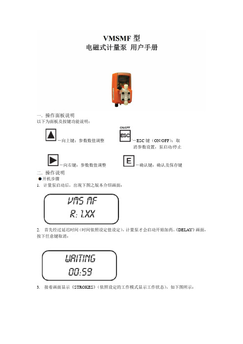
以下为面板及按键功能说明:消参数设置,泵启动/停止二.操作说明1.计量泵启动后,出现下图之版本介绍画面:2. 首先经过延迟时间(时间依照设定值设定),计量泵才会启动开始加药。
《DELAY》画面,按下任意键取消:3. 接着画面显示《STROKES》(依照设定的工作模式显示工作状态),如下图所示:启动/停止计量泵《ESC》键有两个功能,一是取消及放弃参数设置功能;二是作为计量泵的启动/关闭功能。
计量泵于《OFF》状态时,无法进入功能设置页面进行参数设置,如下图所示,按住《ESC》键(约3秒钟)启动计量泵;任何时间或任何设置页面按住《ESC》键(约3秒)可停止计量泵。
(OFF-停止,ON-启动)动作模式设置MODE-PROG[1]VMS MF型计量泵可工作于七种不同模式,分别为:CONSTANT/定量式、DIVIDE/脉冲分配式、MULTIPL Y/脉冲乘算式、PPM/百分比浓度控制式、BATCH/批量式、VOLT/电压控制式、mA/电流控制式。
我们的计量泵都是脉冲输出信号所以只需设置两个参数就可以实现计量泵的加药动作。
MULTIPLY/脉冲乘算式-MOD[03]接收脉冲水表或其他脉冲讯号来源,计量泵以倍数进行加药动作。
倍数最小值为1,错误的数值计量泵将不会储存。
若觉得加药太慢可以适当的增加倍数。
按《向上/向右》键修改参数值,按《E》键储存设置,按《ESC》键放弃修改或离开。
同时设置《DELAY TIME》(讯号周期时间),计量泵将自动把动作间隔平均分散于下一个脉冲讯号之前,请参考初始设置说明《DELAY-SET[05]》。
设置SETUP-PROG[2]除了动作模式设置之外,另外有参数需进行设置,由《MODE-PROG[2]》选单进入。
TIMEOUT/脉冲间隔时间-SET[05]此设置仅对《MULTIPL Y》(脉冲乘算式)动作模式有效。
当计量泵接收到水表的讯号后就开始动作,动作时间为第一个脉冲至下一个脉冲的时间段。
计量泵选型及使用说明

计量泵选型及使用说明一、计量泵综述1.1计量泵的基本工作原理计量泵主要由动力驱动、流体输送和调节控制三部分组成。
按其动力驱动和流体输送方式的不同,计量泵可以大致划分成柱塞式和隔膜式两大类。
⏹隔膜式计量泵隔膜式计量泵利用特殊设计加工的柔性隔膜取代活塞,在驱动机构作用下实现往复运动,完成吸入---排出过程。
由于隔膜的隔离作用,在结构上真正实现了被计量流体与驱动润滑机构之间的隔离。
隔膜式计量泵中,液压驱动式隔膜泵采用液压油均匀地驱动隔膜,克服了机械直接驱动方式下隔膜受力过分集中的缺点,提升了隔膜寿命和工作压力上限。
隔膜式计量泵中,电磁驱动式计量泵以电磁铁产生脉动驱动力,省却了电机和变速机构,使得系统小巧紧凑,是小量程低压计量泵的重要分支。
⏹柱塞式计量泵主要有普通有阀泵和无阀泵两种。
柱塞式计量泵因其结构简单和耐高温高压等优点而被广泛使用。
因被计量介质和泵内润滑剂之间无法实现完全隔离这一结构性缺点,柱塞式计量泵在高防污染要求流体计量应用中受到诸多限制。
1.2 计量泵的控制方式计量泵每一次的流体泵出量决定了其计量容量。
在一定的有效隔膜面积下,泵输出流体的体积流量正比于冲程长度L和冲程频率F:V∝A*F*L在介质和工作压力确定的情况下,通过调节冲程长度L和冲程频率F即可实现对计量泵输出的双维调节。
尽管冲程长度和频率都可以作为调节变量,但在工程应用中一般将冲程长度视为粗调变量,冲程频率为细调变量;调节冲程长度至一定值,然后通过改变其频率实现精细调节。
增加调节的灵活性。
在相对简单的应用场合,亦可手动设置冲程长度,仅将冲程频率作为调节变量,从而简化系统配置。
⏹常规开关量或模拟量信号调节方式过程控制应用中广泛采用0/4-20mA模拟电流信号作为传感器、控制器和执行器之间的信号交换的标准,具有外控功能的计量泵主要采用这种方式,实现对冲程长度和冲程频率的外部调节。
位置式伺服机构是实现冲程长度调节的普遍方法。
一体式的伺服机构被设计成能够直接接受来自调节器和计算机的0/4-20mA控制信号,从而自动调节冲程长度在0-100%范围内变化。
计量泵培训知识 课件

能正常工作
或安全放气阀
排出压力不 1.阀口卡有异物
1.清洗阀和阀座
稳定
2.出口管道有渗漏
2.排出渗漏
3.液体内有空气
3.排出液体内空气
4.安全放气阀或补油阀失 4.调整或更换安全放
灵
ppt课件
气阀和补油阀 46
让我们共同努力 共创德慧美好的明天
ppt课件
47
谢谢
ppt课件
48
ppt课件
6
气动计量泵
ppt课件
7
电磁计量泵
ppt课件
8
电动计量泵
ppt课件
9
计量泵发展历史
我国是随着七十年代大型化工装置的引进开始研发计 量泵
由于受日本的影响较大, 我们的最初设计基本仿照日 本
我国最先试制并形成规模的企业是重庆水泵厂、本溪 水泵厂。
ppt课件
10
计量泵发展历史
1936年由美国米顿罗公司发明了第一台计量泵 1939年美国帕斯菲达公司成立, 发明了第一台液压隔膜计
ppt课件
34
计量泵行程调节机构类型
1.N型曲轴调节机构 2.L型曲轴调节机构 3.弓形凸轮调节机构 4.弹簧凸轮调节机构 5.改变蜗轮倾斜角调节机构 6.改变连杆支点调节机构 7.滑轴斜槽调节机构
ppt课件
35
N形曲轴调节机构
ppt课件
36
泵的订货
订货时应填写“计量泵数据表”或者注明性能参数(流量、 压力、介质名称、粘度、温度、腐蚀性、是否有毒有害、 是否易燃易爆)现场条件(室内室外、环境温度、大气压 力)
ppt课件
31
调节行程为50%时泵运转效果
ppt课件
32
调节行程为100%时泵运转效果
G系列M型隔膜计量泵操作规程
G系列M型隔膜计量泵操作规程概述本文档旨在为使用G系列M型隔膜计量泵的操作人员提供详细的操作规程,以确保安全、高效地使用计量泵。
计量泵介绍G系列M型隔膜计量泵是一种体积可调的计量泵,能够准确地测量和输送液体。
计量泵通过压缩隔膜的方式使液体流动,泵体和动力部件之间通过密封结构隔离,确保泵浆不会通过泵马达进入机体。
由于采用了隔膜传动原理,液体能在正压下输送,也能在负压下抽取。
操作流程1.安装计量泵1.1准备安装环境:根据泵体尺寸和重量,选择合理的安装位置,并清理出足够的空间。
1.2安装支架:在安装位置上建立牢固的支架或基础,使其能够承受泵体和配件的重量。
1.3安装管路系统:将各种管路系统根据需要连接到计量泵上。
L4相关检查:检查计量泵是否与所有管道接口匹配并安装正确。
检查各种管道和阀门是否正确安装并牢固固定,避免泵出现漏气以及其他意外。
2.上下料操作2.1上料操作:先关闭泵的阀门,然后打开液体容器上的进液阀门,将液体缓慢原则注入泵体内,然后把药罐阀门关闭。
2.2下料操作:注意关闭进液阀门,保持出液阀门处于一直打开状态,并使用压缩空气将泵内余液排出。
3.启动和停止3.1启动:关闭出液阀门,将泵接至电源并按下启动按钮,并打开调节气垫压力的阀门。
3.2停止:将所有的进液和出液阀门关闭,然后将泵的电源关闭。
4.故障处理4.1泵出现滴漏:检查密封环发挥卡口是否正确,如果泄漏未解决,则应更换新密封环。
4.2泵没有压力:检查调节气垫压力的阀门是否打开,并检查气垫压力是否调低。
4.3泵发出异常声音:确认泵内无异物卡住,并检查突然变化或漏气部位;如果数据有异常,则应及时上报厂家,并进行相应维修。
注意事项1.操作人员必须经过培训,具备使用计量泵的基本技能,并遵守计量泵的操作规程。
2.必须检查泵体和密封件,并根据工作环境及运行条件进行定期的维护工作。
3.在接触装置或对计量泵进行调整或清洗时,必须关闭所有的闸门,并断开电源。
计量泵使用说明书
J型系列计量泵使用说明书上海净合设备有限公司一、概述本系列计量泵(以下简称泵)适用于输送温度-300C-1000C,(保温型泵适用输送1000C-5000C贴度0.3-8/s的不含固态颗粒之腐蚀或非腐蚀液体)。
(特殊型泵适用输送含有少量固体颗粒,粒度在0.5mm以下的悬浮液体)。
根据需要可选用单缸或多缸,柱塞式或隔膜式,多缸计量泵可同时输送一种或多种液体。
手动调节的泵在最大工况下计量精度在士1%以内(10:1)。
泵的流量可在0-100%内进行无级调节,建议在流量的30%-100%内使用。
二、结构说明本系列计量泵分三种机座:小(JX)、中(JZ)、大(JD)。
泵由传动机构、液力端、托架、联轴器等主要部分组成。
小机座的传动机构采用弓形凸轮式;中、大机座的传动机构采用N型轴式,三种机座的液力端均有柱塞式、隔膜式、保温式。
根据需要,流量可实现手动和自动控制。
1、弓形凸轮式传动机构电动机通过蜗杆蜗轮带动偏心轴旋转,经过弓形架使十字头、柱塞作直线往复运动,调节手轮可改变调节螺杆与偏心轴之间的距离,两者之间的距离越小泵行程越大,反之则越小。
2、N形轴式传动机构电动机通过蜗杆蜗轮带动偏心块旋转,经过连杆使十字头、柱塞作直线往复运动,调节手轮经N型轴可调节偏心距,偏心距越大泵行程越大,反之泵行程越小。
3、液力端液力端是液体的输送部分,其结构有柱塞式、隔膜式二种。
根据输送介质的要求液力端可选用不同的材料,如定货时未注明材料,按4类材料制造。
表一:液缸中装有不锈钢制成的双层吸入和排出阀,或单层吸入排出阀。
柱塞处的密封是根据使用要求来选择结构和材料的,有方形、V形等结构;有填充四氟,碳素纤维等多种材料,密封性能可靠,使用寿命长。
(2)隔膜式液力端隔膜式液力端装有隔膜、补油阀组等。
隔膜可使液缸后部隔膜腔的油与输送的液体分开,确保输送的液体绝对不漏。
柱塞的往复运动使隔膜腔里的油压发生变化,推动隔膜做往复运动来改变液缸内的容积,使吸入阀和排出阀交替动作,进行输送液体。
潘克尔(Parker)V12型号水力泵与电动机系列用户操作手册说明书

Effective: October, 2011Supersedes: June, 2006Bulletin HY30-5506-M1/UKService ManualSeries V122Parker HannifinPump and Motor Division Trollhättan, SwedenService Manual Series V12HY30-5506-M1/UKList of contents PageSpecifications and cross section ...............................................................3Assembling shaft package ..................................................................4 - 5Assembling cylinder barrel, joint shaft and cover ......................................5Assembling control cover ..........................................................................6Assembling end cap .............................................................................7-10Assembling complete unit ..................................................................11-13End-cap location .....................................................................................14Parts specification and split view ......................................................15 - 19Seal kit specification ................................................................................20Test procedure .........................................................................................21Gauge and pilot ports AC and AH control ................................................22Gauge and pilot ports EO and EP control ...............................................23Gauge and pilot ports HO and HP control .. (24)Conversion factors1 kg = 2.2046 lb 1 N = 0.22481 lbf 1 bar = 14.504 psi1 l = 0.21997 UK gallon 1 l = 0.26417 US gallon 1 cm 3 = 0.061024 in 31 m = 3.2808 feet 1 mm = 0.03937 in 1 °C= 1.8°F + 32Offer of SalePlease contact your Parker representation for a detailed ”Offer of Sale”.FAILURE OR IMPROPER SELECTION OR IMPROPER USE OF THE PRODUCTS AND/OR SYSTEMS DESCRIBED HEREIN OR RELATED ITEMS CAN CAUSE DEATH, PERSONAL INJURY AND PROPERTY DAMAGE.This document and other information from Parker Hannifin Corporation, its subsidiaries and authorized distributors provide product and/or system options for further investigation by users having technical expertise. It is important that you analyze all aspects of your application, including consequences of any failure, and review the information concerning the product or sys-tem in the current product catalogue. Due to the variety of operating conditions and applications for these products or systems, the user, through its own analysis and testing, is solely responsible for making the final selection of the products and systems and assuring that all performance, safety and warning requirements of the application are met.The products described herein, including without limitation, product features, specifications, designs, availability and pricing, are subject to change by Parker Hannifin Corporation and its subsidiaries at any time without notice.WARNING!3Parker HannifinPump and Motor Division Trollhättan, SwedenService Manual Series V12HY30-5506-M1/UKSpecifications¹) Max 6 seconds in any one minute.1. End cap2. Servo control valve3. Setting piston4. Valve segment5. Cylinder barrel6. Spherical piston with laminated piston ring7. Synchronizing shaft8. Heavy-duty roller bearings9.Bearing housing10. Output shaftV12 cross section4Parker HannifinPump and Motor Division Trollhättan, SwedenService Manual Series V12HY30-5506-M1/UKAssembling, shaft package1. Press down the big tappered roller bearing and the inner ring for the roller bearing in two steps. Note! On V12-060 there is a distance between the bearings.2. Press down the roller bearing with the text upwards into the flange and assemble it on the shaft package.3. Assemble the bearing ring with the textdownwards.4. Assemble the shim.5. Assemble the retaining ring. Make sure it is all the way into the groove. Check the pre-load of the bearings, not to tight and no back-lash.6. Assemble the O-ring.5Parker HannifinPump and Motor Division Trollhättan, SwedenService Manual Series V12HY30-5506-M1/UK7. Press down the shafts seal in the seal car-rier and assemble the retaining ring.8. Assemble the seal carrier with shaft seal and the retaining ring. Make sure it is all the way into the groove.Assembling, shaft package, cylinder barrel, joint shaft and cover9. Assemble the guide pins.10. Assemble the sliding plate.11. Assemble the joint rollers on the joint shaft. Make sure the step on the joint rollersis fitted inwards.12. Assemble the displacement setting screw, seal nut and the O-ring.6Parker HannifinPump and Motor Division Trollhättan, SwedenService Manual Series V12HY30-5506-M1/UK13. Assemble the O-rings and plugs that are required for the specific control cover. AH-control is shown in the picture.14. Assemble the control piston in the AH- housing. 15. Assemble the O-ring.Assembling, control cover16. Assemble the hexagon plug.DIN 38±8 Nm SAE 25±5 NmDIN 13±3 Nm (AHI-I)DIN 38±8 Nm SAE 25±5 Nm17. Assemble the AH-housing. The narrowside against X5.12±3 NmNarrow side18. Put some greas on the guide pin and assemble it in the control cover.7Parker HannifinPump and Motor Division Trollhättan, SwedenService Manual Series V12HY30-5506-M1/UK19. Assemble the hexagon plugs.DIN 38±8 NmSAE 25±5 NmAssembling, end cap20. Assemble the adjusting screw and seal nut.21. Assemble the setting piston in the endcap. Make sure the thread is against the con-trol cover side.22. Assemble the companion pin in the set-ting piston. Make sure the location hole is against the control cover side.23. Assemble the set screw with the pointed end. Make sure that it hits the location hole inthe companion pin.24. Torque the set screw to 14±4 Nm.8Parker HannifinPump and Motor Division Trollhättan, SwedenService Manual Series V12HY30-5506-M1/UK25. Assemble the set screw with the flat end. 26. Torque the set screw to 26±6 Nm. Move the companion pin back and forward to make sure it moves smooth.27. Assemble the spring guide. Use a longallen key to locate the spring guide.28. Assemble the modulating spring.Assembling, end cap29. Assemble the spring seat.30. Assemble the threshold spring.9Parker HannifinPump and Motor Division Trollhättan, SwedenService Manual Series V12HY30-5506-M1/UK31. Assemble the spring seat.Assembling, end cap33. Assemble the valve sleeve assy. Make sure the spool hits the guide hole in thespring seat.34. Assemble the valve cones.35. Assemble the valve guides assy. Care-fully tap them down with a hammer.36. Assemble the nozzles and torque them to1,2±0,2 Nm.32. Assemble the nozzles and torque them to 1,2±0,2 Nm.10Parker HannifinPump and Motor Division Trollhättan, SwedenService Manual Series V12HY30-5506-M1/UK37. Assemble the control cover assy. Make sure the O-rings are in correct position.38. Torque the screws to 65±10 Nm forV12-60 -- 110, 105±20 Nm for V12-160.39. Assemble the cover assy. Make sure notto damage the O-ring.40. Torque the screws to 65±10 Nm forV12-60 -- 110, 105±20 Nm for V12-160.41. Assemble the valve segment in the end cap. The slot in the valve segment against the cover side.Assembling, end capAssembling, complete unit42. Place the bearing package in a fixture.Assemble the compression spring.43. Assemble the guide pin.44. Assemble the support pin.45. Assemble the pistons and line them up as shown in picture.46. Assemble the joint shaft with joint rollers. Add some grease to keep the joint rollers inplace.47. Assemble the support pin. Use a lot of grease to keep it in place.Assembling, complete unit48. Assemble the cylinder barrel. Make surethat all rollers are in place.49. Make sure the support pin is in correct position by using a steel wire.50. Assemble the gasket and lubricate it withhydraulic oil.51. Assemble the bearing housing. Carefully knock it down with a plastic hammer. Securethe housing by assembling one screw.52. Assemble the gasket and lubricate it withhydraulic oil.53. Assemble the end cap assy. Mind your fingers, don't squeeze them.Refer to page 14 for end cap location.Assembling, complete unit54. Assemble the screws and torque the screws to 65±10 Nm for V12-60/80 and 105±20 Nm for V12-110/160.55. Assemble the screws and torque the screws to 65±10 Nm for V12-60/80 and 105±20 Nm for V12-110/160.End cap locationAC and AH control shold be assembled with the con-trol cover at the maximum side.EO and EP control shold be assembled with the con-trol cover at the minimum side.HO and HP control shold be assembled with the con-trol cover at the minimum side.Minimum sidesidesideGeneral PartsItem Title Benämning111 End Cap Ansl. Block211 Bearing Housing Lagerhus225 O-Ring O-Ring227 Gasket Packning227 O-Ring O-Ring229 O-Ring O-Ring231 Seal Carrier Tätringshållare233 Shaft Seal Tätningsring237 Retaining Ring Spårring245 Seal Washer Tätbricka246 Hex Socket Screw Insexskruv311 Shaft Axel411 Cylinder Barrel Cylindertrumma 413 Guide Pin Styrstift415 Needle Bearing Nålbussning420 Valve Segment Ventilsegment424 Sliding Plate Glidplatta433 Compression Spring Tryckfjäder434 Guide Pin Styrpinne440 Piston Assy Kolv KPL447 Joint Shaft Synkroniseringsaxel 448 Joint Roller Rulle449 Support Pin Stödpinne451 Spring Pin Rörpinne453 Pin Pinne454 Retaining ring Spårring455 Joint Coupling Medbringare460 Tap Rol Bearing Kon Rullager465 Spacer Sleeve Distanshylsa470 Cyl Bearing Cyl Lager476 Spacer Washer Distansbricka476 Spacer Washer Distansbricka478 Retaining Ring Spårring493 Hex Socket Screw Insexskruv495 Gasket Packning501 Bearing Housing Lagerhus510 Hexagon Plug InsexproppSplit view493453451454227501510449448449495411415424413420455440434237225478476470465 (V12-60 only)460311433231233476246211229246245227447111General Parts End CapItem Title Benämning 111 End Cap Anslutningsblock 121 Cover Lock122 Set Screw Ställskruv 123 Seal Nut Tätmutter 125 O-RingO-Ring 126 Hex Socket Screw Insexskruv 133 Setting Piston Ställkolv 134 Set Screw Stoppskruv 135 Set ScrewStoppskruv136 Companion Pin Medbringartapp 822 Shuttle Spolkolv 823 WasherBricka824 Compression Spring Tryckfjäder 825 Hexagon Plug Sexkantpropp 835 NozzleMunstycke 841 Protective Cover Skyddslock 842 Hex Socket Screw Insexskruv 843 O-RingO-Ring844 Expanding PlugExpanderplugg111133822823824825835844843841842125121123122126844135134136Item Title Benämning 701 Nozzle Munstycke 703 Nozzle Munstycke 705 NozzleMunstycke 711 Control Cover Regulatorlock 719 O-Ring O-Ring720 Support Ring Stödring 729 O-Ring O-Ring 735 Valve Cone Ventilkägla 736 Valve GuideVentilsäte737 O-Ring with Support Ring O-Ring med Stödring 771 Valve Sleeve Ventilfoder 772 Valve Spool Ventilslid 774 Piston Ring Lamellring 775 O-RingO-Ring 781 Modulating Spring Tryckfjäder 782 Threshold Spring Tryckfjäder 783 Spring Seat Fjädersäte 784 Spring Seat Fjädersäte 785 Spring Guide Fjädersäte 791 Adjusting Screw Ställskruv 793Sealing NutTätmutter705791785781784782775783774701717771735736737711703729772720Assembled in the end cap719793General Parts Control743747741746742744Item Title741 AH Housing 742 O-Ring743 Hex S Screw 744 Control Piston 746 Piston Seal 747 Guide Pin761762763Item Title 761 Solenoid 762 O-Ring 763 Guide Pin726DIN: M14x1,5SAE: 9/16 - UNF-2B714713724723711722DIN and SAE: M10x1Item Title711 Control Cover 713 Set Screw 714 Seal Nut 722 Seal Plug723 Hexagon Plug 724 Hexagon Plug 726 Hexagon PlugGeneral Parts ControlsSeal Kit Specification495720775719717123125843729737746742762227224229225233229245227For N-type flangeV12-060 3794856V12-080 3794858V12-110 3795372V12-160 379638821Parker HannifinPump and Motor Division Trollhättan, SwedenService Manual Series V12HY30-5506-M1/UKTest procedureUse a test stand that supplies a flow of about 30 l/min. and pressures of up to 300 bar.A secondary flow of 3-5 l/min. at a pressure of 25 bar is required to supply low pressure for externally supplied controls.EP control requires an amplifier supplying correct current according to specification.Test1. Fill housing with hydraulic fluid and start the pump in the test stand.2. Increase the pressure with the restrictor valve on the return line. Max allowed pressure is 150 bar / 2150 psi.3. Check the drain flow and compare with the table.För funktionskontroll behövs en provbänk med kapacitet 30l/min och 300 bar. Ett sekundärflöde på 3-5 l/min och tryck 25 bar krävs för ställdon med extern matning.EP ställdon kräver en förstärkare.Test1. Fyll V12 med olja ihuset och starta pumpen i testbänken.2. Öka trycket med stryp-ventilen på returledningen. Trycket får inte överstiga 150 bar / 2150 psi.3. Mät läckflödet och kontrollera mot tabellenFunktionskontroll22Parker HannifinPump and Motor Division Trollhättan, SwedenService Manual Series V12HY30-5506-M1/UKGauge/Pilot ports (AC and AH control)X1 Setting piston pressure (increasing displ.)X2 Servo supply pressure (after orifice)X4 Servo supply pressure (before orifice)X5 External pilot pressure X6 Setting piston pressure (decreasing displ.)X7 Override pressure (only AH control)Ports are: - M14x1.5 (ISO and cartridge versions)- 9/16"-18 O-ring boss (SAE version)MaxMinX5Displacement(setting piston position)Override Min threshold Max pressureSystem pressurepressurepressureACE 01 I schematic (spool in a balanced, mid-pos.)MaxMinDisplacement(setting piston position)Max System pressurepressure23Parker HannifinPump and Motor Division Trollhättan, SwedenService Manual Series V12HY30-5506-M1/UKGauge/Pilot ports (EO and EP control)X1 Setting piston pressure (max-to-min, EO)X1 Setting piston pressure (decreasing displ. EP)X2 Servo supply pressure (after orifice)X4 Servo supply pressure (before orifice)X6 Setting piston pressure (min-to-max, EO)X6 Setting piston pressure (increasing displ. EP)Ports are: - M14x1.5 (ISO and cartridge versions)- 9/16"-18 O-ring boss (SAE version)Displacement(setting piston position)DisplacementSolenoid currentcurrent currentEPH 01 E schematic (spool in balanced, mid-pos.)24Parker HannifinPump and Motor Division Trollhättan, SwedenService Manual Series V12HY30-5506-M1/UKGauge/Pilot ports (HO and HP control)X1 Setting piston pressure (max-to-min, HO)X1 Setting piston pressure (decreasing displ. HP)X2 Servo supply pressure (after orifice)X4 Servo supply pressure (before orifice)X5 External pilot pressure (max 100 bar)X6 Setting piston pressure (min-to-max, HO)X6 Setting piston pressure (increasing displ. HP)Ports are: - M14x1.5 (ISO and cartridge versions)- 9/16"-18 O-ring boss (SAE version)MaxMinMaxMinDisplacement(setting piston position)Displacement(setting piston position)Min threshold pressureMax threshold pressurePilot pressureThreshold press. (min)Adjustment rangeP s HO S 01 E schematic (X5 not pressurized)P s Min threshold pressureMax threshold pressureΔp Threshold pressureModulating pressurePilot pressureHP S 01 I schematic (spool in a balanced, mid-pos.)HP S 01 E schematic (spool in a balanced, mid-pos.)25Parker HannifinPump and Motor Division Trollhättan, SwedenService Manual Series V12HY30-5506-M1/UK26Parker HannifinPump and Motor Division Trollhättan, SwedenService Manual Series V12HY30-5506-M1/UK27Parker HannifinPump and Motor Division Trollhättan, SwedenService Manual Series V12HY30-5506-M1/UKParker HannifinPump and Motor Division Flygmotorvägen 2SE-461 82 Trollhättan SwedenTel: +46 (0)520 40 45 00 Fax: +46 (0)520 371 05 。
计量泵使用说明

计量泵
多缸泵联数
表1 泵头过流部分主要材料代号表:
材料代号
I
III
IV
V
VB
VI
VII
VIII
IX
X
XII
XIV
材料牌号
45
2Cr13
1Cr18
Ni9Ti
1Cr18Ni
N12Mo2Ti
316L
PVC
Monel
Hasstelloy
B
1Cr18Ni
12Mo3Ti
Hasstelloy
C
TiA2
20号合金
计量泵使用说明
———————————————————————————————— 作者:
———————————————————————————————— 日期:
ﻩ
一.概述:2
1.简介:2
2.型号说明:2
3.泵的结构及工作原理:3
1).传动机座部件结构:3
2).行程调节机构及调量表的使用:3
3).泵头结构:ﻩ3
当调节转盘顺时针旋转时,小螺旋齿轮带动大螺旋齿轮、调节螺杆转动,拖动调节螺母和N形轴上下移动,改变了偏心距,从而达到流量调节的目的。当N形轴在下限位置时行程为0%,当N型轴在上限位置时行程为100%(见图2)。随着N形轴位置从下限向上限位置提升(调节),柱塞行程将从0~100%呈线性变化。调量表紧固在调节转盘内,当旋转调节转盘时,调量表上的长短二针借助重锤式差动轮系转动;表盘上的读数由内外两圈刻度组成,刻度均为100格;当外圈长针转动一圈时,内圈短针转动一格,短针所示刻度即为计量泵行程调节百分值。
表2 泵头特殊功能代号
字母代号
R0
R1(N)
Atlas Copco 迪浦泵指南说明书
A Focus-5 guide to help you decide what’s right for you!Dewatering pumps1. EfficiencyWhen users have to choose a pump, they usually opt for larger sizes on the basis that they can cover a multitude of jobs, but, in doing so, energy efficiency is often sacrificed. Developments in technology are helping to reduce fuel usage and operating costs. In recent years, newer types of pump have been introduced that are specifically designed to reduce fuel consumption at times of low load and cope with fluctuating application demands; without running up high-fuel costs or risking burnout. Therefore, it is recommended that buyers consider newer types of technology, rather than simply replicating orders from the past. Bigger is not always better!.2. Size and movementPumps are now being developed to be smaller and lighter, as well as easier to move and transport both on and between work sites. Consequently, buyers should take time to ensure they select a pump that is suitable for use on multiple sites where the pumps might be working, and include built-in features that enhance movement and safety. Many larger pumps have integrated trailer options, as well as integrated lifting beams and/or forklift slots. Buyers should ask what options the manufacturer has added to aid the safe movement of the pump from site to site, or within the working location where it is needed.3. VersatilityNo two jobs are ever the same. For this reason, it is recommended to choose a pump that is suitable for multiple applications. Taking a look at the design of the pump’s components and how they work together should therefore be a priority. Subsequently, users should consider pumps that come with:1. A range of accessories to enhanceperformance for changing applications. 2. A performance that covers multipleapplications and offers different options. 3. A modular design that enables upgrades orchanges to the existing pump, without theneed to replace it with a completely newone.4. DurabilityPumps need to perform reliably in extreme environments. Therefore, it is important the selected pump has been tested and is capable of withstanding tough and changeable working conditions as soon as it is turned on.In addition, pumps shouldn’t get clogged up. If a pump becomes clogged, then it will reduce the flow of water being pumped. When cloggingoccurs, it will affect performance, and if allowed to continue for an extended period of time the pump could ultimately burn out. It’s not very often that users are pumping perfectly cleanwater, so some elements of clogging are a hazard of the task. To protect against problems, leading manufacturers are continually looking at the positioning of parts and specifically the inletholes and passing areas. Before choosing a, users should ask what steps the manufacturer hastaken to avoid clogging and guarantee consistent performance.5. Ease of serviceDowntime is lost time. When it comes to pumping fluids, any time lost formaintenance and repairs can be catastrophic. It is recommended to choose pumps with acombination of long-service intervals and simple service. Furthermore, as every second counts in terms of operational time, it is suggested to seek pumps that can be serviced in minutes, not hours, with easy access to all parts and consumables. Often, service needs to be completed remotely or at a job site, so the availability and simplicity ofservice pack is a major consideration.Readers note:Many of the values shown are average values. Actual specifications of products offered may differ between manufacturers and geographic regions.Product portfolio*Multiple configurations available to produce power for any size applicationONLINE SOLUTIONSPORTABLE 1,6–12 kVAMOBILELARGE POWER 9–1250* kVA 800–1450 kVAINDUSTRIAL 10–2250* kVAGENERATORSSHOP ONLINE PARTS ONLINEPOWER CONNECT Find and order the spare parts for power equipment. We handle your orders 24 hours a day.Scan the QR code on your machine, and go to the QR Connect Portal to find all the information about your machine.ENERGY STORAGE SYSTEMZENERGIZEDIESELBATTERYELECTRICLIGHT TOWERSAIR COMPRESSORS AND HANDHELD TOOLSAIR COMPRESSORS HANDHELD TOOLS FLEETLINKIntelligent telematicssystem that helps optimize fleet usage and reduce maintenance, ultimately saving time and cutting operating costs.1–116 m³/min 7–345 barPneumatic HydraulicPetrol engine drivenDiesel and electric options availableDEWATERING PUMPSELECTRIC SUBMERSIBLE 250–16.200 l/min833–23.300 l/minSURFACE PUMPS LIGHT THE POWER YOUR SIZING TOOL A useful calculator to help you choose the best solution for your power and light needs2958 1570 00 © A t l a s C o p c o P o w e r a n d F l o w d i v i s i o n . 2020。
计量泵使用说明书
计量泵系列产品使用说明书上海哥尼流泵业有限公司注意:1、计量泵使用前请在齿轮箱内加220#蜗轮蜗杆油或50#齿轮油至油标,并在液压油池内加L-HM32-46液压油至油标。
2、计量泵电机接线一定要按照电机名牌的电压接线(380V或220V)。
3、计量泵开机之前一定要确保出口管道通畅(阀门全开)。
4、不锈钢管路接头焊接时,切不可把焊渣或杂物掉入管路或阀体内(从而造成计量泵不出水,压力变小或流量变小)。
5、出口管道压力一定要高于进口管路压力,如果低于进口压力,一定要加装背压阀,防止产生缸吸。
一、概述液压隔膜式计量泵常用单联的独立参数提供用户。
也可根据用户需要制造同机座同规格的多联组合或不同机座不同规格组合。
多联式适用于工艺流程中需多种介质的比例配送。
该泵可广泛用于石油、化工、纺织、食品、造纸、原子能技术、电厂、塑料、制药、水厂、环保等工业和科技部门。
用来向加压或常压容器及管道内精确定量输送不含固体颗粒的液体。
其流量可以开机(或定机)时从0—100%范围内无级调节。
(根据计量泵的特性,最少行程一般不小于总行程的10%)单缸泵适用于单一液体的场合;组合泵可作比例泵使用,也可并联使用;泵组合可作为三比例泵使用,也可三泵并联,以达到较大排量,增高了液体的脉冲频率,促使液体连续顺畅加入。
该型泵可输送温度-20—100℃,粘度为0.3—800mm2/s不含固体颗粒等腐蚀性或非腐蚀性液体介质。
不同型号的计量泵均可根据用户要求装配变频电机(能接收4—20mA电流信号)或防爆电机。
泵的型号规格及参数请参考本公司的产品样本。
液压隔膜式计量泵采用两种调节方式:一是改变泵的柱塞行程长度,可在停机或运行状态进行。
计量精度在±1%以内,用于手动调节的有调量表,千分尺来指示柱塞相对行程值。
三是采用变频电机与变频器组合,改变输入电源频率调节泵速,改变流量大小。
此方法适用于自动、遥控及计算机管理等调节方式(另见计量泵自动控制使用说明书)。
计量泵的操作及使用

计量泵操作及使用说明书第一节说明慨述MILROYAL B为往复式容积控制泵,依靠泵入口和出口的正压差输送给定体积的液体,输送量可以准确控制在设定量的1%内。
泵由三个主要部件组成:⑴驱动装臵,⑵往复活塞,⑶泵头(液端)。
泵的输出流量是驱动速度、活塞行程长度和活塞直径的函数。
而且,一个给定的输出量是可以通过对泵的行程长度(冲程)进行机械(微米手柄)或(备选)电动或气动调节进行改变,泵驱动可配臵填料柱塞(容积阀),圆隔膜或高性能隔膜(双隔膜)泵头。
本手册包含了机械调节驱动部分。
操作原理驱动装臵带动泵柱塞,吸入行程时将液体吸入泵头(液端),而在随后的排出行程时将液体排出,只有当排出压力大于吸入压力时,才能获得精确的流量控制。
MILROYAL B型泵独特的驱动机构是专利设计的曲柄原理,涡轮驱动曲柄使之在一个可变的平面上旋转,由于曲柄平面在垂直方向改变,因此通过曲柄与柱塞相连可获得往复运动。
通过从垂直位臵开始调节曲柄平面斜度可使泵的行程长度从零增至最大值。
随着柱塞在泵头往复运行,液体便交替的被吸入和排出,在泵的吸入行程(向后),柱塞在泵头腔产生一负压,吸入线上液体压力使吸入口止回阀球体离位,液体流入泵头腔,在排出行程中,柱塞向前移动,在液体上加压,使排出口止回阀球体离位而将液体排出。
在每个吸入行程,排出止回阀球就位,而在每个排出行程,吸入止回阀球就位(泵头压力大于吸入压力)。
这种操作方式的作用是阻止液体回流,并确保液体从吸入端通过泵头腔至排出端排出。
填料柱塞泵头,柱塞与输送液体相接触,而隔膜泵头则使输送液体与柱塞隔离。
在后者的设计中,柱塞移动液体,推动与输送液体相接触的隔膜,迫使输送液体通过泵头。
(隔膜泵头单独进行讲述。
)安全预防措施在安装、操作、维护MILROYAL B型泵时,应事先考虑各安全注意事项。
操作设备时,应使用适宜的工具、防护服和保护镜,安装设备时应注意确保操作安全。
遵守手册的说明,对不同的输送液体应采取适当的安全措施,对危险介质应小心(如腐蚀、有毒、溶剂、酸、碱、可燃物等)。
计量泵使用说明

计量泵使用说明————————————————————————————————作者:————————————————————————————————日期:ﻩ目录一. 概述: ................................................................................................................................................................. 21. 简介:.................................................................................................................................................... 22.型号说明:....................................................................................................................................... 23. 泵的结构及工作原理: (3)1).传动机座部件结构: (3)2).行程调节机构及调量表的使用: (3)3). 泵头结构:ﻩ34). 泵缸头工作原理: (3)5).隔膜泵补油系统:3ﻩ二.安装及配管:ﻩ41.开箱: (4)2. 安装:4ﻩ3.配管:4ﻩ1). 通则: (4)2). 户外安装: (4)3). 吸入管路:4ﻩ4). 排出管路: (4)5).典型管路系统配置:5ﻩ6). 电气连接:5ﻩ三、操作: (5)1. 启动前的准备工作:5ﻩ2. 初次启动:6ﻩ3.流量的校验与标定:6ﻩ4.填料的初始调节: (6)5.调量表的初始调节: (6)6.补油阀组的调节:7ﻩ1).安全自动补油阀组的调节:ﻩ72).限位补油阀的放气及安全阀调节: (7)7. 流量的远距离和自动控制: (7)8.隔膜破裂报警装置: ...................................................................................................................... 79.运行操作:ﻩ710.停泵:7ﻩ四、运行维护:8ﻩ1. 备件:ﻩ82.零部件备件订货应包含的信息:8ﻩ3. 常规的预防性维护:ﻩ81). 润滑油的更换:8ﻩ2). 填料的更换与跑合: (8)3).吸入、排出阀组的维护:ﻩ9五、泵的拆装顺序: ............................................................................................................................................. 91.柱塞计量泵泵头部件的拆卸: (9)2.隔膜计量泵泵头部件的拆卸: (9)3.传动箱部件的拆卸: ........................................................................................................................... 94.计量泵的装配: (9)六、使用中可能发生的故障、原因及排除方法:(见下表)10ﻩ一. 概述:1. 简介:J系列计量泵为往复式可变容积泵,在压差作用下,可用于输送特定体积的液体,无论泵工作或停机时,其流量均可调节,输送量可稳定控制在设定值的±1%以内。
apg利用说明书

1引言
1.1编写目的
3.5故障处置要求 ........................................................................................................................ 6
3.6其他专门要求 ........................................................................................................................ 7
4运行环境规定 ............................................................................................................................. 11
4.1设备...................................................................................................................................... 11
(2)游戏市场:此刻游戏种类千差万别,网络游戏、单机游戏层出不穷,但几乎没有以抗日为主题开发的,这是一个商机。
(3)咱们此刻是大三的学生,已经学习和正在学习一些相关知识,如软件工程、汇编、游戏开发等,应该有能力开发出一个简单的游戏。
计量泵使用说明书
计量泵系列产品使用说明书上海哥尼流泵业有限公司注意:1、计量泵使用前请在齿轮箱内加220#蜗轮蜗杆油或50#齿轮油至油标,并在液压油池内加L-HM32-46液压油至油标。
2、计量泵电机接线一定要按照电机名牌的电压接线(380V或220V)。
3、计量泵开机之前一定要确保出口管道通畅(阀门全开)。
4、不锈钢管路接头焊接时,切不可把焊渣或杂物掉入管路或阀体内(从而造成计量泵不出水,压力变小或流量变小)。
5、出口管道压力一定要高于进口管路压力,如果低于进口压力,一定要加装背压阀,防止产生缸吸。
一、概述液压隔膜式计量泵常用单联的独立参数提供用户。
也可根据用户需要制造同机座同规格的多联组合或不同机座不同规格组合。
多联式适用于工艺流程中需多种介质的比例配送。
该泵可广泛用于石油、化工、纺织、食品、造纸、原子能技术、电厂、塑料、制药、水厂、环保等工业和科技部门。
用来向加压或常压容器及管道内精确定量输送不含固体颗粒的液体。
其流量可以开机(或定机)时从0—100%范围内无级调节。
(根据计量泵的特性,最少行程一般不小于总行程的10%)单缸泵适用于单一液体的场合;组合泵可作比例泵使用,也可并联使用;泵组合可作为三比例泵使用,也可三泵并联,以达到较大排量,增高了液体的脉冲频率,促使液体连续顺畅加入。
该型泵可输送温度-20—100℃,粘度为0.3—800mm2/s不含固体颗粒等腐蚀性或非腐蚀性液体介质。
不同型号的计量泵均可根据用户要求装配变频电机(能接收4—20mA电流信号)或防爆电机。
泵的型号规格及参数请参考本公司的产品样本。
液压隔膜式计量泵采用两种调节方式:一是改变泵的柱塞行程长度,可在停机或运行状态进行。
计量精度在±1%以内,用于手动调节的有调量表,千分尺来指示柱塞相对行程值。
三是采用变频电机与变频器组合,改变输入电源频率调节泵速,改变流量大小。
此方法适用于自动、遥控及计算机管理等调节方式(另见计量泵自动控制使用说明书)。
- 1、下载文档前请自行甄别文档内容的完整性,平台不提供额外的编辑、内容补充、找答案等附加服务。
- 2、"仅部分预览"的文档,不可在线预览部分如存在完整性等问题,可反馈申请退款(可完整预览的文档不适用该条件!)。
- 3、如文档侵犯您的权益,请联系客服反馈,我们会尽快为您处理(人工客服工作时间:9:00-18:30)。
EM00136116
REV 1.2
目录
产品简介 .................................................... 1 控制面板..................................................... 3 标准材质..................................................... 4 注意事项..................................................... 4 接线......................................................... 5 管道连接..................................................... 5 安装......................................................... 6 启动......................................................... 8 安装尺寸..................................................... 8 故障原因及排除............................................... 9 使用注意事项................................................ 10
J4--J5
J4 和 J5 之间连接线圈的蓝线出 头,两出头之间不分正负
J3
J3 连接黄绿色的地线
EM00136116
REV 1.2
2
TEKNA EVO APG 控制面板
投药量按比例显示(4 个脉冲产生 1 个冲程)
功能键
投药量按比例显示(最大 1 个脉冲生 成一个冲程)
投药量按比例显示(10 个脉冲产生 1 个冲程)
电子连接
1
警报继电器
2
3 负极 4-20 mA 信号输入 4 正极 输入阻抗: 200ohm
5
6 输入频率信号,自由接触
7
(水表脉冲发生器)
8
变光开关
B
液位控制输入
REV 1.2
3
警报
显示
警报 LED
起因 液位报警停止
中断 补充流体
警报 LED
警报 LED 退出功能模式
4 0.42
5
0.52 4/6
160
6 0.63
8 0.83
7 0.36
10 0.52 4/6
300
15 0.78
18 0.94
20 1.11
25 1.39 8/12 300 40 2.22
54
3
本计量泵由两大部分组成,控制部分(内有电磁集成模块)和触液部分(与待加流 体接触)
EM00136116
REV 1.2
保修期限及范围
[1] 到货时,请确认所收的产品是否有破损的地方,附属品及备用品的数量是否齐 全,如在运送途中发生损坏,请依据保修规定立即联系我们。 [2] 自产品出厂之日起一年半为产品保修期。 [3] 在保修期内,用户正常使用条件下,如因设计和制造不当而导致的部件脱落或 缺陷,厂家将进行免费维修或更换。 [4] 以下情况下,用户须自行承担维修或更换的费用: 产品已过保修期 错误使用或存放 使用非厂家指定的,等级低劣的部件 非经厂家或厂家指定人员维修或改动而引起的损坏 因火灾、地震或其他自然灾害引起的损坏 [5] 厂家不承担任何因根据用户的标准、使用由用户指定的原料生产的产品的责 任。 [6] 厂家对因由所投流体引起的化学反应对产品的腐蚀或流体本身对产品的腐蚀不 承担任何责任,厂家根据用户的要求给出的产品选型,仅为推荐使用,不承担任何 使用后果。 [7] 故障或损坏原因应由用户和厂家服务工程师详细讨论后作出。 [8] 厂家不赔偿因产品使用过程中发生灾难而导致的不同的费用。
1
145
5
4
6 7
231
119
2
3 1
1 电源开关 2 调节部位 3 泵头 4 排气阀 5 排液管接头 6 吸液管接头 7 底座(可选)
触液端部分保证能与常用的大多数化学品兼容,鉴于市场上不同的化学品,我们建 议用户检验所投化学品与触液端材质是否相兼容。
线圈和电路板之间的接线图
J1--J2
J1 和 J2 之间连接线圈的黄线出 头,两接头之间不分正负
投药量乘法模式显示 (1 个脉冲产生 N 个 冲程)
比例或恒定模式投药双色显示(黄色为手动控制模式,绿色 为 4-20mA 信号控制模式)
流量百分比调节旋钮、脉冲比例调 节、乘法模式调节
液位探头、流量及记忆警 报显示
Байду номын сангаас
通过调节泵前部的频率调节旋钮(即:流量百分比调节 按钮)可以实现对流量的调节。
EM00136116
SEKO S.p.A Via Salaria,Km,92,200-02010 s.Rufina(RI)-ITALY Tel.+39 0746 60580-Fax+39 0746 607072-Internet:
APG 说明书
EM00136116
REV 1.2
感谢您购买 SEKO 计量泵,在安装和开始使用本设备之前,请仔细阅读本说明书, 未按照本说明书的要求操作而造成的任何损失,SEKO 公司将不承担任何责任。本说 明书中的内容,如有变动,恕不另行通知。
维修
产品在使用过程中,用户如发现异常,请立即停止产品运行,检查是否有部件工作 失灵(参照说明书) [1] 请联系厂家或经销商进行维修。 [2] 致电厂家或经销商要求维修前,请再次细读说明书,检查产品。 [3] 如需维修,请填写 seko《用户服务单》,以便提高维修效率:
1.型号及生产编号 2.产品工作环境及已使用年限 3.故障的详细情况 4.如需返回厂家维修时,请彻底清洗泵腔内的残余的流体
EM00136116
REV 1.2
产品简介
您选用的泵为下表所列泵家族中的一员:
型号 600 603 800 803
压力
bar
20 18 12 10 8 2 12 10 5 1 5 4 2 1
PVDF
流量
升/小 时
立方厘 米/冲
程
接头 (mm)
进/出口
冲程/ 分钟
2.5 0.35 4/6-4/7 120 3,0 0.41
