BFT电机控制板说明书
ABB 电机说明书
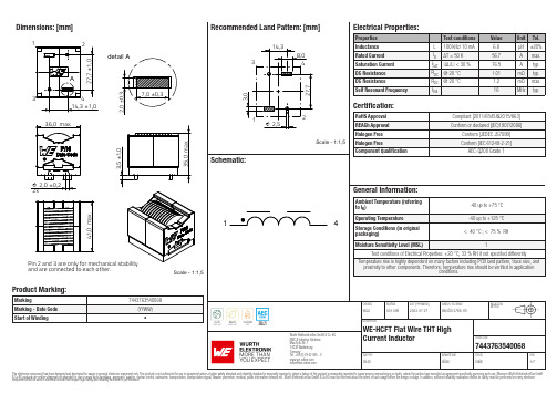
Dimensions: [mm]detail Aand are connected to each other.Scale - 1:1,57443763540068744376354006874437635400687443763540068T e m p e r a t u r eT T T 7443763540068Cautions and Warnings:The following conditions apply to all goods within the product series of WE-HCFT ofWürth Elektronik eiSos GmbH & Co. KG:General:•This electronic component is designed and manufactured for use in general electronic equipment.•Würth Elektronik must be asked for written approval (following the PPAP procedure) before incorporating the components into any equipment in fields such as military, aerospace, aviation, nuclear control, submarine, transportation (automotive control, train control, ship control), transportation signal, disaster prevention, medical, public information network, etc. where higher safety and reliability are especially required and/or if there is the possibility of direct damage or human injury.•Electronic components that will be used in safety-critical or high-reliability applications, should be pre-evaluated by the customer. •The component is designed and manufactured to be used within the datasheet specified values. If the usage and operation conditions specified in the datasheet are not met, the wire insulation may be damaged or dissolved.•Do not drop or impact the components, the component may be damaged.•Würth Elektronik products are qualified according to international standards, which are listed in each product reliability report. Würth Elektronik does not warrant any customer qualified product characteristics beyond Würth Elektroniks’ specifications, for its validity and sustainability over time.•The responsibility for the applicability of the customer specific products and use in a particular customer design is always within the authority of the customer. All technical specifications for standard products also apply to customer specific products.Product specific:Soldering:•The solder profile must comply with the technical product specifications. All other profiles will void the warranty.•All other soldering methods are at the customers’ own risk.Cleaning and Washing:•Washing agents used during the production to clean the customer application might damage or change the characteristics of the wire insulation, marking or plating. Washing agents may have a negative effect on the long-term functionality of the product. Potting:•If the product is potted in the customer application, the potting material might shrink or expand during and after hardening. Shrinking could lead to an incomplete seal, allowing contaminants into the core. Expansion could damage the component. We recommend a manual inspection after potting to avoid these effects.Storage Conditions:• A storage of Würth Elektronik products for longer than 12 months is not recommended. Within other effects, the terminals may suffer degradation, resulting in bad solderability. Therefore, all products shall be used within the period of 12 months based on the day of shipment.•Do not expose the components to direct sunlight.•The storage conditions in the original packaging are defined according to DIN EN 61760-2.•The storage conditions stated in the original packaging apply to the storage time and not to the transportation time of the components. Packaging:•The packaging specifications apply only to purchase orders comprising whole packaging units. If the ordered quantity exceeds or is lower than the specified packaging unit, packaging in accordance with the packaging specifications cannot be ensured. Handling:•Violation of the technical product specifications such as exceeding the nominal rated current will void the warranty.•Applying currents with audio-frequency signals may result in audible noise due to the magnetostrictive material properties.•Due to heavy weight of the components, strong forces and high accelerations may have the effect to damage the electrical connection or to harm the circuit board and will void the warranty.•The temperature rise of the component must be taken into consideration. The operating temperature is comprised of ambient temperature and temperature rise of the component.The operating temperature of the component shall not exceed the maximum temperature specified.These cautions and warnings comply with the state of the scientific and technical knowledge and are believed to be accurate and reliable.However, no responsibility is assumed for inaccuracies or incompleteness.Würth Elektronik eiSos GmbH & Co. KGEMC & Inductive SolutionsMax-Eyth-Str. 174638 WaldenburgGermanyCHECKED REVISION DATE (YYYY-MM-DD)GENERAL TOLERANCE PROJECTIONMETHODElGa001.0062023-07-27DIN ISO 2768-1mDESCRIPTIONWE-HCFT Flat Wire THT HighCurrent Inductor ORDER CODE7443763540068SIZE/TYPE BUSINESS UNIT STATUS PAGEImportant NotesThe following conditions apply to all goods within the product range of Würth Elektronik eiSos GmbH & Co. KG:1. General Customer ResponsibilitySome goods within the product range of Würth Elektronik eiSos GmbH & Co. KG contain statements regarding general suitability for certain application areas. These statements about suitability are based on our knowledge and experience of typical requirements concerning the areas, serve as general guidance and cannot be estimated as binding statements about the suitability for a customer application. The responsibility for the applicability and use in a particular customer design is always solely within the authority of the customer. Due to this fact it is up to the customer to evaluate, where appropriate to investigate and decide whether the device with the specific product characteristics described in the product specification is valid and suitable for the respective customer application or not.2. Customer Responsibility related to Specific, in particular Safety-Relevant ApplicationsIt has to be clearly pointed out that the possibility of a malfunction of electronic components or failure before the end of the usual lifetime cannot be completely eliminated in the current state of the art, even if the products are operated within the range of the specifications.In certain customer applications requiring a very high level of safety and especially in customer applications in which the malfunction or failure of an electronic component could endanger human life or health it must be ensured by most advanced technological aid of suitable design of the customer application that no injury or damage is caused to third parties in the event of malfunction or failure of an electronic component. Therefore, customer is cautioned to verify that data sheets are current before placing orders. The current data sheets can be downloaded at .3. Best Care and AttentionAny product-specific notes, cautions and warnings must be strictly observed. Any disregard will result in the loss of warranty.4. Customer Support for Product SpecificationsSome products within the product range may contain substances which are subject to restrictions in certain jurisdictions in order to serve specific technical requirements. Necessary information is available on request. In this case the field sales engineer or the internal sales person in charge should be contacted who will be happy to support in this matter.5. Product R&DDue to constant product improvement product specifications may change from time to time. As a standard reporting procedure of the Product Change Notification (PCN) according to the JEDEC-Standard inform about minor and major changes. In case of further queries regarding the PCN, the field sales engineer or the internal sales person in charge should be contacted. The basic responsibility of the customer as per Section 1 and 2 remains unaffected.6. Product Life CycleDue to technical progress and economical evaluation we also reserve the right to discontinue production and delivery of products. As a standard reporting procedure of the Product Termination Notification (PTN) according to the JEDEC-Standard we will inform at an early stage about inevitable product discontinuance. According to this we cannot guarantee that all products within our product range will always be available. Therefore it needs to be verified with the field sales engineer or the internal sales person in charge about the current product availability expectancy before or when the product for application design-in disposal is considered. The approach named above does not apply in the case of individual agreements deviating from the foregoing for customer-specific products.7. Property RightsAll the rights for contractual products produced by Würth Elektronik eiSos GmbH & Co. KG on the basis of ideas, development contracts as well as models or templates that are subject to copyright, patent or commercial protection supplied to the customer will remain with Würth Elektronik eiSos GmbH & Co. KG. Würth Elektronik eiSos GmbH & Co. KG does not warrant or represent that any license, either expressed or implied, is granted under any patent right, copyright, mask work right, or other intellectual property right relating to any combination, application, or process in which Würth Elektronik eiSos GmbH & Co. KG components or services are used.8. General Terms and ConditionsUnless otherwise agreed in individual contracts, all orders are subject to the current version of the “General Terms and Conditions of Würth Elektronik eiSos Group”, last version available at .Würth Elektronik eiSos GmbH & Co. KGEMC & Inductive SolutionsMax-Eyth-Str. 174638 WaldenburgGermanyCHECKED REVISION DATE (YYYY-MM-DD)GENERAL TOLERANCE PROJECTIONMETHODElGa001.0062023-07-27DIN ISO 2768-1mDESCRIPTIONWE-HCFT Flat Wire THT HighCurrent Inductor ORDER CODE7443763540068SIZE/TYPE BUSINESS UNIT STATUS PAGE。
Eaton XT电机控制器系列产品说明说明书

Win-win with push-in: XT motor controlEaton’s XT motor control now offers push-in technology. This new tool-free connection technology makes wiring even faster, safer, more efficient and reliable. The XT motor control solution with push-in technology offers maximum reliability, can be used anywhere in the world, and integrates seamlessly into existing control panel designs.No screws needed—just one clickThe push-in terminals enable safe and easycontrol-panel wiring with just one click with ferrule. Or if you’re not using ferrule wires, it’s still quick and easy to connect without using the screw. With our modular system and wide range of accessories, you’ll always find the right solution for your application.Because of their compact, space-saving size, these devices can be easily integrated into existing control cabinet designs.XT motor control, the win-win effectFaster, more cost-effective and reliable at the same timeFuture-proof your control panel the simple way Technicians and purchasers alike benefit from Eaton’s push-in range of devices. Eaton’s tried and tested XT motor control and state-of-the-art push-in technology makes wiring more efficient and reliable. Y ou too can benefit from this win-win effect by future-proofing your control panel the simple way.C frame contactors B frame manual motor protectorsB frame contactor andcontactor relays2EATON XT contactors and manual motor protectors with push-in technologyXT motor control overview3EATON XT contactors and manual motor protectors with push-in technologySystem expansion with push-in technologySimplify and optimize the installation and design of your machines and systems by using Eaton’s tool-free push-in technology, which is suitable for use without restrictions anywhere in the world.With the simplified wiring process, establishing the connection is up to 50% faster (compared to screw terminals), thereby increasing the competitiveness of your products.ote: N Secure connections can still be made without a ferrule by simply using a screwdriver to help the wire slide into place.XT contactorsThe XT contactors are powerful, efficient and versatile and can be combined with Eaton’s entire product range. The XT contactors are suitable for global use and cover the entire output range, from mini contactor relays (up to 7 A) to vacuum contactors (up to 3180 A).Eaton has extended the rated current of the contactors with push-in connection technology to 38 A (AC-3).Through the expansion of our product range and the use of the new push-in technology, we’ve made wiring even easier, faster, safer and more reliable.Protecting and switching IE3 motorsThe latest update of the Energy-related Products (ErP) Directiverequires increasingly energy-efficient electric motors, with important implications for their design and protection systems. Eaton’s contactors, motor-protective circuit breakers and motor-starter combinations meet the challenges associated with protecting and switching IE3 motors.More features, same frame widthThe base unit of the contactors with screw technology from our XT family previously contained either an NC or NO auxiliary contact. The contactors with push-in technology are now equipped with two auxiliary contacts (1NC contact and 1NO contact) as standard. Thefootprint, however, remains the same.Faster commissioning• Tool-free and simplified installation•Time savings of 50% compared to screw terminalsImproved machines and systems•High level of vibration and shock resistance, i.e., no need to retighten the cable connections after transport; immediately ready for use •Maintenance-free over the entire service lifeA future-proof wiring system• Using the next generation of cage clamp terminals •Can be automatically installed by robots and robotic technologyEasy integration• No need to adapt the control panel design •Screw/push-in combination device for use with a three-phase bus bar link4EATON XT contactors and manual motor protectors with push-in technologyA11351321A22461422Existing accessories can simply be re-used The existing XT accessories can be easily connected to the new, screw-free devices.Energy savings made easy with the integrated suppressor circuitThe suppressor circuit is already integrated in every DC-operated contactor from Eaton. The contactors can be controlled directly from a PLC.C u r r e n t I (A )Time t (ms)5010015020025030000,10,20,30,40,50,6New contactor, same dimensionsThe new XT contactors with push-in technology have the same footprint as the contactors with conventional screw terminals and can therefore easily be installed in existing systems. This also simplifies the planning of new systems, as thedimensions are identical.68 mm85 mm45 mm 45 mmA1A2-+DC / PLC controlledIntegrated suppressor circuit5EATON XT contactors and manual motor protectors with push-in technologyXT manual motor protectorsEaton’s fuseless motor-protective circuit breakers combineshort-circuit and overload protection in a single device. Withintegrated electronic wide-range protection, the XTPE is able tocover the current range from 0.3 A to 32 A with only four types,which saves storage space and simplifies project planning. The 13different models of the electromechanical XTPR cover the currentrange from 0.1 A to 32 A.The motor-protective circuit breakers are fully compatible withEaton’s XT contactor series and are ideally suited for use inmotor-starter combinations. All accessories, including the integrated auxiliary contact switches, trip indicators, voltage releases and door coupling rotary handles, can be used.Suitable for motor-starter combinations• Wiring kits for motor starters up to 32 A• Mechanical connecting element• Pre-assembled connecting cablesIntegration into existing control panel designsfor global export—Eaton makes it possibleEaton’s push-in range boasts a winning combinationmodel that integrates both screw and push-inconnection in a single device. This means that thenew devices can also be easily incorporated intoexisting control panel designs.6EATON XT contactors and manual motor protectors with push-in technologySystem overview41. XTPR motor-protective circuit breaker up to 32 A—screw terminal2. XTPR motor-protective circuit breaker up to 16 A—screw/push-in terminal3. XTPR motor-protective circuit breaker up to 32 A—screw/push-in terminal4. XTPR motor-protective circuit breaker up to 32 A—push-in terminal5. XTPE motor-protective circuit breaker / circuit breakerup to 32 A—push-in terminal6. Undervoltage / shunt release—push-in terminal7. I EC/UL T power supply terminal for three-phasebus bar link—screw terminal8. T hree-phase bus bar link—screw terminal9. XTPR…-PI phase isolator / UL Type E andType F applications10. Trip indicator for overload and short circuit—push-in terminal11. Side-mounting auxiliary contact—push-in terminal12. Overload relay module—screw terminal13. Modbus T RTU networking module for XTPE14. SmartWire-DT T networking module for XTPE15. Door-coupling rotary handle16. F ront-mounting auxiliary contact—push-in terminal17. Mechanical connection module for motor starters18. X TRE contactor relay / XTCE contactors up to 7.5 kW—push-in terminal19. XTCE contactor up to 18.5 kW—push-in terminal20. Side-mounting auxiliary contact—push-in terminal21. Coil protection circuits22. SmartWire-DT networking module23. Electronic timer module—screw terminal24. Front-mounting auxiliary contact, four-pole—push-in terminal25. Front-mounting auxiliary contact, two-pole—push-in terminal26. Adapter for motor-protective circuit breakers/motor starters7 EATON XT contactors and manual motor protectors with push-in technologyAt Eaton, we believe that power is a fundamental part of just about everything people do. Technology, transportation, energy and infrastructure—these are things the world relies on every day. That’s why Eaton is dedicated to helping our customers find new ways to manage electrical, hydraulic and mechanical power more efficiently, safely and sustainably. To improve people’s lives, the communities where we live and work, and the planet our future generations depend upon. Because that’s what really matters. And we’re here to make sure it works.See more at /whatmattersWe make what matters work.*Follow us on social media to get the latest product and support information.Eaton is a registered trademark. All other trademarks are property of their respective owners.Eaton1000 Eaton Boulevard Cleveland, OH 44122United States © 2023 EatonAll Rights Reserved Printed in USAPublication No. BR034015EN / Z27662August 2023。
[信息与通信]BPBT英威腾变频器说明书
![[信息与通信]BPBT英威腾变频器说明书](https://img.taocdn.com/s3/m/597d7e3aec630b1c59eef8c75fbfc77da26997ff.png)
BPBT系列隔爆型变频调速器使用说明书徐州市坤仕华科技有限公司徐州英威腾电气设备有限公司目录安全注意事项 (3)1、概况 (4)1.1变频器的综合技术特性 (4)1.2分类和命名 (4)2、开箱检查 (5)3、拆卸和安装 (6)3.1变频器运行的环境条件 (6)4、接线 (7)4.1接线端子图 (7)4.2标准接线图 (8)4.3主回路的连接 (8)4.4控制回路的连接 (9)4.5符合EMC要求的安装指导 (10)5、操作 (11)5.1操作面板说明 (11)5.2操作流程 (13)5.3运行状态 (15)5.4快速调试 (15)6、详细功能说明 (16)P0组基本功能组 (16)P1组起停控制组 (19)P2组电机参数组 (21)P3组矢量控制参数 (22)P4组V/F控制参数 (23)P5组输入端子组 (25)P6组输出端子组 (29)P7组人机界面组 (31)P8组增强功能组 (33)P9组PID控制组 (38)PA组保护参数组 (40)PB组串行通讯组 (42)PC组补充功能组 (43)PD组厂家功能组 (44)7、故障检查与排除 (44)7.1故障信息及排除方法 (44)7.2常见故障及其处理方法 (45)8、保养和维护 (45)8.1日常维护 (46)8.2定期维护 (46)8.3变频器易损件更换 (46)8.4变频器的保修 (46)9、通讯协议 (46)9.1协议内容 (46)9.2应用方式 (46)9.3总线结构 (46)9.4协议说明 (47)9.5通讯帧结构 (47)9.6命令码及通讯数据描述 (48)附表:功能参数简表 (56)安全注意事项安装、运行、维护或检查之前要认真阅读本说明书。
说明书中有关安全运行的注意事项分类成“警告”或“当心”。
警告指出潜在的危险情况,如果不避免,可能会导致人身伤亡。
当心指出潜在的危险情况,如果不避免,可能会导致人身轻度或中度的伤害和设备损坏。
电机使用说明书

电机使用说明书Operating Manual概述本说明书适用于我公司生产的YX3、YET、Y2、YVP、YD系列低压三相异步电动机及其派生系列产品OverviewThe manual serves YX3、YET、Y2、YVP、YD Series low voltage asynchronous motors and it's derivative products as well.开始使用Putting into use (starting)收货检查Reception check收到电机后立即检查是否有损坏,如发现请立即拨打电话:0086-21-6463-1777,或发传真至0086-21-6463-7180,检查铭牌数据特别是额定电压、接线方式(星形或三角形)是否与合同订货要求相符,用手转动电机轴检查轴转动是否灵活。
Immediately check the motor for external damage upon receipt and if found, please inform us by telephone or fax without delay (Tel:0086-21-6463-1777, Fax:0086-21-6463-7180). Check all rating plate data, especially voltage and winding connection (star or delta). Turn shaft by hand to check for free rotation.绝缘电阻检查Insulation resistance check在电机调试前或怀疑线圈受潮时要测量电机的绝缘电阻,在25℃时的绝缘电阻值应超过以下表达式的值,表达式中:Measure the motor's insulation resistance before commissioning or when winding dampness is suspected. insulation Resistance, measured at 25°C, shall exceed the following reference value, i.e. where:R:单位兆欧(用500V绝缘电阻表测量)Array U表示电压,单位VP表示功率,单位kWR: MΩ( measured with 500 V dc Megger )U = voltage, Volts;P = output power, kW.警告:测量完绝缘电阻后应立即将测量线从电机上断开,以免线圈再次受到高电压冲击。
BFT 开门机LIBRA C LX
-8-
安装手册
综合信息 所提供的LIBRA-C-LX控制板都经过标准的出厂设置.任何设置选择可. 以通过相应的编程显示屏或通过掌上编程器来设置.控制板通过EEL- -INK协议支持 它的主要特色: - 2个Lux BT或Lux G BT马达的控制
-1-
Achtung! Bitte lesen Sie
安装手册
LLIBBRRAA-C-C-L-XLX
控制单元
D811589 00100_01 22-01-09
027908 3 4 7 1 9 0
8
-2-
D811589 00100_01
D811589 00100_01
快速安装
布线 A
220
B
0,75
3/23/EEC及以后的修订本.对于所有非欧共体国家,为达到良好的 拆解
安全水平,应当执行上述标准及该国的现行国家标准。
警告!此项操作只可以由有资格的人员进行。
- 本公司拒绝对因在建筑关闭结构(门、大门等)时未遵守良好的技 若拆解自动化系统是为了将它在另一处重新再装配起来,按照以下
进行:
- 安装过程必须符合欧洲标准89/336/CEE、72/23/EEC、98/37/EEC及 - 切断电源和整个外部电器装置。
13
6
C
27
5
15
4
3
12
2
11
1 Bar 1
2-BAR
13
6
15
5
28
4
3
12
2
11
1 Bar 2
3-BAR
13
6
D
27
5
15
4
3
12
ABB 2QD0325V33-QSFA IGBT驱动器说明书

• 2通道IGBT 驱动器• 设计紧凑,尺寸为68mm*99.5mm • 电源电压输入宽范围+14V~+30V• 光纤接口输入/输出• 集成副边电源欠压保护(UVLO)• 集成VCE 短路保护• 集成有源钳位•绝缘电压高达8000V特征描述典型应用机械尺寸机械尺寸图:参见第10页2QD0325V33-QSFA 是一款适配IGBT 模块的紧凑型2通道高绝缘等级的驱动器,针对高可靠性的大功率中压领域设计而成。
2QD0325V33-QSFA 适用于ABB 5SND 0500N330300或中车时代半导体TIM500GDM33-PSA011模块搭建的多种拓扑方案。
• 风力发电• 光伏发电• 中压变流器• 电机传动• 牵引传动该图片仅供参考,请以实物为准。
原理框图2QD0325V33-QSFA DriverIGBT Module型号定义参数绝对限值供电电源环境温度T=25℃,除非另有说明。
输出环境温度T =25℃,除非另有说明。
保护环境温度T A =25℃,除非另有说明。
时序环境温度T=25℃,除非另有说明。
安全和抗干扰环境温度T=25℃,除非另有说明。
特性曲线图1 负载门极电荷vs开关频率图2 短路保护响应时间vs母线电压图3 驱动功率vs工作温度副边电源监控副边电压在负载超载情况下,会发生电压下降。
当副边电压VISO(VISO 至COM)下降至欠压保护阈值V UVR ,将启动副边欠压保护。
副边欠压保护首先会将本通道驱动锁定在关断状态,确保对应IGBT 关断。
另一通道不会受影响,仍能正常开关,其对应的SO 信号为正常状态。
控制系统需要及时检测SO 信号,并根据策略发出系统闭锁命令。
副边电压保护逻辑关系(如图5所示)。
功能描述电源及电源监控这款驱动器配有隔离DC/DC 电源,可实现电源和门极驱动电路的电气隔离,基本原理框图(如图4所示)。
驱动器的原边及两个通道的副边都分别配备有电源监控电路,并实施欠压保护。
FCT使用说明
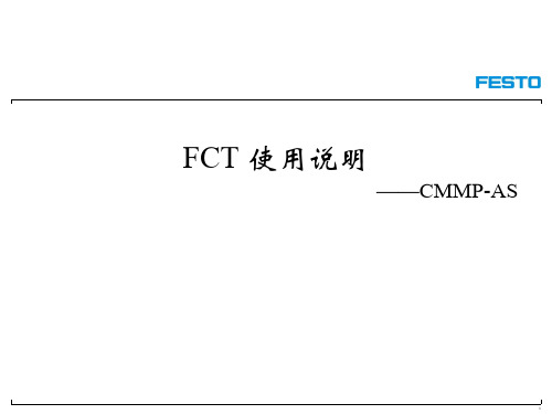
29
循环动作 方法1:Record Sequence
30
① 点击FCT,切换到MEM ② 动作开始条件,其中默认为Ignore,Delay为本次动作开始之前延时一段时间,延 时的时间长短由5设定。 ③ 触发顺序动作模式,GOFP1代表本次动作完成之后,立即进入Next1指定的位置 记录。 ④ 指定本次动作完成之后跳转到的位置记录。 设定完成之后,下载到控制器,点击前面的黄色按钮,即可实现预期动作。 1 2 3 4 5
16
寻零方式介绍
限位开关寻零 用于电缸、直线驱动轴的寻零
参考开关寻零 用于输送带、旋转驱动器的寻零
挡块寻零:检测电流是否到达设定 值确定零位。 没有限位开关寻零安全,不推荐
当前位置寻零:把当前位置作为零位
17
寻零方式附加选项
默认设置
寻零超时或超距设置
Next
18
软件最大/小值设置
默认设置
用来防止误设 位置对执行器 造成破坏。
FCT 使用说明
——CMMP-AS
1
硬件准备 软件初始设置 利用FCT寻零 利用FCT定位 利用手控盒寻零和定位 循环动作 利用模拟量输入设置定位点 数据记录功能
2
X1
X5
COM
电源
X6 X2B X9
动力电缆 编码器电缆
CMMP
X2A X10 X11
安全停车(默认) CAN
24
FCT软件下方有功能指示区,可以监测执行器位置、速度,以及电机电流、电压和 温度等信息。 注:这里实时监测值更新慢,可用Trace Data功能实时记录。 使能、停止、准 备、动作完成、 错误、警告信息 位置、速度以及 电流、电压等实 时信息 寻零可用、 限位开关 状态指示 IO状态指示
步进电机控制器--说明书

电机,伺服电机可编程控制器AKS-01Z使用说明一、系统特点●控制轴数:单轴;●指令特点:任意可编程(可实现各种复杂运行:定位控制和非定位控制);●最高输出频率:40KHz(特别适合控制细分驱动器);●输出频率分辨率:1Hz;●编程条数:99条;输入/1234、5、6一表示按键。
后面板图及信号说明:后面板图为接线端子,包括:1、CP、CW、OPTP为步进电机驱动器控制线,此三端分别连至驱动器的相应端,其中:CP————步进脉冲信号CW————电机转向电平信号OPTO————前两路信号的公共阳端CP、CW的状态分别对应面板上的指示灯2、启动:启动程序自动运行,相当于面板上的启动键。
3、停止:暂停正在运行的程序,相当于面板上的停止键,再次启动后,程序继续运行。
4、A操作和B操作是本控制器的一大特点:对于步进电机,我们一般进行定量定位控制,如控制电机以一定的速度运行一定的位移这种方式很容易解决,只需把速度量和位移量编程即可。
但还有相当多的控制是不能事先定位的,例如控制步进电机从起始点开始朝一方向运行,直到碰到一行程开关后停止,当然再反向运行回到起始点。
再例如要求步进电机在两个行程开关之间往复运行n次,等等。
在这些操作中,我们事先并不知道步进电机的位移量的具体值,又应当如何编程呢?本控制器利用:“中断操作”,我们称之为“A操作”和“B操作”。
以“A操作”为例,工作流程为:当程序在运行时,如果“A操作”又信号输入,电机作降速停止,程序在此中断,程序记住了中断处的座标,程序跳转到“A操作”入口地址所指定的程序处运行程序。
5、输入1和输入2通过开关量输入端。
6、输出1、输出2和输出3通过开关量输出端。
7、C OM+、COM—输入输出开关量外部电源,本电源为DC12V/0.3A,COM+为正端,COM—为负端,此电源由控制器内部隔离提供。
8、成后按参数分两行显示,第一行显示参数的名称,第二行显示参数数据。
参数修改方式:进入参数设定状态后,首先显示第一行[JF-------]。
BFT控制器、CLONIX或ECOSOL接收器设备用户手册说明书

Q.BO TOUCH QUICK START GUIDE1111OK X X X X OK 1111ON(Default code for channel 1)On CLONIX or ECOSOL receivers, press the RADIO LEARN button.On BFT Controllers with built-in receivers press:Press the O N button at the T-Box and wait 5 seconds.ONPress and HOLD the O N button until the red LED lights up.PressON STEP 1STEP 2STEP 3STEP 4Press and HOLD the O N button until the red LED lights up.PressPress PressON STEP 1(Default code for channel 1)(New code for channel 1)XXXXOK(New code for channel 1)STEP 2STEP 31234OK X X X X OK Press and HOLD the O N button until the red LED lights up.PressPress Press PressON STEP 1(Default programming passcode)(Existing code for channel 1)N N N N OK (New code for channel 1)STEP 2STEP 3NNNNOK(New code for channel 1)STEP 4PROGRAMMING THE T-BOX TO THE RECEIVERCHANGING THE DEFAULT CODEADDING CODES TO A CHANNELGUIA RAPIDA PARA Q.BO TOUCH1111OK X X X X OK 1111ON(Codigo de fabrica del canal 1)En los receptores CLONIX y ECOSOL oprima el boton de programaciónEn los controladores BFT con receptor integrado oprima:Oprima el botón de O N y espere 5 segundos.ONOprima y SOSTENGA el botón de O N hasta que el LED rojo se ilumine.OprimaONSTEP 1PASO 2PASO 3PASO 4Oprima y SOSTENGA el botón de O N hasta que el LED rojo se ilumine.OprimaOprima OprimaON PASO 1(Codigo de fabrica del canal 1)(Nuevo codigo para el canal 1)XXXXOK(Nuevo codigo para el canal 1)PASO 2PASO 31234OK X X X X OK Oprima y SOSTENGA el botón de O N hasta que el LED rojo se ilumine.OprimaOprima Oprima OprimaON PASO 1(Codigo de programacion de fabrica)(Codigo existente para el canal 1)N N N N OK (Nuevo codigo para el canal 1)PASO 2PASO 3NNNNOK(Nuevo codigo para el canal 1)PASO 4PROGRAMAR T-BOX A RECEPTORCAMBIAR EL CODIGO DEL CANAL 1AÑADIR CODIGOS AL CANAL。
I.L. 13016A Types BF 和 BFD 控制继电器及配件说明说明书
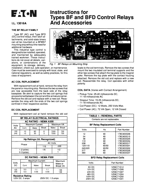
Instructions forI.L. 13016ATypes BF and BFD Control Relays And AccessoriesTHE BF RELAY FAMILYType BF (AC) and Type BFD (DC)control relays, their latch attachments, and solid-state timers can all be mounted on a BFMS7mounting strip without the need for additional hardware.This industrial type control is designed to be i nstalled, operated, and maintained by adequately trained workmen. These instructions do not cover all details, variations, or combinations of theequipment, its storage, delivery,Fig. 1 BF Relays on Mounting Strip installation, check-out, safe operation, or maintenance.leads to the coil terminals. Remove the two screws that Care must be exercised to comply with local, state, andmount the two insulated coil terminal supports and the national regulations, as well as safety practices, for thisother two screws that attach the top plate to the magnet class of equipment.yoke. Remove the top plate with the contact housing AC COIL REPLACEMENTWith replacement coil at hand, remove the relay from the panel or mounting strip. Remove the two screws thatare now accessible from the back side of the relaybaseplate. Be alert to capture the two coil springs that are positioned between the coil and the armature carrier. Remove the old coil and replace with a new coil. Reassemble the relay with the ends of the two coil springsconfined in their respective cavities.DC COIL REPLACEMENTWith replacement coil at hand remove the old coilBF RELAY ELECTRICAL RATINGSAC RATING-NEMA A300VoltsMaximum CurrentMaximum VAAC Cont.Make BreakMakeBreak120 10 60 6 7200 720 24010 30 3 7200 720Hp Ratings (UL Recognized)Phase AC Volts 115 230 1 (2 poles) 1/61/2 3 (3 poles)..1DC RATING -NEMA P300Maximum CurrentMaximum Volts Make or DC Cont.Make BreakBreak VA 125 5.0 1.1 1.1 138 2505.0 0.55 0.55138Resistive Rating125V DC: 3 amps250V DC: 1.5 ampsattached. Remove the old coil and replace with a new coil. Reassemble the relay. Coil operates with either polarity.COIL DATA (Varies with Contact Arrangement) •Pickup Time: 25-40 milliseconds DC;11-18 milliseconds AC •Dropout Time: 15-25 milliseconds DC;11-18 milliseconds AC •Coil Power (DC): 12 Watts, 250 Volts Max.•Coil Power (AC): 72 VA Open, 12 VA Closed TABLE 1-RENEWAL PARTSContacts are not replaceable.BF Relay Replacement CoilsVolts HzPart Number 12 60 178C603G06 24 60 178C603G15 48 60 178C603G05 110 60 178C603G54 208 60 178C603G17 120/110 60/50 178C603G01 240/220 60/50 178C603G02 277 60 178C603G26 48060178C603G07BFD Relay Replacement CoilsVolts Part Number 6V-DC 1259C71G12 12V-DC 1259C71G06 24V-DC 1259C71G07 48V-DC 1259C71G04 120V-DC 1259C71G02 240V-DC1259C71G01TYPES BF AND BFD CONTROL RELAYS I.L. 13016ABF Relay With Permanent Magnet Latch andSolid-State Timer BFD Relay With SolidState TimerBF Mounting StripDimensions, InchesiiDIOl'Nterl\1QU{'T1nqH01e$�II" ,.11l l1I a□a 1No of Dimension A Dimen11on8 Oimen11onC D1men11onO Dimension EPoln BF Only BF With Latch BF With Timer BFOOnly BFD With Timer• 3/n 6/u 51/, 4/u 711,,8 711,, 61/, 4111n 812 41:l/11 7111,, 1½ 5¾ 82'1n Fig. 2 Outline and Dimension Drawings {dimensions in inches).170 Dia.(2 Holes3 Slots)Fig. 3 BF Relay BaseplatePlace device so thatsteel hooks e ngage b ottom of relay base plate.1 "/2•"Insert screw driver insquare opening onmo unting strip abovethe re lay.ACCESSORIESSolid-state timersand magnetic latchattachments areavailable for directmounting on TypeBF and Type BFDrelays. See Table II.BSTD solid-statetimers can switch at24, 48 or 120 voe.A twist of the screwdriver forces the deviceint o p lace. T o r emovedevice, insert screwdriver be low the relayand reverse theproce dure.Fig. 4 Installation of BF Relay on Mounting StripEffective 4/90Supersedes 13016 (8/62). . 'TABLE IIType BST, BSTD Solid-State Timers On DelayVoltage Time DelayRangeCatalogNumber CD 120AC . 1 to 30 seconds BST-ON 120AC 30 to 60 seconds BST-ONB DC .1 to 30 seconds BSTD-ON Off DelayVoltage Time Delay CatalogRange Number CD 120AC .1 to 30 seconds BST-OF 120AC 30 to 60 seconds BST-OFB DC .1 to 30 seconds BSTD-OF G) For pan el mount version,add Suttix P tocatalog number.Type BFML Permanent Magnet Latch For AC RelaysCoil Coil CatalogVolts Hz Number24 60 BFMLI4860 BFMLJ 120/110 60/50 BFMLF 240/220 60/50 BFMLG For DC RelaysCoil CatalogVolts Number24 BFMLL48 BFMLM120 BFMLS240 BFMLT Mounting Strip for BF and BFDN o. of CatalogRelays Number7 BFMS7Printed in USA Powering Business Worldwide。
电机控制器操作手册说明书

GridPointEC Motor ControllerOperation ManualTWIN CITY FAN COMPANIES, LTD. | 5959 TRENTON LANE N. | MINNEAPOLIS, MN | 763-551-7600Instructions 1. Fan must be running when the controller is used.2. Turn the controller on and plug it into the motor. It will automatically connect.3. The display will show the current speed. Power, Connect and Direction LEDs will be on.4. If the Up arrow is pressed, the display will show E000 (no error), max speed, constant speed, d000 (direction) and C000 (motor operation mode 0).5. To set the maximum speed:a. Press ‘SET’ for 2s.b. Press the Up or Down arrow to display P000.c. Press ‘OK’. This will display the current maximum speed.d. Press the Up or Down arrow to change the digit. To move to the next digit, press and hold the Up arrow until the next digit flashes. Keep changing values until the desired speed is reached.e. Press ‘OK’ to save the value. Press ‘OK’ again to go back to the first display.Troubleshooting Guidelines Cannot connect to motor: Check the cord and connections between the controller and the motor.Motor does not run in Constant speed mode (P008 = 0): Update the value in parameter P001.Motor does not run in 0-10V mode: Check the voltage supply.Unable to change screens: Cycle power on GridPoint.Wheel rotation is incorrect: Contact TCFC Customer Service Department for support.Safety Precautions When operating GridPoint, please keep a safe distance from the fan. Maintenance and repair work should be carried out by trainedprofessionals.Parameters P001 and P008 are not read by the controller and default to ‘0’ when turned on. If the ‘M’ button is pushed without updating these values, the motor will be set at constant speed, 0 RPM.WARNING: Motor is still energized at constant speed, 0 RPM.f. Press ‘O’ for 2s to send the command to the motor.6. To set the speed for Constant speed operation:a. Press ‘SET’ for 2s.b. Press Up or Down arrow to select P001.c. Press ‘OK’. The default value is ‘0’. Change to desired speed by following steps 5d and 5e.d. Press ‘M’ for 2s to send the command to the motor.7. To set motor operation mode:a. Press ‘SET’ for 2s.b. Press the Up or Down arrow to display P008.c. Press ‘OK’.d. Arrow Up or Down to select desired mode. (See Parameters section above for functionality.)e. Press ‘OK’ to save the value.f.Press ‘M’ for 2s to send the command to the motor.RPM Top Speed 200 RPM 00.8V 9.6V 10V VOLTAGESmart EC Motors Grid Smart。
四方综保电动机说明书
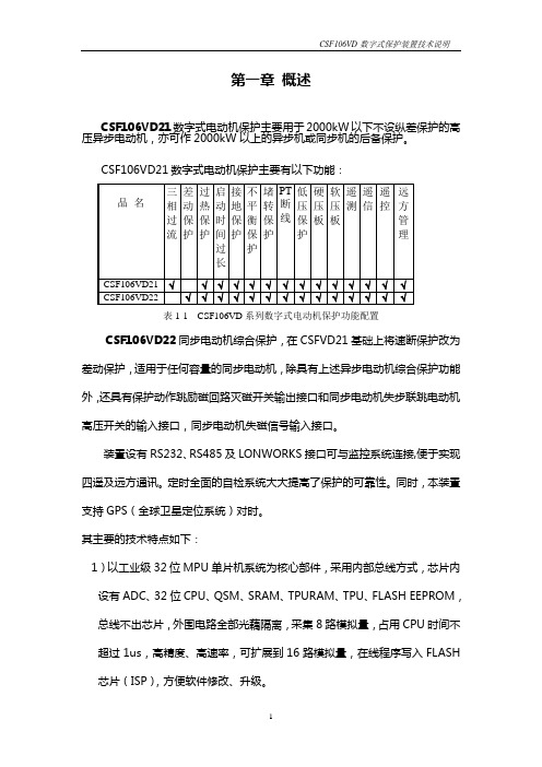
第一章概述CSF106VD21数字式电动机保护主要用于2000kW以下不设纵差保护的高压异步电动机,亦可作2000kW以上的异步机或同步机的后备保护。
表1-1 CSF106VD系列数字式电动机保护功能配置CSF106VD22同步电动机综合保护,在CSFVD21基础上将速断保护改为差动保护,适用于任何容量的同步电动机,除具有上述异步电动机综合保护功能外,还具有保护动作跳励磁回路灭磁开关输出接口和同步电动机失步联跳电动机高压开关的输入接口,同步电动机失磁信号输入接口。
装置设有RS232、RS485及LONWORKS接口可与监控系统连接,便于实现四遥及远方通讯。
定时全面的自检系统大大提高了保护的可靠性。
同时,本装置支持GPS(全球卫星定位系统)对时。
其主要的技术特点如下:1)以工业级32位MPU单片机系统为核心部件,采用内部总线方式,芯片内设有ADC、32位CPU、QSM、SRAM、TPURAM、TPU、FLASH EEPROM,总线不出芯片,外围电路全部光藕隔离,采集8路模拟量,占用CPU时间不超过1us,高精度、高速率,可扩展到16路模拟量,在线程序写入FLASH芯片(ISP),方便软件修改、升级。
2)128×64点大液晶全汉字显示,调试全部为汉字菜单结构,使用方便、直观、信息详尽丰富。
3)采用工业级芯片,表面贴工艺,体积小,抗震、抗干扰能力强、可靠性高。
4)前面板232串口带光电隔离,可在现场实现通讯,提供更加方便友好的调试操作环境。
5)结构上设计合理,全封闭机箱坚固、抗震、抗干扰能力强,机箱小巧,适合安装于保护屏、开关柜等处。
6)该保护共可录入4套保护定值,便于现场运行。
7)可扩展工业级CAN总线,LON总线网络,组网方便、经济、可靠、可与监控系统直接通讯。
8)自动记录故障数据,掉电不丢失,便于事故分析。
9)线路故障时,除提供光报信号外,保护自动弹出全中文故障报告,直观明了,便于维护。
小型机器人4路电机控制单元说明书

4 ChannelMotor Control UnitDesigned originally for the Rover 5 chassis this driver PCB is ideal for any small robot using either Omni or Mecanum wheels.Current sensing for each motor allows the processor to determine if a motor has stalled or is under excessive load.Features include:•4x low resistance FET “H” bridges.•Each channel rated for 4A stall current.•Easy to use control logic.•Current monitoring for each channel.•Quadrature encoder mixing circuitry.Power connectors:The PCB has two power connectors. One is +5V for logic (Vcc) and one for the motor power supply.The motor power supply should not be connected without first connecting the +5V for logic. This device is rated for a maximum motor supply voltage of 12V. Exceeding this voltage may permanently damage the device.The encoder mixing circuit:Unlike most motor controllers this PCB includes 4 mixing circuits for use with up to 4 quadrature encoders. The mixing circuit takes the 2 inputs from a quadrature encoder and mixes them into a single output. Note that the interrupt output changes state when either input changes.This allows a single interrupt pin to monitor both inputs of a quadrature encoder. Because the interrupt output is twice the frequency of either input it also allows speed and distance to be measured with twice the resolution.Current output:Each channel has a current sensing circuit. The output of this circuit is approximately 1V for each amp the motor draws(5V maximum).This output can be connected directly to the analog input of any 5V micro controller.Control logic:The built in control logic allows each motor to be controlled by 2 pins. Driving the direction pin high or low will cause the motor to run forward or reverse. The PWM pin is used to control the motor speed. When this pin is low, the motor is off. When this pin is high the motor is at full power. To vary the speed of the motor this pin must be Pulse Width Modulated.Motor output:Each channel has a motor output socket. Connect any 4.5V –12V DC motor with a stall current of less than 4.5A to these pins. Exceeding 4.5A on these pins may permanently damage this device.。
BEDFORD变频器说明书

B801系列使用手册V1.4目录1、前言 (1)2、安全注意事项 (1)3、产品检查3.1检查步骤 (1)3.2型号说明 (1)4、安装4.1外型尺寸 (2)4.2使用环境 (2)4.3注意事项 (2)5、配线5.1基本接线图 (4)5.2操作注意 (5)6、数字操作器使用方法6.1显示器及操作键 (5)6.2操作键的使用 (5)7、测试运转 (6)7.1掌握一些相应的调节方法或许能让您获得更理想的使用效果 (6)7.2键盘操作模式 (6)7.3键盘操作正、反转模式 (7)7.4控制端子操作模式 (7)7.5参数恢复出厂设定值 (7)7.6参数修改后储存条件 (7)8、显示屏上的符号解释 (8)9、参数和数据表9.1参数一览表 (11)9.2参数说明 (13)10、故障指令及对策10.1故障发生时处理排除的注意事项 (18)10.2异常故障处理对策表 (18)10.3运转注意事项 (19)11、B801-200V系列标准规格 (20)12、B801-400V系列标准规格 (21)1、前言感谢您选用B801系列高性能变频器,使用前务必请认真阅读本说明书。
2、安全注意事项变频器是电力电子新产品,为了您的安全,本手册中有“危险”“注意”等符号是提醒您在搬运、安装、运转、检查变频器时的安全防范事项。
! 危险错误使用时,可能造成人员伤亡。
! 注意错误使用时,可能造成变频器或系统损坏。
3、产品检查3.1检查步骤•变频器是否符合所订购的型号与规格。
•检查在运输过程中,变频器是否因运送不慎造成损伤,若有损坏请勿接入电源。
•保修单编号是否与变频器一致。
当您发现有上述问题时,请立即通知有关销售商的业务人员。
3.2型号说明4、安装4.1外型尺寸4.2使用环境变频器安装的环境对变频器正常功能的发挥及其使用寿命有直接的影响,因此,变频器安装的环境必须符合下列条件:•周围温度:壁挂型,-10~45℃;柜内封闭型,-10~40℃。
ABB 电机系统操作指南说明书
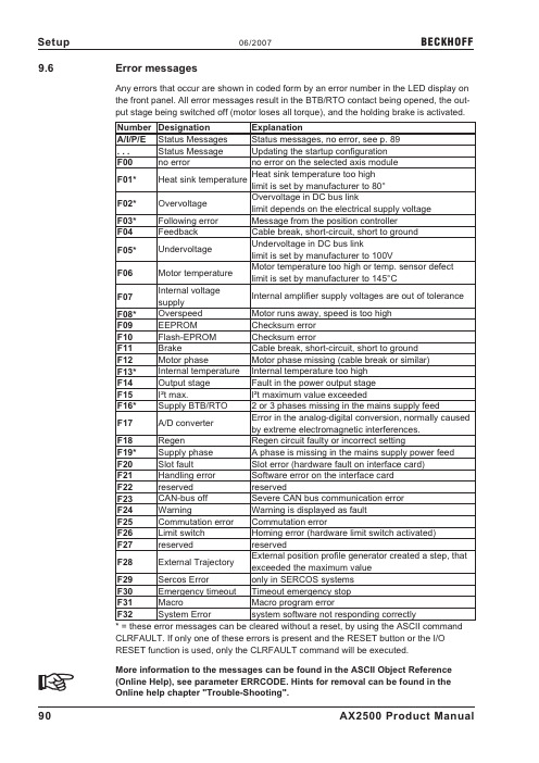
9.6Error messagesAny errors that occur are shown in coded form by an error number in the LED display onthe front panel.All error messages result in the BTB/RTO contact being opened,the out-put stage being switched off(motor loses all torque),and the holding brake is activated.Number Designation ExplanationA/I/P/E Status Messages Status messages,no error,see p.89...Status Message Updating the startup configurationF00no error no error on the selected axis moduleF01*Heat sink temperature Heat sink temperature too high limit is set by manufacturer to80°F02*Overvoltage Overvoltage in DC bus linklimit depends on the electrical supply voltageF03*Following error Message from the position controllerF04Feedback Cable break,short-circuit,short to groundF05*Undervoltage Undervoltage in DC bus linklimit is set by manufacturer to100VF06Motor temperature Motor temperature too high or temp.sensor defect limit is set by manufacturer to145°CF07Internal voltagesupplyInternal amplifier supply voltages are out of toleranceF08*Overspeed Motor runs away,speed is too highF09EEPROM Checksum errorF10Flash-EPROM Checksum errorF11Brake Cable break,short-circuit,short to groundF12Motor phase Motor phase missing(cable break or similar)F13*Internal temperature Internal temperature too highF14Output stage Fault in the power output stageF15I²t max.I²t maximum value exceededF16*Supply BTB/RTO2or3phases missing in the mains supply feedF17A/D converter Error in the analog-digital conversion,normally caused by extreme electromagnetic interferences.F18Regen Regen circuit faulty or incorrect settingF19*Supply phase A phase is missing in the mains supply power feed F20Slot fault Slot error(hardware fault on interface card)F21Handling error Software error on the interface cardF22reserved reservedF23CAN-bus off Severe CAN bus communication errorF24Warning Warning is displayed as faultF25Commutation error Commutation errorF26Limit switch Homing error(hardware limit switch activated)F27reserved reservedF28External Trajectory External position profile generator created a step,that exceeded the maximum valueF29Sercos Error only in SERCOS systemsF30Emergency timeout Timeout emergency stopF31Macro Macro program errorF32System Error system software not responding correctly*=these error messages can be cleared without a reset,by using the ASCII commandCLRFAULT.If only one of these errors is present and the RESET button or the I/ORESET function is used,only the CLRFAULT command will be executed.More information to the messages can be found in the ASCII Object Reference(Online Help),see parameter ERRCODE.Hints for removal can be found in theOnline help chapter"Trouble-Shooting".90AX2500Product Manual Setup06/2007BECKHOFF9.7Warning messagesFaults which occur,but which do not cause a switch-off of the amplifier output stage(BTB/RTO contact remains closed),are indicated in the LED display on the front panel bya coded warning number.Number Designation ExplanationA/I/P/E Status Messages Status messages,no error,see p.89...Status Message Updating the startup configurationn01I²t I²t threshold exceededn02Regen power Reached preset regen power limitn03*S_fault Exceeded preset following error limitn04*Response monitoring Response monitoring(fieldbus)has been activatedn05Supply phase Mains supply phase missingn06*SW limit switch1Underrun software limit switch1n07*SW limit switch2Overrun software limit switch2n08Motion task error A faulty motion task was startedn09No reference point No reference point(Home)set at start of motion taskn10*PSTOP PSTOP limit-switch activatedn11*NSTOP NSTOP limit-switch activatedn12Motor default valuesloadedOnly for ENDAT or HIPERFACE®:discrepancy between motor number saved in the en-coder and the amplifier,motor default values loadedn13*reserved reservedn14SinCos feedback SinCos commutation(wake&shake)not completed, will be canceled when amplifier is enabled and wake &shake carried outn15Table error Fault according to speed/current table INXMODE35 n16Summarized warning Summarized warning for n17to n31n17Fielbus Synchronization The mode synchronization SYNCSRC is selected but the drive isn’t in synchronies cyclen18Multiturn overrun Using Multiturn encoder feedback,an overrun over the maximum number of resolutions was detectedn19Motion task ramps arelimitedRange overflow on motion task datan20Wrong GMT data Wrong"Graphical Motion Task"data n21PLC program error For details see plc coden22max.motor temperaturreachedThe user can shut down the process before the tem-perature eror will interrupt the process immediatelyn23...n31reserved reservedn32firmware beta version Firmware is an unreleased beta version*=these warning messages result in a controller shut-down of the drive(braking byemergency stop ramp)More information to the messages can be found in the ASCII Object Reference(Online Help),see parameter STATCODE.Hints for removal can be found in theOnline help chapter"Trouble-Shooting".AX2500Product Manual91 BECKHOFF06/2007Setup。
博孚管状电机说明书

博孚管状电机说明书1. 引言博孚管状电机是一种创新的电动机技术,采用了管状结构和先进的控制系统,具有高效、轻量化和高性能的特点。
本说明书将详细介绍博孚管状电机的结构、工作原理、性能参数以及使用方法。
2. 结构介绍博孚管状电机由外壳、定子、转子和控制器组成。
2.1 外壳外壳是博孚管状电机的保护壳,采用高强度材料制成,具有良好的耐腐蚀性和防护性能。
外壳设计合理,便于安装和维修。
2.2 定子定子是博孚管状电机的固定部分,由多个线圈组成。
线圈通过导线连接到控制器,产生磁场。
2.3 转子转子是博孚管状电机的旋转部分,由多个永磁体组成。
永磁体产生一个稳定的磁场,并与定子产生相互作用,从而实现转动。
2.4 控制器控制器是博孚管状电机的核心部件,负责控制电机的启动、停止和转速调节等功能。
控制器采用先进的电子技术,具有高效、可靠和智能化的特点。
3. 工作原理博孚管状电机通过定子产生的磁场与转子上的永磁体相互作用,产生转矩,驱动转子旋转。
控制器根据输入信号控制定子线圈通电顺序和频率,从而实现对电机转速和方向的控制。
4. 性能参数博孚管状电机具有以下性能参数:•额定功率:XX W•额定电压:XX V•额定转速:XX rpm•最大扭矩:XX Nm•效率:XX%•质量:XX kg5. 使用方法5.1 安装安装博孚管状电机时,请按以下步骤进行:1.确保安装位置平整稳固。
2.将外壳固定在所需位置。
3.连接控制器与外壳。
4.将定子线圈连接到控制器。
5.安装转子。
5.2 启动与停止启动博孚管状电机时,请按以下步骤进行:1.检查电源是否正常。
2.打开控制器电源开关。
3.根据需要设置转速和方向。
4.按下启动按钮。
停止博孚管状电机时,请按以下步骤进行:1.松开启动按钮。
2.关闭控制器电源开关。
5.3 转速调节博孚管状电机可以通过控制器进行转速调节。
具体操作方法请参考控制器说明书。
6. 注意事项在使用博孚管状电机时,请注意以下事项:•请勿将电机暴露在潮湿、高温或腐蚀性环境中。
电力配电器产品信息:步进电机控制模块6DS1 411-8RR说明书

X73 1 2
Contact voltage E,S,26 and E,S,27 24 V
x
X26 1 2 X23 1 2
X73 3 4 X73 1 2
Contact voltage main contacts E,S,24 to E,S,33 48 V
X41 3 2 1 ***) X23 3 2 1
X26 1 X23 1
2 2 **)
X73 3 X73 1
4
Contact voltage main contacts E.S,24 to E, S 33
2 **) 24 V
X26 1 2 X23 1 2
X73 3 4
Contact voltage E,S,24; E,S,25; E,S,28 to 33 48V
TELEPERM ME Product Information 6DS1 411-8RR Step-action Controller Module, 2-channel Settings of module 6DS1 411-8RR which replaces 6DS1 411-8CC/DD/DE
***) The jumper at-8CC does not exist. Jumper X23 at -8RR has to be in the delivery state.
ã Siemens AG A5E00152201B.02
3/ 6
TELEPERM ME Product Information 6DS1 411-8RR Step-action Controller Module, 2-channel
X8 3
4
12 X8 3 4
X22 1 2 X22 1 2
BFT 维修
BFT 設備基礎與維修⏹有關BFT方面的基礎知識⏹BFT Fixture制作運行流程⏹BFT設備維修的基本理念&維修思路&方法⏹BFT設備維修實例分析MFG Testing Engineering DepatmentBY:luming.liaoSep .25 . 2003BFT 設備的基礎知識BFT設備的維修包括計算機,電子,電工和机械四方面.一.計算機方面包括計算機操作系統,軟件和計算機硬件方面的知識.1.計算機操作系統(OS):Dos的基本命令的運用,Windows 98,Windows2000,WindowsXP,Solaris(SUN Microsystems OS).Dos常見的基本命令運用dir 列出文件名和子目錄名清單/p 以一屏一屏地顯示/w 僅顯示文件名和子目錄名,不顯示文件其它信息/w/p 分屏顯示文件名和目錄名/a 顯示包括隱含文件和系統文件的所有文件/s 顯示指定目錄和子目錄下的文件md 建立子目錄如: c:\>md tempBFT 設備的基礎知識cd 顯示或改變當前目錄,“..”進入當前目錄的上一級子目錄,“\”返回到根目錄.如:c:\>c:\>cd tempfdisk 硬盤的分區format 格式化硬盤,“/ q”快速格式化(只清除FAT和根目錄區)diskcopy 同類型的磁盤整盤拷貝如: c:\>diskcopy a: a:copy 文件的拷貝“*”代表所有字符串,“?”代表一個字符﹒如: c:\>copy a:\*.* c:\temp 拷貝所有文件c:\> copy a:\*.bak d:\temp 拷貝以bak后綴名的所有文件Windows 操作系統的應用要熟練的掌握Windows 98 ,Windows 2000 ,windows XP 的一些基本知識,系統的安裝,驅動器的安裝和硬件的配置以及應用過程中所出現的問題的解決.BFT 設備的基礎知識Solaris 操作系統的基礎知識和基本命令對于Unix操作系統一般較為生疏﹒關于Unix系統﹐种類很多﹐因在維修Sun server 時有用到Solaris操作系統﹐簡單介紹一下SunMicrosystems 開發和發布的Solaris操作系統﹐其他暫且不講﹐Solarisy 運行的環境. 他是一個企業級操作環境,包含多處理、多用戶的Sun操作系統,最初只能運行在Sun SPARC (Scalable Processor Architecture ,可縮放處理機体系結构)的硬件上.最進,Sun推出了Solaris x86,可以運行在基于Intel的硬件之上﹒Solaris 特別適合在一個單獨的系統上支持數百個交互式用戶,也就是說,每一個用戶都可以使用在中央服務上執行的桌面上進行登錄.與其它操作系統相比,使用Solaris的好處通常在對稱多處理和多用戶環境中,盡管Microsoft Windows 也支持多個CPU,但是Solaris 最多可以支持64個CPU同時工作,其性能几乎以線性增長.而其他一些操作系統似乎是讓第二個、第三個或第四個CPU的大多數處理能力用于工作調度而不是用于操作.BFT 設備的基礎知識1).Solaris 操作系统与其它Unix系統一樣,主要由三个部分构成:KernelShellFile structure1)-1. Kernel 是操作系统的核心,它的主要功能是:管理系统的设备、内存、进程以及守护进程系统程序与系统硬件之间接口执行所有的命令管理:Swap space(交换分区)–系统运行时保留的一部分磁盘空间Daemons(守护进程)–处理特定的系统任务1)-2.shell是用户与kernel之间的接口它就像是命令的解释器或翻译器。
- 1、下载文档前请自行甄别文档内容的完整性,平台不提供额外的编辑、内容补充、找答案等附加服务。
- 2、"仅部分预览"的文档,不可在线预览部分如存在完整性等问题,可反馈申请退款(可完整预览的文档不适用该条件!)。
- 3、如文档侵犯您的权益,请联系客服反馈,我们会尽快为您处理(人工客服工作时间:9:00-18:30)。
天线安装 使用433MHz的天线。天线-接收器的连接,使用RG8同轴线。 金属物的接近会影响天线的接收。万一发射范围不够,可将天线移到更合适的位置。
6) 拨码开关设定(图 3) DIP1)TCA [ON] – 自动关门时间 TCA ON: 设定自动关门。 OFF:不使用自动关门。 DIP2)FCH [OFF] – 红外保护 ON: 仅在关门过程中起作用。如在关门过程中检测到障碍物,大门反转,执行开门指令。 OFF:在开/关门过程中都起作用。如检测到障碍物,大门停止动作。清除障碍物之后,大门继续原来的动作。 DIP3)BLI [OFF] – 阻止脉冲 ON: 开门过程中不接受START指令。 OFF:开门过程中接受START指令。 DIP4)3P/4P [OFF] – 3步骤/4步骤 ON: 3步骤逻辑;一个START(启动)脉冲执行步骤如下:
1) 总的安全规则 警告!安装错误或使用错误都会对人、宠物和物体带来严重危害。 警告!进行安装须使用符合 EN12978 规定的安全装置和控制。
请仔细阅读“警告”及“安装手册”,因为他们提供了关于安全,安装,操作及维护方面的重要信息。 拆掉符合目前规定的包装材料(塑料,纸板,泡沫等),避免儿童接触尼龙,发泡等。 保留此安装手册与技术材料,以备将来参考。 此产品专为本手册中指明用途所设计与制造,其它未列明使用将损坏该产品并造成危险。 本公司拒绝因未正确使用或未按本手册所列用途使用而导致后果的一切责任。 不要将本产品安装在易爆的空气中。 本产品所使用的安装配件必须符合以下欧洲标准:89/336/EEC,73/23/EEC, 98/37/EEC(及后来的修正),如 在没有欧洲标准的国家,该国家相应的质量标准也可以为产品提供一个安全的水平。 本公司拒绝因在建筑封闭建筑(门、大门等)时未遵守正确的技术惯例而导致的责任,同样也适用于使用时 可能造成的变形。 安装过程必须符合 89/336/EEC,72/23/EEC,98/37/EEC(及后来的修正内容)。 在执行任何安装过程的时候请不要接电源。 在总电源前安装一个多极或电磁开关,保持一个触点距离等于或超过 3.5mm。 检查是否已在电源主干线上装有一个 0.03A 的差动开关。 检查接地装置是否正确完成:把自动装置接地。 在可能发生碰撞等危险的区域安装安全保护装置(红外、电子边沿触发等),以确保安全。 至少安装一盏指示灯(闪灯)和一个明显的警示标志。 由于使用其他厂家的部件所造成的安全问题和运行效率下降,公司不承担任何责任。 在维护和维修时请使用原装配件,否则本公司将不负由于使用其它配件而导致的任何责任。 除非得到本公司的授权不要修改零部件。 指导使用人员关于该控制系统的信息以及手动开启的方法,以备紧急情况下使用。 不充许成人或儿童在电机的工作范围滞留。 请将遥控器或其他控制装置远离儿童,以避免无意的操作。 用户切勿尝试或执行操作维修,请向专业人员寻求帮助。 请不要做任何该手册上没有明确提示到的事情。 进行安装须使用符合 EN12978 规定的安全装置和控制。
5) LED(图 3) ALCOR N控制板提供了一系列自诊断功能的LED。 POWER:电源ON。 OP: 指示电机开启中/无线编程。 CL: 指示电机关闭中。 START:给出START指令时。 STOP: 熄灭时表示红外保护没有对准或有障碍物。
-3-
SWO: 输入13的状态:亮 – 输入闭合;熄灭 – 输入打开。 SWC: 输入14的状态:亮 – 输入闭合;熄灭 – 输入打开。
ALCOR N 使用说明
-1-
ALCOR N 使用手册
感谢您购买此产品,我们公司将确保您对此产品的性能满意。产品附带“警告”及“安装手册”。请仔细阅读此说 明书关于安全,安装,操作及维护方面的重要信息。此产品严格遵守已认证的技术标准和安全规则。我们声明该 产品满足以下欧洲标准:89/336/EEC ,73/23/EEC 和 98/37/EEC(及后来的修正内容)。
门关闭时:---------------------------------------开启 开门过程中:-------------------停止并执行TCA(如设定) 门开着时:---------------------------------------关闭 关门过程中:-------------------------------------开启 停止后:-----------------------------------------开启 OFF:4步骤逻辑;一个START(启动)脉冲执行步骤如下: 门关闭时:---------------------------------------开启 开门过程中:-------------------停止并执行TCA(如设定) 门开着时:---------------------------------------关闭 关门过程中:-------------------停止但不执行TCA(停止) 停止后:-----------------------------------------开启 DIP5)CODE FIX [OFF] – 固定码 ON: 设定内置接收器为固定码模式。 OFF:设定内置接收器为滚码模式。 DIP6)RADIO LEARN [OFF] – 无线学习 ON: 发射器通过无线存储: 1 – 选择通过无线菜单标准模式已设定的发射器;首先按隐藏键(P1),接着按发射器已设定的键(T1,T2, T3和T4)。 2 – 在10秒内按隐藏键(P1)和遥控器需要设置的按键(T1,T2,T3和T4)来储存信号。 10秒后接收器退出编程模式,其它新的发射器可以在这结束之前进行设定。 这种模式不需要进入控制板进行设定。 OFF:阻止遥控器通过无线存储。遥控器只能通过SW1和SW2设定(参见章节10)。 DIP7)LOCK HOLD [OFF] – 锁保持 ON: 如果电机在全开或全关位置超过1小时,向相应的方向运行3秒。每小时动作一次。 提示:目的在于补偿液压电机的油压,如夜间或内部泄漏。 重要 – 当没有安装机械门档时,不能使用该功能。也绝对不能使用在平移门电机上。 OFF:没有上述功能。 DIP8)RAW BLOW ON OPENING [OFF] – ON: 在开门之前,向关门方向运行大约2秒。使电锁更容易打开(不受限位开关的影响)。 OFF:关门时没有该功能。 重要 – 当没有安装机械门档时,不能使用该功能。也绝对不能使用在平移门电机。 DIP9)输入13-14限位开关/按钮功能选择
尺寸 ------------------------------------------------------------ 参见图1 (*根据需要可提供其它电压类型)
4) 端子排接线(图 2) 接线图和电线截面积大小,参见开门机安装手册。 警告 接线和安装时,请参考当前标准和技术惯例。不同电压等级的电线必须物理隔离,或之间至少有1mm额外的绝 缘层。靠近接线端子的电线必须用扎带固定。 黄绿线必须接地。230V电源线必须和低电压回路物理分隔。
-4-
ON: 输入13-14设定为按钮输入。输入13设定为开启指令,输入14根据DSW10的设定而定。这种方式下,电机的运 行时间决定于工作时间的设定
OFF:输入13-14设定为开门和关门限位开关输入。 DIP10)输入13-14限位开关/按钮功能选择* 提示:仅在DSW9设定为ON有效。如DSW9设定为OFF,则DSW10不起作用。 ON: 输入14设定为关门指令。 OFF:输入14设定为人行通道指令。 * 如果,该功能激活,关门限位开关不再有效,同时第一次动作时RAW BLOW功能和人行通道开启不会被执行。
7) TIMMER 调节(图3) TCA(DIP1 ON) 设定自动关门时间,到达时间之后,大门自动关闭(0-120秒可调)。 TW 设定电机工作时间,到达时间之后,电机停止运行(0-90秒可调)。如使用电子限位开关,在关门时间上增加几秒 作为电机工作时间。 DELAY M2 设定电机2(M2)关门延时时间(0-30秒可调)。
-2-
பைடு நூலகம்
内置滚码无线接收器 --------------------------------------- 频率 433.92MHz 学习码 ---------------------------------------------------------- 滚码 组合 ---------------------------------------------------------- 4 百万 天线 ---------------------------------------------------- 500hm(RG58) 最大发射器存储数目 ------------------------------------------------ 63
DSW9在OFF位置,输入信号为开启限位开关(N.C.),如不用,保留短接线。 DSW9在ON位置,输入信号为开启指令(N.O.)*。 9 -14 DSW9和DSW10功能选择: DSW9在OFF位置,输入信号为关闭限位开关(N.C.),如不用,保留短接线。 DSW9在ON位置,DSW10在OFF位置,输入信号为关闭指令(N.O.)*。 DSW9在ON位置,DSW10在ON位置,人行通道指令(N.O.)。 15-16 附件电源24V输出,最大200mA。 17-18 第二个无线通道输出,常开触点(24V/1A最大),如使用外接接收器,必须使用双通道接收器。连接常开 干触点到接线端子。 19-20 接收器天线输入(19 信号线,20 编织线)。 * 不使用限位开关时,电机的运行时间由设置的工作时间决定。 RX 外接接收器的接口。
警告!连接主电源,采用截面积不小于3×1.5mm2的多股线且须符合之前提到的标准。 例如:如果户外布线(不穿管),至少要使用H07RN-F的型号,如果室内布线(或户外但穿管),则至少要使用3x1.5mm2 的H05VV-F型号电缆。
