Cisco 数据中心之 HSRP, vPC 以及 vPC Peer-Gateway 介绍
思科数据中心虚拟化 vPC技术和配置
思科数据中心虚拟化vPC技术和配置最近在研究数据中心功能时发现CISCO有一个虚拟化技术叫vPC的技术,今天就把我研究的成果分享出来。
什么是 vPC(virtual port channel)?研究了大半天,其实它就是一个可以跨不同设备的port-channel技术。
它的作用:可以实现网络冗余,可以跨设备进行端口聚合,增加链路带宽,当链路故障时比生成树协议收敛时间还快。
下面我们就说说为什么会出现vPC技术。
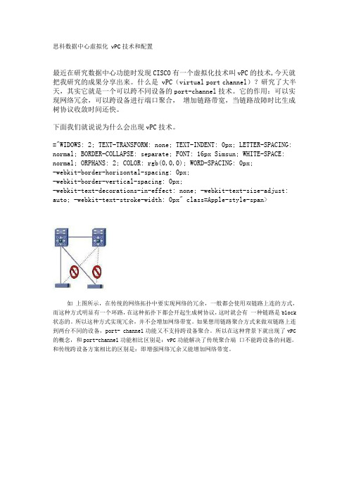
="WIDOWS: 2; TEXT-TRANSFORM: none; TEXT-INDENT: 0px; LETTER-SPACING: normal; BORDER-COLLAPSE: separate; FONT: 16px Simsun; WHITE-SPACE: normal; ORPHANS: 2; COLOR: rgb(0,0,0); WORD-SPACING: 0px;-webkit-border-horizontal-spacing: 0px;-webkit-border-vertical-spacing: 0px;-webkit-text-decorations-in-effect: none; -webkit-text-size-adjust: auto; -webkit-text-stroke-width: 0px" class=Apple-style-span>如上图所示,在传统的网络拓扑中要实现网络的冗余,一般都会使用双链路上连的方式,而这种方式明显有一个环路,在这种拓扑下都会开起生成树协议,这时就会有一种链路是block 状态的。
所以这种方式实现冗余,并不会增加网络带宽。
如果想用链路聚合方式来做双链路上连到两台不同的设备,port- channel功能又不支持跨设备聚合。
所以在这种背景下就出现了vPC 的概念,和port-channel功能相比区别是:vPC功能解决了传统聚合端口不能跨设备的问题。
热备份路由选择协议(HSRP)

热备份路由选择协 议原理
HSRP的配置及应 用
HSRP的相关概念 HSRP的状态
HSRP的计时器 HSRP与VRRP的区别
HSRP的配置 HSRP的应用案例 HSRP故障排查
4/34
HSRP的相关概念5-1
热备份路由选择协议
HSRP(Hot Standby Routing Protocol) Cisco私有协议
热备份路由选择协议(HSRP) —— 理论部分
ቤተ መጻሕፍቲ ባይዱ
课前小考
STP选举过程中,如何确定哪些端口被阻塞? 生成树端口状态有哪些,分别表示什么含义? HSRP占先权是什么?
2/34
理解HSRP的工作原理 掌握HSRP的术语和参数的作用 会HSRP的配置和排错
技能展示
3/34
本章结构
热备份路由选择协议 (HSRP)
小结
12/34
HSRP的配置4-1
配置为HSRP的成员
Switch(config-if)#standby group-number ip virtual-ip-address
配置HSRP的优先级
HSRP备份组 号
备份组虚拟IP地址
Switch(config-if)#standby group-number priority priority-value
路由器B 活备跃份路由器
互 联 网
15/34
HSRP的配置4-4
查看HSRP的状态
查看HSRP摘要信息
Switch#show standby [type mod/num] [group-number] brief
查看HSRP详细信息
Switch#show standby
双机热备技术:CISCO的HSRP配置解析
spanning-tree mode pvst spanning-tree vlan 100 priority 8192 spanning-tree vlan 200 priority 4096
解 析 :第 一 步 ,先 将 生 成 树 模 式 设 置 成 pvst即 每 个 vlan生 成 一 个 树 模 式 , 以使 交 换 机 能 够 提 供 负 载 均 衡 的 功 能 ;第 二 步 ,指 定 交 换 机 转 发 的 优 先 值 , 该 值 越 大 优 先 级 别 越 高 ; 第 三 步 , 为 了 使 vlan100的 数 据 均 由核 心 交 换 机 1转 发 ,使 vlan200 的 数 据 均 由 核 心 交 换 机 2转 发 ,设 置 vlan1O0 的 优 先 值 大 于 vlan200的 优 先 值 。这 三 条 命 令 就 完 成 了 负 载 均 衡 设 置 。
维普资讯
妨 ~
骷 一
J鼍i删
肛 ~
11 应 用 技 术
2007年 11月 10 13第 11期
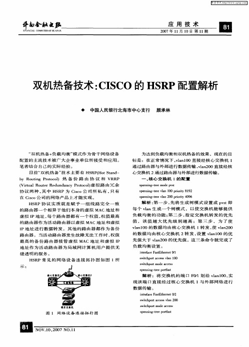
双机热备技术 :CISCo 的 HSRP配置解析
◆ 中国人 民银 行北 海市 中心 支行 颜 承林
“双 机 热 备 +负 载 均 衡 ”模 式 作 为 骨 干 网络 设 备 配 置 的 主 流 技 术 被 广 大 企 事 业 单 位 所 接 受 和 应 用 。 笔 者 结 合 自 己 的 实 际 经 验 。
HSRP协 议 实 质 就 是 赋 予 一 组 线 路 完 全 一 致 的 路 由 器 一 个 相 异 于 他 们 本 身 的 虚 拟 MAC地 址 和 虚 拟 IP地 址 ,每 个 路 由器 都 有 一 个 权 值 ,权 值 最 高 的 路 由 器 作 为 活 动 路 由 器 以 虚 拟 MAC地 址 和 虚 拟 IP地 址 进 行 数 据 转 发 ,其 他 的 路 由器 都 作 为 备 份 路 由 器 。 当 活 动 路 由 器 发 生 故 障 无 法 工 作 时 ,权 值 最 高 的 备 份 路 由 器 接 管 虚 拟 MAC 地 址 和 虚 拟 IP 地 址作 为 活动 路 由器 为局 域 网计 算 机用 户提 供无 缝 透 明 的 服 务 。
HSRP

这部分的讲解要结合幻灯片高可用性:1.HSRP(Hot Standby Routing Protocol):热备份路由协议2.VRRP(Virtual Router Redundancy Protocol):虚拟路由器冗余协议3.GLBP(Gateway load Balancing Protocol):网关负载均衡协议这3个协议都是用来保证网关的备份的HSRP1.思科私有的2.一个虚拟IP地址,一个虚拟MAC地址虚拟IP地址不能和真实IP地址相同虚拟MAC地址:0000.0c07.acXX,其中XX是组号3.一主一辅4.HSRP默认优先级是100,被跟踪的接口不可用后优先级默认降低105.HSRP的6种状态(1)Initial:初始状态,修改配置或接口刚启动时处于这个状态(2)Learn:学习状态,等待活跃路由器发送Hello 消息,收到后就进入监听状态(3)Listen:监听状态,在HSRP组中,除活跃路由器和备用路由器外,其他路由器都处于这种状态。
说白了,这个状态就是用来选举的,如果被选举是备用状态或者是活跃状态,就进入speak状态(4)speak:发言状态,处于发言状态的路由器定期地发送Hello消息,如果在speak状态发现了更优秀的Hello包,此时就转化成listen状态(5)Standby:备用状态,定期发送Hello消息(6)Active:活跃状态,定期发送Hello消息HSRP使用的包:hello,辞职和政变6.配置的时候一定要禁用定向广播命令是:no ip redirects7.关于HSRP的实验(1)路由器上基本配置(2)交换机上基本配置(3)跟踪(4)负载均衡8配置主设备配置3句话standby 1 ip 虚拟IP地址standby 1 preempt //让设备支持抢占功能standby 1 priority 优先级备份设备配置2句话standby 1 ip 虚拟IP地址standby 1 preemptVRRP1.公有的2.一个虚拟IP地址,一个虚拟MAC地址虚拟IP地址可以和真实IP地址相同虚拟MAC地址:0000.5e00.01XX,其中XX是组号3.一主多辅4.VRRP默认优先级是100,不支持跟踪5.协议号112,组播地址224.0.0.18,默认通告间隔1s6.VRRP默认有抢占机制7.关于VRRP的实验(1)路由器上基本配置(2)交换机上基本配置(3)负载均衡HSRP与VRRP之间的区别:1.HSRP是私有的,VRRP是共有的2.HSRP是一主一辅,VRRP是一主多辅3.HSRP支持跟踪,VRRP没有跟踪机制4.HSRP的虚拟IP地址不能和真实IP地址相同,VRRP的虚拟IP地址和真实的IP地址相同5.HSRP中主、辅设备都发送Hello包,VRRP中只有主设备发送Hello包GLBP1.思科私有的2.一个虚拟IP地址,多个虚拟MAC地址3.GLBP和HSRP,VRRP的最大不同在于:可以提供负载均衡4.两个术语:(1)AVF:active virtual forwarder(2)AVG:active virtual gateway5.GLBP的工作原理:(1)GLBP组选举一个AVG,所有组成员都叫做AVF (2)AVG给整个组分配虚拟MAC地址,即每个AVF分配到一个虚拟MAC地址(3)AVG负责回复用户的ARP请求,每次给的虚拟MAC 地址不同,以这种方式实现负载均衡(4)每个AVF负责转发自己负责的那个虚拟MAC的数据6.GLBP支持3种负载均衡的模式(1)host-dependent:确保主机始终使用同一个虚拟MAC地址(2)round-robin:每次轮流地分配AVF的虚拟MAC地址(3)weighted:前往AVF的流量取决于AVF的权重7.关于GLBP的实验(1)路由器上基本配置(2)交换机上基本配置。
CiscoN3KVPC+HSRP+ospf配置
CiscoN3KVPC+HSRP+ospf 配置VPC 概念VPC :vpc 是指vpc 对等体设备和下游设备之间的组合PortChannel 。
vpc 对等交换:就是组成vpc 功能的两个nexus 系列交换机,⼀个设备为主,⼀个为备。
vpc 对等连接:⽤于同步vpc 对等设备之间状态的连接。
vpc 对等链路在两个vpc 交换机之间携带控制通信量,还有组播、⼴播数据通信量。
在某些链路故障场景中,还携带单播通信量。
对等链路⾄少是两个10GE 接⼝。
vpc 域:该域包括vpc 对等设备、vpc 对等保持活动连接和连接到下游设备的vpc 中的所有PortChannels 。
同时,所有关于vpc 的全局配置都关联到vpc 域下。
vpc 对等保持活动连接(⼼跳线):对等保持活动连接监视vpc 对等交换机的⽣命⼒。
在vpc 对等设备之间发送周期性的保持活动连接。
vpc 对等活动连接可以是管理接⼝(MGMT )或交换机虚拟接⼝(SVI ),但不可以使⽤物理接⼝。
没有数据或同步流量在vpc 登对保持活动连接上移动;该连接上的唯⼀通信量是表明交换机正在操作和运⾏vpc 的消息。
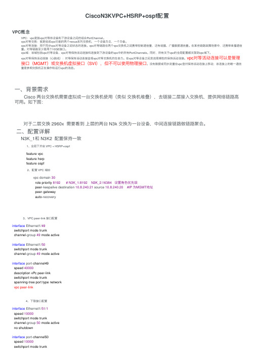
⼀、背景需求Cisco 两台交换机需要虚拟成⼀台交换机使⽤(类似 交换机堆叠),去链接⼆层接⼊交换机,提供⽹络链路⾼可⽤。
如下图: 对于⼆层交换 2960x 需要看到 上层的两台 N3k 交换为⼀台设备,中间连接链路做链路聚合。
⼆、配置详解 N3K_1和 N3K2 配置保持⼀致 1、全局下开启 VPC + HSRP+ospf 2、配置 VPC 域ID 3、VPC peer-link 接⼝配置 4、下联接⼝配置feature vpcfeature hsrpfeature ospfvpc domain 30role priority 8192 # N3K_1:8192 N3K_2:16384 设置⾓⾊优先级peer -keepalive destination 10.8.240.21 source 10.8.240.20 #IP 为MGMT 地址peer -gatewayauto -recoveryinterface Ethernet1/49switchport mode trunkchannel -group 49 mode activeinterface Ethernet1/50switchport mode trunkchannel -group 49 mode activeinterface port-channel49speed 40000description vPc peer -linkswitchport mode trunkspanning -tree port type networkvpc peer-linkinterface Ethernet1/51/1speed 10000switchport mode trunkchannel -group 50 mode activeno shutdowninterface port-channel50speed 10000switchport mode trunkvpc 50#两台N3K 的VPC ID 必须⼀致 2960X交换机配置 1:、接⼝配置(和普通链路聚合配置⼀样)interface TenGigabitEthernet1/0/1switchport mode trunkchannel-group 24 mode activeinterface TenGigabitEthernet1/0/2switchport mode trunkchannel-group 24 mode activeinterface Port-channel24switchport mode trunk三、hsrp+ospf 配置N3k_1:interface Vlan10no shutdownip address 192.168.0.2/24ip router ospf 10 area 0.0.0.20 #ospf 路由发布hsrp version 2hsrp 10preemptpriority 105ip 192.168.0.1track 1track 1interface Ethernet1/48 line-protocolN3k_2:interface Vlan10no shutdownip address 192.168.0.3/24ip router ospf 10 area 0.0.0.20hsrp version 2hsrp 10ip 192.168.0.1track 1track 1interface Ethernet1/48 line-protocol四、查看配置N3k-core-01# show vpcLegend:(*) - local vPC is down, forwarding via vPC peer-link vPC domain id : 30Peer status : peer adjacency formed okvPC keep-alive status : peer is alive Configuration consistency status : successPer-vlan consistency status : successType-2 consistency status : successvPC role : primary, operational secondary Number of vPCs configured : 6Peer Gateway : EnabledPeer gateway excluded VLANs : -Dual-active excluded VLANs : -Graceful Consistency Check : EnabledAuto-recovery status : Enabled (timeout = 240 seconds)vPC Peer-link status---------------------------------------------------------------------id Port Status Active vlans-- ---- ------ --------------------------------------------------1 Po49 up allvPC status----------------------------------------------------------------------------id Port Status Consistency Reason Active vlans------ ----------- ------ ----------- -------------------------- -----------50 Po50 up success success all51 Po51 up success success all52 Po52 up success success all53 Po53 up success success allN3k-core-01# show vpc statistics peer-linkport-channel49 is upHardware: Port-Channel, address: 0062.ecef.8e5c (bia 0062.ecef.8e5c)Description: vPc peer-linkMTU 9216 bytes, BW 80000000 Kbit, DLY 10 usecreliability 255/255, txload 1/255, rxload 1/255Encapsulation ARPAPort mode is trunkfull-duplex, 40 Gb/sInput flow-control is off, output flow-control is offSwitchport monitor is offEtherType is0x8100Members in this channel: Eth1/49, Eth1/50Last clearing of "show interface" counters never1interface resetsLoad-Interval #1: 30 seconds30 seconds input rate 13194296 bits/sec, 5755 packets/sec30 seconds output rate 1558864 bits/sec, 802 packets/secLoad-Interval #2: 5 minute (300 seconds)input rate 11.66 Mbps, 5.24 Kpps; output rate 1.49 Mbps, 625 ppsRX53092855268 unicast packets 943847523 multicast packets 37779519 broadcast packets 54074482310 input packets 12067581932262 bytes3615421391 jumbo packets 0 storm suppression packets0 runts 0 giants 0 CRC 0 no buffer0 input error 0short frame 0 overrun 0 underrun 0 ignored0 watchdog 0 bad etype drop 0 bad proto drop 0if down drop0 input with dribble 0 input discard0 Rx pauseTX27613649710 unicast packets 1107185465 multicast packets 48743817 broadcast packets 28769578992 output packets 4953197509995 bytes1283510513 jumbo packets0 output errors 0 collision 0 deferred 0 late collision0 lost carrier 0 no carrier 0 babble 0 output discard0 Tx pauseN3k-core-01# show hsrp briefP indicates configured to preempt.|Interface Grp Prio P State Active addr Standby addr Group addrVlan10 10105 P Active local 192.168.0.3192.168.0.1 (conf)Vlan11 11105 P Active local 1921.68.1.3192.168.1.1 (conf)。
Cisco 数据中心之 HSRP, vPC 以及 vPC Peer-Gateway 介绍
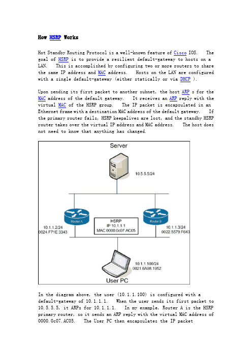
How HSRP WorksHot Standby Routing Protocol is a well-known feature of Cisco IOS. The goal of HSRP is to provide a resilient default-gateway to hosts on a LAN. This is accomplished by configuring two or more routers to share the same IP address and MAC address. Hosts on the LAN are configured with a single default-gateway (either statically or via DHCP ).Upon sending its first packet to another subnet, the host ARP s for the MAC address of the default gateway. It receives an ARP reply with the virtual MAC of the HSRP group. The IP packet is encapsulated in an Ethernet frame with a destination MAC address of the default gateway. If the primary router fails, HSRP keepalives are lost, and the standby HSRP router takes over the virtual IP address and MAC address. The host does not need to know that anything has changed.In the diagram above, the user (10.1.1.100) is configured with a default-gateway of 10.1.1.1. When the user sends its first packet to 10.5.5.5, it ARPs for 10.1.1.1. In my example, Router A is the HSRP primary router, so it sends an ARP reply with the virtual MAC address of 0000.0c07.AC05. The User PC then encapsulates the IP packet(destination IP=10.5.5.5) in an Ethernet frame with a destination MAC address of 0000.0c07.AC05. Router A accepts the frame and routes the packet.The above paragraphs tell the story of packets coming from theHSRP-enabled LAN. But what happens to reply packets coming from10.5.5.5 to 10.1.1.100? The answer is simple, and intuitive if you follow step-by-step. First, the Server creates an IP packet with a destination of 10.1.1.100. It encapsulates it in an Ethernet frame and forwards it to its default gateway (for this example, let’s say it is Router A). Router A strips the Ethernet framing and determines the next hop is on the local subnet 10.1.1.0/24. It encapsulates the packet in an Ethernet frame with a MAC address of 0021.6a98.1952. The source MAC address is the physical MAC address of Router A(0024.F71E.3343). Router A does not use the virtual MAC address for packets it routes onto the local subnet.So What is vPC ?Now that we’ve covered HSRP, let’s talk about Virtual P ort Channeling ( vPC ). vPC allows two NX-OS devices to share aport-channel. Attached devices believe that they are connected to a single device via an etherchannel bundle. This is great because it eliminates spanning-tree blocking along parallel paths.To allow this to work, the paired NX-OS devices use two vpc-specific communication channels. The first is a vpc peer-keepalivemessage. This heartbeat lets one switch detect when the other has gone off-line, to prevent traffic from being dropped during a failure. These are lightweight hello packets.The second communication channel is the vpc peer-link . This is a high-speed connection between the two NX-OS switches that is used to stitch together the two sides of the port-channel. If a frame arrives on switch A, but is destined for a host on switch B, it is forwarded across the peer-link for delivery. All things being equal, it is undesirable to forward frames across a vpc peer-link. It is much better for the frame to be sent to the correct switch in the first place. Of course, there’s no way for the attached device to know which path is more appropriate.In the above example, the User PC is sending an Ethernet frame to the Server. It creates a frame with a destination MAC address of0033.9328.12A1 and sends it to the L2 Switch. The L2 switch has an entry in his forwarding table indicating that the destination MAC is accessible via the Port-Channel 100 interface. It uses its etherchannel load balancing hash algorithm to determine which physical interface to forward the frame onto. It is equally likely that it will choose the link to Nexus B, even though the more efficient path is to Nexus A (someday TRILL will help us, but for now there is no solution). If the frame is sent to Nexus B, it will forward the frame over the vPC peer-link to Nexus A.Cisco’s current recommendation is to build the vPC peer-link with multiple dedicated 10GE connections for performance reasons. Cisco also recommends that all devices in a vPC-enabled VLAN be connected to both Nexus switches. In the diagram above, the Server is considered tobe a vpc orphan port. This is undesirable, since it requires usage of the vpc peer-link. It also has implications with multicast traffic forwarding.vPC and HSRP TogetherNow we’ve arrived at the point where we can pull all this information together. In the following diagram, the User PC has been moved to a new VLAN. The user is again trying to communicate with the server.The User PC ARPs for his default gateway. Nexus A (the HSRP primary) replies with the virtual MAC address of 000.0C07.AC05. The user createsan Ethernet frame with a destination address of the virtual MAC. It then forwards the frame to the L2 Switch. The L2 Switch uses its etherchannel load balancing algorithm to determine the physical link to use. The difference is now that it doesn’t matter which link it uses. The NX-OS switch on the other end will accept and route the packet. In effect, both Nexus switches are HSRP active at the same time. This is eliminates the need to forward Ethernet frames across the vPC peer-link for packets that are destined for other subnets.What Does “vpc peer-gateway” Do?If we left everything alone, the story would be complete. Unfortunately, storage vendors thought it would be a good idea to optimize their handling of Ethernet frames. Some NetApp and EMC equipment ignores the ARP reply given by the HSRP primary and instead forwards Ethernet frames to whichever MAC address it receives frames from. This is nonstandard behavior.Using the diagram above, let‘s assume say that the User PC is now a EMC Celera storage device. The Server sends its packets (IP destination 10.1.1.100) to Nexus B, which routes them to the Ethernet LAN. All IP packets with source IP 10.5.5.5 will be encapsulated in Ethernet frames with a source MAC address of 0022.5579.F643. The EMC Celera will cache the source MAC address of these frames, and when it has IP packets to send to 10.5.5.5, it will encapsulate them in Ethernet frames with a destination MAC of 0022.5579.F643. It is choosing to ignore its default gateway for these outbound packets.I suppose the theory behind this feature was to eliminate the extra hop within the LAN. When HSRP is enabled, it is necessary to disable ICMP redirects. This means that the routers will not inform hosts on the LAN that a better default-gateway is available for a particular destination IP address. This storage feature saves a LAN hop.Unfortunately, this optimization does not work well with vPC. vPC relies on virtual MAC address sharing to reduce utilization across the vPC peer-link. If hosts insist on addressing their frames to a specific router, suboptimal packet forwarding can occur. According to Cisco , “Packets reaching a vPC device for the non-local router MAC address are sent across the peer-link and could be dropped by the built in vPC loop avoidance mechanism if the final destination is behind another vPC.” At the application level we saw very poor performance due to these dropped packets. Enough of the packets got through to allow accessto the storage device, but file load times were measured in the tens of seconds, rather than milliseconds.The “vpc peer-gateway” allows HSRP routers to accept frames destined for their vPC peers. This feature extends the virtual MAC address functionality to the paired router’s MAC address. By enabling this feature, NX-OS effectively disables the storage vendors’ optimization.ConclusionIf you are running vPC and HSRP, and you have EMC or NetApp storage equipment, you probably need to add the “peer-gatew ay” command under your vpc configuration. The only caveat to peer-gateway is the following (from NX-OS 5.0 – Configuring vPC ):Packets arriving at the peer-gateway vPC device will have their TTL decremented, so packets carrying TTL = 1 may be dropped in transit due to TTL expire. This needs to be taken into account when the peer-gateway feature is enabled and particular network protocols sourcing packets with TTL = 1 operate on a vPC VLAN.I have yet to face this issue, so my recommendation is to add this to your vpc configuration as a default.。
CiscoVPC学习笔记
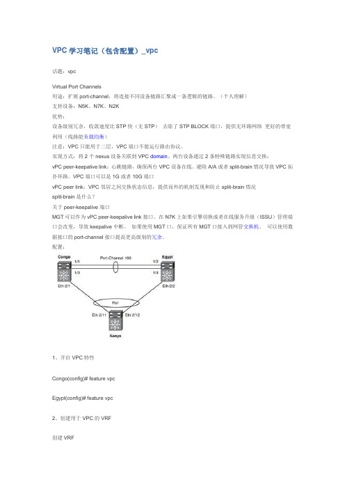
VPC学习笔记(包含配置)_vpc话题:vpcVirtual Port Channels用途:扩展port-channel,将连接不同设备链路汇聚成一条逻辑的链路。
(个人理解)支持设备:N5K、N7K、N2K优势:设备级别冗余,收敛速度比STP快(无STP)去除了STP BLOCK端口,提供无环路网络更好的带宽利用(线路能负载均衡)注意:VPC只能用于二层,VPC端口不能运行路由协议。
实现方式:将2个nexus设备关联到VPC domain。
两台设备通过2条特殊链路实现信息交换:vPC peer-keepalive link:心跳链路,确保两台VPC设备在线。
避险A/A或者split-brain情况导致VPC拓扑环路。
VPC端口可以是1G或者10G端口vPC peer link:VPC邻居之间交换状态信息,提供而外的机制发现和防止split-brain情况split-brain是什么?关于peer-keepalive端口MGT可以作为vPC peer-keepalive link接口。
在N7K上如果引擎切换或者在线服务升级(ISSU)管理端口会改变,导致keepalive中断。
如果使用MGT口,保证所有MGT口接入到网管交换机。
可以使用数据接口的port-channel接口提高更高级别的冗余。
配置:1、开启VPC特性Congo(config)# feature vpcEgypt(config)# feature vpc2、创建用于VPC的VRF创建VRFCongo(config-if)# vrf context vpc-keepaliveEgypt(config)# vrf context vpc-keepalive3、创建VPC keeplive链路Congo(config)# int ethernet 2/47Congo(config-if)#no switchportCongo(config-if)# vrf member vpc-keepaliveCongo(config-if)# ip address 1.1.1.1 255.255.255.252 Egypt(config)# interface ethernet 2/48Egypt(config-if)# no switchportEgypt(config-if)# vrf member vpc-keepaliveEgypt(config-if)# ip address 1.1.1.2 255.255.255.252测试连通性:Congo# ping 1.1.1.2 vrf vpc-keepalive 查看:Congo# sho vpcLegend:(*) - local vPC is down, forwarding via vPC peer-link vPC domain id : 1Peer status : peer link not configuredvPC keep-alive status : peer is aliveConfiguration consistency status: failedConfiguration consistency reason: vPC peer-link does not existsvPC role : none establishedNumber of vPCs configured : 0Peer Gateway : DisabledDual-active excluded VLANs : -可以看到keepalive已经OK,但vpc peer没有起来4、建立VPC-domainCongo(config)# vpc domain 1Congo(config-vpc-domain)# peer-keepalive destination 1.1.1.2 source1.1.1.1 vrf vpc-keepalive Egypt(config)# vpc domain 1Egypt(config-vpc-domain)# peer-keepalive destination 1.1.1.1 source1.1.1.2 vrf vpc-keepalive 5、配置VPC peer链路(NEXUS交换机互联)必须使用10G端口,并且指定速率。
VSS,IRF,VPC,VDC总结
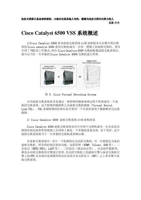
这份文档我只是总结性质的,大部分还是其他人写的,感谢为这份文档付出努力的人北京-小小Cisco Catalyst 6500 VSS系统概述1)Cisco Catalyst 6500系列虚拟交换系统1440初始版本可以整合两台物理的Cisco catalyst 6500系列交换机成为一台单一逻辑上的虚拟交换机。
图5介绍了VSS的工作模式,两台Cisco Catalyst 6509交换机配置虚拟交换系统后,就可以当作一台单独的Cisco Catalyst 6509交换机进行管理。
图 5. Cisco Virtual Switching System启用虚拟交换系统技术是通过一条特殊的链路来绑定两个机架成为一个虚拟的交换系统,这个特殊的链路称之为虚拟交换机链路(Virtual Switch Link,VSL)。
VSL承载特殊的控制信息并使用一个头部封装每个数据帧穿过这条链路。
2) Cisco Catalyst 6500 虚拟交换系统1440架构体系Cisco Catalyst 6500虚拟交换系统允许合并两个交换机成为一台无论是从网络控制层面和管理视图上在网络上都是一个单独的设备实体。
对于邻居,这个虚拟交换系统相当于一台单独的交换机或者路由器。
在虚拟交换系统中,其中一个机箱指定为活跃交换机,另一台被指定为备份虚拟交换机。
所有的控制层面的功能,包括管理(SNMP,Telnet,SSH等),二层协议(BPDU,PDUs,LACP等),三层协议(路由协议等),以及软件数据等,都是由活跃交换机的引擎进行管理。
在活跃交换机上的超级引擎与备份交换机引擎上的PFC负责响应处理硬件转发信息到分布式转发卡(DFC)之上贯穿整个虚拟交换系统。
图6. Components of Cisco Virtual Switching System从数据层面和流量转发图上来看,在虚拟交换系统1440中的所有交换机都参与流量转发。
在活跃虚拟交换机超级引擎上的PFC执行为所有进入活跃虚拟交换机的流量转发查找,位于备份状态的交换机引擎上的PFC执行为所有进入备份状态交换机流量转发查找。
HSRP详解

HSRP(2012-08-24 20:08:22)转载▼分类:Cisco路由入门标签:上关hsrp负载平衡路由器r1优先级r3简介HSRP(Hot Standby Router Protocol 热备份路由器协议)是Cisco的专有协议。
HSRP把多台路由器组成一个“热备份组”,形成一个虚拟路由器。
这个组内只有一个路由器是Active(活动)的,并由它来转发数据包,如果活动路由器发生了故障,备份路由器将成为活动路由器。
从网络内的主机来看,网关并没有改变。
HSRP的工作过程:HSRP路由器利用Hello包来互相监听各自的存在。
当路由器长时间没有接收到Hello包时,就认为活动路由器故障,备份路由器就会成为活动路由器。
HSRP协议利用优先级决定哪个路由器成为活动路由器。
如果一个路由器的优先级比其它路由器的优先级高,则该路由器成为活动路由器。
路由器的默认优先级是100。
在一个组中,最多有一个活动路由器和一个备份路由器。
HSRP路由器发送的组播(224.0.0.2)消息有以下三种:Hello:通知其它路由器发送者的HSRP优先级和状态信息,HSRP路由器默认每3秒发送一个Hello 消息。
Coup:当一个备用路由器变为一个活动路由器时发送一个Coup消息。
Resign:当活动路由器要当机或者当有优先级更高的路由器发送Hello消息时,主动发送一个Resign 消息。
HSRP的报文格式:①版本:指示HSRP的版本信息。
②操作码:用来描述数据包中报文的类型,可能的值为0、1和2,分别表示是Hello、Coup和Resign 消息。
③状态:描述发出该报文的路由器的当前状态。
有0、1、2、4、8、16六种状态,分别表示为Initial、Learn、Listen、Speak、Standby和Active状态。
④呼叫时间(Hellotime):只在呼叫报文中有意义,表示路由器定时发送呼叫报文的间隔时间,以秒为单位。
Cisco HSRP 路由器的配置
Cisco HSRP 路由器的配置1、介绍本文档将详细说明如何配置Cisco HSRP(Hot Standby Router Protocol)路由器。
HSRP是一种用于提供冗余路由的协议,通过同时配置多个路由器来实现高可靠性和冗余性。
在本文档中,将介绍HSRP的概念、配置过程以及一些常见问题的解决方法。
2、HSRP概念及工作原理⑴ HSRP概念HSRP是一种用于提供冗余路由的协议,通过将多个路由器配置为一个虚拟路由器来实现冗余性。
在一个HSRP组中,有一个主路由器和一个或多个备用路由器。
主路由器负责转发数据流量,而备用路由器在主路由器失效时接管主路由器的功能。
⑵ HSRP工作原理每个HSRP组都有一个主要的虚拟IP地质,该地质与组中的主路由器相对应。
当主路由器失效时,备用路由器中的其中一个将成为新的主路由器,接管原先主路由器的功能,并使用相同的虚拟IP 地质。
主路由器和备用路由器通过互相发送心跳包来检测彼此的状态。
3、配置前的准备工作在开始配置HSRP之前,确保满足以下条件:⑴路由器上已运行适当的IOS版本,支持HSRP功能。
⑵彼此连接的路由器中至少有两台路由器。
⑶路由器之间配置了适当的接口,并具有可达性。
4、HSRP配置步骤以下是配置Cisco HSRP路由器的步骤:⑴创建HSRP组在每台路由器上创建HSRP组,使用相同的组号,并指定虚拟IP地质。
⑵配置接口在每台路由器的接口上配置HSRP,并将其指定为HSRP组的一部分。
⑶配置优先级为了指定主路由器,您可以配置每个路由器的HSRP优先级。
优先级越高,该路由器成为主路由器的可能性越大。
⑷配置其他参数根据需求,您还可以配置其他一些参数,如预共享密钥、追踪对象等。
5、常见问题及解决方法⑴ HSRP状态不稳定如果HSRP状态频繁切换或不稳定,可能是由于网络问题或路由器之间的通信问题引起的。
检查网络连接并确保良好的通信。
⑵主路由器失效后备用路由器无法接管如果主路由器失效后备用路由器无法接管其功能,可能是由于HSRP组配置错误或接口问题。
vPC技术介绍
vPC peer-link --- vPC peer 之间的链路,用于状态 和信息的同步,必须为10GE链路。
vPC peer-keepalive link --- vPC peer 之间的心跳线 ,用于监控 peer device 。
© 2007 Cisco Systems, Inc. All rights reserved.
Cisco Confidential
3
Agenda
vPC基本原理
vPC概述 vPC组件与原理 vPC基本业务流
vPC网络设计和最佳实践
Attaching to a vPC domain Layer 3 and vPC STP 建议 HSRP with vPC ISSU
Cisco Confidential
5
vPC Domain
vPC peer 双方均需要定义 vPC Domain , 建议两边的 Domain ID 一致。
在Domain mode 下定义 vPC 的全局参数 —角色优先级(低值优先)、keepalive 等。
vPC peer 设备使用Domain ID 自动产生一 个唯一的 vPC System-MAC 。
vPC技术原理介绍
© 2007 Cisco Systems, Inc. All rights reserved. Cisco Confidential
1
Agenda
vPC基本原理
vPC概述 vPC组件与原理 vPC基本业务流
vPC网络设计和最佳实践
Attaching to a vPC domain Layer 3 and vPC STP 建议 HSRP with vPC ISSU
HSRP配置总结
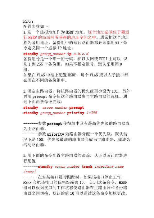
HSRP:配置步骤如下:1.选一个虚拟地址作为HSRP地址。
这个地址必须位于要运行HSRP的局域网所获得的地址空间之中。
通常把这个地址称为备用地址。
备份组中的每台路由器都必须都用如下命令定义同一个虚拟IP地址。
standby group_number ip a.b.c.d备份组号是一个唯一的号码,在以太网或FDDI上可以识别1到255个备份组,如果不指定组号,默认采用第0组。
如果在VLAN中继上配置HSRP,每个VLAN或以太子接口都必须在不同的备份组中。
2.确定主路由器,将该路由器的优先级至少设为101。
另外再用preempt命令使这台路由器参与主路由器的选择。
通过下面两条命令完成:standby group_number preemptstandby group_number priority 1-255-------参数preempt使得组中具有最高优先级的路由器成为主路由器。
-------参数priority为路由器分配一个优先级,默认情况下是100,优先级最高的路由器会成为主路由器,或成为活动路由器。
3.用下面的命令配置主路由器的跟踪,认证以及计时器进行配置-------standby group_number track interface_name [cost]-------在对某接口进行跟踪时,如果该接口停止工作,HSRP会把该接口的优先级减去10。
运用这条命令,HSRP 组可以根据接口的工作状态使路由器在主路由器和备份路由器之间切换。
默认的值10可以通过这条命令加以更改。
-------standby group_number authentication character_string-------这条命令可以创建认证信息以进行HSRP组操作,这样可是确保只有授权了的路由器才能进入HSRP组中。
这里的“character_string”字符串必须和HSRP组中所有的路由器项匹配。
思科交换机HSRP配置
配置路由器 B: Router2(config-if-Ethernet0)# standby 1 ip 202.38.160.111 Router2(config-if-Ethernet0)# standby 1 preempt Router2(config-if-Ethernet0)# standby 1 authentication Router Router2(config-if-Ethernet0)# standby 1 timers 5 15
(3)配置说明 正常情况下,路由器 A 执行网关工作,当路由器 A 的接口 serial0 不可用时,路 由器 A 的优先级降低 30,低于路由器 B 优先级,路由器 B 将抢占成为活动路由 器执行网关工作。 当路由器 A 的接口 serial0 恢复工作后,路由器 A 能够继续成为活动路由器执行 网关工作。
思科交换机 HSRP 配置
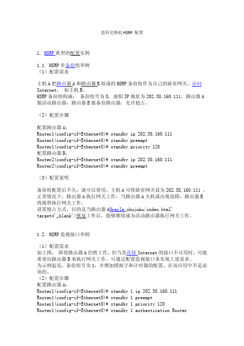
1. HSRP 典型的配置实例
1.1. HSRP 单备份组举例 (1)配置需求
主机 A 把路由器 A 和路由器 B 组成的 HSRP 备份组作为自己的缺省网关,访问 Internet, 如主机 B。 HSRP 备份组构成: 备份组号为 0, 虚拟 IP 地址为 202.38.160.111,路由器 A 做活动路由器,路由器 B 做备份路由器, 允许抢占。
1.2. HSRP 监视接口举例
(1)配置需求 如上图, 即使路由器 A 仍然工作,但当其连接 Internet 的接口不可用时,可能 希望由路由器 B 来执行网关工作。可通过配置监视接口来实现上述需求。 为示例起见,备份组号为 1,并增加授权字和计时器的配置,在该应用中不是必 须的。 (2)配置步骤 配置路由器 A: Router1(config-if-Ethernet0)# standby 1 ip 202.38.160.111 Router1(config-if-Ethernet0)# standby 1 preempt Router1(config-if-Ethernet0)# standby 1 priority 120 Router1(config-if-Ethernet0)# standby 1 authentication Router
vPC技术详解
17
議程
▪ VPC基本原理
- VPC 概述 - VPC 組件和原理 - VPC 基本業務流
▪ VPC 的交互操作
- VPC 和VDC 的交互操作 - VPC和ISSU的交互操作 - VPC和 STP 的交互操作 - VPC和HSRP 的交互操作
▪ VPC故障恢復
▪ 最佳實踐
▪ Q&A © 2009 Cisco Systems, Inc. All rights reserved.
Cisco Confidential
18
Nexus 7000 VDC 簡介
虛擬化
Virtual Device Context ✓ 一個物理設備上虛擬多個
邏輯裝置 ✓ 靈活的硬體資源配置 ✓ 軟體功能以及故障隔離 ✓ 有效提高資源利用率 ✓ 安全獨立的管理模式
VDC 1 VDC 2 VDC 3 VDC 4
▪ VPC故障恢復
▪ 最佳實踐
▪ Q&A © 2009 Cisco Systems, Inc. All rights reserved.
Cisco Confidential
15
單播——從Mac_A 到 Mac_B
Packet Send
PackPeat cFkloeotding Flooding
ECMP
Cisco Confidential
4
vPC 術語和組件
vPC Domain vPC peer-keepalive
link
vPC
vPC peer-link CFS protocol
non-vPC device
vPC peer mmeevvPPmmCCbbeerr
ppoorrtt
HSRP(热备份路由器协议)的详细介绍-电脑资料

HSRP(热备份路由器协议)的详细介绍-电脑资料HSRP:热备份路由器协议(HSRP:Hot Standby Router Protocol),是cisco平台一种特有的技术,是cisco的私有协议,。
Part I: FundamentalHSRP(Hot Standby Router Protocol):Cisco私有的第3层协议。
HSRP为IP网络提供网络冗余,确保用户流量能立即并透明地恢复网络边界设备或接入电路中的第一跳故障。
在LAN中,多个router组成一个HSRP组,其中一个router代表这个HSRP转发这个LAN中的数据流,其它所有router只发送HSRP hello来维持这种HSRP组关系。
一个HSRP组共享一个IP和一个MAC地址。
每个router可以加入多个组。
一个HSRP组由一台active router,一台standby router及other routers。
1>active router转发指向VIP的数据流,并发送HSRP hello包给所有其它HSRP组成员。
(最终处于active state)2>standby router不转发指向VIP的数据流,发送HSRP hello 包给所有其它HSRP组成员,并监控active router的状态。
(最终处于standby state)3>other routers不转发指向VIP的数据流,只监控HSRP hello 包,不发送。
它们执行普通router的工作,只转发目标为他们自己的分组,不转发目标为VIP的地址。
(最终处于listen state)Part II: HSRP Operation当standby router在一定时间内没有收到active router的hello 包时,它就认为active router出现故障了,并取代它的active router 的角色。
因为host设备使用VIP及VMAC来标识它们的网关设备,所有它们不会发现这种变更,也不会感觉到服务的中断。
Cisco基础(三):HSRP配置、三层交换配置HSRP、STP的配置、三层交换配置STP
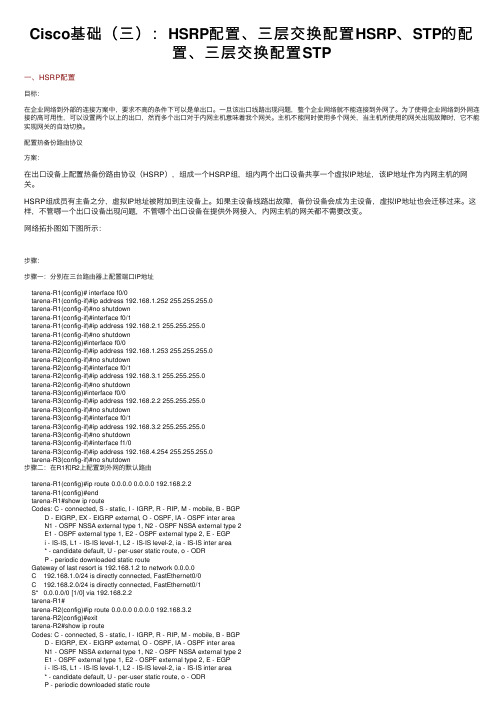
Cisco基础(三):HSRP配置、三层交换配置HSRP、STP的配置、三层交换配置STP⼀、HSRP配置⽬标:在企业⽹络到外部的连接⽅案中,要求不⾼的条件下可以是单出⼝。
⼀旦该出⼝线路出现问题,整个企业⽹络就不能连接到外⽹了。
为了使得企业⽹络到外⽹连接的⾼可⽤性,可以设置两个以上的出⼝,然⽽多个出⼝对于内⽹主机意味着我个⽹关。
主机不能同时使⽤多个⽹关,当主机所使⽤的⽹关出现故障时,它不能实现⽹关的⾃动切换。
配置热备份路由协议⽅案:在出⼝设备上配置热备份路由协议(HSRP),组成⼀个HSRP组,组内两个出⼝设备共享⼀个虚拟IP地址,该IP地址作为内⽹主机的⽹关。
HSRP组成员有主备之分,虚拟IP地址被附加到主设备上。
如果主设备线路出故障,备份设备会成为主设备,虚拟IP地址也会迁移过来。
这样,不管哪⼀个出⼝设备出现问题,不管哪个出⼝设备在提供外⽹接⼊,内⽹主机的⽹关都不需要改变。
⽹络拓扑图如下图所⽰:步骤:步骤⼀:分别在三台路由器上配置端⼝IP地址tarena-R1(config)# interface f0/0tarena-R1(config-if)#ip address 192.168.1.252 255.255.255.0tarena-R1(config-if)#no shutdowntarena-R1(config-if)#interface f0/1tarena-R1(config-if)#ip address 192.168.2.1 255.255.255.0tarena-R1(config-if)#no shutdowntarena-R2(config)#interface f0/0tarena-R2(config-if)#ip address 192.168.1.253 255.255.255.0tarena-R2(config-if)#no shutdowntarena-R2(config-if)#interface f0/1tarena-R2(config-if)#ip address 192.168.3.1 255.255.255.0tarena-R2(config-if)#no shutdowntarena-R3(config)#interface f0/0tarena-R3(config-if)#ip address 192.168.2.2 255.255.255.0tarena-R3(config-if)#no shutdowntarena-R3(config-if)#interface f0/1tarena-R3(config-if)#ip address 192.168.3.2 255.255.255.0tarena-R3(config-if)#no shutdowntarena-R3(config-if)#interface f1/0tarena-R3(config-if)#ip address 192.168.4.254 255.255.255.0tarena-R3(config-if)#no shutdown步骤⼆:在R1和R2上配置到外⽹的默认路由tarena-R1(config)#ip route 0.0.0.0 0.0.0.0 192.168.2.2tarena-R1(config)#endtarena-R1#show ip routeCodes: C - connected, S - static, I - IGRP, R - RIP, M - mobile, B - BGPD - EIGRP, EX - EIGRP external, O - OSPF, IA - OSPF inter areaN1 - OSPF NSSA external type 1, N2 - OSPF NSSA external type 2E1 - OSPF external type 1, E2 - OSPF external type 2, E - EGPi - IS-IS, L1 - IS-IS level-1, L2 - IS-IS level-2, ia - IS-IS inter area* - candidate default, U - per-user static route, o - ODRP - periodic downloaded static routeGateway of last resort is 192.168.1.2 to network 0.0.0.0C 192.168.1.0/24 is directly connected, FastEthernet0/0C 192.168.2.0/24 is directly connected, FastEthernet0/1S* 0.0.0.0/0 [1/0] via 192.168.2.2tarena-R1#tarena-R2(config)#ip route 0.0.0.0 0.0.0.0 192.168.3.2tarena-R2(config)#exittarena-R2#show ip routeCodes: C - connected, S - static, I - IGRP, R - RIP, M - mobile, B - BGPD - EIGRP, EX - EIGRP external, O - OSPF, IA - OSPF inter areaN1 - OSPF NSSA external type 1, N2 - OSPF NSSA external type 2E1 - OSPF external type 1, E2 - OSPF external type 2, E - EGPi - IS-IS, L1 - IS-IS level-1, L2 - IS-IS level-2, ia - IS-IS inter area* - candidate default, U - per-user static route, o - ODRP - periodic downloaded static routeGateway of last resort is 192.168.2.2 to network 0.0.0.0C 192.168.1.0/24 is directly connected, FastEthernet0/0C 192.168.3.0/24 is directly connected, FastEthernet0/1S* 0.0.0.0/0 [1/0] via 192.168.3.2步骤三:在R3上配置到企业内⽹的静态路由tarena-R3(config)#ip route 192.168.1.0 255.255.255.0 192.168.2.1tarena-R3(config)#ip route 192.168.1.0 255.255.255.0 192.168.3.1tarena-R3(config)#endtarena-R3#show ip routeCodes: C - connected, S - static, I - IGRP, R - RIP, M - mobile, B - BGPD - EIGRP, EX - EIGRP external, O - OSPF, IA - OSPF inter areaN1 - OSPF NSSA external type 1, N2 - OSPF NSSA external type 2E1 - OSPF external type 1, E2 - OSPF external type 2, E - EGPi - IS-IS, L1 - IS-IS level-1, L2 - IS-IS level-2, ia - IS-IS inter area* - candidate default, U - per-user static route, o - ODRP - periodic downloaded static routeGateway of last resort is not setS 192.168.1.0/24 [1/0] via 192.168.2.1[1/0] via 192.168.3.1C 192.168.2.0/24 is directly connected, FastEthernet0/0C 192.168.3.0/24 is directly connected, FastEthernet0/1C 192.168.4.0/24 is directly connected, FastEthernet1/0tarena-R3#步骤四:在R1上配置HSRP,指定其优先级为200HSRP的默认优先级为100,路由器启动后,根据优先级决定谁可以成为活跃路由器,优先级⾼的将胜出。
Cisco Nexus 数据中心交换机配置介绍
Journey2011.11一、 Nexus 5000 基础配置Ø 为N5K交换机配管理接口及 管理接口及IP地址。
Ø 激活Layer 3 License Ø 软件升级1.1 初始化配置系统加电自检通过后,进入系统初始化界面 进入系统初始化界面,如下操作: ---- System Admin Account Setup ---Do you want to enforce secure password standard (yes/no): no Enter the password for "admin": P@ssw0rd Confirm the password for "admin": P@ssw0rd Would you like to enter the basic configuration dialog (yes/no): no 输入管理账号和密码进入配置模式配置管理 IP:switch login: admin Password: P@ssw0rd switch # configure terminal switch #(config)# interface mgmt0 (config)# switch (config-if)# ip address 192.168.2.82 255.255.255.0 if)# switch (config-if)#no shut down no switch (config-if)#exit switch (config)# copy run start1.2 用购买的 License 激活 Layer 3 License:首先需要查看 hostid, ,用来绑定 License,命令如下 switch# show license host-id idLicense hostid: VDH=FOX17 731KTV5 “FOX1731KTV5”即为该设备的 hostid,复制出来备用。
- 1、下载文档前请自行甄别文档内容的完整性,平台不提供额外的编辑、内容补充、找答案等附加服务。
- 2、"仅部分预览"的文档,不可在线预览部分如存在完整性等问题,可反馈申请退款(可完整预览的文档不适用该条件!)。
- 3、如文档侵犯您的权益,请联系客服反馈,我们会尽快为您处理(人工客服工作时间:9:00-18:30)。
How HSRP WorksHot Standby Routing Protocol is a well-known feature of Cisco IOS. The goal of HSRP is to provide a resilient default-gateway to hosts on a LAN. This is accomplished by configuring two or more routers to share the same IP address and MAC address. Hosts on the LAN are configured with a single default-gateway (either statically or via DHCP ).Upon sending its first packet to another subnet, the host ARP s for the MAC address of the default gateway. It receives an ARP reply with the virtual MAC of the HSRP group. The IP packet is encapsulated in an Ethernet frame with a destination MAC address of the default gateway. If the primary router fails, HSRP keepalives are lost, and the standby HSRP router takes over the virtual IP address and MAC address. The host does not need to know that anything has changed.In the diagram above, the user (10.1.1.100) is configured with a default-gateway of 10.1.1.1. When the user sends its first packet to 10.5.5.5, it ARPs for 10.1.1.1. In my example, Router A is the HSRP primary router, so it sends an ARP reply with the virtual MAC address of 0000.0c07.AC05. The User PC then encapsulates the IP packet(destination IP=10.5.5.5) in an Ethernet frame with a destination MAC address of 0000.0c07.AC05. Router A accepts the frame and routes the packet.The above paragraphs tell the story of packets coming from theHSRP-enabled LAN. But what happens to reply packets coming from10.5.5.5 to 10.1.1.100? The answer is simple, and intuitive if you follow step-by-step. First, the Server creates an IP packet with a destination of 10.1.1.100. It encapsulates it in an Ethernet frame and forwards it to its default gateway (for this example, let’s say it is Router A). Router A strips the Ethernet framing and determines the next hop is on the local subnet 10.1.1.0/24. It encapsulates the packet in an Ethernet frame with a MAC address of 0021.6a98.1952. The source MAC address is the physical MAC address of Router A(0024.F71E.3343). Router A does not use the virtual MAC address for packets it routes onto the local subnet.So What is vPC ?Now that we’ve covered HSRP, let’s talk about Virtual P ort Channeling ( vPC ). vPC allows two NX-OS devices to share aport-channel. Attached devices believe that they are connected to a single device via an etherchannel bundle. This is great because it eliminates spanning-tree blocking along parallel paths.To allow this to work, the paired NX-OS devices use two vpc-specific communication channels. The first is a vpc peer-keepalivemessage. This heartbeat lets one switch detect when the other has gone off-line, to prevent traffic from being dropped during a failure. These are lightweight hello packets.The second communication channel is the vpc peer-link . This is a high-speed connection between the two NX-OS switches that is used to stitch together the two sides of the port-channel. If a frame arrives on switch A, but is destined for a host on switch B, it is forwarded across the peer-link for delivery. All things being equal, it is undesirable to forward frames across a vpc peer-link. It is much better for the frame to be sent to the correct switch in the first place. Of course, there’s no way for the attached device to know which path is more appropriate.In the above example, the User PC is sending an Ethernet frame to the Server. It creates a frame with a destination MAC address of0033.9328.12A1 and sends it to the L2 Switch. The L2 switch has an entry in his forwarding table indicating that the destination MAC is accessible via the Port-Channel 100 interface. It uses its etherchannel load balancing hash algorithm to determine which physical interface to forward the frame onto. It is equally likely that it will choose the link to Nexus B, even though the more efficient path is to Nexus A (someday TRILL will help us, but for now there is no solution). If the frame is sent to Nexus B, it will forward the frame over the vPC peer-link to Nexus A.Cisco’s current recommendation is to build the vPC peer-link with multiple dedicated 10GE connections for performance reasons. Cisco also recommends that all devices in a vPC-enabled VLAN be connected to both Nexus switches. In the diagram above, the Server is considered tobe a vpc orphan port. This is undesirable, since it requires usage of the vpc peer-link. It also has implications with multicast traffic forwarding.vPC and HSRP TogetherNow we’ve arrived at the point where we can pull all this information together. In the following diagram, the User PC has been moved to a new VLAN. The user is again trying to communicate with the server.The User PC ARPs for his default gateway. Nexus A (the HSRP primary) replies with the virtual MAC address of 000.0C07.AC05. The user createsan Ethernet frame with a destination address of the virtual MAC. It then forwards the frame to the L2 Switch. The L2 Switch uses its etherchannel load balancing algorithm to determine the physical link to use. The difference is now that it doesn’t matter which link it uses. The NX-OS switch on the other end will accept and route the packet. In effect, both Nexus switches are HSRP active at the same time. This is eliminates the need to forward Ethernet frames across the vPC peer-link for packets that are destined for other subnets.What Does “vpc peer-gateway” Do?If we left everything alone, the story would be complete. Unfortunately, storage vendors thought it would be a good idea to optimize their handling of Ethernet frames. Some NetApp and EMC equipment ignores the ARP reply given by the HSRP primary and instead forwards Ethernet frames to whichever MAC address it receives frames from. This is nonstandard behavior.Using the diagram above, let‘s assume say that the User PC is now a EMC Celera storage device. The Server sends its packets (IP destination 10.1.1.100) to Nexus B, which routes them to the Ethernet LAN. All IP packets with source IP 10.5.5.5 will be encapsulated in Ethernet frames with a source MAC address of 0022.5579.F643. The EMC Celera will cache the source MAC address of these frames, and when it has IP packets to send to 10.5.5.5, it will encapsulate them in Ethernet frames with a destination MAC of 0022.5579.F643. It is choosing to ignore its default gateway for these outbound packets.I suppose the theory behind this feature was to eliminate the extra hop within the LAN. When HSRP is enabled, it is necessary to disable ICMP redirects. This means that the routers will not inform hosts on the LAN that a better default-gateway is available for a particular destination IP address. This storage feature saves a LAN hop.Unfortunately, this optimization does not work well with vPC. vPC relies on virtual MAC address sharing to reduce utilization across the vPC peer-link. If hosts insist on addressing their frames to a specific router, suboptimal packet forwarding can occur. According to Cisco , “Packets reaching a vPC device for the non-local router MAC address are sent across the peer-link and could be dropped by the built in vPC loop avoidance mechanism if the final destination is behind another vPC.” At the application level we saw very poor performance due to these dropped packets. Enough of the packets got through to allow accessto the storage device, but file load times were measured in the tens of seconds, rather than milliseconds.The “vpc peer-gateway” allows HSRP routers to accept frames destined for their vPC peers. This feature extends the virtual MAC address functionality to the paired router’s MAC address. By enabling this feature, NX-OS effectively disables the storage vendors’ optimization.ConclusionIf you are running vPC and HSRP, and you have EMC or NetApp storage equipment, you probably need to add the “peer-gatew ay” command under your vpc configuration. The only caveat to peer-gateway is the following (from NX-OS 5.0 – Configuring vPC ):Packets arriving at the peer-gateway vPC device will have their TTL decremented, so packets carrying TTL = 1 may be dropped in transit due to TTL expire. This needs to be taken into account when the peer-gateway feature is enabled and particular network protocols sourcing packets with TTL = 1 operate on a vPC VLAN.I have yet to face this issue, so my recommendation is to add this to your vpc configuration as a default.。