SJR-BTM870-C蓝牙模块规格书
基尔斯特 2157B NC 连接模块手册说明书
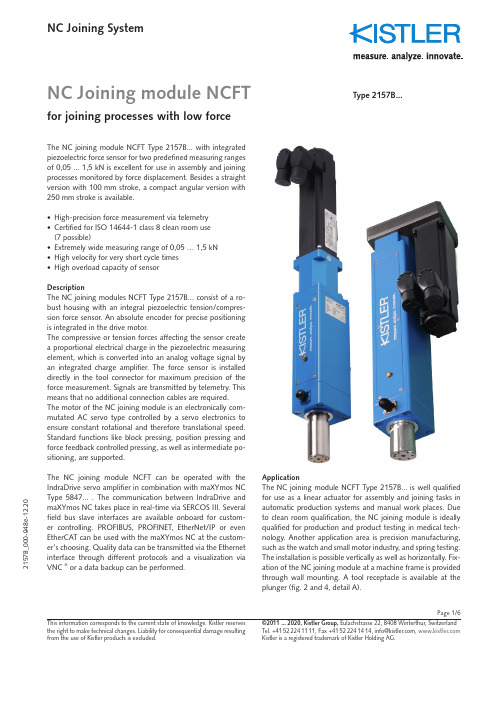
Page 1/6NC Joining module NCFTfor joining processes with low force2157B _000-948e -12.20NC Joining SystemThis information corresponds to the current state of knowledge. Kistler reserves the right to make technical changes. Liability for consequential damage resulting ©2011 ... 2020, Kistler Group, Eulachstrasse 22, 8408 Winterthur, Switzerland The NC joining module NCFT Type 2157B... with integrated piezoelectric force sensor for two predefined measuring ranges of 0,05 ... 1,5 kN is excellent for use in assembly and joining processes monitored by force displacement. Besides a straight version with 100 mm stroke, a compact angular version with 250 mm stroke is available.• High-precision force measurement via telemetry • Certified for ISO 14644-1 class 8 clean room use (7 possible)• Extremely wide measuring range of 0,05 … 1,5 kN • High velocity for very short cycle times • High overload capacity of sensorDescriptionThe NC joining modules NCFT Type 2157B... consist of a ro-bust housing with an integral piezoelectric tension/compres-sion force sensor. An absolute encoder for precise positioning is integrated in the drive motor.The compressive or tension forces affecting the sensor create a proportional electrical charge in the piezoelectric measuring element, which is converted into an analog voltage signal by an integrated charge amplifier. The force sensor is installed directly in the tool connector for maximum precision of the force measurement. Signals are transmitted by telemetry. This means that no additional connection cables are required. The motor of the NC joining module is an electronically com-mutated AC servo type controlled by a servo electronics to ensure constant rotational and therefore translational speed. Standard functions like block pressing, position pressing and force feedback controlled pressing, as well as intermediate po-sitioning, are supported.The NC joining module NCFT can be operated with the IndraDrive servo amplifier in combination with maXYmos NC Type 5847... . The communication between I ndraDrive and maXYmos NC takes place in real-time via SERCOS III. Several field bus slave interfaces are available onboard for custom-er controlling. PROFI BUS, PROFI NET, EtherNet/I P or even EtherCAT can be used with the maXYmos NC at the custom-er's choosing. Quality data can be transmitted via the Ethernet interface through different protocols and a visualization via VNC ® or a data backup can be performed.Type 2157B...ApplicationThe NC joining module NCFT Type 2157B... is well qualified for use as a linear actuator for assembly and joining tasks in automatic production systems and manual work places. Due to clean room qualification, the NC joining module is ideally qualified for production and product testing in medical tech-nology. Another application area is precision manufacturing, such as the watch and small motor industry, and spring testing.The installation is possible vertically as well as horizontally. Fix-ation of the NC joining module at a machine frame is provided through wall mounting. A tool receptacle is available at theplunger (fig. 2 and 4, detail A).Page 2/62157B _000-948e -12.20This information corresponds to the current state of knowledge. Kistler reserves the right to make technical changes. Liability for consequential damage resulting ©2011 ... 2020, Kistler Group, Eulachstrasse 22, 8408 Winterthur, Switzerland Tel.+41522241111,Fax+41522241414,****************, Technical dataDimensions mm Fig. 1 to 4Assembly options wall assembly Weight (straight NCFT) kg 5,8Weight (angular NCFT) kg 7,8Max. tool weight 1)kg 5Direction of measurement compress./tens.Measuring range kN 0,05 kN 0,1 kN 0,25 kN 0,5 kN 1,0 kN 1,5Length of stroke (straight NCFT) mm 100Length of stroke (angular NCFT) mm 250Tool holder mm Fig. 2, 4, detail A Holding brake V/A 24/0,4Max. movement speed mm/s 400Displacement sensor system absolute encoderResolution µm 0,2Practical repeatability mm <0,002Practical repeatability 2157B...T250 mm <0,01Force sensor piezoelectric Temperature range °C 10 ... 40Protection class IP54Linearity in all ranges %FSO ≤1Accuracy class force sensor % 0,5Service life of spindle cycles >10 Mio. (acc. to defined drive profile) Short stroke mm ≤60Lubrication connection standard- (internal) lubrication nipple Servo amplifier 2) Bosch-Rexroth Type 2180...Standard interface SERCOS III (internal bus)Evaluation unit 3) maXYmos NC Type 5847...Standard Interface PROFIBUS, PROFINET, EtherNet/I P , EtherCAT Power supplyVDC 24 ±5 %1)Attention must be paid to possible radial forces independent of the instal-lation position. Permissible tool weight may have to be reduced for manualfeed.A bending of the plunger depending on the tool weight must be considered for a horizontal installation.2) Servo amplifier see accessories data sheet 003-125 Type 2180... 3)Evaluation unit maXYmos NC Type 5847B... see data sheet 003-272Page 3/62157B _000-948e -This information corresponds to the current state of knowledge. Kistler reserves the right to make technical changes. Liability for consequential damage resulting ©2011 ... 2020, Kistler Group, Eulachstrasse 22, 8408 Winterthur, Switzerland Tel.+41522241111,Fax+41522241414,****************, Connection force sensorPage 4/6This information corresponds to the current state of knowledge. Kistler reserves the right to make technical changes. Liability for consequential damage resulting ©2011 ... 2020, Kistler Group, Eulachstrasse 22, 8408 Winterthur, Switzerland Tel.+41522241111,Fax+41522241414,****************,3 5Page 5/6NC joining module NCFT for joining processes with low forces, Type 2157B... 2157B _000-948e -12.20This information corresponds to the current state of knowledge. Kistler reservesthe right to make technical changes. Liability for consequential damage resulting ©2011 ... 2020, Kistler Group, Eulachstrasse 22, 8408 Winterthur, Switzerland Tel.+41522241111,Fax+41522241414,****************, Fig. 5: Functional principle of NC joining system with NC joining module NCFT Type 2157B... and maXYmos NC Type 5847...Included accessories• NoneOptional accessories Type/Art. No.• Evaluation unit maXYmos NC 4)(MEM) 5847...• B earing rail adapter for 35 mmCap rail including 2 fastening screws M3x10 5700A31• Display module (DIM) with pedestal 5877AZ000• Connection cable maXYmos MEM on DIM, length 5 m 1200A161A5• Servo amplifier 2)2180...Cable Type/Art. No.• NCFT motor cable,length 5 m RKL4302 KSM315330-5• NCFT MSK Feedback cable,length 5 m RKG4200 KSM303500-5• maXYmos Force transmitter cable, length 5 m KSM18028884-5• SERCOS III connection cable, length 5 m KSM18029160-5• Safety zone box cable, 2 cables required), length 1 m KSM18029161-1Other length on request.Functional principle with maXYmos NC Type 5847...2)Servo amplifier see accessories data sheet 003-125 Type 2180A...4)Evaluation unit maXYmos NC Type 5847B... see data sheet 003-272IndraDriveMotoransteuerung KSM18029160-5zonenmodul (Kabellänge max. 5 m)Sicherheitszonenbox KSM18029161-1LadungsverstärkerKonfiguration, ParametrierungBewertung und Visualisierung maXYmos NC Typ 5847A...box safety zone box KSM18029161-1KSM18029160-5Motor Control Configuration, parameterization, evaluation and visualization maXYmos NC Type 5847...1200A161A...(Cable length max. 5 m)Threaded spindle drive AC servo motor Absoulte encoder Piezoelectric force sensor Charge amplifierOrdering key servo amplifier for NCFTPage 6/6NC joining module NCFT for joining processes with low forces, Type 2157B...2157B _000-948e -12.20This information corresponds to the current state of knowledge. Kistler reserves the right to make technical changes. Liability for consequential damage resulting ©2011 ... 2020, Kistler Group, Eulachstrasse 22, 8408 Winterthur, Switzerland Tel.+41522241111,Fax+41522241414,****************,Application exampleFig. 8: Detail view w atch-and-clock industryFig. 6: Application example for the watch-and-clock industryFig. 7:Testing an inhalerOrdering keyType 2157BOrdering example (straight version) Type 2157B5NC joining module NCFT T ype 2157B..., measuring ran- ge 1: 1 kN , measuring range 2: 0,25 kN , choice: 5Ordering example (angular version) Type 2157B5T250NC joining module NCFT T ype 2157B..., measuring ran- ge 1: 1 kN , measuring range 2: 0,25 kN , choice: 5, stroke 250 mm (angular) T250。
深圳市芯中芯科技有限公司蓝牙模块F-6988 V3.1产品规格书说明书

F-6988 V3.1 产品规格书Specification产品名称Product name : 蓝牙模块Bluetooth module产品型号Product model:F-6988 V3.1文件编号Document No:XZX-SPEC-BT-RD-023文件版本Document Version:V2.5生效日期Availability date:2018-7-11文件含芯中芯(C-CHIP)机密文件,未经许可,不可外传File include (C-CHIP) confidential documents, without permission, can not be disclosedF-6988 V3.1目录(Content)一、产品概述Product overview: (4)二、应用领域A pplication area: (4)三、基本特性Features: (5)四、性能参数performance parameter: (5)五、方框图Module block diagram (6)六、模块尺寸图The size of the module graph: (7)七、模块的封装物料高度尺寸Module packaging material height dimensions: (8)八、引脚功能说明Pin definition: (9)九、电路连接注意Design notes: (11)十、注意事项Note: (11)十一、推荐回流温度Recommended reflow temperature: (12)F-6988 V3.1 一、产品概述Product overview:F-6988 蓝牙模块为本公司自主开发的智能型无线音频数据传输产品,是低成本的高性价比的立体声无线传输方案,模块采用了 BEKEN 的BK3266 芯片 QFN32 封装设计。
F-6988 蓝牙模块采用免驱动方式,客户只需要把模块接入应用产品,就可以快捷地实现音乐的无线传输,享受无线音乐的乐趣,而且支持简单的数据传输功能。
汇承hc-05蓝牙模块用户手册(中文版)

HC-05蓝牙串口通信模块用户手册V2.1Rev22.1~2016/2/222016/2/22~2.0 2.1DRAWN BY:Ling Xin MODEL:HC-05(主从一体) CHECKED BY:Eric Huang描述:BC04外置8M Flash模块APPD.BY:SimonMokUART(默认)9600蓝牙模块HC-05、HC-06、HC-08无线模块HC-11、HC-12带底板模块参数架HC-USB-PPIN(默认)1234USB转TTL接口HC-05-USB、HC-06-USB HC-11-USBMODE(默认)从机新版模块带有蓝牙指示灯(靠近模块第1脚)。
模块的22脚LED_CON是指示灯控制脚,该脚接地,蓝牙指示灯关闭;该脚悬空,蓝牙指示灯亮。
如果要调整灯的亮度,可以在该脚接一个1K~47K的电阻到模块的31脚LED1,电阻越小,灯越亮。
贴片炉温参考建议首次大批量贴片生产的厂家,先过炉20~30片模块,检查炉温是否合适建议贴片锅炉炉温不得超过参考图温度,二次贴片降低5度左右,夏天可以再适当降低温度供电电压3.1~4.2V工作电流不大于50mA(以实测为准)尺寸大小27mm*13mm*2mm存储温度:-40℃至+85℃,工作温度:-25℃至+75℃数字2.4GHz无线收发射内置2.4GHz天线,用户无需调试天线蓝牙2.0,2Mbps空中波特率CSR BC04蓝牙芯片技术支持Android、WINXP、WIN7数据收发通过UART串口收发HC-05封装下载:/downloadDis.asp?id=15安卓串口助手APP下载:/downloadDis.asp?id=49 PC串口助手下载:/downloadDis.asp?id=44注:蓝牙模块的PIN2:UART-RXD不带上拉,如果单片机TXD无上拉能力的话需要在模块的UART-RXD脚上接个上拉电阻,这个很容易被用户忽略。
因为内容较长,请参考公司网站下载中心提供的文档HC-05AT指令集下载:/downloadDis.asp?id=64。
BCM20730蓝牙模块规格书

Contents1.Overview....................................... .. (3)2.Applications (3)3.Features (3)4.Block Diagram (4)5.Module Picture (4)6.Packing (5)7.Module Dimension (6)8.Pin Description (8)9.Technical Specifications (8)9.1General Specification (8)9.2Electrical Characteristics (9)10. Function Test (11)1.OverviewThe BCM20730 is a Bluetooth Human Interface Device (HID) Module baseon Broadcom BCM20730 Bluetooth controller. It is integrated with PCBantenna, serial EEPROM, Crystal, and also components for the built-inswitching regulators to reduce the external BOM cost.The BCM20730 Module has been designed to provide low power, low cost,and robust communications for applications operating in the globallyavailable 2.4GHz unlicensed ISM band. It is fully compliant withBluetooth Radio Specification 3.0.2.Applications• Wireless pointing devices: Mouse, trackballs, gestural controls• Wireless keyboards• 3D glasses• Remote controls• Game controllers• Point-of-sale(POS) input device• Remote sensors• Home automation• Personal health and fitness monitoring3.Features• Bluetooth V3.0 specification compatible, including enhanced powercontrol (Unicast Connectionless Data)• Bluetooth HID profile V1.0 compliant• Bluetooth Device ID profile version 1.3 compliant• Bluetooth AVRCP-CT profile version 1.3 compliant•Programmable output power control meets Class 2 and Class 3 requirements • Ultra low power design• Support AFH(Adaptive Frequency Hopping)• Enhanced power control• Shutter control for 3D glasses• Infrared modulator• Triggered Broadcom Fast Connect• Slim printed with 30mm*14mm*0.8mm• ROHS compliant• BQB certification6. PackingFinished product packing use the blister-tray4. Block Diagram5. Module Picture7.Module DimensionDimension: 30mm*14mm*0.8mm8.Pin Description9. Technical Specifications9.1 General Specification9.2 Electrical Characteristics10. Function Test10.1 客户要求平台测试:10.2 客户的Key matrix layout测试10.3 蓝牙设备搜索名称是否正确(客户要求):PASS□ FAIL□10.4 指示灯的状态是否正确(客户要求):PASS□ FAIL□ 无指示□10.5 键盘NumLock,ScrollLock,CapsLock指示灯是否与主机同步:PASS□ FAIL□ 无指示□10.6 休眠时间是否正确(客户要求):PASS□ FAIL□10.7 低电压报警电压/关机电压(客户提供):PASS□ FAIL□10.8 操作距离测试(符合CLASS2要求无障碍物测试有效距离10米以上):PASS□ FAIL□。
ZX-D50 接近开关蓝牙模块技术手册说明书
ZX-D50接近开关蓝牙模块技术手册版本:V1.2日期:2022/11/22目录1模块介绍 (2)1.1概述 (2)1.2特性 (2)1.3应用 (3)1.4基础参数表 (3)1.5工作电流参数表 (3)1.6出厂默认配置参数 (4)2应用接口 (5)2.1模块引脚定义 (5)2.2引脚功能表 (5)2.3特殊引脚IO功能表 (6)2.4电源设计 (6)2.5串口电平转换参考电路 (7)2.6应用原理图 (8)2.7外形尺寸 (9)3回流焊曲线图 (10)4Layout注意事项 (10)5AT指令集 (12)6微信小程序使用说明 (19)7更新记录 (20)8联系我们 (20)9免责申明和版权公告 (20)1.1概述1.2特性●CPU:Embedded 32-bits Processor ●内存大小:256KB FLASH+128KB RAM ●蓝牙BLE5.1●功耗可低至620uA ●工作频率:2.4GHZ ●可视距离:50M●传输速率:250Kbps/1Mbps/2Mbps ●发射功率:-20dBm~10dBm ●接收灵敏度:-95dBm●支持UART,IIC,SPI,GPIO 硬件接口●工作温度:-40℃~+105℃●天线采用板载天线+外置ipex 天线ZX-D50是深圳市智兴微科技有限公司专为接近开关应用打造的一款低功耗蓝牙模块,该模块为蓝牙5.1协议,具有极好的额稳定性和兼容性。
模块支持系统蓝牙直接连接,无感自动回连,无需APP。
支持点动、常通模式,支持微信小程序修改蓝牙名、配对密码、连接距离等参数。
1.3应用●智能门锁●汽车无钥匙进入●自动感应开关1.4基础参数表参数名描述参数名描述型号ZX-D50模块尺寸15×20x2.3mm 蓝牙版本BLE5.1通信距离50M工作频段 2.402GHz-2.480GHz ISM band串口透传速率BLE20KB/S+工作电压 2.5V~4.3V功能串口透传/接近开关外设接口UART/I2C/ADC/GPIO天线板载/外置ipex 调制方式GFSK工作温度-40℃~+105℃1.5工作电流参数表工作模式状态平均电流广播状态(低功耗模式)50ms广播间隔(非低功耗模式)6.3mA 50ms广播间隔(低功耗模式)1.5mA 500ms广播间隔(低功耗模式)620uA连接状态非低功耗模式 6.3mA 低功耗模式 1.4mA注:出厂默认广播间隔时间为50ms,对低功耗有需求的可适当加大广播间隔时间。
深圳市昇润科技HY-40R201低功耗蓝牙5.0模块规格书说明书

HY-40R201深圳昇润科技对本手册中可能出现的和/或规格书的权利,恕不另行通知用作生命支持设备或系统中的关键标是由美国蓝牙SIG公司所有.R201低功耗蓝牙 5.0模块规格书(40 pin)文档版本:V2.02017年10月25日深圳市昇润科技有限公司版权所有现的错误不承担责任。
此外,昇润科技保留随时行通知,并不承诺更新此处所包含的信息。
昇润的关键组件。
以及不承担各种专利或知识产权的.密级:公开资料留随时更改硬件,软件。
昇润的产品不被授权产权的授权使用;蓝牙商1.简述 (1)1-1应用: (1)1-2主要特征: (1)2. 产品型号 (2)2-1.(4 种天线形式可供选择)/( 可选: 带屏蔽罩或不带屏蔽罩) (2)2-2: HY-40R201PC机种屏蔽罩上FCC ID &( IC ID 待定义)印刷内容: (2)3. 模块尺寸与图片 (2)3.1 HY-40R201P / WMD40R201SR6P0 PCB IFA天线 (2)3-2.HY-40R201I /WMD40R201SR6I0 IPEX RF外接天线连接端子 (3)3-3. HY-40R201W / MD40R201SR6W0 金属线天线 (1/4波长偶极子天线) (3)3.4. HY-40R201C/ WMD40R201SR6C0 (陶瓷天线) (3)(4). 应用注意事项: (4)5.引脚分配和端口功能说明 (5)6. 电气特性 (6)6-1. 射频特性 及 电流功耗: (6)6-2. 绝对最大额定值 (7)6-3. ESD 额定值 (7)6-4.建议工作条件 (7)6-5.GPIO DC特性 (7)6-6. 时序要求 (8)6-7. 动作状态切换时序特性 (8)7. 模块方块图 (8)8.IC功能方块图 (9)9. 工作模式架构图 (9)10. 回流焊曲线建议 (无铅锡膏: Sn 96.5%, Ag 3%, Cu 0.5%) (10)11. HY-40R201PC / WMD40R201SR6PC 模块 FCC及 IC声明 (11)12.联系我们 (13)HY-40R201提供蓝牙低功耗特性:无线电,蓝牙协议栈,配置文件和客户应用程序的所需空间。
蓝牙语音遥控器 BT-XM-15 产品规格书和使用手册说明书
2.2 供电说明 Power supply instructions.............................................................................................5 2.2.1 电池规格 Battery specifications .........................................................................................5 2.2.2 工作模式 Operating mode..................................................................................................5 2.2.3 休眠机制 Hibernation mechanism....................................................................................6
PANASONIC PAN1740蓝牙模块设计指南说明书
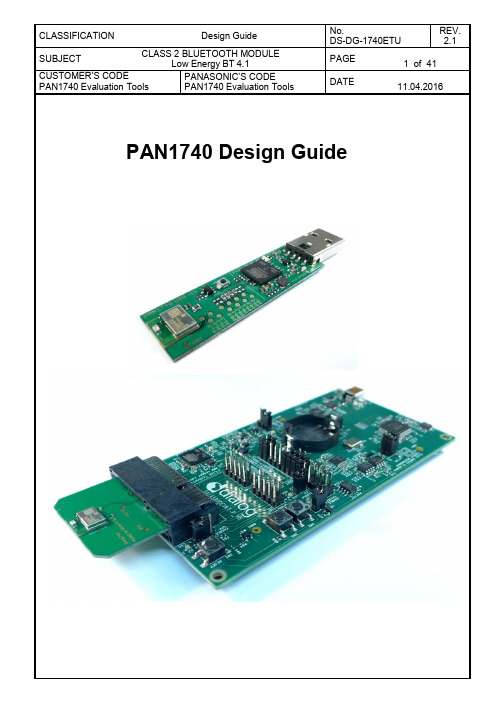
6.1.FunctionalityAtmel µC includes Segger USB-to-UART programmer (serial number on the backside) OTP cannot be damaged - Failsafe development Runs with Dialog ’s Keil compiler projects Runs with "Connection Manager"USB >> UART by Segger SN ModuleBreak Out SectionLDO Power Supply USB -5V1.1.FunctionalityAtmel µC includes Segger USB-to-UART programmer (serial number on the backside) OTP cannot be damaged - Failsafe development Runs with Dialog ’s Keil compiler projects Runs with "Connection Manager"USB >> UART by Segger SN ModuleBreak Out SectionLDO Power Supply USB -5V2.1. Functionality3.1. SchematicPCI-E-64PCI-E-64V C CV C CV C Cn .c ./0VCC VPP SW_CLK SW_DIOP0.012P0.111P0.210P0.39P0.46P0.55P0.64P0.73P1.024P1.123P1.222P1.321N.C.13RST 2GND GND GND GND GND GND GND GND GND GNDMOD1PAN1740A1A2A3A4A5A6A7A8A9A10A11A12A13A14A15A16A17A18A19A20A21A22A23A24A25A26A27A28A29A30A31A32J1_AB1B2B3B4B5B6B7B8B9B10B11B12B13B14B15B16B17B18B19B20B21B22B23B24B25B26B27B28B29B30B31B32J1_BR 11JP1P0.0P0.0P0.1P0.1P0.2P0.2P0.3P0.3P0.4P0.4P0.5P0.5P0.6P0.6P0.7P0.7P1.0P1.0P1.1P1.1P1.2P1.2P1.3P1.3RSTRST VPP SWCLK SWDIO Reset PIN resistor is not mounted if the module is empty4.1. SchematicB S S 84W 0.1n.c./0Ohm VCC 8VPP 14SW_CLK 16SW_DIO18P0.012P0.111P0.210P0.39P0.46P0.55P0.64P0.7324GND 1GND 715MOD1PAN1740Q 1C2R1VBA VEEPROMP0.0P0.1P0.2P0.3P0.4P0.5P0.6P0.7P1.0VPP SW_CLK SW_DIOThe Beacon-Kit consists of:The Beacon software is stored in the SPI Flash (IC2) on the PCB and can be changed bybetween Dialog’s Motherboard and a BeacAdapter Board and the FFC as shown below.An FFC longer than 5cm can cause transmission errors when using JTAG. Hence, longer cables should use the UART interface to download software to the Beacon. Simply change Dialog’s Beacon code available on our website to your needs with KeilNote: The above recommendation for the Ground plane is based on a double layer PCB. If7.4.3. IPhone Demo“Bluetooth Smart Scanner” may be replaced by other BLE Apps for Android or WindowsOpen the proximity project example found in the Dialog SDK. The project is located in theClick the Debug tab. Setup the Port in the J-Flash Settings to “SW”. Press “OK”.The proximity project has now been compiled and downloaded into the RAM of theNote: Debug session must be stopped.Transmitter Configuration:The dongles are now connected with the proximity profile.When the application launches the first time, there will be no projects to select. The user will have to create one by pressing the “New” button. The name should not contain any spaces or special characters.After selecting a project, the user will have to select the DA14580 chip version and a virtual COM port which is assigned to the connected dialog development kit.Finally, the user needs to press Open to establish a connection to the development kit. TheThis previous figure from the Smart Snippets help shows an example that prefers theThis pin assignment can be changed to any desired pin assignment in the application source This assignment does only require a simple amendment in the code.The next step is to disable the sleep mode, as this is not fully supported for software flowAfter that, the amended source codes have to be compiled and the output .hex files have toMore details are explained in the help file of Smart Snippets.。
聆思科技 听声 双麦离线语音交互芯片产品规格书说明书
双麦离线语音交互芯片 产品规格书 型号:C4203-L02C文档密级:对外公开 Version 1.2 2021.1.18L I S T E N A I _f o r _L I S T E NAI_for _LISTENAI_for_LISTE N A I _f o r _L I S T E N A I _f o r _LI S T E N A I _f o r _声明 本手册由聆思科技版权所有,未经许可,任何单位和个人都不得以电子的、机械的、磁性的、光学的、化学的、手工的等形式复制、传播、转录和保存该出版物,或翻译成其它语言版本。
一经发现,将追究其法律责任。
聆思科技保证本手册提供信息的准确性和可靠性。
聆思科技保留更改本手册的权利,如有修改,恕不相告。
请在订购时联系我们以获得产品最新信息。
对任何用户使用我们产品时侵犯第三方版权或其它权利的行为聆思科技概不负责。
另外,在聆思科技未明确表示产品有该项用途时,对于产品使用在极端条件下导致一些失灵或损毁而造成的损失概不负责。
L I S T E N A I _f o r _L IS T E NAI_for _LISTENAI_for_LISTE N A I _f o r _L I S T E N A I _f o r _L I S T E N A I _f o r _变更记录L I S T E N A I _f o r _L IS T E NAI_for _LISTENAI_for_LISTE N A I _f o r _r _目录 声明 ............................................................................................................................................................... 1 变更记录 ..................................................................................................................................................... 2 1产品简介 .................................................................................................................................................. 5 1.1 方案介绍 ......................................................................................................................................... 5 1.2 方案特性 ......................................................................................................................................... 5 2产品能力介绍 ......................................................................................................................................... 7 2.1 功能介绍 ......................................................................................................................................... 7 2.2 AI 技术特点 ..................................................................................................................................... 7 2.2.1双麦降噪 ....................................................................................................................................... 7 2.2.2 噪声抑制 ...................................................................................................................................... 8 2.2.3 语音唤醒 ...................................................................................................................................... 8 2.2.4 离线识别 .. (8)2.2.5 播报打断 (8)2.3 效果介绍 (9)3使用场景 (10)4 模组介绍 (11)4.1 模组配置 (11)4.2 系统框图 (12)4.3 芯片框图 (12)4.4 封装 ................................................................................................................................................ 13 L I S T E N A I _f o r _L IS T E NAI_for _L ISTENA I_for_L ISTE N A I _f o r _L I S T E N A I _f o r _L I S T E N A I _f o r _4.5 芯片引脚说明 .............................................................................................................................. 14 4.6 电气特性 ....................................................................................................................................... 15 5 开发流程 ............................................................................................................................................... 16 6 可靠性测试 .......................................................................................................................................... 18 6.1 外观 ................................................................................................................................................ 18 6.2 盐雾测试 ....................................................................................................................................... 18 6.3 高温高湿存储测试 ..................................................................................................................... 18 6.4 温度冲击测试 .............................................................................................................................. 18 6.5 低温存储测试 .............................................................................................................................. 19 6.6 85/85实验 ..................................................................................................................................... 19 6.7 有毒有害物质检测 ..................................................................................................................... 19 6.8 连接测试 ....................................................................................................................................... 19 6.9 振动测试 (19)6.10 高温运行测试 (19)6.11 低温运行测试 (20)6.12 开关机测试 (20)L I S T E N A I _f o r _L IS T E NAI_for _LISTENAI_for_L ISTE N A I _f o r _L I S T E N A I _f o r _L I S T E N A I _f o r _1产品简介 1.1 方案介绍 随着人工智能行业的迅猛发展,人工智能技术开始应用在各种用户场景,智能硬件产品开始逐步普及,走向千家万户。
SJR-BTM308-C蓝牙音频模块
Bluetooth Module DatasheetModel:SJR-BTM308-CVersion:V1.12018-07-05Sky Jiarun Technologies Co.,Ltd.Tel:(0755)85279490E-mail:sales@Web:Fuyong,Baoan,ShenzhenList of Contents1Introduction (3)2Key Features (3)3Applications (4)4Block Diagram (4)5General specifications (4)6Module Package Information (5)6.1Pinout Diagram and package dimensions (5)6.2Module Pin descriptions (6)7Electrical Characteristics (9)7.1Absolute Maximum Ratings (9)7.2Recommended Operating Conditions (9)8Recommended reflow temperature profile (10)1IntroductionSky Jiarun Technologies introduces the pioneer of the Bluetooth5.0modules SJR-BTM308-C which is a high performance,cost effective,low powerand compact solution.The Bluetooth module provides a complete2.4GHzBluetooth system based on the QCC3008QFN chipset which is a singlechip radio and baseband IC for Bluetooth2.4GHz systems,.This module is fullyqualified single-chip dual mode Bluetooth@v5.0system.2Key FeaturesBluetooth Profiles●Bluetooth v5.0specification support●Qualcomm®Bluetooth®Low Energy secure connection●A2DP v1.3.1●AVRCP v1.6●HFP v1.7●HSP v1.2●SPP v1.2●DID v1.3●HOGP v1.0●PXP v1.0.1●FMP v1.0●BAS v1.0●QTIL's proximity pairing and QTIL's proximity connectionMusic Enhancements●aptX,aptX Low Latency,SBC,and AAC audio codecs●Qualcomm TrueWireless™Stereo(TWS),which allows two devices to beconfigured as a stereo pair●Configurable Signal Detection to trigger events●1bank of up to10-stage Speaker Parametric EQ●6banks of up to5-stage User Parametric EQ for music enhancement●Qualcomm®meloD™Expansion audio processing:3D stereo widening●Compander to compress or expand the dynamic range of the audio●Post Mastering to improve DAC fidelity●Dual I²S outputs with crossoverAdditional Functionality●Support for multi-language programmable audio prompts●Multipoint support for A2DP connection to2A2DP sources for music playback●Talk-time extension,which automatically reduces processor functions to extenduse when a low battery condition is detected●Slim module with13.5mm x21mm x2.0mm3Applications●Stereo Headsets●Wired Stereo headsets and headphones●Portable Bluetooth Stereo speakers4Block Diagram5General specificationsModel Name SJR-BTM308-CProduct Description Bluetooth5.0Class2Module Bluetooth Standard Bluetooth5.0Chipset QCC3008QFNDimension13.5mm x21mm x2.0mmOperating ConditionsVoltage 2.8~4.2VTemperature-10~+70℃Storage Temperature-40~+85℃Electrical SpecificationsFrequency Range2402~2480MHzMaximum RF Transmit Power9dBmπ/4DQPSK Receive Sensitivity-92dBm8DPSK Receive Sensitivity-82dBm6Module Package Information6.1Pinout Diagram and package dimensionsUnit:MMRecommended PCB layout footprint6.2Module Pin descriptionsPin#Pin Name Pin TypeDescription1GND GroundGround2AIO_0Analogue input/output Analogue programmable input/output line 0.3NC NC NC 4NCNCNC5UART_RTS/PIO_16Bidirectional with strong pull-upUART request to send,active low Alternative function:■PIO_16Programmable input/output line 16.6UART_CTS/PIO_17Bidirectional with strong pull-down UART clear to send active lowAlternative function:■PIO_17Programmable input/output line17.7NC NC NC 8NC NC NC 9NC NC NC 10NC NC NC 11NC NC NC12SPI_PCM Input with weak pull-down SPI/I2S#select input ■0=I2S/PIO interface ■1=SPI13GND Ground Ground14SPI_MISO Bidirectional with weak pull-down SPI data outputAlternative function:■PIO_3:Programmable input/output line3.■I2S1_SD_OUT:I2S1synchronous data output15SPI_MOSI Bidirectional with weak pull-down SPI data inputAlternative function:■PIO_2:Programmable input/output line ■SPDIF_IN:SPDIF input■I2S1_SD_IN:I2S1synchronous data input16SPI_CLK Bidirectional with weak pull-down SPI clockAlternative function:■PIO_5:Programmable input/output line ■I2S1_CLK:I2S1synchronous data clock17SPI_CSB Bidirectional with weak pull-down Chip select for SPI,active lowAlternative function:■PIO_4:Programmable input/output line4.■I2S1_WS:I2S1word select18GND Ground Ground19GND Ground Ground20BT_Reset Input with strong pull-up Reset if low.Pull low for minimum5ms to cause a reset 21GND Ground Ground22LED_1Bidirectional Open-drain output23LED_0Bidirectional Open-drain output24PWR CMOS Input Regulator enable and multifunction button.A high input(tolerant to VBAT voltages)enables theon-chip regulators,which can then be latched on internally and the button used as a multifunction input.25GND Ground Ground26VBUS Charge input Charge input.Typically connected charger27CHG_EXT Exernal battery charger control External battery charger transistor base control when using external charger boost.Otherwise leave unconnected.28VBAT_SENSE CMOS Input Battery charger sense input.29VBAT Power Input Positive supply for BT Module,or batterypositive terminal30GND Ground Ground311V8Power output Auxiliary regulator output(1.8V out)32VDD_PADS Power input Positive supply input for input/output ports 333V3_USB Power output 3.3V bypass linear regulator output34GND Ground Ground35USB_N Bi-directional USB data minus36USB_P Bi-directional USB data plus with selectable internal1.5kΩpull-up resistor37GND Ground Ground38PIO_9Bidirectional with strong pull-down Programmable input/output line9. Alternative function:■UART_CTS:UART clear to send,active low ■I2S2_SD_IN:I²S2synchronous data input39PIO_0Bidirectional with strong pull-up Programmable input/output line0. Alternative function:■UART_RX:UART data input40PIO_1Bidirectional with strong pull-up Programmable input/output line1. Alternative function:■UART_TX:UART data output41PIO_8Bidirectional with strong pull-up Programmable input/output line8.Alternative function:■UART_RTS:UART request to send,active low ■I2S2_SD_IN:I²S2synchronous data input42PIO_7Bidirectional with strong pull-down Programmable input/output line7.■I2S2_WS:I2S2word select43PIO_6Bidirectional with strong pull-down Programmable input/output line6.■I2S2_SD_OUT:I2S2synchronous data output 44PIO_21Bidirectional with weak pull-down Programmable input/output line21.45PIO_18Bidirectional with weak pull-down Programmable input/output line18.46LED_2Bidirectional Open-drain output47GND Ground Ground48MIC_BIAS Analogue Microphone bias49LINE/MIC_AN Analogue in Microphone input negative,channel A50LINE/MIC_AP Analogue in Microphone input positive,channel A51LINE_BN Analogue in Line-in negative,channel B52LINE_BP Analogue in Line-in positive,channel B53GND Ground Ground54SPK_RN Analogue OUT Speaker output negative,right55SPK_RP Analogue OUT Speaker output positive,right56SPK_LN Analogue OUT Speaker output negative,left57SPK_LP Analogue OUT Speaker output positive,left58GND Ground Ground59RF_IN RF Bluetooth50Ωtransmitter output/receive input 60GND Ground Ground7Electrical Characteristics7.1Absolute Maximum RatingsRating Minimum MaximumStorage temperature-40℃+85℃7.2Recommended Operating ConditionsOperating Condition Minimum MaximumOperating temperature range-10℃+70℃Supply voltage:VBAT+2.8V+4.2V8Recommended reflow temperature profileThe module Must go through125℃baking for at least9hours before SMTAND IR reflow process!若拆封后未立即上线,天嘉润科技建议让下次上线前务必以125℃烘烤9小时以上!11Record of ChangesIMPORTANT NOTICESky Jiarun Technologies Co.,Ltd (SJR)reserve the right to make changes to their products or to discontinue any product or service without notice,and advise customers to obtain the latest version of relevant information to verify,before placing orders,that information being relied on is current.All products are sold subject to the SJR terms and conditions of sale supplied at the time of order acknowledgement,including those pertaining to warranty,patent infringement,and limitation of liability.SJR warrants performance of its products to specifications applicable at the time of sale in accordance with SJR’s standard warranty.Testing and other quality control techniques are utilized to the extent SJR deems necessary to support this warranty.Specific testing of all parameters of each device is not necessarily performed,except those mandated by government requirements.In order to minimize risks associated with customer applications,adequate design and operating safeguards must be used by the customer to minimize inherent or procedural hazards.SJR products are not authorized for use as critical components in life support devices or systems without the express written approval of an officer of the company.Life support devices or systems are devices or systems that are intended for surgical implant into the body,or support or sustain life,and whose failure to perform when properly used in accordance with instructions for use provided,can be reasonably expected to result in a significant injury to the user.A critical component is any component of a life support device or system whose failure to perform can be reasonably expected to cause the failure of the life support device or system,or to affect its safety or effectiveness.SJR assumes no liability for applications assistance or customer product design.SJR does not warrant or represent that any license,either express or implied,is granted under any patent right,mask work right,or other intellectual property right of SJR covering or relating or any combination,machine,or process in which such products or services might be or are used.Tel:(0755)85279490Fax :(0755)85279683Web:E-mail:sales@ DataRevision Description 2018-01-30V1.0Original publication of this document.2018-07-05V1.1Fix PIN definition.。
BC05 立体声蓝牙模块规格书

四.产品方块图:
VTL-1698A
cyd16988@
五.尺寸标注:
VTL-1698A
cyd16988@
VTL-1698A
六.管脚说明:
管脚号
名称
1,21,32,40,43, 48,56,58
GND
2
PIO1
3
PIO0
串口输出端 串口输出端 数字 IO 口 数字 IO 口 数字 IO 口 数字 IO 口 数字 IO 口 数字 IO 口 数字 IO 口 低电平复位端 调试端口 调试端口 调试端口 调试端口 接红色 LED,显示电源相关信息 接蓝色 LED,显示蓝牙工作状态相关信息 开关机/接听电话等多功能按键输入端 内置 DC-DC 输出电压,供主芯片使用,尽量不要外接其他器件以防干扰 电池供电(3.3-4.2V) 充电端口(5V) 左声道音频输差分出端 左声道音频输差分出端 右声道音频输差分出端 右声道音频输差分出端 右声道 MIC 差分输入端 右声道 MIC 差分输入端 左声道 MIC 差分输入端 左声道 MIC 差分输入端 MIC 工作偏置电压 数字 IO 口 数字 IO 口 天线接口
36
LED1
37
LED0
38
VREN
39
1.8V
41
VBAT
42
V_CHG
44
SPK_A_P
45
SPK_A_N
46
SPK_B_P
4MIC_B_P
50
MIC_B_N
51
MIC_A_P
52
MIC_A_N
53
MIC_BIAS
54
PIO3
55
PIO2
57
ANT
BT1200蓝牙模块规格书1.1
深圳市百泰实业有限公司Product SpecificationModel : BT1200REV : 1.1DRAWN BY :CHECKED BY :APPD. BY:一、功能特性• 支持V2.0+EDR版蓝牙规范• 输出功率类别为Class 2(Bluetooth radio with +2dBm transmit power and-83dBM receive sensitivity)• 支持A2DP立体声播放(supports A2DP V1.2 and AVRCP V• 模块专为蓝牙音箱类产品应用而设计• 规格尺寸:21mm x 21mm x 2.0mm1.1 radio• Bluetooth V2.0 + EDR specification compliant system in 2.4GHz ISM band• typical +2 dbm transmit power• typical -83 dBm receive sensitivity• on-chip Bluetooth stack allows full-speed data transfer and Piconet support• on-chip A2DP V1.2 and AVRCP V1.4 profiles with hardware SBC decoder enables audiostream over Bluetooth and remote control1.2. baseband processor• on-chip low power, high performance, 32-bit RISC processor• 2Mb internal ROM and 48kB internal RAM• integrated one-time programmable (OTP) ROM for device configuration data• fully integrated Bluetooth baseband logic for FEC, HEC, access code correlation, CRC, demodulation, encryption bit stream generation, whitening• fully supports Bluetooth V2.0 + EDR features including AFH and enhanced datarate up to 3Mbps• supports CVSD transcoder for voice over air1.3 stereo audio CODEC• integrated high fidelity audio CODEC with SNR > 90dB playback• on-chip 20-bit stereo audio digital-to-analog converter (DAC)• on-chip 16-bit mono voice analog-to-digital converter (ADC)• integrated headphone amplifier in 40mW @ 32Ω supporting capacitor-less output• one-channel microphone input with microphone driver二、规格说明2.1 transmitter characteristics2.2 receiver characteristics2.5 digital to analog converter characteristicsa2.6 POWER CONSUMPTION 功耗测试NOMINALLIMIT55≦702.7 COMMUNICATION RANGE 通信距离NOMINALLIMIT8+/-1/8-122.8电性参数4.2VMin-40°C Max +100°C90% Min -10°C 3.3VMax +80°C mAUNIT正常通信距离(直线无障碍物)M 最大通信距离(直线无障碍物)MUNITplay MODE CURRENT 音乐电流(最大音量档)存储条件DESCRIPTIONDESCRIPTION存储温度 相对湿度建议工作条件 工作温度范围 工作电压(VCC)0%三、功能方块图表四、PIN脚功能说明PIN脚编号123、222145678PLAY/PAUSE 播放/暂停按键信号9NEXT 下一曲10PREVIOUS 上一曲11VOL+12UART接收信号13VBUCK 内部电源输出脚1415、19、23161817、20空脚BAT_IN 电池电源输入端(3.3-4.2V)注意:电源电压不可超过4.3V GND接地端MIC MIC输入R声道音频输出LED驱动输出(blue)功能说明开关机按键信号L声道音频输出音频输出公共端LED驱动输出(red)ONKEYAudio_COM Audio_R-LED-RED RESET UART_RX UART_TXNCLED-BLUE Audio_L 名称复位控制输入(低电平有效)音量减按键信号/复用上一曲UART发送信号VOL-音量加按键信号/复用下一曲。
SMA-C04产品规格书说明书

SMA-C04 产品规格书版本V1.0版权© 2018关于本手册本手册介绍了SMA-C04模块产品特性、电气特性、管脚布局及定义、功能描述、射频指标、尺寸图,包含以下章节。
章标题内容第1章产品简介概述SMA-C04模块的特点和应用第2章产品展示展示实际产品图片及特性说明第3章电气特性列出产品的基本参数第4章管脚定义提供管脚布局、定义及管脚功能说明第5章功能描述模块功能描述及具体说明第6章射频指标提供模块射频特性表第7章尺寸图提供了模块的尺寸图发布说明日期标题发布说明编制审核2018.3.24 V1.0 首次发布张少茹武鹏飞1. 产品简介SMA-C04是一款基于ESP8285的超低功耗的Wi-Fi四通道开关模块,拥有业内极富竞争力的封装尺寸和超低能耗技术,专为移动设备和物联网应用设计,可将用户的物理设备连接到Wi-Fi无线网络上,进行互联网或局域网通信,实现联网功能。
该模块可以作为4个家用电器的开关控制。
既可以通过本地的按键控制,也可以通过连接APP (易微联)远程控制。
SMA-C04可广泛应用于智能电网、智能交通、智能家具、手持设备、工业控制等领域。
2. 产品展示图 1 SMA-C04正面展示图 2 SMA-C04反面展示产品特性● 3.3VDC供电,最大工作电流210mA;●内置32位MCU,可兼作应用处理器;●支持无线802.11 b/g/n 标准;●************,支持WPA/WPA2 安全模式;●802.11b 模式下+20.5dBm的输出功率;●四通道控制;●支持本地硬件开关控制;●支持Wi-Fi远程控制;●APP支持安卓、iOS系统;●主要应用领域:智能电网、智能交通、智能家居、手持设备及工控领域。
3. 电气特性3.1 额定参数条件:VDD=3.3V±10%,GND=0V;室温25°C下测试。
表 1 额定参数说明类型参数模块型号SMA-C04主芯片ESP8285硬件参数硬件接口UART,GPIO工作电压 2.7V~3.6VGPIO驱动能力Max:12mA工作电流平均电流:≈80mA最大工作电流:210mA待机:<200uA工作温度-40℃~125℃存储环境温度:<40℃,相对湿度:<90%RH 尺寸大小15mm×15mm×1.0mm软件参数无线网络类型STA/AP/STA+AP安全机制WEP/WPA-PSK/WPA2-PSK 加密类型WEP64/WEP128/TKIP/AES 固件升级OTA远程升级3.2 Wi-Fi参数条件:VDD=3.3V±10%,GND=0V;室温25°C下测试。
蓝牙GPS接收器说明书(优选)word资料

蓝牙GPS接收器说明书(优选)word资料BTGP38-Plus 蓝牙GPS接收器说明书Ver3.11.视图A.外观及功能Power button:电源开关Bluetooth Status Led:蓝牙状态指示灯GPS Status Led:GPS 状态指示灯Power Jack:电源充电孔Charge Led:电源充电状态指示灯B.包装附件蓝牙GPS接收器电池说明书交流充电器车用充电器在开始使用前,请确认包装盒内的物品如上图清单,如有缺失请立即和您最近的销售商联系。
2.概述BTGP38-Plus整合了最新的蓝牙技术、内置天线的高灵敏度的GPS接收器,其基于SiRF 三代低功耗芯片组,高灵敏度,在山谷,茂密的树林等恶劣的环境中性能优势更为明显。
其外观经典大方、小巧精美,它可以通过蓝牙通信在您的智能手机、PDA、手提电脑等具有蓝牙设备上通过蓝牙通信,配合相关的软件进行定位、导航等应用。
A.充电孔使用注意事项交流充电器或车用充电器通过该电孔供给电能给蓝GPS可充电电池,要注意充电器充电电压为直流5V@500mA。
充电孔中心电极为正极。
B.LED状态指示LED 状态描述绿色LED 常亮GPS未定位闪烁GPS已经定位蓝色LED 快闪没有建立蓝牙连接慢闪蓝牙已经连接红色LED 常亮充电时指示正在充电不亮充电时指示充电完成C.技术指示一般指标接收频率L1, 1575.42 MHzC/A 码 1.023MHz通道数20精确度水平精确度10米2D RMS (SA OFF)时间1微秒同步到卫星原子钟速度0.1米/秒坐标系统数据WGC-84定位时间热启动1秒暖启动38秒冷启动42秒重新获取0.1秒GPS协议GPS输出数据NEMA 0183草案协议,支持数据命令格式GGA (1sec) ,GSA(1sec), GSV(5sec), RMC(1sec),VTG(1sec )GLL(1sec)GPS数据传输速率9600bps,无校验位,8位数据位,1位停止位动态条件加速度限制小于4G高度限制不大于18000米速度限制不大于515米/秒电源电源供给内置750mAh锂电,性能优越充电电路工作时长电池充足电,GPS定位良好,蓝牙连接状态下,可连续工作15小时工作电流50mA主机特征主机尺寸72.5(L)*40.4(W)*26(H)主机重量70g环境条件工作温度-20°~60°C储存温度-30°~ 80°C蓝牙指标蓝牙规范Ver2.0+EDR发射功率Class2(4dBm最大)接收灵敏度-80 dBm通信范围10米3. 产品操作a.电池按装取下电池盖板,按标示的正负方向插入电池,再装回电池盖板。
mk870三模版说明书

mk870三模版说明书MK870三模板说明书1. 产品概述:MK870三模块是一种多功能设备,集合了数个模块和功能,可用于各种应用场景。
它具备高性能、稳定可靠的特点,能够满足用户的多样化需求。
2. 组件和功能:MK870三模块包含以下组件和功能:- 主板: 作为整个系统的核心,负责控制整体运行和数据传输。
- 通信模块: 支持蓝牙、Wi-Fi和NFC等通信方式,便于与其他设备进行无线连接和数据传输。
- 传感器: 集成了多种传感器,如温度传感器、湿度传感器和加速度传感器等,能够实时监测环境数据。
- 显示屏: 配备有高清显示屏,能够清晰显示数据和信息。
- 电源模块: 提供稳定的电源供应,支持充电和长时间使用。
3. 使用方法:MK870三模块的使用方法简单易懂:- 首先,确保电源充足并将MK870三模块连接到电源。
- 接下来,可以通过屏幕进行初步设置和功能选择。
- 依据需求,可以使用蓝牙、Wi-Fi或NFC等通信方式,与其他设备进行连接。
- 如果需要监测环境数据,可以通过传感器模块获取数据,并在显示屏上进行展示。
- 最后,使用完毕后,可以关闭电源并妥善保管MK870三模块。
4. 注意事项:在使用MK870三模块时,需注意以下事项:- 请保持MK870三模块干燥,并避免接触水和潮湿环境。
- 使用时请避免受到震动、冲击或过热等情况。
- 请勿在温度过高或过低的环境中使用MK870三模块。
- 请勿拆解或修改MK870三模块的任何部分。
- 在清洁MK870三模块时,请使用干净柔软的布料,避免使用化学溶剂或刺激性清洁剂。
5. 售后服务:我们提供完善的售后服务,包括保修和技术支持等。
如果您在使用MK870三模块时遇到任何问题,可以随时联系我们的客服团队,我们将尽力为您解决问题。
以上是MK870三模块说明书的简要介绍,如需更详细的信息,请参阅附带的详细说明书。
BT815模块规格书
8
电话:0755- 2912 4899
传真:0755- 2794 8093
E-mail:djhtech@
网址:
7、参考原理图:
完整原理图请与相关销售联系 !!!
地址:深圳市宝安区西乡镇铁岗村桃花源科技创新园第二分园1栋2-3楼
9
DJH-BT815蓝牙模块规书
客户名称 CUSTOMER:
样品名称 DESCRIPTION: 客户料号 CUSTOMER P/N:
客户承认栏
APPROVED BY
协力厂商
PRODUCTION CHECK
核准 APPROVER
承办 CHECKED
核准
APPROVER
检验
CHECKED UP
承办
CHECKED
地址:深圳市宝安区西乡镇铁岗村桃花源科技创新园第二分园1栋2-3楼
4
电话:0755- 2912 4899
传真:0755- 2794 8093
E-mail:djhtech@
网址:
1
PIO(6)
21
2
PIO(8)
22
3
PIO(1)
23
2、 特点:
高集成度、高性价比、低功耗 支持A2DP,AVRCP,HSP,HFP等协议框架 支持USB声卡功能 符合Bluetooth v4.0规范 高替换性高,与我司其他蓝牙芯片的蓝牙模块完全互相兼容,无需更改设计直接替换 3/5个按键输入(开关机/配对/接听/挂断,播放/暂停、音量+、音量—、上一曲、下一曲) 采用芯片内置DSP可以实现回音消除,环境噪声消除,EQ调节音效等功能 模块自带天线、良好的RF距离同一致性
6、 模组尺寸参考:
地址:深圳市宝安区西乡镇铁岗村桃花源科技创新园第二分园1栋2-3楼
蓝牙模块说明书
line
10 Bi-Directional Programmable input/output
line
PIO0
PIO1
PIO2 PIO3 PIO4
23 Bi-Directional Programmable input/output
RX EN
line, control output for
LNA(if fitted)
可以外部供电 1.8V
默认为内部供电 1.8V
PCM_ 8 SYNC
Bi-Directional
电话:020-84083341 传真:020-84332079 技术销售 QQ:1043073574
地址:广州市海珠区昌岗中路昌岗南街 50 号叠翠苑综合楼首层 A016 邮编:510260
CMOS output, tri-stable with weak internal
pull-up
CMOS input with weak internal pull-down
CMOS input with weak internal pull-down
CMOS output, Tri-stable with weak internal
线路处理线路中
低功耗 高性能无线收发系统 低成本 应用领域
蓝牙车载免提 蓝牙 GPS 蓝牙 PCMCIA , USB Dongle 蓝牙数据传送 软件 CSR
3.引脚定义和功能
电话:020-84083341 传真:020-84332079 技术销售 QQ:1043073574
line Programmable input/output
line Programmable input/output
中星微蓝牙模块中文说明书

1. 产品概述:
本规格书适用于 WS9621NLSC 蓝牙模块。WS9621NLSC 蓝牙模块为本公司自主开发的无线音频 数据传输产品,是基于蓝牙协议的立体声无线传输模块,该模块能够满足高效率、低成本、低功耗和 体积小巧的蓝牙产品设计。同时,该模块方案完全符合 Bluetooth version 3.0+EDR 规范。
5
WS9621NLSC_MODULE
30 31 32 33 34 GND GND RF GND GND 接地端 接地端 RF接口 接地端 接地端
6.电气特性:
RF specifications
Parameters Frequency Range Rx sensitivity Maximum Output Power Output power range Parameters A2DP Active Mode Single HFP Sniff Deep Sleep (off) Mode Mode and Conditions Class 2 Mode and Conditions Min 2402 -3 -30 Min Typ -80 2 Typ 18 410 5.0 Max 2480 -90 4 4 Max Unitz MHz dbm dbm dbm Unitz mA uA uA
3
WS9621NLSC_MODULE
4. 模块管脚定义
图.1 管脚分配(正视)
4
WS9621NLSC_MODULE
5. 模块管脚说明
管脚编号 1 2 3 4 5 6 7 8 9 10 11 12 13 14 15 16 17 18 19 20 21 22 23 24 25 26 27 28 29 管脚标号 GND VBAT_IN CHGND GND VCHGER GND GND PWR GND SPK_R SPK_L GND MBIAS MICLP MICLN MICRP MICRN GND GPIO0 GPIO1 GPIO2 GPIO3 GPIO5 GPIO6 GPIO7 DVDD33 GPIO9 GPIO8 GPIO4 功能描述 接地端 电池正极接入端 充电地端 接地端 充电接入端(5V) 接地端 接地端 上电复位,高电平(电池电压)表示按键开启 接地端 右声道音频输出 左声道音频输出 接地端 麦克风偏置电压输出,外接2.2uF电容 麦克风左声道输入,正极 麦克风左声道输入,负极 麦克风右声道输入,正极 麦克风右声道输入,负极 接地端 通用输入输出 通用输入输出 通用输入输出 通用输入输出 通用输入输出 通用输入输出 通用输入输出 3.3V输出 通用输入输出 通用输入输出 通用输入输出
- 1、下载文档前请自行甄别文档内容的完整性,平台不提供额外的编辑、内容补充、找答案等附加服务。
- 2、"仅部分预览"的文档,不可在线预览部分如存在完整性等问题,可反馈申请退款(可完整预览的文档不适用该条件!)。
- 3、如文档侵犯您的权益,请联系客服反馈,我们会尽快为您处理(人工客服工作时间:9:00-18:30)。
Units dBm dBm dB dB dB dB dB
Min -20 Min 0 16 -
Typ -90 -10 6 -6 -38 -45 -16 Typ 3 24 0.5 940 -36 -45
Max -86 11 0 -30 -40 -9 Max 1000 -20 -40
Spec-BTM870-C-V1.0
Page 2 of 6
Product Specification
9 10 11 12 13 14 15 16 17 18 19 20 21 22 23 24 25 26 27 28 29 30 31 SPI_CLK SPI_MISO SPI_CSB SPI_MOSI UART_RX UART_TX LED0 LED1 LED2 RESET PIO10 PIO11 PIO12 PIO13 I2C_SCL I2C_SDA GND USB_D+ USB_DGND V5.0 1V8_OUT VDD_PADS CMOS Input CMOS Output CMOS Input CMOS Input CMOS Input CMOS Output Open drain output Open drain output Open drain output CMOS input with weak internal pull-up Bi-directional Bi-directional Bi-directional Bi-directional Bi-directional Bi-directional GND Bi-directional Bi-directional GND Power Power Power Serial Peripheral Interface Clock Serial Peripheral Interface Data Output Chip Select For Synchronous Serial Interface (Active Low) Serial Peripheral Interface Data Input UART Data Input (Active High) UART Data Output (Active High) LED Driver LED Driver LED Driver Reset if low. Input debounced so must be low for >5ms to cause a reset Programmable Input/Output Line Programmable Input/Output Line Programmable Input/Output Line Programmable Input/Output Line Programmable Input/Output Line(Serial Clock) Programmable Input/Output Line(Serial Address/Data I/O) Ground USB Data Plus USB Data Minus Ground Battery charger input 1.8V switch-mode power regulator output 1.7V to 3.6V positive supply input for input/output ports: ■RST# ■UART ■PCM ■ SPI ■ PIO[15:0] 1.7V to 3.6V positive supply input for input/output ports: ■ Serial quad I/O flash port Take high to enable switch-mode regulator Battery positive terminal Ground Programmable Input/Output Line, SPI flash clock Programmable Input/Output Line, SPI RAM click Programmable Input/Output Line, SPI flash chip select Programmable Input/Output Line, SPI RMA chip select Programmable Input/Output Line, Serial quad I/O flash data bit 0 Programmable Input/Output Line, Serial quad I/O flash data bit 1 Programmable Input/Output Line, Serial quad I/O flash data bit 2 Programmable Input/Output Line, Serial quad I/O flash data bit 3 Ground Microphone bias A Microphone bias B Microphone input negative, right Microphone input positive, right Microphone input negative, left Microphone input positive, left Ground Speaker output negative, left Speaker output positive, left Speaker output negative, right Speaker output positive, right Ground Bluetooth 50Ω transmitter output /receiver input Ground
Pin Configurations
PIN NO. 1 2 3 4 5 6 7 8 NAME AIO0 AIO1 GND PCM_OUT PCM_SYNC PCM_CLK PCM_IN GND TYPE Bi-directional Bi-directional GND CMOS Output Bi-directional Bi-directional CMOS Input GND FUNCTION Programmable input/output line Programmable input/output line Ground Synchronous Data Output Synchronous Data Sync Synchronous Data Clock Synchronous Data Input Ground RE-MARK
Spec-BTM870-C-V1.0
Page 1 of 6
Product Specification Electrical Characteristics
Absolute Maximum Rating Storage Temperature Supply Voltage, (V_CHG) Recommended Operating Conditions Operating Temperature Range Supply Voltage, (V_BAT) Supply Voltage, (V_CHG) Min -40°C -0.30V Min -20°C 2.5V 4.5V Max +85°C +6.5V Max +70°C 4.2V 5.75V
Bluetooth Spec ≤-70 ≥ -20 ≤11 ≤0 ≤-30 ≤-40 ≤-9 Bluetooth Spec -6 to +4 > 16 <1000 ≤-20 ≤-40
Transmitter RF Output Power RF Power Control Range RF Power Range Control Resolution 20dB Bandwidth for Modulated Carrier 2nd Adjacent Channel Power (+/- 2MHz) 3rd Adjacent Channel Power (+/- 3MHz)
Product Specification
Features:
• • • • • • • • • • • • • • • Bluetooth Spec V4.0 Compliant hardware Class 2 type Output Power Support Firmware Upgrade USB 1.1 and UART Host Interface Multi-Configurable I2S, PCM or SPDIF Interface Integrated Switched-Mode Regulator Integrated Battery Charger Integrated Microphone bias Integrated LED Driver Built in 16-bit Stereo Codec- 95dB SNR for DAC Factory configurable to either 1.8V or 3.3V supply. 16Mb internal flash memory (64-bit wide, 45ns); optional support for 64Mb of external SPI flash Enhanced Audibility and Noise Cancellation Support for 802.11 Co-existence Size: 15±0.5mm x 11±0.5mm x 1.7±0.5mm Weight: 0.8g
Power Consumption SCO Connection HV3 (30ms interval sniff mode) SCO Connection HV1 ACL Data Transfer 115.2Kbps UART no traffic (Master) ACL Data Transfer 115.2Kbps UART no traffic (Slave) CODEC Microphone inputs and ADC/channel DAC and loudspeaker driver, no signal/channel Digital audio processing subsystem
