本特利电涡流传感器介绍(一)
一文读懂电涡流传感器
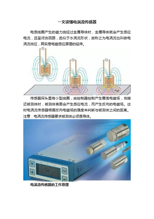
一文读懂电涡流传感器电感线圈产生的磁力线经过金属导体时,金属导体就会产生感应电流,且呈闭合回路,类似于水涡流形状,故称之为电涡流也叫做电涡流效应,其实是电磁感应原理的延伸。
传感器探头里有小型线圈,由控制器控制产生震荡电磁场,当接近被测体时,被测体表面会产生感应电流,而产生反向的电磁场。
这时电涡流传感器根据反向电磁场的强度来判断与被测体之间的距离。
注意:电涡流传感器要求被测体必须是导体。
电涡流传感器的工作原理当接通传感器系统电源时,在前置器内会产生一个高频信号,该信号通过电缆送到探头的头部,在头部周围产生交变磁场H1。
如果在磁场H1的范围没有金属导体接近,则发射到这一范围内的能量都会被释放;反之,如果有金属导体接近探头头部,则交变磁场H1将在导体的表面产生电涡流场,该电涡流场也会产生一个方向与H1相反的交变磁场H2。
由于H2的反作用,就会改变探头头部线圈高频电流的幅度和相位,即改变了线圈的有效阻抗。
这种变化与电涡流效应有关,也与静磁学效应有关(与金属导体的电导率、磁导率、几何形状、线圈几何参数、激励电流频率以及线圈到金属导体的距离参数有关)。
假定金属导体是均质的,其性能是线形和各向同性的,则线圈——金属导体系统的磁导率u、电导率σ、尺寸因子r、线圈与金属导体距离δ线圈激励电流I和频率ω等参数来描述。
因此线圈的阻抗可用函数Z=F(u,σ,r,δ,I,ω)来表示。
如果控制u,σ,r,I,ω恒定不变,那么阻抗Z就成为距离的单值函数,由麦克斯韦尔公式,可以求得此函数为一非线形函数,其曲线为“S”型曲线,在一定范围内可以近似为一线形函数。
通过前置器电子线路的处理,将线圈阻抗Z的变化,即头部体线圈与金属导体的距离δ的变化转化成电压或电流的变化。
输出信号的大小随探头到被测体表面之间的间距而变化,电涡流传感器就是根据这一原理实现对金属物体的位移、振动等参数的测量。
一般来说,传感器线圈的阻抗、电感和品质因数的变化与导体的几何形状、导电率和磁导率有关。
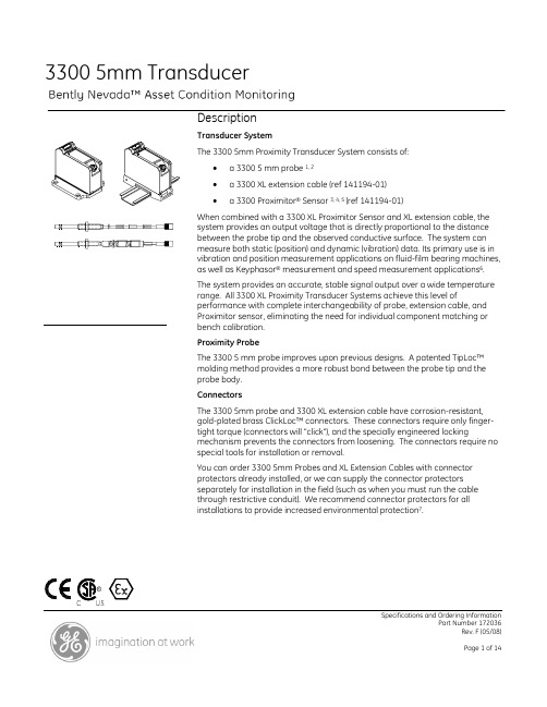
bently 3300 XL 5mm 电涡流传感器系统
3300 5mm TransducerSpecifications and Ordering InformationPart Number 172036Rev. F (05/08)DescriptionTransducer SystemThe 3300 5mm Proximity Transducer System consists of:• a 3300 5 mm probe 1, 2• a 3300 XL extension cable (ref 141194-01) •a 3300 Proximitor ® Sensor 3, 4, 5 (ref 141194-01)When combined with a 3300 XL Proximitor Sensor and XL extension cable, the system provides an output voltage that is directly proportional to the distance between the probe tip and the observed conductive surface. The system can measure both static (position) and dynamic (vibration) data. Its primary use is in vibration and position measurement applications on fluid-film bearing machines, as well as Keyphasor ® measurement and speed measurement applications 6. The system provides an accurate, stable signal output over a wide temperature range. All 3300 XL Proximity Transducer Systems achieve this level ofperformance with complete interchangeability of probe, extension cable, and Proximitor sensor, eliminating the need for individual component matching or bench calibration. Proximity ProbeThe 3300 5 mm probe improves upon previous designs. A patented TipLoc™ molding method provides a more robust bond between the probe tip and the probe body. ConnectorsThe 3300 5mm probe and 3300 XL extension cable have corrosion-resistant, gold-plated brass ClickLoc™ connectors. These connectors require only finger-tight torque (connectors will "click"), and the specially engineered lockingmechanism prevents the connectors from loosening. The connectors require no special tools for installation or removal.You can order 3300 5mm Probes and XL Extension Cables with connector protectors already installed, or we can supply the connector protectors separately for installation in the field (such as when you must run the cable through restrictive conduit). We recommend connector protectors for all installations to provide increased environmental protection 7.Specifications and Ordering InformationPart Number 172036Rev. F (05/08)Notes:1.A 5mm probe uses smaller physical packaging and provides the same linear range as a 3300 XL 8mm probe (ref 141194-01). The 5mm probe does not, however, reduce thesideview clearances or tip-to-tip spacing requirements as compared to an XL 8 mm probe. IYou should use the 5mm probe when physical (not electrical) constraints preclude the use of an 8mm probe, such as mounting between thrust bearing pads or other constrained spaces. When your application requires narrow sideview probes, use the 3300 XL NSv™ probe and extension cable with the 3300 XL NSv Proximitor Sensor (refer to Specifications and Ordering Information p/n 147385-01).2.XL 8 mm probes provide a thicker encapsulation of the probe coil in the molded PPSplastic probe tip to produce a more rugged probe. The larger diameter of the probe body also provides a stronger, more robust case. We recommend the use of XL 8mm probes when possible to provide optimal robustness against physical abuse.3.A 3300 XL Proximitor Sensor is available and provides many improvements over the non-XL version. The XL sensor is electrically and mechanically interchangeable with the non-XL version. Although the packaging of the 3300 XL Proximitor Sensor differs from its predecessor, its design allows you to usea 4-hole mounting base to fit it t in the same 4-hole mounting pattern and to fit within the same mounting space specifications (when the application observes the minimum permissible cable bend radius). Consult Specifications and Ordering Information (p/n 141194-01) or our sales and service professional for more information.4. Us of XL components with 3300 5mm Probes will limit system performance to the specifications for the non-XL 3300 system.5. The factory supplies Proximitor Sensors that are calibrated by default to AISI 4140 steel. Calibration to other target materials is available upon request.6.If you are considering using this transducer system for tachometer or over-speedmeasurements, consult /bently for the application note regarding the use of eddy current proximity probes for over speed protection.7. We provide silicone tape i with each 3300 XL extension cable. You can use this tape instead of connector protectors. We do not recommend silicone tape in applications which will expose the probe-to-extension cable connection to turbine oil.SpecificationsUnless otherwise noted, the following specifications are for a proximity transducer system between +18 °C and +27 °C (+64 °F to +80 °F) with a -24 Vdc power supply, a 10 kΩ load, an AISI 4140 steel target, and a probe gapped at 1.27 mm (50 mils). ElectricalXL ProximitorSensor InputAccepts one noncontacting 33005 mm Proximity Probe and XLExtension Cable.PowerRequires -17.5 Vdc to -26 Vdc at12 mA maximum consumption.Operation at a more positivevoltage than -23.5 Vdc can resultin reduced linear range.SupplySensitivityLess than 2 mV change in outputvoltage per volt change in inputvoltage.Outputresistance50 ΩTable 1: Probe DC ResistanceProbe Length (m)Resistance from the Center Conductor to the Outer Conductor(Ω)0.5 7.45± 0.501.0 7.59 ± 0.501.5 7.73± 0.502.0 7.88 ± 0.505.0 8.73± 0.709.0 9.87 ± 0.90Table 2: Extension Cable DC Resistance Length ofExtensionCableResistance fromCenter Conductor toCenter Conductor(R CORE) (Ω)Resistance fromOuter Conductor toOuter Conductor(R JACKET) (Ω)3.0 0.66± 0.10 0.20 ± 0.043.5 0.77 ± 0.12 0.23 ± 0.054.0 0.88± 0.13 0.26 ± 0.054.5 0.99 ± 0.15 0.30 ± 0.067.0 1.54± 0.23 0.46 ± 0.097.5 1.65 ± 0.25 0.49 ± 0.108.0 1.76± 0.26 0.53 ± 0.118.5 1.87 ± 0.28 0.56 ± 0.11Note:Outer conductor refers to the shielded conductor that is attached to the connector, not the armor braid. Extension cablecapacitance69.9 pF/m (21.3 pF/ft) typical. Field WiringRecommend using 3-conductorshielded triad cable 0.2mm to1.5mm (16 AWG to 24 AWG). 305metres (1,000 feet) maximumlength between 3300 XL ProximityTransducer and monitor. ConsultPerformance Specification155687 for signal rolloff at highfrequencies when using longerfield wiring lengths or externalsafety barriers located somedistance from the monitoringsystem.Linear Range2 mm (80 mils). Linear rangebegins at approximately 0.25 mm(10 mils) from target and is from0.25 to 2.3 mm (10 to 90 mils). RecommendedGap Setting1.27 mm (50 mils).Specifications and Ordering InformationIncrementalScale Factor7.87 V/mm (200 mV/mil) ±6.5%typical, includinginterchangeability error whenmeasured in increments of 0.25mm (10 mils) over the linearrange.Deviation frombest fit straightline (DSL)Less than ±0.038 mm (±1.5 mil)typical deviation from best fitstraight line.ProbeTemperatureStability(typical)Over probe temperature range of-35 °C to +177 °C (-31 °F to +350°F), the incremental scale factorremains within ±10% of 7.87V/mm (200 mV/mil) and thedeviation from the best fit straightline remains within ±0.076 mm(±3 mils).FrequencyResponse0 to 10 kHz: +0, -3 dB, with up to305 metres (1000 feet) of fieldwiring.MinimumTarget Size15.2 mm (0.6 in) diameter(flat target).Shaft DiameterMinimum50.8 mm (2 in)Recommendedminimum76.2 mm (3 in)When gapped at the center of thelinear range, the interactionbetween 2 separate transducersystems (cross-talk) will be lessthan 50 mV on shaft diameters ofat least 50 mm (2 in) or greater.Care should be taken to maintainminimum separation oftransducer tips, generally at least40 mm (1.6 in) for axial positionmeasurements or 38 mm (1.5 in)for radial vibration measurementsto limit cross-talk to 50 mV or less.Radial vibration or positionmeasurements on shaftdiameters smaller than 76.2 mm(3 in) will generally result in achange in scale factor. ConsultPerformance Specification155687 for additional information. Effects of 60 HzMagnetic FieldsUp to 300 GaussSee Table 3.Table 3: Output Voltage in Mil (pk-pk)/Gauss (5-metreSystem)GapXLProximitorSensorProbeXL Ext.Cable10 mil 0.0119 0.0004 0.000450 mil 0.0131 0.0014 0.001490 mil 0.0133 0.0045 0.0045 ElectricalCertificationComplies with the European CEmark.Hazardous Area ApprovalsMultiple approvals for hazardous areas certified by Canadian Standards Association (CSA/NRTL/C) in North America and by Baseefa (2001) in Europe. North AmericaEx ia IIC T4/T5 for Class I Zone 0 orClass 1 Division 1; Groups A, B, C,and D, when installed withintrinsically safe zener barriersper drawing 141092, or wheninstalled with galvanic isolators.Certificate number 1109248(LR26744-222)Specifications and Ordering InformationEx nA IIC T4/T5 for Class I Zone 2 or Class 1 Division 2, Groups A, B, C, and D when installed without barriers per drawing 140979 Specifications and Ordering InformationT5 @ Ta = -35 °C to 85 °C. T4 @ Ta = -51 °C to +100 °C Certificate number 1109248(LR 26744-222)EuropeII 1 G EEx ia IIC T4/T5. EC certificate numberBAS99ATEX1101, when installed per drawing 141092.II 3 G EEx nAII T4/T5. EC certificate numberBAS99ATEX3100U, when installed per drawing 140979 T5 @ Ta= -35 °C to +85 °C T4 @ Ta= -51 °C to +100 °CIEC Ex 3300 XL Proximitor Sensor, iaIECEx BAS04.0055XEx ia IIC T4 / T5 (-51 ºC ≤ Ta ≤ +100 ºC / -35 ºC ≤ Ta ≤ +85 ºC) Terminal Block Connections Ui= -28V Ci = 0 Ii= 140mA Li =10µHPi= 0.84WCoaxial Connection Ui = -28V Ci= 5.7nF Ii = 140mA Li = 0.85mHPi = 0.84W Load ParametersThe capacitance and either the inductance or the inductance to resistance (L/R) ratio of the load connected to the probe coaxial terminal, must not exceed the values in Table 4,Table 4: Maximum Terminal LoadsGroupCapacitance(µF)Inductance (mH)L/R Ratio (µH/Ω)IIC 0.077 0.99 35 IIB0.6447.41142IIA 2.144 15.6 2953300 XL Proximitor Sensor, nAIECEx BAS04.0057XEx nA II T4 / T5 (-51 ºC ≤ Ta ≤ +100 ºC / -35 ºC ≤ Ta ≤ +85 ºC) The terminals must be provided with a level of protection of at least IP54. Ui = -28V3300 5mm Eddy Current Probe, iaIECEx BAS04.0056 Ex ia IIC Temperature Classification per below. T1: -51 ºC to +232 ºC T2: -51 ºC to +177 ºC T3: -51 ºC to +120 ºC T4: -51 ºC to +80 ºC T5: -51 ºC to +40 ºC Ui = -28V Ci = 1.5nF Ii = 140mA Li = 200µHPi =0.84W3300 5mm Eddy Current Probe, nAIECEx BAS04.0058XEx nA II TemperatureClassification per the temperature classifications above.Must be supplied from a voltage limited source.EEx nA for Zone 2, Group IIC, ECcertificate numberBAS99ATEX3100U. MechanicalProbe TipMaterialPolyphenylene sulfide (PPS). Probe CaseMaterialAISI 303 or 304 stainless steel(SST).Probe Cable75Ω triaxial, fluoroethylenepropylene (FEP) insulated probecable in the following lengths: 0.5,1, 2, 5, or 9 metres (1.6, 3.3, 16.4,or 29.5 feet).System Length5 or 9 metres (16.4 or 29.5 feet)including extension cable. Extension CableMaterial75 Ω triaxial, fluoroethylenepropylene (FEP) insulated. Probe andExtension CableArmorFlexible AISI 302 or 304 SST withFEP outer jacket5mm ProbeTensile Strength222 N (50 lbf) probe case to probelead. 222 N (50 lbf) probe lead toextension cable connectors. ConnectormaterialGold-plated brass or gold-platedberyllium copper. Recommendedcase hole andtap size for 1/4-28 case Drill Size0.213 inHole Size0.218 to 0.222 inHole Depth0.376 to 0.750 inTap Size#3Recommendedcase hole andtap size forM8x1 caseDrill Size7.5mmHole Size7.625 to 7.72 mmHole Depth12 to 24 mmTap SizeM8x1Probe casetorque5.1 N·m (45 in·lb) recommended7.3 N·m (65 in·lb) maximum Connector-to-connectortorqueRecommendedtorqueSee Table 5.Table 5: Recommended TorqueConnector Type Tightening Instructions 2 3300 XL gold "click" typeconnectorsFinger tight1 non-XL stainless steelconnector and 1 3300 XLconnectorFinger tight plus 1/8 turnusing pliersSpecifications and Ordering InformationMaximumtorque0.565 N•m (0.42 ft•lbf) Minimum CableBend Radius25.4 mm (1.0 in).WeightTotal System0.71 kg (1.6 lbm), typical.3300 5mm Probe323 g (11.39 oz).XL ExtensionCable34 g/m (0.4 oz/ft)103 g/m (1.5 oz/ft) (armored)XL ProximitorSensor246 g (8.7 oz) Environmental LimitsProbeTemperatureRange:-35 °C to +177 °C (-31 °F to +351°F)Note: Exposing the probe to temperatures below –34 °C (-30 °F) may cause premature failure of the pressure seal.Extension CableTemperatureRange:-51° C to +177° C (-60° F to +351°F) for standard extension cable.ref 141194-01Probe Pressure:3300 5 mm probes are designedto seal differential pressurebetween the probe tip and case.The probe sealing materialconsists of a fluorocarbon O-ring.We do not pressure test probesprior to shipment. Contact ourcustom design department if yourequire a test of the pressure sealfor your application.Note: It is the responsibility of the customer or user to ensure that all liquids and gases are contained and safelycontrolled should a proximity probe. leak In addition,solutions with high or low pH values may erode the tipassembly of the probe causing media to leak intosurrounding areas. Bently Nevada LLC will not be heldresponsible for any damages resulting from leaking 33005 mm proximity probes. In addition, Bently Nevda LLC willnot replace 3300 5mm proximity probes under the serviceplan due to probe leakage.Patents:One or more components orprocedures described in thefollowing patents apply to thisproduct: 5,016,343; 5,126,664;5,351,388; and 5,685,884.Ordering Information3300 5 mm Proximity Probes330171 3300 5 mm Probe, 1/4-28 UNF thread, without armor330172 3300 5 mm Probe, 1/4-28 UNF thread, with armor Part Number-AXX-BXX-CXX-DXX-EXXA:Unthreaded Length OptionNote: Unthreaded length must be at least 0.8 in less than the case length.Order in increments of 0.1inLength configurations:Maximum unthreaded length:8 8 = 8.8 inMinimum unthreaded length:0 0 = 0.0 inExample: 0 4 = 0.4 inB: Overall Case Length OptionOrder in increments of 0.1 inThreaded length configurations:Maximum case length:9 6 = 9.6 inMin. case length:0 8 = 0.8 inExample: 2 4 = 2.4 inC: Total Length Option0 5 0.5 metre (1.6 feet)Specifications and Ordering Information1 0 1.0 metre (3.3 feet)2 0 2.0 metres (6.6 feet)5 0 5.0 metres (16.4 feet) 19 0 9.0 metres (29.5 feet)D: Connector Option0 1 Miniature coaxial ClickLocconnector with connectorprotector, standard cable0 2Miniature coaxial ClickLocconnector, standard cable E:Agency Approval Option0 0 Notrequired0 5 MultipleApprovals 3300 5mm Proximity Probes, Metric330173 3300 5 mm Probe, M8 x 1 thread, without armor 330174 3300 5 mm Probe, M8 x 1 thread, with armor Part Number-AXX-BXX-CXX-DXX-EXXA:Unthreaded Length OptionNote: Unthreaded length must be at least 20 mm less than the case length.Order in increments of 10 mm.Length configuration:Max. unthreaded length: 2 3 = 230mmMin. unthreaded length: 0 0 = 0.0mmExample: 0 6 = 60 mm.B: Overall Case Length OptionOrder in increments of 10 mm.Metric thread configurations:Maximum length:2 5 = 250 mmMinimum length:0 2 = 20 mmExamples: 0 6 = 60 mm.C:Total Length Option0 50.5 metre (1.6 feet)1 0 1.0 metre (3.3 feet)2 0 2.0 metres (6.6 feet)5 0 5.0 metres (16.4 feet) 19 0 9.0 metres (29.5 feet)Probe AccessoriesAluminum probe mounting bracketThe aluminum probe threaded mounting bracket is the standard mounting bracket for most 3300 5 mm probe installations. The -02 option is supplied with 2 10-24 UNC-2A mounting screws. The -03 option is supplied with 2 M5 x 0.8-6g mounting screws. The mounting screws have pre-drilled holes for safety wire. 137492 -AXXA: Thread size0 2 1/4-280 3 M8 x 1Phenolic Probe Mounting BracketThe phenolic mounting bracket is recommended if additional electric isolation from the mounting location is required (as in some generator and electrical motor bearing locations). The -02 option is supplied with 2 10-24 UNC-2A mounting screws. The -03 option is supplied with 2 M5 x 0.8-6g mounting screws. The mounting screws have pre-drilled holes for safety wire.27474 -AXXA: Thread size0 2 1/4-280 3M8 x 175Ω ClickLoc Connector Kit330153-AA75Ω ClickLoc Connector Kit for 3300 series probes and extension cables. Each kit contains 1 color-coded sleeve per connector.A: Kit Type0 2 1 ClickLoc male connector for3300 XL 5mm and 8mmextension cable.0 3 1 ClickLoc female connectorfor 3300 XL 5mm and 8mmextension cable.0 4 1 ClickLoc male connector for3300 5mm probe. Accessories02120015Bulk field wire. 1.0 mm2 (18AWG), 3-conductor, twisted,shielded cable for connectionsbetween Proximitor Sensor andmonitor.03200006Silicone self-fusing tape.9.1-metre (10-yard) roll of siliconetape to protect connectors. It iseasy to install and providesexcellent electrical isolation andprotection from the environment.Specifications and Ordering InformationIt is not recommended for useinside the casing of the machine. 40113-03Connector Protector Kit.Connector Protector Kit for 33005mm probes, including connectorprotectors and installation tools. 136536-01Connector Protector Adapter.Makes connector protector kitspurchased prior to 1998compatible with ClickLocextension cable connectors. 40180-03Connector Protectors. Packagecontaining 10 pairs of 75ΩCoaxial Connector Protectors. 0383941075Ω Triaxial/95 ohm CoaxialMale Connector Protector.Placed onto the extension cable;attaches to the female connectorprotector on the 5 mm probe toprovide environmental protectionof connectors.0380000175Ω Coaxial Female ConnectorProtector. Placed onto 3300 5mmprobe leads; attaches to the maleconnector protector on theextension cable to provideenvironmental protection ofconnectors.163356Connector Crimp Tool Kit.Includes 1 set of multi-connectorinserts and connector installationinstructions. Compatible onlywith 330153 connector kits orwith probes shipped in 2003 orlater with ClickLoc connectorsuninstalled. Supplied withcarrying case.Specifications and Ordering InformationGraphsFigure 1 - Typical 3300 5 mm probe and 1 metre of cable at high and low temperatures (XL Proximitor Sensor and XL extensioncable are at 25°C)Specifications and Ordering InformationFigure 2 - 3300 5 metre XL Proximitor Sensor at high temperatures (3300 5mm probe and XL extension cable at 25° C) Dimensional diagramsSpecifications and Ordering Information1. Probe tip, 5.2 mm [0,21 in] diameter2. 11.1 mm [7/16 in] for 1/4-28 threads, 13.0 mm [0.51 in] for M8 thread. See Note 3.3. Case thread4. 5.6 [7/32] wrench flats for 1/4-28 threads, 7.0 [0.28] for M8 threads5. 75Ω cable, 2.8 mm [0.11 in] maximum outside diameter, 7.6 mm [0.3 in] outside diameter of armor, 9.0 mm [0.35 in] maximumdiameter of armor ferrule.6. Miniature male coaxial connector,7.23 mm [0.285 in] maximum outside diameter “D”7. 3.2 [0.13 in]8. Unthreaded length “A”9. Case length “B”10. 6.0 mm [0.235 in] maximum11. Total length “C”, =30%, -0%. See Note 8.Figure 3 - 3300 5 mm Proximity Probes, Standard Mount3330171, 1/4-28 UNF-2A, without armor7330172, 1/4-28 UNF-2A, with armor6330173, M8X1 thread, without armor7330174, M8X1 thread, with armor6Specifications and Ordering Information1. 12 mm [0.40 in] maximumd diameter2. 36.3 mm [1.43 in] maximum3. 51.1 mm [2.01 in] maximum4. Connector protector (fluorosilicone material)Figure 4 - Installed Connector Protectors1. 7.2 mm [0.25 in] maximum diameter2. Miniature male coaxial connector3. FEP or PFA coated armor. Armor length is 300 mm [11.8 in] less than cable length. See Note 6.4. 75Ω cable, 3.7 mm [0.15 in] maximum outside diameter, 3.9 mm [0.16 in] maximum diameter for FluidLoc® cable, 7.6 mm [0.30in] maximum outside diameter or armor, 9.0 mm [0.35 in] maximum diameter of armor ferrule.5. Stainless steel ferrules, 8.4 mm [0.33] diameter6. Miniature female coaxial connector7. Cable length, +20%, -0%Figure 5 - 3300 XL Extension Cable330130, 3300 XL Extension Cable (FEP armor and insulation)Notes:1. All dimensions are in millimetres (inches) unless otherwise noted.3. Standard mount 5 mm probes supplied with 13 mm or 7/16-in lock nut.5. Letters inside quotation marks refer to probe ordering options.6. Stainless steel armor is supplied with FEP outer jacket for standard probes, PFA outer jacket for ETR probes.Specifications and Ordering Information7. FEP jacket is standard non-armored portion of the cable for standard probes, PFA jacket on non-armored portion for ETR probes.8. Probes ordered with 5 or 9 metre integral cables have a length tolerance of +20%, -0%.9. Five metre probes are designed for use with the five metre Proximitor Sensor only.Add notes for missing numbers, even if it is something like “Deleted” or “Note removed”, or renumber the notes in the document.Bently Nevada, Proximitor, Keyphasor, TipLoc, and ClickLoc are trademarks of General Electric Company.Copyright 2005. Bently Nevada LLC.1631 Bently Parkway South, Minden, Nevada USA 89423Phone: 775.782.3611 Fax: 775.215.2873/bentlyAll rights reserved.Specifications and Ordering Information。
本特利传感器介绍

基于安装
传感器安装位置 • 测轴位移的传感器应尽可能靠近推力 轴承 • 测径向振动的传感器
– 安装在同一轴向平面内 – 两个传感器正交分布
考虑安装空间的限制
保证测量精度
加速度传感器 • 安 装 点 清 理 油 漆、 异 物 • 安装点保证一定的平面度 键相位传感器 • 每 个 转 速 或 旋 转 方 向 不 同 的 轴, 都 应 安装一个键相位传感器
or
= 7.87 mV/um
组成元件不匹配的影响
24 22 20
SHORT
18
OUTPUT (-Vdc) (
16 14 12 10 8 6 4 2 0 0 10 20 30 40
CORRECT
LONG
50
60
70
80
90
100 110 120 130 140
PROBE GAP (mils)
输入电压的影响
Velomitor 的 频 率 响 应
Velomitor 的 特 点
优点 • 安装简便 • 良好的中频响应 • 长时间使用可靠性好 • 使用温度范围宽
Velomitor 的 特 点
缺点 • 校验需要振动台 • 需要连续供电 • 低频响应差
加速度传感器 (Accelerometer)
加速度传感器的结构
<100mil
线性范围
RF SIGNAL
趋近传感器系统 - Eddie Current
导电材料
RF 信 号
电涡流
趋近传感器系统– Gap Signal 近传感器系统
RF SIGNAL
0
RF SIGNAL
0
RF SIGNAL
0
趋近传感器系统– Prox Output 近传感器系统
本特利电涡流传感器的安装及常见故障处理
(hn u hn hmi l o , t.S a n i hn 13 9,hn ) Seh aS emuC e c . d ,h ax emu7 9 1 C ia aC L S
关键 词 : 头 ; 用 ; 探 应 系统 ; 方法
中图分 类号 :P 1 . 3 T 2 24
文 献标 志码 : B
文章编 号 :0 0— 6 2 2 1 ) 4— 0 7— 3 10 0 8 ( 0 1 0 0 8 0
Be ly e d ur e e s r i sal to n t o l - h o i r c s i nte d y c r nts n o n t l i n a d r ub e s o tng p o e sng a
l 本 特 利 监 测 系统 结 构
离心压缩机组的监测系统主要 由电涡流传感器
探 头 、 伸 电 缆 、 置 器 以 及 30 延 前 5 0检 测 模 块 组 成 。 探 头安装 于现场设 备 , 检测 轴 承 的振 动 和位移 等量 ;
厂安装 前 , 已由压 缩 机厂 家完成 , 表维 护人员 在 日 仪
常检修 中, 一般只需进行④ 、 、 ⑤ ⑥项工作 , 若前 3 项
必 须重新 进 行确定 , 要 与厂 家沟通 , 需 由厂家派 员 和 仪 表维 护人 员共 同完 成 。
2 1 探 头 的安装 间 隙 .
延伸电缆用来连接和延伸探头与前置器 , 传输探头 检测 到 的信 号 ; 置 器 接 收 由探 头 和 延 伸 电缆传 输 前
本特利内华达3300 XL 8mm涡流传感器手册

(位置与方向-轴向位移探头)。美国石油协会出版发行,1220 L Street NW,
Washington DC,20005,USA
参考文件(133055-01)
本特利内华达术语表
iii
3300 XL 8 毫米和 3300 5 毫米涡流传感器系统安装手册
产品处置声明
使用本产品或产品达到使用寿命期限后的非欧盟成员国家客户和第三方是恰当处置产 品废弃物的唯一责任人。任何个人、公司、组织或者机构在产品使用过程中不得违反 美国州法律、美国联邦法律、当地国家法律或国际法律对废弃物的规定。本特利内华 达公司不承担产品使用过程中或者达到寿命期限后废弃物处理的责任。
安装传感器
•
涡流探头和相关附件的最佳实践经验:电涡流传感器的安装与应用
•
本特利内华达旋转机械信息系统接地导则
•
危险区域内电气设备的安装
•
电涡流探头用于超速保护时的注意事项
•
“小故障”:消除电气跳动的轴抛光等校正的定义与方法
传感器安装附件
•
31000/32000 涡流探头防护箱手册(部件号 124200-01)
vi
目录
1. 系统综述 .......................................................................................................... 1
1.1 传感器系统 .......................................................................................................................................... 1 1.2 前置器 .................................................................................................................................................... 1 1.3 涡流探头和延长电缆 ...................................................................................................................... 2 1.4 接头 ......................................................................................................................................................... 2 1.5 扩展的温度范围应用 ...................................................................................................................... 2 1.6 到货检查与系统拆装 ...................................................................................................................... 3 1.7 客户服务 ............................................................................................................................................... 3
本特利轴向位移探头型号

本特利轴向位移探头说明3300 XL 11mm 电涡流传感器系统对于油膜轴承机器非接触式振动和位移测量,3300 XL 11mm电涡流传感器系统可输出3.94 V/mm(100mV/mil)。
11mm的探头端部使这种传感器与我们标准的3300 XL8mm传感器系统相比具有更大的线性区。
它主要应用在要求大线性范围的下列测量:轴向(推力)位移测量蒸汽轮机的斜面差胀测量往复式压缩机活塞杆位移或下降的测量转速计和零转速测量相位参考(键相位)信号330701 3300 XL 11mm探头,1/2-20 UNF螺纹,非铠装330702 3300 XL 11mm探头,1/2-20 UNF螺纹,铠装330707 3300 XL 11mm探头,5/8-18 UNF螺纹,非铠装本特利(Bently Nevada)330707-05-35-10-02-00本特利(Bently Nevada)330707-00-62-10-01-00本特利(Bently Nevada)330707-00-20-10-02-00330708 3300 XL 11mm探头,5/8-18 UNF螺纹,铠装3300 XL 11mm 电涡流探头,公制330703 3300 XL 11mm探头,M14×1.5螺纹,非铠装本特利(Bently Nevada)330703-000-040-50-11-00本特利(Bently Nevada)330703-000-040-10-02-00本特利(Bently Nevada)330703-000-050-10-02-00本特利(Bently Nevada)330703-000-050-50-02-00本特利(Bently Nevada)330703-000-060-10-02-00本特利(Bently Nevada)330703-000-060-90-02-00本特利(Bently Nevada)330703-000-064-90-02-00本特利(Bently Nevada)330703-000-070-10-02-00本特利(Bently Nevada)330703-000-080-10-02-00本特利(Bently Nevada)330703-000-090-10-02-00本特利(Bently Nevada)330703-000-100-10-02-00本特利(Bently Nevada)330703-000-120-10-02-00本特利(Bently Nevada)330703-050-120-10-02-00330704 3300 XL 11mm探头,M14×1.5螺纹,铠装本特利(Bently Nevada)330704-000-100-10-11-00本特利(Bently Nevada)330704-000-040-10-02-00本特利(Bently Nevada)330704-000-050-10-01-05本特利(Bently Nevada)330704-000-050-10-02-00本特利(Bently Nevada)330704-000-060-10-02-00本特利(Bently Nevada)330704-000-060-90-02-00本特利(Bently Nevada)330704-000-080-10-02-00本特利(Bently Nevada)330704-000-080-50-02-00330709 3300 XL 11mm探头,M16×1.5螺纹,非铠装本特利(Bently Nevada)330709-000-030-10-02-00本特利(Bently Nevada)330709-000-040-10-02-00本特利(Bently Nevada)330709-000-040-50-02-05本特利(Bently Nevada)330709-000-050-10-02-00本特利(Bently Nevada)330709-000-060-10-02-00本特利(Bently Nevada)330709-000-060-50-02-00本特利(Bently Nevada)330709-000-060-90-02-00本特利(Bently Nevada)330709-000-070-10-02-00本特利(Bently Nevada)330709-000-080-10-02-00本特利(Bently Nevada)330709-000-120-10-02-00本特利(Bently Nevada)330709-010-070-10-02-00本特利(Bently Nevada)330709-010-130-10-02-00本特利(Bently Nevada)330709-050-120-10-02-00330710 3300 XL 11mm探头,M16×1.5螺纹,铠装本特利(Bently Nevada)330710-000-040-10-11-00本特利(Bently Nevada)330710-000-050-10-02-00本特利(Bently Nevada)330710-000-060-10-02-00本特利(Bently Nevada)330710-050-124-10-02-00本特利(Bently Nevada)330710-050-124-90-02-003300 XL 11mm 反装探头330705-02-18-CXX-DXX-EXX,3/8-24 UNF螺纹本特利(Bently Nevada)330705-02-18-10-02-00本特利(Bently Nevada)330705-02-18-90-02-00本特利(Bently Nevada)330705-02-18-90-02-05330706-005-046-CXX-DXX-EXX,M10×1螺纹本特利(Bently Nevada)330706-005-046-10-02-00本特利(Bently Nevada)330706-005-046-10-02-053300 XL 11mm前置器本特利(Bently Nevada)330780-50-00本特利(Bently Nevada)330780-50-05本特利(Bently Nevada)330780-51-00本特利(Bently Nevada)330780-90-00本特利(Bently Nevada)330780-91-00本特利(Bently Nevada)330780-91-053300 XL 11mm 延伸电缆本特利(Bently Nevada)330730-040-00-00本特利(Bently Nevada)330730-040-01-00本特利(Bently Nevada)330730-040-03-00本特利(Bently Nevada)330730-040-12-00本特利(Bently Nevada)330730-040-13-00本特利(Bently Nevada)330730-080-00-00本特利(Bently Nevada)330730-080-01-00本特利(Bently Nevada)330730-080-02-00本特利(Bently Nevada)330730-080-11-00本特利(Bently Nevada)330730-080-12-00本特利系统主要是对大型旋转设备的振动检测,测量转子和机壳的振动、速度、加速度和位移。
电涡流传感器详解

电涡流传感器详解电涡流传感器详解一、电涡流传感器的基本类型分为高频反射式电涡流传感器和低频透射式电涡流传感器。
激励频率的选择原则为:待测导体的厚度大,应选择较低的激励频率以保证线性度,反之则使用较高激励频率以提高灵敏度。
二、电涡流传感器的典型应用电涡流传感器系统广泛应用于电力、石油、化工、冶金等行业和一些科研单位。
对汽轮机、水轮机、鼓风机、压缩机、空分机、齿轮箱、大型冷却泵等大型旋转机械轴的径向振动、轴向位移、键相器、轴转速、胀差、偏心、以及转子动力学研究和零件尺寸检验等进行在线测量和保护。
胀差测量斜坡式胀差测量补偿式胀差测量双斜面胀差测量振动测量轴位移测量轴心轨迹测量差动测量动力膨胀转子动平径向运动分析转速和相位差测试转速测量表面不平整度测量裂痕测量非导电材料厚度测量金属元件合格检测轴承测量换向片测量1、相对振动测量测量径向振动,可以由它分析轴承的工作状态,还可以看到分析转子的不平衡,不对中等机械故障。
电涡流传感器系统可以提供对于下列关键或是基础机械状态监测所需要的信息:●工业透平,蒸汽/燃气●压缩机,径向/轴向●膨胀机●动力发电透平,蒸汽/燃气/水利●发动马达●发动机●励磁机●齿轮箱●泵●风箱●鼓风机●往复式机械(1)相对振动测量(小型机械)振动测量同样可以用于对一般性的小型机械进行连续监测。
电涡流传感器系统可为如下各种机械故障的早期判别提供重要信息:●轴的同步振动●油膜失稳●转子摩擦●部件松动●轴承套筒松动●压缩机踹振●滚动部件轴承失效●径向预载,内部/外部包括不对中●轴承巴氏合金磨损●轴承间隙过大,径向/轴向●平衡(阻气)活塞●联轴器“锁死”磨损/失效●轴裂纹●轴弯曲●齿轮咬合问题●电动马达空气间隙不匀●叶轮通过现象●透平叶片通道共振(2)偏心测量偏心是在低转速的情况下,电涡流传感器系统可对轴弯曲的程度进行测量,这些弯曲可由下列情况引起:●原有的机械弯曲●临时温升导致的弯曲●重力弯曲●外力造成的弯曲偏心的测量,对于评价旋转机械全面的机械状态,是非常重要的。
美国本特利3300耐高温电涡流传感器系统
C: 硬连线长度 选项:
1 0 1.0 米 (3.3 英尺) 2 0 2.0 米 (6.6 英尺) 5 0 5.0 米 (16.4 英尺)
D: 总长度 选项:
注:延伸电缆包含在电涡流 探头中 9 0 9.0 米 (29.5 英尺)
பைடு நூலகம்
E: 延伸电缆铠装 选项:
0 0 无不锈钢铠装 0 1 不锈钢铠装
F: 批准机构 选项:
50Ω
探头直流阻抗
探头长度(m) 从中心导体到外部导体的阻抗 (RPROBE)(ohms)
1.0
5.06
2.0
5.82
5.0
8.11
延伸电缆直流阻抗:
延伸电 缆长度 (m)
从中心导体到中 心导体的阻抗 (RCORE)(ohms)
4.0
0.88
7.0
1.62
8.0
1.84
从同轴导体到同轴 导体的阻抗
(RJACKET)(ohms)
探头壳体材料:AISI 316L 不锈钢(SST)
探头电缆规格:
1、2 或 5 米长的 AISI 304L 不锈钢硬线电缆
延伸电缆材料: 75Ω三维轴向氟乙烯丙烯 (FEP)绝缘电缆
前置器材料:
环氧粉末涂层铝
系统长度: 包括延伸电缆为 9 米
延伸电缆铠装 (可选):
弹性 AISI302 SST 不锈钢,具有 FEP 外皮
推荐最小轴直径:152mm(6.0inch)
注:对直径小于 76mm(3.0inch)的轴进行测 量通常要求更近的径向振动 或轴向位移传感器间距,这 样有可能使它们的电磁场互 相干扰(串扰),导致读数 错误。为防止串扰,对于复 合轴向位移测量,传感器端 部相距至少 64mm(2.5inch),对于径向 振动测量,传感器端部相距 至少 54mm(2.1inch)。对直 径小于 152mm(6.0inch)的轴 进行径向振动或轴向位移测 量时,通常会由于轴表面圆 度的变化而导致灵敏度发生 改变。更多信息请参阅性能 技术说明 159132。
bently 3300 XL 25mm 电涡流传感器系统
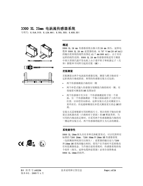
BN 部 件 号 163236 版本 NC,2003 年 1 月
技术说明和订货信息
Page 1 of 26
趋近式探头和延伸电缆
3300 XL 25 mm 探头设计用于最苛刻的蒸汽透 平 DE 环境。它能在高达 200°C(392°F)的温 度下持续运行并保持精度,还可以承受 250°C (482°F)的间歇高温。25 mm 探头前后密 封,并使用 FluidLoc® 电缆(所有标准 25 mm 探头),防止湿气进入探头端部。特殊的 高温 ClickLoc™ 接头也是探头和延伸电缆的 标准配置。每个探头和电缆都带有接头保护 器和一次性接头保护器安装工具,确保接头 不受污染。探头头部上的 ClickLoc™ 接头具 有可拆卸的衬套,帮助在紧密间隙内缠绕电 缆。
最小弯曲半径(有或 没有 sst 铠装): 25.4 mm (1.0 in)
系统重量(典型值)
探头:
230 g (8.1 oz)(最小 长度壳体,1m 探头 头部,无铠装)
330 g (11.6 oz)(最小 长度壳体,1m 探头 头部,铠装)
对于更长的探头壳体, 当长度增加时,重量的增 加为 5.7g/mm (5.1 oz/in)
额定最大值
163 N·m (120 ft·lb)
9.6 N·m (85 in·lb)
10.7 N·m (95 in·lb)
推荐值
68 N·m (50 ft·lb)
7.3 N·m (65 in·lb)
7.3 N·m (65 in·lb)
接头对接头扭矩
推荐扭矩: 手指紧固
最大扭矩:
0.565 N·m (5 in·lb)
线性范围:
12.7mm(500mils) 。线 性范围从距被测靶面约 0.63mm(25mils)处开 始,从 0.63 至 13.33mm (25 至 525mils)(约1.5 至-11.5Vdc)
本特利电涡流传感器工作原理、安装及常见故障总结处理
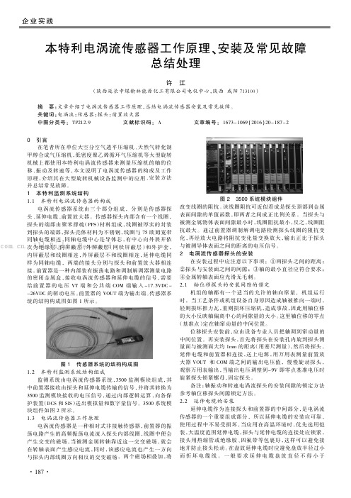
引言在笔者所在单位大空分空气透平压缩机、天然气转化制甲醇合成气压缩机,低密度聚乙烯循环气压缩机等大型旋转机械上都使用本特利电涡流传感器来测量压缩机的轴的位移、振动及转速等,本文说明了电涡流传感器的构成及工作原理,介绍其在大型旋转机械设备监测中的应用、安装方法并总结常见故障。
1本特利监测系统结构1.1本特利电涡流传感器的构成电涡流传感器系统由三个部分组成,分别是传感器探头、延伸电缆、前置放大器。
传感器探头内部含有一个线圈,探头的端部由聚苯撑硫(PPS )材料组成,线圈被厚实的封装到探头的端部,探头壳体材料为不锈钢,线圈与75欧姆宽带同轴电缆相连,同轴电缆中心是导体芯,有中心向外展开依次为绝缘层、内屏蔽层、外屏蔽层(网状屏蔽层)和外护套,内屏蔽层和线圈相连,外屏蔽层不和线圈相连,延伸电缆同样为同轴电缆,两端的接头分别与探头和前置放大器相连接。
前置器是一种内部装有振荡电路和调制解调器测量电路的密闭金属盒,接收电涡流传感器和延伸电缆的信号,需要给前置器的电压VT 端和公共端COM 端输入-17.5VDC ~-26VDC 的驱动电压。
前置器的VOUT 端为输出端。
传感器系统的结构构成图如图1所示。
图1传感器系统的结构构成图1.2本特利监测系统结构组成监测系统由电涡流传感器系统,3500监测模块组成,其中前置器接收由探头和延伸电缆传输的信号,并将其转换为3500监测模块接收的电压信号,通过内部逻辑运算,向各保护装置(DCS 和SIS )送出模拟量和数字量信号。
3500系统模块组件如图2所示。
1.3电涡流传感器工作原理电涡流传感器是一种相对式非接触传感器,前置器的振荡电路产生的高频振荡电流流入探头内部线圈,线圈中便会产生交变的磁场,当被测金属转轴靠近这一交变磁场,就会在转轴表面产生感应电流,同时,该感应电流也产生一方向与探头内部线圈方向相反的交变磁场,两个磁场相叠加,将改变线圈的阻抗。
该线圈阻抗可近似看成是探头顶部到金属表面间隙的单值函数,即两者之间成正比例关系。
本特利传感器简介

2具体安装
键相和偏心安装:固定支架固定牢固后,慢慢安装固定两个探头的同时 用万用表测量前置器反馈电压,两个反馈电压设计均为-11.0V。
2、速和零转速
具体安装
转速和零转速测量示意图
转速探头外观检查
测量转速探头到齿面的间 隙(1mm左右)
3 、轴向位移
1)、工作原理:大轴在运行中,由于各种因素,诸如载荷、温度等的变化会使轴在轴向 有所移动。这样转子和定子之间有可能发生动静磨擦,所以需用传感器测量转子相对于 定子轴向位置的变化,如下图所示,两个涡流探头测量转子的轴向变化,输出探头与被 测法兰的间隙成正比的直流电压值,板件接受此电压值后,经过计算处理,显示出位移 值。
高压差胀:量程-3--+9mm报警:-2.5 or 7.5毫米, 延时: 3s, 危险: -3 or 8毫米 延时: 1s. 闭锁安 装方向:趋近为正 安装电压:-9V
低压胀差:量程-2--+10mm报警:-2 or 6.5毫米, 延时: 3s, 危险: -2or 7.5毫米 延时: 1s. 闭锁 安装方向:远离为正 安装电压:-3.74V
90—代表探头及电缆(内部及延伸)整 个系统的总长度为9米; 00—代表不需要在危险区域使用
2、电涡流位移传感器工作原理
注: 1000mil=1英寸 1英寸=25.4mm
原理:当探头顶部的线圈加上高频电流并与一导体表面靠近时, 1丝=0.01mm
由于线圈磁力线的作用,使导电物体表面产生电涡流,从而使 线圈的电感量减小。线圈特性的这个变化被转换成为直流电压 信号输出。 当探头与被测对象之间的间隙距离最小时,振幅最小,电涡流 最大;当探头与被测对象间的间隙距离最大时,振幅最大,电 涡流最小。
本特利传感器简介
电涡流传感器原理讲解ppt课件

返回
严格执行突发事件上报制度、校外活 动报批 制度等 相关规 章制度 。做到 及时发 现、制 止、汇 报并处 理各类 违纪行 为或突 发事件 。
6.3 电容式位移检测方法
平行极板电容器的电容为 (6-4)
式中,C为电容量;ε为极板介质的介电常数;S 为极板面积;d为极板J间距离。在介电常数ε和S 一定的情况下,极板距离与电容量成反比。因此 可将一块极板固定,另一块极板与被测物体相连, 那么被测物体的位移使得极板距离变化,
严格执行突发事件上报制度、校外活 动报批 制度等 相关规 章制度 。做到 及时发 现、制 止、汇 报并处 理各类 违纪行 为或突 发事件 。
轴向位移时,传感器的输出电压与轴向位移成比例。 当位移值超过规定的允许值时,传感器的输出电 压可控制报警电路发出报警信号。
本章重点介绍广泛应用于大型转动设备(如汽轮 机、压缩机等)轴位移、轴振动测量仪表—“电涡 流式传感器”
6.2.2 高频反射式电涡流传感器
这种传感器的结构很简单,主要由一个固定在 框架上的扁平线圈组成。线圈可以粘贴在框架的 端部,也可以绕在框架端部的槽内。图6-4为某 种型号的高频反射式电涡流传感器。
图6-4 高频反射式电涡流传感器
严格执行突发事件上报制度、校外活 动报批 制度等 相关规 章制度 。做到 及时发 现、制 止、汇 报并处 理各类 违纪行 为或突 发事件 。
严格执行突发事件上报制度、校外活 动报批 制度等 相关规 章制度 。做到 及时发 现、制 止、汇 报并处 理各类 违纪行 为或突 发事件 。
6.2.1 原理与特性
如下图6-2所示,一个扁平线圈置于金属导体附 近,当线圈中通有交变电流I1时,线圈周围就产 生一个交变磁场H1。置于这一磁场中的金属导体 就产生电涡流I2,电涡流也将产生一个新磁场H2, H2与H1方向相反,因而抵消部分原磁场,使通电 线圈的有效阻抗发生变化。
美国本特利3300 XL 8MM 电涡流传感器系统
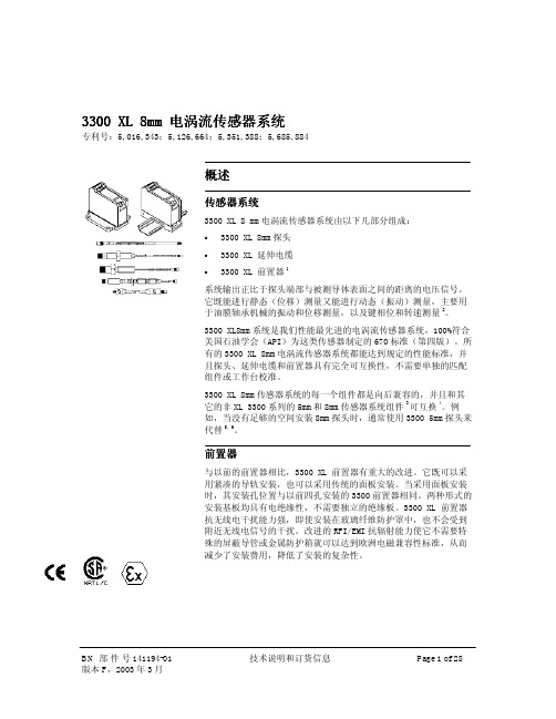
3300 XL 8mm 传感器系统的每一个组件都是向后兼容的,并且和其 它的非 XL 3300 系列的 5mm 和 8mm 传感器系统组件 3 可互换 4。例 如,当没有足够的空间安装 8mm 探头时,通常使用 3300 5mm 探头来 代替 。 5,6
3300 XL 8mm 探头和延伸电缆在订货时可选择 已安装接头保护器,也可以选择在现场安装 (如电缆必须布放在约束导管中)。潮湿环 境中为接头,推荐在所有的安装中都选用接 头保护器,提供环境保护 7。
大温度范围应用
当探头引线或延伸电缆在应用中可能超过 177ºC(350ºF)时,可以采用大温度范围 (ETR)探头和延伸电缆。大温度范围探头的 探头引线和接头的温度范围可达 260ºC (500ºF)。ETR 探头和延伸电缆与标准温度 范围的探头和电缆兼容。例如,可以将 ETR 探头和 330130 延伸电缆一起使用。
技术规格
在没有另外注明时,以下关于 3300 XL8 mm 前置器、延伸电缆和探头的技术规格是在下 列条件下得到的:温度+18°C~+27°C (+64°F~+80°F°),-24Vdc 电源供电, 10KΩ负载,AISI4140 钢被测靶面,探头间隙 为 1.27mm (50mils)。 技术特性适用于完全 由 3300 XL 8mm 部件组成的系统。其精度和 可互换性指标不适用于未经本特利内华达 AISI 4140 钢靶面校准的传感器系统。
机组仪表-本特利探头(传感器的静态校验)

(3)将-24VDC送到前置放大器的电源端和公共端,调节TK3-2E校验仪上的螺 旋千分尺,使示值对准0 mm处,然后将千分尺的示值增加到0.25 mm,记录 数字电压表的电压值(此值为前置器输出电压)。以每次0.25 mm的数值增加间 隙,直到示值为2.5mm为止,并记录每一次的输出电压值。(校验点不少于10 点)。
前置器检测电路检测探头线圈的感抗变化。再经放大电路 将感抗变化量变换放大成相应电压变化信号输出。经监测 仪进行信号转换并显示,转换成4~20mA,1~5V的标准信号送 入DCS或PLC中,在测量中,前置器放大输出的直流电压信 号用做机械位移的测量,交流电压信号用做振动的测量。
机械转速主要是测转子的齿轮或孔眼,经过传感器产生脉 冲或方波,并通过频率信号输出。在现场实际应用的传感 器原理不同。一般有电涡流传感器、磁电式传感器、光电 式传感器等
二、工作原理 机器的振动、位移总是伴随着机器的运转,即使是机器在
最佳的运动状态,由于很微小的缺陷,也将产生某些振动 。在工作中我们常用的振动位移监测仪是由电涡流传感器 、前置器、延伸电缆、监测仪转换器组成,其构成原理如 图所示。探头线圈监测仪
探头线圈接受前置器振荡电路来的高频电流,在其周围产 生高频磁场,该磁场穿过靠近它的转轴金属表面,在其中 产生一个电涡流,该电涡流产生的磁场方向和线圈磁场方 向相反,改变了原线圈的感抗,该感抗的变化随探头顶部 金属表面的间隙变化而变化。
(2)延伸电缆完整、无短路、无开路、接头无氧化锈蚀 ,保护层无破损。
(3)前置器完整无损,安装盒无脱漆、变形和密封不良 现象,前置器与安装盒之间需有良好的绝缘层。
(4)信号电缆屏蔽层接地良好,用500V兆欧表检查信号 线间及对地绝缘电阻应大于5 MΩ。并要求单点接地。
本特利探头说明书
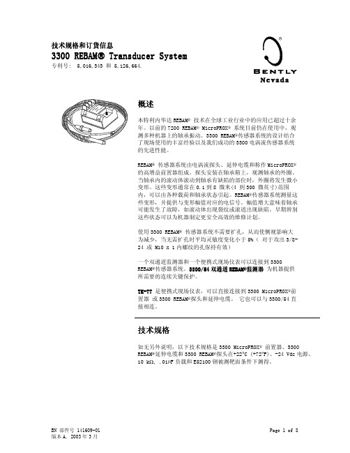
BN 部件号 141609-01 版本 A, 2003 年 3 月
Page 1 of 8
电气特性
MicroPROX® 前置器输入:
接收一个 3300 REBAM®电涡流 探头和延伸电缆的输入
电源:
无安全栅时要求-17.5 Vdc 到 -26 Vdc,最大消耗 12 mA,有 安全栅时要求-23 Vdc 到 -26 Vdc 。在比-23.5 Vdc 更向正 向偏离的电压下使用将导致 线性范围降低
200 µm (8 mils)。线性范围 在距离被测靶面约 230 µm (9 mils)处开始,从 230 到 430 µm (9 到 17 mils)
增量灵敏度
40 V/mm (1 V/mil) 系统:
40 V/mm (1 V/mil) ± 8.3% ,包括互换性误差,当 在 400 µm (16 mil)线性范围 内以 25 µm (1 mil)的增量测 量时
偏离小于 9.1 µm (0.36 mil),包括在中等间隙(-9 V) 时的互换性误差
80 V/mm (2 V/mil) 系统:
偏离小于 16 µm (0.63 mil) ,包括在中等间隙(-9 V)时的互换性误差
BN 部件号 141609-01 版本 A, 2003 年 3 月
Page 2 of 8
B: 壳体总长度 选项
订货时以 0.1in 递 螺纹长度组态: 最大壳体长度: 9.6 in 最小壳体长度: 1.0 in 例如: 2 4 = 2.4 in
C: 总长度选项 1 0 1.0 米 (39 in)
D: 接头选项
0 0 不提供接头 0 2 微型同轴阳接头
Page 4 of 8
E: 批准机构选项 0 0 05
本特利产品说明
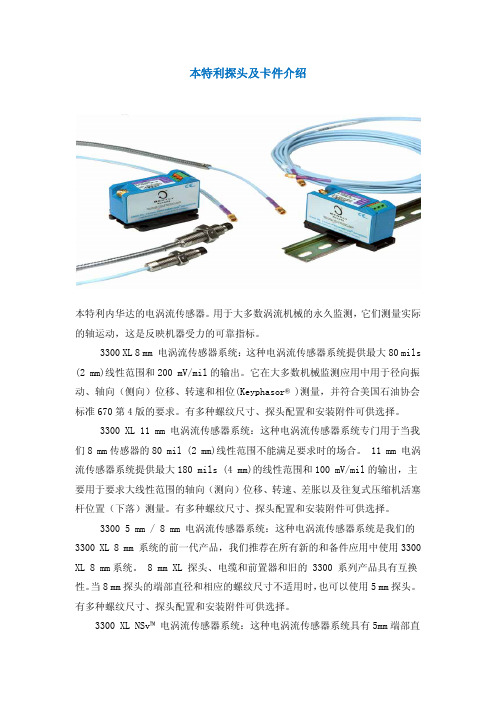
本特利探头及卡件介绍本特利内华达的电涡流传感器。
用于大多数涡流机械的永久监测,它们测量实际的轴运动,这是反映机器受力的可靠指标。
3300 XL 8 mm 电涡流传感器系统:这种电涡流传感器系统提供最大80 mils (2 mm)线性范围和200 mV/mil的输出。
它在大多数机械监测应用中用于径向振动、轴向(侧向)位移、转速和相位(Keyphasor® )测量,并符合美国石油协会标准670第4版的要求。
有多种螺纹尺寸、探头配置和安装附件可供选择。
3300 XL 11 mm 电涡流传感器系统:这种电涡流传感器系统专门用于当我们8 mm传感器的80 mil (2 mm)线性范围不能满足要求时的场合。
11 mm 电涡流传感器系统提供最大180 mils (4 mm)的线性范围和100 mV/mil的输出,主要用于要求大线性范围的轴向(测向)位移、转速、差胀以及往复式压缩机活塞杆位置(下落)测量。
有多种螺纹尺寸、探头配置和安装附件可供选择。
3300 5 mm / 8 mm 电涡流传感器系统:这种电涡流传感器系统是我们的3300 XL 8 mm 系统的前一代产品,我们推荐在所有新的和备件应用中使用3300 XL 8 mm系统。
8 mm XL 探头、电缆和前置器和旧的 3300 系列产品具有互换性。
当8 mm探头的端部直径和相应的螺纹尺寸不适用时,也可以使用5 mm探头。
有多种螺纹尺寸、探头配置和安装附件可供选择。
3300 XL NSv™ 电涡流传感器系统:这种电涡流传感器系统具有5mm端部直径和60 mils (1.5 mm)的更短线性范围,适用于被测靶面区域小、侧视或沉孔间隙减小以及其它限制使用我们标准的 5 mm / 8 mm 电涡流传感器的情况。
3300 16 mm 高温电涡流传感器系统:这种电涡流传感器系统用于最高350℃ (662°F)的高温环境,如温度超过我们标准电涡流探头和电缆能够承受的极限的某些燃气和蒸汽轮机应用。
电涡流传感器资料
第一章综述第一节系统简介为何采用电涡流位移传感器●电涡流位移传感器能测量被测体(必须是金属导体)与探头端面的相对位臵。
●电涡流位移传感器长期工作可靠性好、灵敏度高、抗干扰能力强、非接触测量、响应速度快、不受油水等介质的影响,常被用于对大型旋转机械的轴位移、轴振动、轴转速等参数进行长期实时监测,可以分析出设备的工作状况和故障原因,有效地对设备进行保护及进行预测性维修。
●从转子动力学、轴承学的理论上分析,大型旋转机械的运行状态主要取决于其核心——转轴,而电涡流位移传感器能直接测量转轴的状态,测量结果可靠、可信。
过去,对于机械的振动测量采用加速度传感器或速度传感器,通过测量机壳振动,间接地测量转轴振动,测量结果的可信度不高。
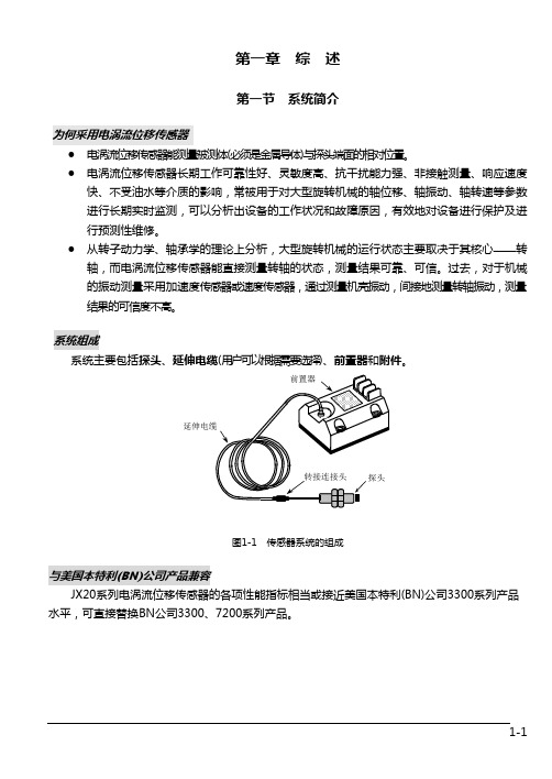
系统组成系统主要包括探头、延伸电缆(用户可以根据需要选择)、前臵器和附件。
图1-1 传感器系统的组成与美国本特利(BN)公司产品兼容JX20系列电涡流位移传感器的各项性能指标相当或接近美国本特利(BN)公司3300系列产品水平,可直接替换BN公司3300、7200系列产品。
1-1第二节 系统的工作原理传感器系统的工作机理是电涡流效应。
当接通传感器系统电源时,在前臵器内会产生一个高频电流信号,该信号通过电缆送到探头的头部,在头部周围产生交变磁场H 1。
如果在磁场H 1的范围内没有金属导体材料接近,则发射到这一范围内的能量都会全部释放;反之,如果有金属导体材料接近探头头部,则交变磁场H 1将在导体的表面产生电涡流场,该电涡流场也会产生一个方向与H 1相反的交变磁场H 2。
由于H 2的反作用,就会改变探头头部线圈高频电流的幅度和相位,即改变了线圈的有效阻抗。
这种变化既与电涡流效应有关,又与静磁学效应有关,即与金属导体的电导率、磁导率、几何形状、线圈几何参数、激励电流频率以及线圈到金属导体的距离等参数有关。
假定金属导体是均质的,其性能是线性和各向同性的,则线圈——金属导体系统的物理性质通常可由金属导体的磁导率μ、电导率σ、尺寸因子r ,线圈与金属导体距离δ,线圈激励电流强度I 和频率ω等参数来描述。
本特利探头说明书

质安全栅一起使用。当使用与电
源和信号通道处于同一位置的外
部安全栅时,平均灵敏度将降低
4%
机械特性
探头端部材料:
聚苯撑硫(PPS)
探头壳体材料:
AISI 304 不锈钢(SST)
探头电缆规格:
75 Ω 三轴, 氟乙烯丙烯(FEP) 绝缘电缆,1.0 米探头总长度
延伸电缆材料:
75 Ω 三轴, 氟乙烯丙烯(FEP) 绝缘
典型值 69.9 pF/m (21.3 pF/ft)
现场联线长度:
平均灵敏度: 线性范围:
推荐使用三芯屏蔽三股电缆。 在 3300 电涡流传感器和监测 器之间最长 305 米 (1,000 英 尺) 。当使用更长的现场联线 或外部安全栅距离监测系统有 一定距离时,高频信号衰减情 况参阅 3300 REBAM®手册
EExia IIC 对于 0、1 和 2 区, 组 IIC, BASEEFA 许可号 Ex94C2181X, 当安装本质齐纳 安全栅或电子绝缘器时。
T4 @ Ta=+100°C。 ExN 对于 2 区, 组 IIA、IIB 和 IIC,
BASEEFA 许可号 Ex94Y3183U
注:
MicroPROX® 应与本特利内华达本
Page 3 of 8
重量 (典型值): 0.59 kg (1.3 lbs)
探头:
117 g (4.1 oz)
延伸电缆:
180 g (6.3 oz)
铠装延伸电缆: 412 g (14.5 oz)
MicroPROX® 前 275 g (9.7 oz) 置器:
MicroPROX®
4 个直径 4.27 mm (0.168 in) 的孔,使用 M4 x 1 x 30 或 6-32 x 1.25 螺钉,以 50.8 mm (2 in)的孔中心距组成正 方形
