氨分解及纯化说明书
氨分解操作规程2
氨分解操作规程一、启动设备1、打开废气放散阀,打开电源,启动设备。
2、把氨分解开关拔至“开”的位置,将温度调至500℃,分解炉自动升温,待温度升至500℃时缓慢打开进氨阀,观察废气放空口是否有水泡,有无浓烈氨味。
3、温度升至给定温度(750℃~800℃,绝对不能超过810℃)时,适当加大流量。
(仍以放空口无浓烈氨味为准)4、打开取样口,嗅到是否有氨味,如果没有进行下一步操作,如果有看温度是否过低,导致分解炉分解不完全或是管道泄漏还是其它原因如果气体不合格,不能送往工作点,以免发生危险。
5、气体合格后,打开干燥器,在打开干燥器时,要注意进出阀是同一组,注意不要开错阀门。
6、打开流量计,根据用气单位用量,调节流量计关闭放散阀,调节出进气的压力。
二、停炉1、关闭所有进氨阀,再打开放空阀,使设备内的残余气体排至室外。
2、关闭分解炉电源,再关闭总电源。
3、待分解炉内残氨基本分解完毕后关闭。
否则由于残氨的分解引起压力升高,导致仪表设备损坏。
4、关闭所有阀门,整个装置尽可能地处于不与外部空气接触的状态。
便于下次使用时触媒不再活化。
纯化装置:关闭纯气出气阀,打开放空阀,关闭干燥器电源,等压力降到常压后关所有阀门。
三、注意事项1、氨气是具有刺激臭味的有毒气体,应防止泄漏,严禁人体与液体氨直接接触,以免冻伤如发现泄漏应戴上防毒面罩,用大量水冲进行处理。
2、检查分解炉电压电流是否过高,如果过高叫电工检查看是否加热丝被烧断或是短路。
3、要注意水的流量及仪表的变化,确保进出气的畅通。
4、在正常使用时,炉内氨气压力为0.2~0.5Mpa,不能超过0.5 Mpa。
5、在干燥器正常使用,根据气的用量,应在24h-48h转换一次温度应在300℃~350℃左右。
6、应在每天上班前检查一下气体的纯度。
7、如果流量浮子上下跳动检查流量是否过大过小。
8、使用已活化的分解炉时,进氨温度不要太低,应要达到500℃左右时才能送氨,以免活化镍触煤被毒化。
氨分解及气体纯化
江苏苏净集团有限公司氨分解与气体纯化设备使用说明书氨储罐内的液氨液面应严格控制,液面位置可通过外装的磁柱式液位计读出,这样可以保证氨储罐内的液氨有最大的蒸发面积,使氨储罐储氨和均匀压力的作用有一个良好的平衡。
汽化器在通电升温之前必须先通水。
首先打开出水阀门和进水阀门,使汽化器内充满水,然后关闭进水阀,出水阀常开。
汽化器工作通过电接点压力表(位于氨储罐上)对氨储罐内压力的控制实现对汽化器内电加热器通断的控制。
使用时,应先进行上下限设定,上下限范围为0.3-0.5Mpa。
在使用过程中必须保证不能断水,否则,将由于空烧现象而损坏汽化器。
2.氨分解炉第一次开机(分解炉触媒活化)准备工作结束后,便可进行开机。
氨分解炉,其炉胆出气口带有水冷却夹套,对法兰进行冷却保护,分解炉升温前应接通冷却水。
分解炉上的冷却水套中的冷却水必须是工业软化水。
绝对禁止高温情况下通入冷却水,因为过大的换热温差会使管道损坏。
分解炉升温前,应详细阅读温控仪的操作说明书。
控温时,监控温度设置应比温控设置高20℃。
接通电源,按电控箱电源开关,温控仪指示灯亮,分解炉加温指示亮。
观察电流表工作是否正常,设备开始加热升温。
打开放空阀,排污阀,使设备内的残余气体在升温过程中放空至室外。
分解炉中镍触媒活化要求控温和通氨程序见表:温度范围℃升温及保温时间 h 单台设备气氨流量m3/h 室温~200 4 0 200~500 8 0 500~600 6 10 600~700 4 20 700~800 4 30 800~850 4 50待炉温达到500~600℃时应缓慢打开减压阀前气氨进口阀,同时调定减压阀后压力,开始分解气的氨味很浓,待活化结束时可用鼻嗅,应无明显氨味,或观察气体燃烧时火焰呈桔红色,或用化学分析测定残氨小于0.1%,以示催化剂已得到充分活化。
催化剂活化过程中,减压阀应根据通氨流量要求逐步调节。
在正常工作情况下,应严格控制分解炉控温仪在800~850℃范围内。
氨分解制氢使用说明书

AQ-30
室温~500
3
3
3
3
0
0
0
0
500~600
2
2ห้องสมุดไป่ตู้
2
2
1
1
2
3
600~650
2
2
3
3
2
3
4
5
650~700
3
3
4
4
3
5
8
10
700~750
3
3
4
4
4
8
10
12
750~800
3
3
4
4
5
10
15
20
800~850
5
5
5
5
5
10
20
30
4.2.2.3干燥剂活化(再生)
表2.干燥剂活化(再生)
进口氨压力表突然上升管道上有霜
液氨贮罐上氨减压阀坏
氨水直接进入AF装置
换减压阀,管道上如无汽化器,必须立即加装汽化器
停机待修理完毕再开机
纯气指标差
1.原料气超标,不是一级品
2.纯气出口至工艺点管道洩漏
改善原料气指标
检查洩漏处,堵漏,如接口处漏,换垫片,拧紧螺纹接口
7.安全保护装置及事故处理
7.1电器安全
5.5 FC系列正常工作,阀门开关及电气开关见表5
表3. FC系列工作状态表
工作状态
1组工作
2组再生
1组工作
2组待用
2组工作
1组再生
2组工作
1组待用
阀工作1进、出
开
开
关
关
阀工作2进、出
氨分解气纯化调试20101222版

氨分解气纯化调试一、注意及要点1、严禁将氨分解不完全的气体通入纯化设备,强行通入会使纯化分子筛中毒而失去除水的能力。
2、严禁加热棒干烧;3、工作的干燥塔温度严禁超过80℃,超过80℃分子筛就失去了吸水的能力。
二、旋钮操作说明1、运行手动当“自动氮纯化手动”旋钮拨到手动位置时,“运行氮纯化停止”旋钮无用。
假如要求工作状态为Ⅱ塔工作、Ⅰ塔再生。
则将“Ⅰ干燥器工作Ⅱ”旋钮拨到Ⅱ位置,表示Ⅱ塔工作,此时Ⅱ塔工作进气阀、Ⅱ塔工作出气阀、Ⅰ塔再生进气阀打开。
“Ⅰ干燥器再生Ⅱ”拨到Ⅰ位置,表示Ⅰ塔再生,此时Ⅰ塔再生出气阀打开。
将“Ⅰ干燥器加热Ⅱ”旋钮拨到Ⅰ位置,此时Ⅰ塔开始加热,按照再生为加热8小时,吹冷16小时原则来做,8小时后将“Ⅰ干燥器加热Ⅱ”旋钮拨到中间位置,此时Ⅰ塔停止加热开始吹冷,16小时后将“Ⅰ干燥器再生Ⅱ”拨到中间位置,则Ⅰ塔停止吹冷。
此时,只有Ⅱ塔在工作。
根据实际情况考虑Ⅱ塔工作时间,比如工作气量比较小,则可以让Ⅱ塔多工作点时间。
工作时间原则上是与工作的气量成反比。
比如工作气量为额定气量的1/2,则工作时间可以多放大1倍。
自动当“自动纯化手动”旋钮拨到自动位置时,如系统内部数据未曾清零(清零情况为:刚刚为手动工作或“自动纯化手动”旋钮拨到手动位置超过5秒或在“自动纯化手动”旋钮指向自动位置时将“运行纯化停止”拨到了停止位置超过5秒),此时纯化上的“正常运行指示”将亮,系统将按照上次停机时的时间继续运行。
如系统内部数据清零,此时纯化上的“正常运行指示”不亮,则需将“运行纯化停止”旋钮拨到运行位置后让其自己复位,系统将从Ⅰ塔工作、Ⅱ塔再生开始运行。
如将“运行纯化停止”旋钮拨到运行位置后保持超过5秒,系统将从Ⅱ塔工作、Ⅰ塔再生开始运行。
2、纯化停止纯化停止时,将“自动纯化手动”旋钮拨到中间位置即可。
三、前期调试1、驱动气的压力保证4~6bar,前提是纯化的气动阀门能够正常的动作即可。
2、电磁阀、气动阀、工作塔的对应。
氨分解说明书

精心整理第一部分氨分解部分一、化工原理:1摩尔氨气在一定的压力和温度及镍触媒催化作用下可分解为1.5摩尔的氢气和0.5摩尔的氮气并吸收一定的热量。
气化学方程式如下。
2NH3→3H2+N2-Q1231、额定产气量:50立方米/小时2、气体纯度露点≤-103、分解炉操作温度800~850?C4、分解炉额定功率45kw5、额定氨耗20kg/h6、冷却耗量2.5立方米/小时7、电源50Hz380V8、设备总重3500kg五、操作方法:1、原始开车:1)仔细阅读使用说明书,熟悉设备的原理和构造。
2)检查气,电各系统是否通畅,消除泡,冒,点,漏,并接通电源。
3)镍触媒的活化:分解炉内装的镍触媒在出厂时已经还原,但因设备在运输,库存期间总有水分,氧气等介入,触媒活性略有下降,因此原始开车时要进行触媒的活化。
421)接通电源,温度在800~850?C为操作温度,温度已处于自动控制。
2)通氨放空:打开放空阀,然后慢慢打开进氨阀,使氨进入分解炉,约放空半小时。
3)正常送气:约放空半小时后,经样气检验合格后,即可打开分解气阀,向使用点送出合格分解气,并关闭放空阀,分解炉进入稳定运转状态。
4)停车:切断电源后先关进氨阀后再关分解气阀。
2日常维护:1)经常检查并消除泡,冒,点,漏,使设备处于完好状态。
2)经常检查自动温度控制仪,严防温控仪失灵。
一旦发生温控仪及热电偶测量失灵,应立即停车检修。
3)注意:严防有毒气体(如SPH2S极大量水气和氧气)进入分解炉,分解炉温度不能升的过高(一般不超过850?C),否则触媒活性很容易降低,甚至完全失去活性。
4)当分解炉短期停车(不通氨,不往外送分解气)需要保温时,温控仪温度设定在400?C以下,否则将使局部触媒因过热而烧坏。
5)触媒使用一段时间后,由于衰老而引起破碎现象,这种现象在气氨进口处尤为明显,它会6)2、保持装置气路系统的气密性,氨气有刺激性臭味,并且分解气有百分之七十五的氢气,氢气无色无味,却是易燃气体。
氨分解制氢使用说明书
表3. FC系列工作状态表
工作状态
1组工作
2组再生
1组工作
2组待用
2组工作
1组再生
2组工作
1组待用
阀工作1进、出
开
开
关
关
阀工作2进、出
关
关
开
开
阀再生1进、出
关
关
开
开
阀再生2进、出
开
开
关
关
纯气阀
开
开
开
开
纯化电源开关
开
关
开
关
转换开关
拨向2组
-----
拨向1组
AQ/FC系列装置上设有接地装置,请用户按4.1.3条实施可靠的接地作业。
7.2防火安全
请用户严格按1.3条作业,并在装置附近备有干粉及二氧化碳灭火器以备救急。
7.3工作人员不得在装置周围及废气排放口周围5米之内吸烟、打瞌睡,以确保人身安全。
8.维修和保养
8.1用户必须使用用户认可的合格人员进行设备的使用维修、保养,以保证人身安全和设备的安全。
热电偶短路
如电流表有电流显示热电偶工作正常则控温仪坏
换保险丝
换热电偶及接线
换热电偶及接线
调换温控仪
停电用万用表检查,换好元器件后再通电
电
流
表
a.无电流
b.电流突然上升至满刻度
电源是否正常
控制回路是否正常
导线接触不良
电热丝短路
电流表坏
查出原因
调换相应元器件
换电热丝
拧紧螺栓
换电热丝、炉板
换电流表
停电用万用表检查,换好元器件后再通电
NH3纯化器说明书

AERONEX® GAS PURIFICATION SYSTEM INSTALLATION AND OPERATING MANUALEGPS12SK Series8007934A October 2009AERONEX® GAS PURIFICATION SYSTEM Table of ContentsSection 1: System Functional Overview (1)1.1Equipment Specifications (2)Section 2: Safety Information (3)2.1 Precautionary Symbols (3)2.2 Safety Precautions (3)2.2.1General (3)2.2.2Gas (4)2.2.3Power (4)2.2.4Fire/Heat (4)2.2.5Seismic Restraint (4)2.3Safety Devices (4)2.3.1EMO Button (4)2.3.2Thermal Cut-Out Switches (5)2.3.6Rate of Temperature Rise Detector (5)2.3.3Remote Alarm Interface (6)2.3.4Enclosure Ventilation Pressure Switch (6)2.3.5Hydrogen Leak Detector (7)Section 3: System Installation and Removal (9)3.1Site Preparation (9)3.1.1General (9)3.1.2Wetted Materials (9)3.1.3Enclosure/Mounting (9)3.1.4Exhaust (10)3.1.5Power (10)3.1.6Instrument Air (10)3.1.7 Process Gas Input (10)3.1.8Process Gas Output (11)3.1.9Regeneration Gas Vent (11)3.1.10Regeneration Gas 1 (11)3.1.11Regeneration Gas 2 (11)3.1.12System Dimensions (12)3.2Tools/Equipment Required (Not Included) (13)3.3Installation Procedures (13)3.3.1Packing and Unpacking (13)3.3.2Transferring Weight from Casters to Levelers (13)3.3.2Process Piping Installation (14)3.3.3Power Installation - Standard (15)3.3.4Power Installation - Optional Connection of AC power to the Circuit Breaker (16)3.3Initial Power Up Procedure (17)3.5Leak Check Procedures (18)3.6Rotameter and Regulator Calibration (19)3.7 Bed Conditioning (20)3.8Equipment Start-Up (20)3.9Equipment Removal and Decomissioning (20)AERONEX® GAS PURIFICATION SYSTEMSection 4: System Operation (22)4.1Touch Screen Interface Overview (22)4.1.1 Main Screen (23)4.1.2Service Screen (24)4.1.3Swap Function (25)4.1.4 Condition Bed A and Condition Bed B Button (25)4.1.5View Logs Screen (26)4.1.6File Ops Screen (27)4.1.7Configure (28)4.2Audible Alarm Silencing Feature (28)4.3Alarm Descriptions (29)4.4Alarm Troubleshooting Guide (29)4.4.1 Leak Detected (29)4.4.2 Pic EEprom for Parameter Storage Full (29)4.4.3 EMO Detected (30)4.4.4 Gas Pressure Below Threshold (30)4.4.5 Bed A/B High Limit Exceeded (30)4.4.6Bed A/B Low Limit Exceeded (30)4.4.7 Regen No Flow (30)4.4.8 Bed A/B Regen Temperature Minimum Exceeded (30)4.4.9 Bed A/B Regen Temperature Maximum Exceeded (30)4.4.10 RTC Clock Time Invalid (31)4.4.11 Both Beds Need Regen (31)4.4.12 Power Supply Out of Tolerance (31)4.4.13 Stepping Rules Violation (31)4.4.14 Ventilation Flow Below Minimum (31)4.4.15Fire Detected (31)Section 5: System Features (32)5.1Pictures (32)5.1.1Front View (32)5.1.2Mechanical Overview (33)5.1.3Top View (34)5.1.4Electrical Enclosure (35)5.1Options (35)5.2.1Automatic Bypass (35)5.2.2Manual Bypass (35)5.3Spare Parts (36)5.4 Required System Maintenance (36)5.5Customer Service Contact Information (36)Section 6: Material Safety Datasheet (MSDS) (38)Section 1: Product and Company Information (38)Section 2: Composition / Information on Ingredients (38)Section 3: Hazards Identification and Emergency Overview (38)Section 4: First Aid Measures (39)Section 5: Fire-Fighting Measures (39)Section 6: Accidental Release Measures (39)AERONEX® GAS PURIFICATION SYSTEMSection 8: Exposure Controls/Personal Protection (40)Section 9: Physical and Chemical Properties (40)Section 10: Stability and Reactivity (40)Section 11: Toxicological Information (41)Section 12: Ecological Information (41)Section 13: Disposal Considerations (41)Section 14: Transport Information (41)Section 15: Regulatory Information (41)Section 7: Glossary (44)AERONEX® GAS PURIFICATION SYSTEMAERONEX ® GAS PURIFICATION SYSTEM Section 1: System Functional OverviewDANGER! Carefully review the safety information in Section 2 before installing or powering up the system.The Aeronex ® EGPS12SK is an ammonia gas purification system that uses ambient temperature technology to remove contaminants such as H 2O, CO 2, and O 2 to sub-ppbv (parts per billion by volume) levels.The Aeronex® EGPS12SK uses two purifier beds in parallel to maintain a continuous flow of purified gas. One purifier bed is online while the other is in either regeneration or stand-by mode.A microprocessor controls all automated processes,including the purification, regeneration, and mode switching functions. It also provides system status monitoring and support for user interface activities. The purification process occurs at ambient temperature. The media within the purifier bonds to contaminants in the gas stream by chemisorption and adsorption. The proprietary regeneration process renews the capacity of the off-line purifier. A hot gas is driven through the purifier media to break the bonds that hold the contaminants and carry them away. When the bed returnsto ambient temperature, it is placed in a stand-by mode, and is ready to go back online.Power failure will not damage the purifier system.EGPS12SK Process and Instrumentation Diagram (P & ID)AERONEX ®GAS PURIFICATION SYSTEM 1.1 Equipment SpecificationsGas type:NH 3 (Ammonia) Maximum flow rate:400 slm (840 scfh) Maximum inlet pressure:150 PSIG (10 bar, 1034 kPa) Maximum pressure differential: 200 PSID (13.8 bar, 1380 kPa) Pressure drop:17 PSIG at maximum flow and 90 PSIG 1.172 bar at maximum flow and 6 bar 117 kPa at maximum flow and 600 kPa Contaminants removed:H 2O, O 2 and CO 2 H 2O:<1 part per billion (ppbv) O 2:<1 part per billion (ppbv) Outlet purity as measured in N 2: CO 2:<1 part per billion (ppbv) Process Gas Piping Leak Rating:1 × 10⁻⁹ std cc/sec Regeneration Vent Manifold LeakRating:1 × 10⁻⁴ std cc/secAERONEX® GAS PURIFICATION SYSTEMSection 2: Safety InformationThe safety information below applies to all sections of this manual. Hazard and safety information is particularly applicable during system installation and removal, but it also applies to troubleshooting and alarm-related activities that can occur in an installed system.To draw the reader’s attention to known potential safety hazards, this manual uses the safety symbols listed in Section 2.1 below. Look for them and read the safety precautions and instructions they flag. Be aware of potential hazards before undertaking an installation or repair activity.Some standard precautions apply with all systems that process potentially hazardous materials. Installers and operators should know how to avoid or manage any potential hazards they could encounter. Personnel should be trained what to do in case of serious gas leaks or other emergencies, and any safety clothing or equipment that might be needed in an emergency should be ready for immediate use. For additional detailed information about safety management for the gasses processed by this product, see the Material Safety Datasheets in Section 6.2.1 Precautionary SymbolsThe safety symbols appear in any context where a known potential hazard could exist. Safety information appears in the form of NOTES, CAUTIONS and WARNINGS as described below. It is important that you operate your equipment in accordance with this instruction manual and any additional information that Entegris, Inc. may provide. Address any questions regarding the safe and proper use of your equipment to Entegris. See Section 5.5 for contact information.Symbol HazardDescriptionNOTE: Provides information to aid you in obtaining optimal performance from your instrument.DANGER! Indicates a hazardous situation that, if not avoided, could result in death orserious injury.WARNING! Indicates a potential hazardous situation that, if not avoided, could result indeath or serious injury and/or irreparable damage to the equipment.CAUTION! Indicates a potential hazardous situation that, if not avoided, could result inminor to moderate injury and/or minor to moderate damage to the equipment.WARNING!BURN HAZARDVery hot surface may be exposed. Use proper skin protection.WARNING!SHOCK HAZARDHazardous voltages are present inside the system. Disconnect from main powerbefore opening the enclosure.2.2 Safety Precautions2.2.1 GeneralWARNING!This equipment requires mechanical lifting.• Personal Protective Equipment (PPE) is not required to operate this equipment.• When servicing this equipment, use proper PPE for electrical and/or gas panel equipment. All PPE should be used in accordance with the manufacturer’s instructions.• The purification materials contained within the stainless steel purifier vessels may be deemed hazardous materials. In the unlikely event of an accidental release, refer to the Material Safety Datasheet (MSDS) located in Section 6 for first-aid recommendations and appropriate cleanup measures. Refer to Section 6 for more information on the material contained in the equipment.AERONEX® GAS PURIFICATION SYSTEM 2.2.2 GasDANGER!Do not expose this equipment to incompatible gases. (Refer to Section 10 of the MaterialSafety Datasheet for details.)• It is important to know the hazards associated with compressed gases and understand the physical and chemical properties of the gases being used.• Follow proper safety and handling guidelines for compressed gas. Consult your gas supplier for assistance and guidance.• This equipment may be used with gases up to 150 PSIG (11.3 bar, 1130 kPa). If it is necessary to open any internal connection, ensure the system is properly decommissioned. (See Section 3.9).Previously pressurized vessels or piping will continue to hold pressure until vented.2.2.3 PowerWARNING!A qualified electrician is required for electrical installation.• A circuit breaker with lockout tag-out capability is provided with this equipment.• High voltage circuitry, including the AC power wires, AC connector and the contents of the electrical enclosure, is contained within the equipment enclosure, and represents an electrical shock hazard. Remove power at the main disconnect before servicing.• The circuit breaker is rated at 10 AMPS, 240 VAC, and 14000 AIC.2.2.4 Fire/HeatWARNING!High temperature components are present within the equipment enclosure, including theinsulated blankets and stainless steel plumbing elements that could cause a burn injury.After a shut down, allow these components to cool before touching them.2.2.5 SeismicRestraintWARNING!This equipment must be installed with locally approved seismic mounts, and may berestrained via the four holes on the bottom of the enclosure.2.3 SafetyDevicesThe Aeronex® EGPS12SK includes several safety devices to ensure safe operation of the equipment. Triggering of the devices described below will place the system into a safe EMO condition.In Standard mode, during an EMO shutdown condition:• All hazardous potentials are restricted to the electrical enclosure.• Hazardous voltages are removed from the main enclosure, except the circuit breaker. Power continues to the controller board and user interface to provide support for system diagnostics. • The flow of hazardous material through the equipment is stopped.• All pneumatic valves are automatically closed.• The auto-bypass valve, if installed, is opened.• Internal heat sources are shut off.• The equipment presents minimum hazard to personnel or the facility.2.3.1 EMOButtonUnless otherwise specified, the Emergency Off (EMO) function is factory set to the default setting of “Standard,” which is described above. An alternative “Japan” option is described below.1. The EMO button allows the user to quickly shutdown the system in the event of an emergency.2. To trigger an EMO shutdown, press the button inuntil it clicks into position.3. To deactivate the button when the condition hasended, turn it clockwise until it clicks intoposition.4. To clear the alarm and resume normal operation,press the Start / Clear button below the EMObutton.The “Japan” setting causes the following conditionsEMO Buttonto occur when the EMO button is activated:• The EMO shuts off power to the entire system, including the electrical enclosure. The only remaining power shall be at the circuit breaker outlet.• Hazardous material flow through the equipment is stopped.• All pneumatic valves are automatically closed; auto-bypass valve, if installed, is opened. • Internal heat sources are shut off.• Equipment presents minimum hazard to personnel or the facility.To activate the “Japan” EMO function, contact your local field applications engineer.2.3.2 Thermal Cut-Out SwitchesDuring regeneration, the gas temperature of thepurifier beds must remain within set limit. Thethermal cut-out switches monitor the temperatureto detect a thermal run-away condition.If one of the following occurs, one of the thermalcut-out switches will trigger an EMO shutdown:1. There is a thermal run-away condition in theregenerating purifier bed.2. The regeneration flow rate has been set toohigh and the rotameter needs resetting.Thermal Cut-Out SwitchThese switches require no maintenance.2.3.6 Rate of Temperature Rise DetectorThe rate of temperature rise detector is designedto detect a rapid increase in internal temperaturein the cabinet, or hazardous temperature.The normal ambient air temperature for operatingthe equipment must be between 15° and 40°C.The rate of rise detector will trigger an EMOshutdown if either of the following occurs:• The sensor detects an excessive temperature.• Internal enclosure temperature rises rapidly.The rate of temperature rise detector requires noRate of Temperature Rise Detector maintenance.2.3.3 Remote Alarm InterfaceThe remote alarm interface allows the external process tool or customer facilities to communicate with the Aeronex® system.The remote alarm interface has three functions: 3. EMO Output – This output indicates to theexternal device that the Aeronex® system has entered an EMO condition and all systemfunctions have been halted.4. Alarm Output – This output indicates to theexternal device that the Aeronex® system has entered either an EMO condition or a non-EMO alarm condition.5. EMO Input – This input allows the externaldevice to remotely place the Aeronex® system into an EMO condition. After this input is nolonger active, it is necessary to press theStart/Clear button to restart the system. Signal Type Dry ContactElectrical Rating 30 VDC, 1A Maximum Recommended WireSize22 AWG Equipment ConnectorTypeFemale 15 pin D-SubAlarm Output Pins 4 and 12 (normally closed) EMO Output Pins 5 and 13 (normally closed) EMO Input Pins 6 and 14 (normally closed) Remote Alarm InterfaceFemale 15 pin D-Sub Connector DiagramNOTE: Since the Dry Contacts are all normally closed contact types, several jumpers must be removed from the electrical enclosure before using this feature. Contact your local Entegris Field Applications Engineer for assistance..2.3.4 Enclosure Ventilation Pressure SwitchThe pressure switch will detect the loss of exhaust flow through the cabinet. For normal operation:1. The front panel must be securely installed.2. Internal static pressure must be between -0.1to –0.15 inches H2O.3. The pressure switch bypass switch must be inthe “ONLINE” position.The pressure switch will create an EMO conditionif either of the following occurs:• The internal static pressure indicates reducedexhaust flow (i.e., is not at least – 0.1 inchesof H2O).• Front panel is removedThe pressure switch can be placed into a “BypassMode” using the pressure switch bypass switch.This mode is used for any maintenance operationthat requires removal of the front panel whilepower remains on.Pressure SwitchTo enter the switch bypass mode, toggle the pressure switch bypass switch to “BYPASS.”NOTE: In “Bypass Mode” the system can only perform service mode operations. The system will NOT go into online or regeneration functions.Pressure Switch Bypass Switch2.3.5 Hydrogen Leak DetectorThe hydrogen leak detector is designed to prevent an explosion hazard by sounding an early warning if a hydrogen gas leak occurs in the equipmentenclosure.The hydrogen leak detector has a normal warm-up period of approximately 2 minutes. (In rareconditions, the sensor may take up to 60 minutes to warm up.) During this period, the detector will appear to be in a failed mode and will generate an “H 2 Leak Detected” alarm. This is the normal operation of the detector. After the warm-up period, the Start/Clear button must be pressed to clear the alarm and start normal operation. For normal operation:Hydrogen Leak Detector1. The equipment must be installed in a normal atmospheric air environment. Any abnormalconcentrations of trace gases may affect system performance. 2. The relative humidity must be between 0-90% non-condensing in the room where the equipmenthas been installed. The hydrogen leak detector will create a standard EMO condition if any of the following occurs:• There is an excessive H 2 (Hydrogen) leak in the equipment enclosure. • The relative humidity has exceeded the specifications for the equipment.• The equipment has been installed in an excessively dirty environment, and the hydrogen leak detector has been damaged by debris settling on the sensor surface. •There is excessive ambient H 2 (Hydrogen) in the environment.The hydrogen leak detector requires annual replacement to maintain proper calibration. The actual replacement schedule should call for more frequent replacements if ambient H 2 (Hydrogen) is prevalent in your installation location. Contact your local Entegris Field Applications Engineer for more information.Section 3: System Installation and Removal3.1Site Preparation3.1.1 GeneralCAUTION!The Aeronex® EGPS12SK should be installed by a qualified mechanical and electricalcontractor who is familiar with the installation of complex equipment and high-purity gas delivery systems.This section provides information to assist a qualified installer in preparing the site for systeminstallation. It specifies the space required to accommodate the unit; the sizes, locations, and types of the various pipes required to process gas inputs and outputs; power requirements; etc. Where noted, failure to meet the requirements can void the warranty of your equipment.CAUTION!This equipment provides lockout tag-out capability. The user must provide a means to disconnect power from the system with lockout/tagout capability according to local code requirements (See Section 2.2.3).All connections are made either on top of the enclosure or through the top of the enclosure. Refer to the Process Piping Installation instructions in Section 3.3.2 and the dimensional drawings in Section 3.1.12 of this manual.3.1.2 Wetted MaterialsFor all piping used to pass wetted materials into or out of the EGPS12SK, use only 316L stainless steel tubing and connections that have been internally electro-polished with a 10Ra or better internal surface finish. Failure to do so may void the warranty.CAUTION!Failure to use 316L SS piping may introduce contaminants to the process piping and may void the warranty of the purifier.3.1.3 Enclosure/MountingCAUTION!To ensure safe system operation, in accordance with Semi S2 or applicable building code requirements, level and secure the enclosure using provided restraint holes (noted in Section 3.1.12) before final installation.Parameter Specification TypeNEMA 12 (indoor use only) - Cleanroom compatible Required Space Refer to Section 3.1.12 Weight450 lbs 205 kg Temperature 60° ~ 104°F15° ~ 40°CAmbient AirNormal atmospheric air; any abnormal concentrations of trace gases may affect system performanceOperating EnvironmentIndoor installation only, dust controlled environment10% ~ 90% Relative Humidity / Noncondensing (failure to meet this requirement may cause premature failure of the equipment)3.1.4 ExhaustParameter Specification Static Pressure -(0.10) to -(0.15)inches of H 2O -(0.25) to -(0.37) mbar -(25) to -(37) Pa Minimum Flow 65 cfm110 m 3/hr 1840 slm Connection TypeVentilation ductConnection Size 4 inches diamter102 mm diameter3.1.5 PowerWARNING!A qualified electrician is required for electrical installation of this equipment.Parameter Specification Power 200-240 VAC, 1000 Watts, 50-60 Hz 3.1.6 Instrument AirCAUTION!Pressure greater then 100 PSIG may cause damage to the equipment.Parameter Specification Gas Type Clean Dry Air or Nitrogen (N 2) Minimum Pressure 80 PSIG 6.5 bar 650 kPa Maximum Pressure 100 PSIG 7.9 bar 790 kPa Inlet Filtration 5 micron Connection Type Compression Connection Size 1/4 inchRecommended Equipment 1/4 inch, 0-100 PSIG pressure regulator, manual isolation valve3.1.7 Process Gas InputParameter Specification Gas Type NH 3 (Ammonia) Minimum Flow Rate (required duringregeneration process) 200 scfh 100 slm Maximum Flow Rate 840 scfh 400 slm Minimum Pressure 60 PSIG 5.1 bar 510 kPa Maximum Pressure 150 PSIG 11 bar 1100 kPaH 2O:9 ppmv O 2: 5 ppmv Maximum Inlet Challenge atmaximum flowrate, maximum pressure, 100% duty cycle andminimum regeneration interval * CO 2:1.3 ppmvInlet Filtration0.1 micron or better Incompatible Gases O 2, CDA (Air), NF 3, SF 6 Connection Type Tube Stub Connection Size 3/4 inchRecommended Equipment3/4 inch manual isolation valve* The inlet challenge can be greater than listed if the equipment is operated at less than the maximum flow rate, less than the maximum pressure, less than 100% duty cycle.3.1.8 Process Gas OutputParameter SpecificationGas Type NH 3 (Ammonia) Connection TypeTube stub Connection Size 3/4 inchRecommended Equipment 3/4 inch manual isolation valve3.1.9Regeneration Gas VentCAUTION!Back pressure on the Regeneration Gas Vent may cause damage to the equipment. Ensure that the line is at atmospheric pressure or less for proper operation. (See 2.3.4)WARNING!The Regeneration Gas Vent may require treatment or control (i.e. scrubber) due to toxicity, flammability or other potential hazards. Please consult with your Environmental, Health, and Safety personnel for regulatory compliance.Parameter Specification Gas Type N 2 (Nitrogen), H 2 (Hydrogen), NH 3 (Ammonia)Maximum Pressure VentOutlet14 PSIG 2 bar 200 kPa Connection Type Tube Stub Connection Size ¼ inchRecommended Equipment Gas scrubber 3.1.10 Regeneration Gas 1Parameter Specification Gas Type N 2 (Nitrogen) Minimum Required Flowrate127 scfh 60 slm Minimum Pressure 65 PSIG 5.5 bar 550 kPa Maximum Pressure 100 PSIG 7.9 bar 790 kPaInlet Purity 99.999% PSIG Inlet Filtration <0.003 micron Connection Type Tube Stub Connection Size ¼ inchRecommended Equipment ¼ inch manual isolation valve 3.1.11 Regeneration Gas 2Parameter Specification Gas Type H 2 (Hydrogen) Minimum Required Flowrate21 scfh10 slmMinimum Pressure 65 PSIG 5.5 bar 550 kPa Maximum Pressure 100 PSIG 7.9 bar 790 kPaInlet Purity 99.999% PSIG Inlet Filtration <0.003 micron Connection Type Tube Stub Connection Size¼ inchRecommended Equipment¼ inch manual isolation valve3.1.12 System DimensionsDimensions are in millimeters [inches].3.2 Tools/Equipment Required (Not Included)NOTE:The customer or installer is responsible for providing the equipment listed below.Qty Description Function1 3/4 inch open end wrench 1/4 inch face seal fitting1 5/8 inch open-end wrench 1/4 inch face seal andcompression fitting1 9/16 inch open-end wrench 1/4 inch compression fitting 1 15/16 inch open-end wrench 1/2 inch face seal fitting1 1 1/16 inch open-end wrench 1/2 inch face seal fitting1 1 inch open-end wrench Removal of power receptacle 1 helium leak detector with helium gas source, capable of testing to1 x 10-9 std cc/secleak check1 manometer (pressure measuring device for ventilation duct) ormagnahelicventillation verification1 orbital welding machine with ½ and ¼-inch welding capability process piping installation 1 #2 Phillips-head Screwdriver For panels1 ¼ inch Flat-head Screwdriver For power connector4 1/4 inch nickel face seal gaskets, unplated (VCR type)For test ports and rotameter4 1/2 inch nickel gaskets, unplated Face seal fittings3.3 InstallationProceduresWARNING!Avoid back strain or injury by following all safety precautions when lifting heavy objects.Handling and installation this equipment requires a minimum of two people.Ensure that all of the requirements outlined in Section 3.1 are met.3.3.1 Packing and UnpackingTo ensure safe delivery, the equipment packaging complies with International Air Transportation Association (IATA) and International Civil Aviation Organization (ICAO) requirements. You may want to keep the packaging for future shipping purposes, if applicable. Due to the weight of this unit, we recommend using a forklift or pallet jack for transportation.3.3.2 Transferring Weight from Casters to LevelersWhile the enclosure isdesigned for floor mounting,it can be secured using themounting holes located onthe bottom of theequipment, with the weighttransferred from the castersto the levels and leveledbefore the piping and electrical connections are made. Use hardware suitable for the unit weight and your applicable building code. Rolling Setting:Rotate the red adjustment knobclockwise to raise the levelingpad up towards the enclosure.This will transfer the weight ofthe EGPS12 from the levelingpads to the casters.Level Setting:Rotate the red adjustment knobcounter-clockwise to lower theleveling pad towards the floor.This will transfer the weight of theEGPS12 from the casters to theleveling pads.3.3.2 Process Piping InstallationCAUTION!Failure to use 316L SS piping may introduce contaminants to the process piping, and may void the warranty of the purifier.WARNING!Do not flow gas into the equipment until a Helium leak test has been performed. Refer to Section 3.5.1. Install the ¼-inch line to the compressionfitting for the instrument air connection. (See section 3.1.6 for specification) 2. Install the 4-inch exhaust plumbing to theexhaust duct. (See section 3.1.4 for specification) 3. Install process inlet connection.• Remove the system front panel. •Connect purge gas device to upstream leak test port. Refer to Section 5.1.2 for location.• Orbital weld process inlet into place (on top of unit).•Disconnect purge gas and install a new ¼-inch nickel gasket into the upstream leak test port and secure into place. 4. Install process outlet connection.•Connect purge gas device to the downstream leak test port. Refer to Section 4.3 for location. • Open manual the isolation valve. • Orbital weld process outlet into place (on top of unit).•Disconnect purge gas and install a new 1/4 inch nickel gasket in the downstream leak test port and secure into place. • Close manual isolation valve.5. Install Regeneration Gas 1 Connection•Open the upper face seal fitting of the 1/4 inch check valve in the Regeneration Gas 1 line.NOTE: Do not open the lower fitting on the check valve. This fitting contains a gasket-style orifice.•Connect purge gas to customer supplied upstream piping and purge through opened fitting at the check valve.Note: Dimensions are in millimeters [inches]. Process Piping Dimensions。
氨分解的基本操作

氨分解的基本操作1开机前的准备工作:1、准备200kg/瓶的液氨2瓶。
2、提供能够承受电压交流380V,50Hz,功率40Kw电源,机壳接地。
3、检查电气元件接头处有无松动,例如:电流表、温控仪、电炉、热电偶、交流接触器、熔断器等所有电气元件。
2原始开机1、打开废气放空阀,接通电源,此时总电源指示灯亮。
2、将氨分解开关拨向“开”位置,设定温控仪温度200℃(升温曲线见下表、温控仪设定见温控仪说明书)进行镍触媒活化,分解炉内装的镍触媒在出厂时已经还原,但因设备在运输,库存期间总有水分、氧气等介入,镍触媒活性略有下降,因此原始开机时还要进行镍触媒的活化。
镍媒的活化将关系到镍触媒的分解效果及寿命,请严格按照上表操作!样气检验:可用化学分析或经验方法,其中经验方法是从放空口嗅不到明显的氨臭味或观察分解气燃烧时,火焰呈橙色,若符合上述现象则分解气合格。
3、干燥器内5A分子筛活化再生:氨分解开车正常后,取小部分合格的氢、氮混合气送入干燥器Ⅱ,吸附干燥其中的水分、残氨(处低负荷工作),利用这部分气体来加热冲洗干燥器Ⅰ中的5A分子筛,此时干燥器升温选择开关拨向Ⅰ组,这部分气体经“再生Ⅰ出”阀放空。
具体操作如下:打开阀“工作Ⅱ进”、“工作Ⅱ出”、“再生Ⅰ进”、“再生Ⅰ出”,并调节再生流量处于3m³/h。
将干燥器升温选择开关拨向Ⅰ组,其升温过程如下。
4、干燥器Ⅰ活化(再生)结束后,所有阀门不变,只需关掉Ⅰ组的加热开关,就可继续用干燥器Ⅱ纯化的小气量吹冷干燥器Ⅰ至室温(也可让Ⅰ组干燥器自然冷却至室温):然后关闭“工作Ⅱ进”、“工作Ⅱ出”、“再生Ⅰ进”、“再生Ⅰ出”,Ⅰ组干燥器即可正常工作。
5、Ⅱ组干燥器再生活化步骤与Ⅰ组相同,但阀门相应变为“工作Ⅰ进”、“工作Ⅰ出”、“再生Ⅱ进”、“再生Ⅱ出”。
3正常开机:氨分解部分:1、打开废气放空阀,接通电源,此时总电源指示灯亮。
2、将氨分解开关拨向“开”位置,设定温度仪温度200℃,分解炉自动升温,待温度升至200℃时,保温1小时,再设定温控仪温度400℃,分解炉自动升温,待温度升至400℃时,保温1小时,再设定温控仪温度600℃,分解炉自动升温,待温度升至600℃时,保温1小时,再设定温控仪温度800℃,分解炉自动升温,待温度升至800℃时,保温半小时,打开进氨阀,调节减压阀压力,略开打压力阀(减压阀逆时针减下,顺时针增大),观察废气放空口,有气流出,将该放空口的放空管放入水中,注意水泡产生现象,此时,温控仪的温度会慢慢下降,为正常现象。
氨分解纯化装置使用说明书

FC系列气体纯化装置采用分子筛吸附剂进行变温吸附,除去氨分解气中的水汽和残氨、并经过滤器后除去尘埃颗粒。
本装置与AQ系列液氨制氢炉配套使用,从而使产品达到净化目的。
一.主要技术性能:⒈处理气量: 30m3/h⒉原料气体: 75%H2 25%N2、杂质残氨<1000PPm 、露点<-10℃⒊纯化后气体:残氨≤5PPm、露点≤-60℃⒋纯气出口压力:<0.2MPa⒌工作温度:常温再生温度:<350℃⒍工作周期: 24h×2⒎功率: 12.5kw⒏冷却水量: 0.3 t/h二. 开箱栓查和设备安装:⒈装置开箱后,应按装箱清单检查备件、附件和使用说明书等有关物件,根据工艺流程图接通装置的原气进口、纯气出口和废气放空口;并接通冷却器的水进出口和排污口。
若用户用氮气来进行干燥器的再生,需接通装置的氮气进口。
⒉用氮气充压至0.2Mpa,在各管道连接处以肥皂水涂沫检漏应无泄漏现象,待压力平衡后,保持24h,观察压力降<0.05Mpa(环境温度变化也会引起系统压力变化)。
⒊检查电气接线有无松动、脱头现象,热电偶、温控仪能否正常工作,热电偶应插到底,温控仪应能自动控温。
⒋接通电源三相380V、50HZ(机壳必须接地)。
三. 工艺流程:本装置为复式流程。
用四只吸附干燥器,两只工作时,另两只再生,以保证连续运行。
干燥器在常温下工作,充气并加温至<350℃再生。
原料氨分解气体通过冷却器降温后,经阀V01(V02)进入干燥器Ⅰ(Ⅱ),利用分子筛对氨和水的共吸附,可以同时除去残氨和水份,然后净化后的气体经阀V05(V06)、过滤器、纯气流量计FI-01、阀V13由纯气出口送至使用点。
与此同时,过滤器后的一部分纯气经阀V09、再生流量计FI-02、阀V08(V07)进入干燥器Ⅱ(Ⅰ)内筒,被加热至300℃左右,热气流经过分子筛床层,从而使分子筛加热再生。
用户也可以用氮气来进行干燥器的再生,此时只需关闭阀V09、打开阀V11。
FHQ-120氨分解说明书

FHQ系列氨分解制氢装置目录第一部分安全第二部分设备描述第三部分设备的基本操作第四部分系统维护及保养第五部分常见故障及其排除第六部分附页第一部分安全1.1氢气1.1.1氢气的特性:FHQ系列氨分解气体发生装置是以液氨为原料,在一定的压力、温度及镍触媒的催化作用下,可分解出含氢气75%和含氮气25%的混合气体。
此气体是一种无色、无味、无嗅、易燃易爆气体,它和氯、氧、一氧化碳及空气的混合物有爆炸危险。
下面给出的是氢和各种混合物的爆炸极限:氢和空气混合物的爆炸限:4X10⁻²~75X10-2(氢);氢和氧混合物的爆炸限:4X10⁻²~95X10-2(氢);氢和一氧化碳混合物的爆炸限:13.5X10⁻²~49X10-2(氢);氢和氯的混合比为1:1时,在光照下即可爆炸。
在氢气氛中,人有被窒息的危险,因而在氢含量有可能增加的地方应设有通风装置。
必要时应设有氢气警报仪,以对氢气含量进行监测。
检修或处理氢气管道、设备、气瓶之前,必须先用氮气将氢气置换到符合动火规定,方能开始工作。
由于氢气的存在不易被感官发现,氢气的点火能很小,爆炸能很高,因而在使用和贮运时要严加注意!1.1.2氢气系统运行安全要点:1、输入系统的氢气含氧量不得超过0.5%。
2、氢气系统运行时,不准敲击,不准带压修理和紧固,不得超压,严禁负压。
3、管道、阀门和水封装置冻结时,只能用热水或蒸汽加热解冻,严禁使用明火烘烤。
4、设备、管道和阀门等连接点泄漏检查,可采用肥皂水或携带式可燃性气体防爆检测仪禁止使用明火。
5、不准在室内排放氢气。
吹洗置换,放空降压,必须通过放空管排放(一般氢气贮罐的放空阀、安全阀和管道系统均应设放空管)。
放空管的要求:①放空管应采用金属材料,不准使用塑料管或橡皮管。
②放空管应设阻火器,凡条件允许,可与灭火蒸气或惰性气体管线连接,以防着火。
③室内放空管的出口,应高出屋顶2米以上。
室外设备的放空管应高于附近有人操作的最高设备2米以上。
氨分解安全操作规程标准范本

操作规程编号:LX-FS-A76709 氨分解安全操作规程标准范本In The Daily Work Environment, The Operation Standards Are Restricted, And Relevant Personnel Are Required To Abide By The Corresponding Procedures And Codes Of Conduct, So That The Overall BehaviorCan Reach The Specified Standards编写:_________________________审批:_________________________时间:________年_____月_____日A4打印/ 新修订/ 完整/ 内容可编辑氨分解安全操作规程标准范本使用说明:本操作规程资料适用于日常工作环境中对既定操作标准、规范进行约束,并要求相关人员共同遵守对应的办事规程与行动准则,使整体行为或活动达到或超越规定的标准。
资料内容可按真实状况进行条款调整,套用时请仔细阅读。
1、氢气是一种易燃易爆气体,因此必须绝对防止氢气泄漏在室内和接触明火,必须使操作环境通风良好。
2、制氢站严禁烟火,设置禁火标志。
3、原料液氨应防止泄漏,如发生泄漏时,处理人员处理时应戴防毒面具,同时应避免液氨的随意排放。
4、制氢站内所有设备均应可靠接地,并定期检查。
5、原料氨通入分解炉,分解出的气体未经纯化或纯化不合格时,不可送入生产线,以免影响生产及产品质量。
6、必须随时注意各电器及加热控制温开关工作是否正常,以免烧坏设备,影响生产。
设备停机时间较长或需检修时,应经氮气吹扫,使全系统中的残氢量《0.5%为止,保证设备的安全及避免着火或爆炸。
请在该处输入组织/单位名称Please Enter The Name Of Organization / Organization Here。
氨分解操作规程

氨分解操作示意图
1、打开排污阀→分解炉电源打开→开始升温。
升温曲线看下表:
2、温度升到800℃,排污口气量很大,也没有较浓氨味方可进入纯化:
关闭排污阀→打开1组工作进→打开1组工作出→打开纯气出口阀再打开2组再生阀进→2组再生阀出→调节好再生流量5㎡(取纯气的十分之一再生)→再打开纯化电源→把转换开关拨向2组→温度调到250-300℃
3、纯化工作周期是24小时。
纯化温度250-300℃,升温及保温时间8小时,8小时后把纯化电源关闭,其它阀门不变,16小时冷却
4、工作24小时后,把2组再生进关闭→2组再生阀出关闭→打开2组工作进→打开2组工作出→关闭1组工作进→关闭1组工作出→再打开1组再生进→1组再生出→调节好再生流量5㎡→再打开纯化电源→把转换开关拨向1组→温度调到250-300℃
5、24小时后再转换到另外1组
精选。
氨分解炉操作指导书
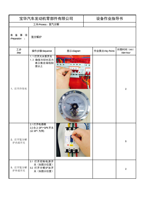
宝华汽车发动机零部件有限公司设备作业指导书工序/Process:氨气分解准备事项/Preparation:氨分解炉工步Step 操作步骤/Sequence 图示/Diagram作业要点/Key Points所需时间(min)Man-hour1、打开冷却水1.1打开大水泵开关1.2 确保冷却水压力表示数在绿线刻度以上22、打开氨分解炉内部开关2.1打开电器箱2.2合上QF1~QF6开关(以QF1为例)53、打开氨分解炉外部开关3.1 打开控制电源开关(如图示位置)3.2 打开分解炉加开关(如图示位置)24.1 按上调或下调按钮调节设定温度,起始设定为400℃。
按“ENT”键确定4.2待指示温度到达400℃以后,保温1小时。
4.3 设定温度调到820℃,直到指示温度达到820℃时4、设置温度3005、输送氨气5.1 关闭排污口阀门5.2 检查压缩空气是否打开5.3 打开氨气阀门56、开始纯化6.1 打开纯化启动开关6.2 打开纯气出口阀27、停止氨气7.1关闭纯气出口7.2 关闭氨气阀7.3打开排污口(开到图示位置)28、降温8.1 关闭分解加热开关8.2按上调或下调按钮调节设定温度,起始设定为200℃59、关机9.1 待指示温度到达200℃以下后,关闭控制电源开关。
9.2拉下QF1~QF65注/Remarks:操作要点提示符,“”代表安全事项;“●”代表工艺要点或需特别注意项目。
编制/日期Made by/Date审核/日期Reviewed by/Date会签/日期Countersignedby/Date批准/日期Approved by/Date。
HDAQ(FC)-20说明书

5安装调试
5.1安装
5.1.1装置应放置在离液氨贮罐5m以外的地面平整且紧固的水泥地面上。
5.1.2与装置连接的进出管道必须是无缝钢管,无洩漏,中间过渡处可考虑用耐压软管,但不能使用塑料管。
11.4 AQ(FC)-20装置电路图1张
11.5 AQ(FC)-20装置接线图1张
产品合格证
产品型号:AQ(FC)-20型
出厂编号:628003002
检验日期:2006003
8.3明火管理
工作人员不得在装置周围及废气排放口周围5米之内吸烟、打瞌睡,以确保人身安全。
9维修和保养
9.1日常检修
9.1.1用户必须使用用户认可的合格人员进行设备的使用维修、保养,以保证人身安全和设备的安全。
9.1.2AQ(FC)装置的机箱、流量计、电加热带、电加热棒、温控仪、电流表、开关、保险丝、热电偶、压力表、炉胆、纯化器、管道应避免环境中化学有害物质对其有锈蚀造成损坏。
在包装状况下储存周期不许超过180天。
11开箱检查
11.1包装好的AQ(FC)系列装置开箱时应轻拿轻放,以免损坏设备及管部件。
11.2开箱时,先拿出说明书,依照说明书上附件装箱清单清点,若发现缺件应当立即与制造商联系。
11.附录
11.1产品合格证1张
11.2装箱清单1张
11.3 AQ(FC)-20装置工艺流程图 1张
2
3
250~350
3
3
3
3
0.5
1
2
3
6装置正常开机运转及注意事项
氨分解岗位安全操作规程

氨分解岗位安全操作规程一、危险有害因素火灾、爆炸、中毒二、操作步骤1、检查气、电、水各系统是否符合要求。
如有问题,排除故障后,方可进行下一步工作。
2、通电使设备升温至650℃以上时打开放空阀,并缓慢打开进氨阀通入氨气,此时氢气阀关闭,气体不通过净化系统。
3、随着炉温的升高,应逐步加大进气流量,当炉温升达到800℃时,将进气流量尽量增大,并在此状态下稳定3-5小时,等到嗅出氨的刺激性味道不大时,活化即可停止。
4、接通水源打开氢气阀,关闭放空阀,正常送气。
5、通气后靠纯化出口阀调节流量,其他阀门开得稍微大一点;调节进氨阀和减压阀的大小控制分解气体的流量以及后级压力大小;氮氢配比系统中,如果氢含量过大或过小并且靠调节配比阀门效果不明显时,可以调节进氨前减压阀,注意减压阀的开启方向和普通阀门相反。
6、停车时先关闭氨气阀,再打开放空阀,使设备内的残余气体排至室外;分解炉内残氨基本分解完毕后关闭分解炉电源,再关闭总电源,最后切断水源。
三、应急处置1、发现液氨泄漏,发现者第一时间向公司相关人员报告,并立即关闭紧急切断阀,并启动紧急排风系统。
2、消除所有点火源。
根据气体的影响区域划定警戒区,无关人员从侧风、上风向撤离至安全区。
3、发现人员中毒应立即将患者移至空气新鲜处,或拨打120就医。
四、注意事项1、岗位作业人员必须经培训合格上岗,熟知岗位设备,工艺。
2、操作人员在操作过程中,注意防火防爆。
严禁吸烟,设备周围不准进行明火作业或有可能产生火花的作业。
工作人员必须规范穿戴上岗,不得穿带铁掌的鞋。
如需要在制氢炉附近动火,必须事先测定该场所空气中含氢量不得大于3%,并经过安技部门同意后方可进行。
3、氨分解岗位的应急器材严禁动用,消防器材要定期检查更换,确保出现突发事件时能及时有效的处置。
定期检查报警仪状态。
4、应经常检查设备密封性,检查自动温度控制是否灵敏,并及时做好巡查记录。
附录 氨分解炉操作手册

附录:AQ/FC系列液氨制氢炉/纯化装置操作指导手册1、液氨制氢炉概述氨分解总流程:液氨瓶→液氨汇流排→双回路液氨减压装置→液氨分气缸→液氨制氢炉/纯化装置→氢气分气缸→氢气氮气配比器→烧结炉高纯度的氢氮混合气是一种良好的还原性保护气体,可用于零件退火,脱碳处理及铜基、铁基粉末冶金烧结.液氨制氢炉工作原理:液氨气化后(氨气压力:<0.1MPa)在750℃—850℃情况下,经催化剂(镍催化剂)作用,分解为氢气和氮气,并吸收热量.2NH3→3H2+N2液氨制氢炉需注意的安全事项:⑴、液氨进入液氨制氢炉必须是气态的!为达到此目的,有以下3个措施:液氨储罐出口须装有减压阀,经有效减压后氨气压力小于0。
2MPa;液氨储罐和液氨制氢炉连接管路距离大于5m;液氨制氢炉设备装有汽化器,并能有效工作。
⑵、氨气是一种对人体粘膜有刺激性的化学气体,分解后的氮气是一种使人窒息的气体,氢气是一种易燃、易爆还原性极强的气体,因此,设备现场必须良好通风,5m范围内不得有明火,所有氨源处必须配置水源,作为氨泄露的应急措施.⑶、液氨制氢炉必须安全可靠接地,接地电阻<0。
5欧姆。
2、液氨制氢炉设备基本参数AQ/FC系列液氨制氢炉/纯化装置设备基本参数:工作压力:<0。
1Mpa;工作温度:800℃—850℃液氨消耗:12kg/h原料氨气:符合《液体合成氨》规定一级品要求;含水量:≤2000PPm纯化后氨分解混合气:露点:≤—10℃残氨: ≤5PPm出口压力:<0。
1Mpa;3、液氨制氢炉/纯化装置设备工作原理:AQ液氨制氢炉采用镍催化剂加热分解液氨;FC纯化装置采用专用干燥剂物理吸附混合气中水分和残氨.其工作流程如下图:AQ 液氨制氢炉为单式流程:液氨→汽化器→减压阀→热交换器→制氢炉炉胆(镍催化剂加热分解液氨)→热交换器→冷却器→分解氨其中:冷却器后设放空阀旁路,方便停炉时分解氨排放。
为实现热交换,设备配置冷却水。
水冷却流程:冷却水→冷却器进水口→冷却器→冷却器出水口→汽化器进水口→汽化器→汽化器进水口→室外(液氨瓶水池)FC纯化装置为复式流程:Ⅰ组工作,Ⅱ组再生,通过阀门操作可进行工作再生切换.FC纯化装置Ⅰ组工作流程:冷却器分解氨→Ⅰ组进工作阀→干燥器(专用干燥剂物理吸附混合气中水分和残氨)→Ⅰ组出工作阀→纯气出口阀→纯气流量计→纯化后氨分解混合气其中:纯气出口阀前设取样阀,用于检测纯化后氨分解混合气的露点及残氨含量。
氨分解操作规程

氨分解操作规程
《氨分解操作规程》
一、目的
本操作规程旨在规范氨分解的操作流程,确保操作安全、高效,并提高产品质量。
二、适用范围
适用于所有进行氨分解操作的人员。
三、操作程序
1. 检查设备:在进行氨分解操作前,需检查分解塔、加热炉、冷却系统等设备,确保设备完好无损。
2. 通风准备:在操作前,要开启通风系统,确保室内空气流通。
3. 加料:将适量的含氨溶液加入分解塔中。
4. 加热:启动加热炉,对分解塔内的溶液进行加热。
5. 冷却:在氨分解完成后,开启冷却系统,将产生的氢气以及水蒸汽冷凝。
6. 收集产物:将分解后的氨气、氢气和水蒸汽进行分离和收集。
四、安全措施
1. 操作人员应佩戴防护眼镜、手套等个人防护装备。
2. 操作过程中,严禁吸烟、使用明火等火源。
3. 发现异常情况,立即停止操作,并通知相关人员进行处理。
五、注意事项
1. 严禁逆行操作,遵守操作流程。
2. 对设备进行定期维护,确保设备的正常运行。
3. 操作人员需熟悉氨的特性和安全操作规程。
六、责任归属
该操作规程由生产部门负责执行,相关人员需严格遵守规程要求。
七、附则
本操作规程经生产部门批准后执行,如有违反规程的情况,视情节轻重给予相应的处罚。
氨分解及纯化说明书

氨分解制氢与气体纯化设备(AQ-80/FC-160)一.前言1.1 适用范围本手册的主要内容是指导使用者如何正确地使用本设备及做一般性保养工作。
其目的在确保设备正确和安全的使用,延长设备使用寿命,减少设备故障。
本手册同时提供设备之相关资料,以备参考查询。
在使用设备前必须先熟读本手册,并严格按照指示操作及保养,以免造成设备故障。
如果发生本手册没有明确包括的修改或变更,其后果应有变更方负责。
用户要想对本系统的某些部分或部件进行本说明书没有直接叙述的变更或修改时,可与本公司技术部联系,求得帮助。
1.2 保密性本手册包含本公司的技术资料。
没有本公司的书面允许,手册其中的资料,不论是全部还是部分,均不得复制或传播。
二、基本原理AQ系列氨分解制氢炉以液氨为原料,在催化剂的作用下,加热分解得到含氢75%、含氮25%的氢氮混合气体。
FC系列气体纯化装置与AQ系列氨分解制氢炉配套使用,可以脱除分解后混合气体中的残余氨和微量水份等气体杂质。
用该系列装置制取氢氮混合气体,具有结构简单、操作方便、投资少、效率高等特点,容易获得较满意的纯净的保护气体。
可以广泛地应用于半导体工业、玻璃工业、冶金工业以及其它需要保护气氛的生产和科研部门中。
2.1利用液氨分解来制取保护气体,在工业上较容易实现,这是因为:2.1.1氨易分解。
氨在催化剂存在的情况下,常压加热至300℃以上即能分解并且随着温度的升高,分解速度加快,分解也就越完全。
反应式如下:2.1.2 气体精制容易。
作为原料的液氨纯度是很高的,其中挥发性杂质只有少量的惰性气体和水份,特别是含氧量极少。
因此,氨分解后的混合气体只需通过简单的净化就可获得比较满意的保护气体。
2.1.3原料液氨容易得到,价格低廉,原料消耗量比较少(每公斤液氨可产生2.6m3混合气体)。
2.2 氨分解制氢系统流程图(见附图)2.3 氨分解制氢及气体纯化系统流程介绍2.3.1液态氨从氨储罐经汽化器水浴加热和自身汽化后成气态,经减压阀减压,压力降至0.1Mpa(表压),然后经套管换热器预热进入分解炉。
氨分解活化、再生工艺

一.原理氨分解气体发生装置以液氨为原料,经汽化后将氨气加热到一定的温度,在催化剂作用下,氨发生分解成氢氮混合气体,液氨气化预热后进入装有催化剂的分解炉,在一定温度压力和催化剂的作用下氨即分解,产生含氢75%、氮25%的混合气,气体经热交换器和冷却器及流量计后,可进行纯化处理或直接使用。
氨分解的化学反应式:2NH3=3H2+N2-22080卡即在标准状况下,1千摩尔氨完全分解能产生氢氮混合气体44.8Nm3,并吸收热量11040Kcal,也就是1kg液氨完全分解能产生2.46Nm3氢氮混合气体,根据化学反应式,氨分解气体由75%H2和25%H2组成。
要使氨气获得充分分解,必须具备下列条件:1.及时充分地供给大量热源。
2.较好的催化剂。
3.液氨的纯度为99.8%以上。
氨分解在工作装置条件下不可能完全分解,存在一定量的残余氨。
另一方面制取高纯氨的代价是比较昂贵。
由于工业液氨中含有一定量的水,因此一个完整的氨分解气制取装置必须有装满吸附的净化塔,根据吸附剂的物理吸附现象,氨分解气体必须满足低温高压的条件,才能使净化后的氨分解气体中含水量尽可能降低,满足工业生产的需要。
由于吸附剂吸附量的是有限性,为保证连续供应高纯度氨分解气体,必须有两个吸附净化装置交换使用。
一个完整的氨分解工艺流程还包括液氨的汽化和氨分解气体的冷却过程。
二.操作规范1.运行前准备:⑴初次使用前,应对装置的全部件严格检查,包括对气体密性、绝缘程度、电器元件机械执行元件的可靠性、灵敏性等,逐项检查。
⑵初次使用前,在逐项检查后,打开“分解气排空阀”,从液氨蒸发器进口通氮气排空。
之后应对催化剂进行活化处理,活化工艺曲线参照图一,活化气可采用纯氢或气氨,有条件时应优先选择纯氢,活化气体用量选择,纯氢用量为分解炉额定气量的1/4~1/3。
气氨用量为分解炉额定耗量的1/3~1/2。
⑶初次使用前,应对净化塔内的吸附剂分子筛进行再生干燥,以保证分子筛的吸附效果,首次再生应先用干燥的纯氮或氮分解气,再生气量为净化处理量的1/10左右,再生工艺曲线见图二。
- 1、下载文档前请自行甄别文档内容的完整性,平台不提供额外的编辑、内容补充、找答案等附加服务。
- 2、"仅部分预览"的文档,不可在线预览部分如存在完整性等问题,可反馈申请退款(可完整预览的文档不适用该条件!)。
- 3、如文档侵犯您的权益,请联系客服反馈,我们会尽快为您处理(人工客服工作时间:9:00-18:30)。
氨分解制氢与气体纯化设备(AQ-80/FC-160)一.前言1.1 适用范围本手册的主要内容是指导使用者如何正确地使用本设备及做一般性保养工作。
其目的在确保设备正确和安全的使用,延长设备使用寿命,减少设备故障。
本手册同时提供设备之相关资料,以备参考查询。
在使用设备前必须先熟读本手册,并严格按照指示操作及保养,以免造成设备故障。
如果发生本手册没有明确包括的修改或变更,其后果应有变更方负责。
用户要想对本系统的某些部分或部件进行本说明书没有直接叙述的变更或修改时,可与本公司技术部联系,求得帮助。
1.2 保密性本手册包含本公司的技术资料。
没有本公司的书面允许,手册其中的资料,不论是全部还是部分,均不得复制或传播。
二、基本原理AQ系列氨分解制氢炉以液氨为原料,在催化剂的作用下,加热分解得到含氢75%、含氮25%的氢氮混合气体。
FC系列气体纯化装置与AQ系列氨分解制氢炉配套使用,可以脱除分解后混合气体中的残余氨和微量水份等气体杂质。
用该系列装置制取氢氮混合气体,具有结构简单、操作方便、投资少、效率高等特点,容易获得较满意的纯净的保护气体。
可以广泛地应用于半导体工业、玻璃工业、冶金工业以及其它需要保护气氛的生产和科研部门中。
2.1利用液氨分解来制取保护气体,在工业上较容易实现,这是因为:2.1.1氨易分解。
氨在催化剂存在的情况下,常压加热至300℃以上即能分解并且随着温度的升高,分解速度加快,分解也就越完全。
反应式如下:2.1.2 气体精制容易。
作为原料的液氨纯度是很高的,其中挥发性杂质只有少量的惰性气体和水份,特别是含氧量极少。
因此,氨分解后的混合气体只需通过简单的净化就可获得比较满意的保护气体。
2.1.3原料液氨容易得到,价格低廉,原料消耗量比较少(每公斤液氨可产生2.6m3混合气体)。
2.2 氨分解制氢系统流程图(见附图)2.3 氨分解制氢及气体纯化系统流程介绍2.3.1液态氨从氨储罐经汽化器水浴加热和自身汽化后成气态,经减压阀减压,压力降至0.1Mpa(表压),然后经套管换热器预热进入分解炉。
分解炉芯是由分解单元并联而成。
内装催化剂,四周用电热丝加热。
分解炉温度控制在800℃—850℃,经分解后的高温混合气体通过套管换热器和中间罐内换热管冷却后,再经过气体纯化器。
2.3.2 气体纯化器内装具高吸附性的分子筛, 分子筛能充分吸附混合气中的微量水和残余氨。
分子筛吸附结束后必须经过再生处理才能再次使用,该产品设计成两只吸附器,一只在吸附时,另一只作再生处理,两只循环使用,实现气体的连续处理。
最后气体经过滤除尘后便可供用户使用。
三、技术资料3.1 AQ-80氨分解制氢炉炉技术参数:产气量: 80Nm3/h产品气组分: H2 75% N2 25%残氨含量:≤500ppm露点:≤-10℃氧含量:≤3ppm功率: 75kW电源: 380V 50Hz工作压力: 0.1Mpa(表压)分解温度: 800℃-850℃冷却水耗量: 1t/h3.2 FC-160纯化装置技术参数:处理气量: 160Nm3/h产品气组分: H2 75% N2 25%残氨含量:≤2ppm露点:≤-65℃氧含量:≤3ppm工作压力: 0.1Mpa(表压)工作温度:常温再生温度: 300-350℃再生气量:≥16m3/h再生时间: 8小时工作周期: 24 小时电源: 380V 50Hz功率: 12kW附:汽化器功率: 42kW(全套系统共用一台)四、系统工程配置及一般要求保证高质量的气源是使本系统装置正常使用的前提条件。
为达到本系统装置能够正常的运行,必要的工程配置是必须的。
4.1 气源本系统所用气体原料为液态氨,用大容积储罐盛装。
4.1.1分解用氨要求:对原料氨的要求,主要鉴于两点,一是分解后产气纯度的要求;二是防止催化剂中毒的要求。
原料氨中的含氧量、含水量,直接影响分解后产品气的含氧量和露点。
杂质过高,会增加后级气体处理负担,造成设备故障。
催化剂中毒,是由于表面吸附一些物质而使一部分表面不起作用,即使是一小部分,也能使催化剂丧失活性。
能引起催化剂中毒的物质有:水蒸汽、CO、CO2、O2和S、H2S、As、P、PH3和油等。
其中水蒸汽、CO、CO2、O2是暂时性中毒;S、H2S、As、P、PH3和油是永久性中毒,无法再生。
因此,分解用原料氨,要求是高纯度氨。
建议用户采用氨过滤器和氨纯化器,以得到高纯度氨。
一般要求用户使用优等品或优等品以上的氨。
不同等级氨的杂质指标4.2氨储罐与汽化器氨储罐是一配有安全阀、液位计以及阀门系统的压力容器。
汽化器实际是一列管式换热器,氨汽化是通过热水与液氨充分换热实现的,电加热器的通断是由系统的压力来控制的。
压力低时汽化蒸发不完全,电加热器加热水浴,提高换热温度使压力提高。
汽化装置应注意不能断水。
同时汽化器、氨储罐也是一组连通器,应注意液位关系。
氨储罐为保证有最大的蒸发面积,液位控制在罐体容积2/5—3/5之间。
氨储罐内的液氨的液位应与汽化器的主体的上沿在同一水平面。
平衡相中气态氨的压力随温度变化而变化(详见下表)。
汽化器的加热器共两组,每组21KW。
可根据实际情况改变加热功率,使加热引起的系统压力波动减小。
液位计及氨储罐下部均有排污口,应定期排污。
4.3 AQ-80氨分解制氢炉氨分解气体发生装置主要包括以下部分:4.3.1耐火及保温材料部分耐火材料为轻质高铝砖,保温材料为硅酸铝保温棉。
4.3.2热交换器氨气进入分解炉之前需要预热,而分解制取的高温混合气需要冷却。
热交换器使两种气体充分换热,达到节省能源的作用。
4.3.3电热元件部分加热系统为高镍铬合金电热丝,固定在特制的耐火材料上。
分解炉带有测温热电偶,进行温度控制与监控。
4.3.4分解炉芯分解炉的核心部件,为耐高温合金制成的催化反应器,内装镍基催化剂,催化剂在800℃~850℃的温度下工作。
催化剂会因为分解用氨不纯而易发生中毒失效,一旦催化剂失效,则必须更换催化剂或炉胆。
氨的分解率与分解温度、压力有直接的关系:总压对氨平衡分解率的影响4.3.5安全阀、流量计及压力表等附件4.4 FC-160纯化装置FC系列气体纯化装置与AQ系列氨分解气体发生装置配套使用,可以脱除分解后混合气体中的残余氨和微量水份。
满足用户对高质量要求保护气氛的使用。
4.4.3 冷却器实际是一列管式换热器,管程通水、壳程通气。
主要功能是把来自氨分解的氮氢混合气进行冷却。
4.4.1 纯化器内装分子筛,分子筛能充分吸附混合气中的微量水和残余氨。
分子筛吸附饱和后必须经过再生处理才能再次使用,该产品设计成两只吸附器,一只在吸附的同时,另一只作再生处理,两只循环使用,实现气体的连续处理。
4.4.2 过滤器实质为陶瓷管过滤器。
陶瓷管过滤器具有较高的机械强度和化学稳定性,其过滤能力和过滤效率取决与过滤管的气孔的大小和气孔率的多少,主要用于较大气量设备。
五、安装规定5.1 要求下面列出的是为使本系列装置操作需要提供的项目:5.1.1高质量的原料氨,应配备液氨贮罐,并保证有稳定的液氨供应。
5.1.2 380V/50HZ电源及足够的电容量。
5.1.3不间断的水源(达到有关工业软化水的要求)。
5.2 安装氨分解及其纯化设备放置环境要求必须在室内,房间要求宽敞、通风,且水、电到位。
要避免把装置放到受很大温差影响的地方。
装置还应位于通风良好的区域,如果装置处于房间内或有限的区域内,无论氨分解还是其纯化设备,则必须将放空口和不合格的气体用管路向上排至室外。
放空口应安装阻火器。
汽化器出水阀应处于常开状态,防止水体受热膨胀使汽化器内过压,进水阀可适时补水,汽化器加热后的水可不参与水系统循环。
氨储罐要求安放在宽敞、通风的位置。
通常可在其上以喷淋自来水以保持其恒温,防止结霜。
进氨所用管道及连接件对氨都应有耐腐蚀性,例如耐腐蚀金属软管、不锈钢管等,不能用含铜材料。
氨分解与其纯化设备之间以及其它放空管等采用无缝碳钢管(如条件允许可选用1Cr18Ni9Ti材质),循环水管采用普通自来水管即可,但冷却水套处的密封必须用耐高温的密封材料。
把各个管线连接至装置适当的接口上,密封要使用聚氯乙烯带或类似产品,以保证密封。
在氨储罐出口与氨分解之间要求安装氨减压阀,以确保稳定的进氨压力与流量。
电源线应通过电源入口引入到装置,电源线的连接器位于电源控制板上。
核对所有电缆接头,以保证正确连接。
所有带电设备应接地良好。
氨储罐的基础应牢靠,建议用混凝土二次灌浆浇注。
系统联接前应先清理管道及容器,然后用氮气吹扫系统。
整个系统安装、连接完毕后,应进行系统保压检漏。
高低压側检验压力均不应高于其相应部位的安全阀最低开启压力。
充压时应缓慢,防止瞬时高压冲开安全阀(引起安全阀再次关闭时密封不严)或流量计等器件。
系统保压时间不应小于24小时,压降小于检验压力的1%方为合格(环境温度应相似)。
确信系统密封合格后,用99%纯度以上的氮气做系统吹扫,置换出所有系统容器及管道内的空气,吹扫氮气压力0.1Mpa 吹扫氮气流量5m3/min,吹扫时间2小时以上。
所有液氨、气氨的放空口、排污口必须用管道连接至室外并中和后达到有关国家标准后才能排放。
严禁将氨直接排放至大气。
六.安全第一6.1 液氨危险警告:氨为强腐蚀、强刺激性气体;氢气为易燃、易爆气体。
该设备的操作人员应了解有关常识和具备相应的专业知识。
氢气的微量泄漏会引起周围环境中氢气的累积而引发爆炸,所以设备正常使用压力不应超过0.1Mpa。
首次开机,以及维修、拆装,和设备存放前,须用氮气吹扫整个管路,确保无残留氢气,防止氢爆的隐患。
6.1.1液氨是强腐蚀有毒物质,标准大气压下于-33.3℃沸腾,对皮肤和眼睛有强烈腐蚀作用,产生严重疼痛性灼伤。
液氨蒸气强烈刺激粘膜和眼睛,对呼吸道有窒息作用。
16%~25%(V/V)的气体无水氨和空气形成爆炸性混合物。
损伤的皮肤应立即用水冲洗,然后以3%~5%硼酸、乙酸或柠檬酸溶液湿敷。
6.1.2 氨储槽露天放置时,应以帐篷遮盖,防止阳光直射。
6.2 氢气危险警告:所有使用氢气的设备在人员进入前,必须适当通风,且测试其浓度,否则可能导致危险。
在使用氢气设备的环境中,应配备大气检测器或类似设备。
6.2.1 氢气单独存放时是比较稳定的。
氢的密度小,易从微孔泄漏;氢的扩散速度很快,易与其它气体混合;氢与空气或其它某些气体混合而达到一定比例时要爆炸。
所以,使用氢气设备的房间应装有排气装置,保证通风良好,工作前要做到先排气,将室内残留气体排净后,再开始工作。
6.2.2 放空气体氢气为危险气体,因此必须将放空气体排放到通风良好的区域,或用管路排到室外。
6.2.3 使用氢气设备的环境要求使用氢气的设备必须有适当的锁定保护,防止任何人未经批准而进入。
应粘贴标牌,警告氢气环境危险。