【机械类文献翻译】随车液压起重机的控制
大型液压起重机同步控制的研究

作者简介: 尹海兵 (1982-) , 男, 浙江台州人, 工程师, 工程硕士, 现从事
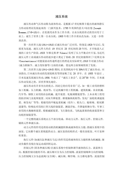
图 1 主起升钢丝绳缠绕示意图
1
液压气动与密封/2017 年第 05 期
1.2 起升液压系统 起升绞车通过安装在其上的液压马达来驱动, 而 液压马达则是通过动力房的液压闭式泵来提供动力, 并且在液压马达上装有速度传感器, 用来采集马达的 转速。液压原理简图如图 2 所示, 电机带动闭式泵以恒 定转速旋转, 闭式泵通过其上的比例阀电流的大小和 方向来改变行程油缸的方向和位置, 从而改变闭式泵 的流量输出大小和方向, 来实现马达的正反转和转动 的快慢。两个起升绞车分别由两组相互独立的闭式泵 控制定量马达调速系统组成, 两个系统元件的各个参 数及性能指标几乎相同。
收稿日期: 2017-03-13 液压系统设计工作。
船上的 360 吨和 1000 吨, 均都可以采用液压驱动的起
1 液压起重机系统分析
1.1 起升机构 示, 两个起升绞车分别经过改向滑轮, 定滑轮组, 动滑 轮组来共同带动起升钩头。 某大型液压起重机的主起升钢丝绳缠绕如图 1 所
1-起升绞车 2-转速传感器 3-人字架改向滑轮 4-臂架改向滑轮 5-测力传感器 6-定向滑轮组 7-动滑轮组 8-起升钩头
文献标志码: A 文章编号: 1008-0813 (2017) 05-0001-05
尹海兵, 吴建奎
Research on Synchronous Control for Large Hydraulic Crane
YIN Hai-bing, WU Jian-kui
(Shanghai Zhenhua Heavy Industries Company Limited, Shanghai 200125, China)
液压起重机轨迹跟踪控制方法的研究

第19卷第2期2021年4月Vol.19No.2Apr.2021中国工程机械学报CHINESE JOURNAL OF CONSTRUCTION MACHINERY液压起重机轨迹跟踪控制方法的研究范学慧1,刘明明1,2(1.江苏建筑职业技术学院智能制造学院,江苏徐州221000;2.江苏大学机械工程学院,江苏镇江212013)摘要:液压起重机对目标轨迹跟踪的正确性,有助于提高其工作效率和工作质量。
为了提高液压起重机对目标轨迹的跟踪正确度,以及跟踪过程的平稳性,设计了一种液压起重机轨迹跟踪控制方法。
首先,通过对液压起重机进行分析,求取了其旋转关节以及执行机构的运动学模型;然后,利用一个低频正弦波,构造了死区补偿装置模型,克服了由控制阀引起的固有死区问题;最后,在液压起重机频率响应函数的基础上,求取了前馈信号的反向稳态增益。
采用本文方法对矩形目标轨迹、圆形目标轨迹以及三角形目标轨迹进行跟踪,以验证其跟踪性能。
通过实验结果显示,与神经网络方法相比,本文方法在对矩形目标轨迹、圆形目标轨迹以及三角形目标轨迹进行跟踪时,最大偏差度分别减小了5.48%、19.76%和17.37%。
由此说明,本文方法能够控制液压起重机对目标轨迹进行准确的跟踪,有助于提高液压起重机的工作可靠度。
关键词:液压起重机;运动学模型;死区补偿装置;频率响应;稳态增益中图分类号:U463文献标志码:A文章编号:1672-5581(2021)02-0148-05Research on trajectory tracking control method ofhydraulic craneFAN Xuehui1,LIU Mingming1,2(1.School of Intelligent Manufacturing,Jiangsu Vocational Institute of Architectural Technology,Xuzhou221000,Jiangsu,China;2.School of Mechanical Engineering,Jiangsu University,Zhenjiang212013,Jiangsu,China)Abstract:The correctness of target trajectory tracking of hydraulic crane is helpful to improve its working efficiency and quality.In order to improve the tracking accuracy of the target trajectory of hydraulic crane and the stability of the tracking process,a trajectory tracking control method of hydraulic crane is designed in this paper.Firstly,through the analysis of hydraulic crane,the kinematics model of its rotating joint and actuator is obtained.Then,using a low-frequency sine wave,a dead-time compensation device model is constructed to overcome the inherent dead-time problem caused by the control valve.Finally,based on the frequency response function of hydraulic crane,the steady-state gain of feed-forward signal is obtained.This method is used to track rectangular,circular and triangular target trajectories to verify their tracking performance.The experimental results show that the maximum deviation of the proposed method is reduced by5.48%,19.76%and17.37%respectively when compared with the neural network method in tracking the trajectories of rectangular,circular and triangular targets.Therefore,this method can control the hydraulic crane to track the target trajectory accurately,and help to improve the working reliability of the hydraulic crane.Key words:hydraulic crane;kinematic model;dead-zone compensation device;frequency response;steady-state gain基金项目:江苏省自然科学基金资助项目(BK20180174)作者简介:范学慧(1980—),女,讲师。
文献翻译-中文-液压汽车起重机的工作原理

译文:液压汽车起重机的工作原理由飓风丹尼引起的暴雨淹没了北卡罗来纳州夏洛特市的许多地方,小糖溪的河水上涨很快,导致一条火车铁轨栈桥倒塌,一辆内燃机列车坠入河道内。
你可以想象一下,一个412,000磅(186880公斤)的机车是不容易打捞的。
当洪水退去过后,紧急救援队紧急救援队伍带来了三个大型液压汽车起重机——1辆500吨,一辆300吨和一辆175吨,用来把火车从河床里面打捞出来,放置回到轨道上面。
液压汽车起重机利用简单的点对点流体力学概念来举起上千磅重的物品。
液压汽车起重机的设计非常简单,但是他能完成一些看似不可能完成的艰巨任务。
在几分钟内,在公路上这些机器可以举起重达几吨的桥梁;在工厂里,这些机器可以举起重型设备;甚至,在建造海滨房屋的时候帮助打桩。
当有些地方比如海洋世界需要将鲸鱼运送到新的目的地的时候,液压汽车起重机同样可以用来举起装鲸鱼的水箱。
当看到这些液压汽车起重机运行的时候,很难相信它将这些如此重的物品相对轻松的移动,因为这些的物品都是上吨级的。
液压汽车起重机有各种不同的提升力。
只需要通过它的名字就可以轻松的知道许多特定的液压汽车起重机的起重能力,例如:一个40吨吊车能吊起40吨(80000磅或36287 kg )。
在这里,你将学习起重机如何利用水力学(液压)举起数千英镑的物体,我们会爬进驾驶室向你展示如何操作这些机器。
这全是关于液压的液压起重机是基于一个简单的概念——通过点对点流体力学概念来进行力的传递。
大多数液压机使用的是一些密度很大大到不可压缩的液体。
油(石油)是最常见的被用来做液压机包括液压起重机的不可压缩的液体。
在一个简单的液压系统里面,当一个活塞推动油(石油),油(石油)就将所有的原动力传送到另一个需要带动的活塞。
在一个简单的液压系统里面,当一个活塞被推动,另一个活塞就会被带动。
液压泵产生的压力推动活塞。
在一个液压系统里面的压力由两种液压泵类型中的一种产生:可变排量泵(变量泵)齿轮泵大多数液压汽车起重机使用的是有一对齿合齿轮向液压油加压的双齿轮泵。
【机械类文献翻译】对移动式遥控装置的智能控制—使用2型模糊理论

附件1:外文资料翻译译文对移动式遥控装置的智能控制——使用2型模糊理论摘要:我们针对单轮移动式遥控装置的动态模型开发出一种追踪控制器,这种追踪控制器是建立在模糊理论的基础上将运动控制器和力矩控制器整合起来的装置。
用计算机模拟来确定追踪控制器的工作情况和它对不同航向的实际用途。
关键词:智能控制、2型模糊理论、移动式遥控装置I. 介绍由于受运动学强制约束,移动遥控装置是非完整的系统。
描述此约束的恒等式不能够明确的反映出遥控装置在局部及整体坐标系中的关系。
因此,包括它们在内的控制问题吸引了去年控制领域的注意力。
不同的方法被用来解决运动控制的问题。
Kanayama等人针对一个非完整的交通工具提出了一个稳定的追踪控制方案,这种方案使用了Lyapunov功能。
Lee等人用还原法和饱和约束来解决追踪控制。
此外,大多数被报道过的设计依赖于智能控制方式如模糊逻辑控制和神经式网络。
然而上述提到的发表中大多数都集中在移动式遥控装置的运动模块,即这些模块是受速度控制的。
而很少有发表关注到不完整的动力系统,即受力和扭矩控制的模块:布洛克。
在2005年12月15日被视为标准并且在2006年3月5日被公认的手稿。
这一著作在某种程度上受到DGEST——一个在Grant 493.05-P下的研究所的支持。
研究者们同样也受到了来自CONACYT——给予他们研究成果的奖学金的支持。
在这篇论文中我展现了一台追踪单轮移动式遥控装置的控制器,这台追踪控制器用了一种控制条件如移动遥控装置的速度达到了有效速度,还用了一种模糊理论控制器如给实际遥控装置提供了必要扭矩。
这篇论文的其余部分的结构如下:第二部分和第三部分对问题作了简洁描述,包括了单轮车移动遥控装置的运动和动力模块和对追踪控制器的介绍。
第四部分用追踪控制器列举了些模拟结果。
第五部分做出了结论。
II. 疑难问题陈述A 移动控制装置这个被看作单轮移动控制器的模型(见图1),它是由两个同轴驱动轮和一个自由前轮组成。
随车起重装置的结构与设计中英文翻译、外文文献翻译

附录 1:外文翻译随车起重装置的结构与设计相对传统的举升机构,该举升机构只采用了液压缸,使液压系统的管路简单,控制方便,液压系统的可靠性高,且安装方便。
上述的分析与计算,为该机构建立了结构与性能等参数间的数学关系。
有关推销与套筒间的摩擦与磨损,套筒导槽角和翻转角度与举升高度的适应性等问题,将有待进一步的分析研究和结构发。
随车起重装置在国外称为随车吊。
本文按国家标准称其为随车起重装置。
一辆安装了随车起重装置的厢式货车在货物运输中, 不仅显示其防雨防尘的专有功能,而且在货物的装卸方面实现了机械化。
1 随车起重装置的发展随车起重装置的发展, 在国外大体上可分为四个时期。
第一代产品产生于本世纪30 年代末, 其特点主要是单缸举升, 而栏板翻转靠手动, 起升质量为500kg 左右, 栏板(又称载物平台) 触地倾角9°~10°。
目前, 这种产品在东南亚、日本仍在使用, 90 年代, 还在美国得到了新的发展。
第二代产品产生于50 年代初的欧洲市场, 在第一代产品的基础上增加了翻转关门油缸。
举升与翻转分别由二个独立油缸实现。
最常见的是四只油缸的型式, 也有双缸的。
起升质量在500 kg 以上, 载物平台触地倾角10°, 翻转动作凭操作者经验控制。
该种产品目前主要用于美洲及东南亚地区。
第三代产品产生于70 年代末的欧洲市场, 是在第二代产品的基础上增加第五只油缸。
这只油缸在液压系统中主要起相对位置的记忆功能, 使载物平台触地、离地的翻转动作不再由操作者控制而由液压系统本身控制, 从而使升降过程相对平稳与安全。
触地倾角一般为8°~10°。
若兼作厢门用, 因平台尺寸增大, 倾角也可能小于8°。
目前该类产品普遍用于欧美地区。
第四代产品产生于90 年代初, 其液压系统及功能原理同第三代产品, 只增加了记忆油缸的尺寸, 使记忆动作的范围进一步增大。
它不同于第三代产品的关键在于其载物平台增加特殊结构, 由一体改为两体活动联接, 使平台触地后不仅能自动翻转, 而且有一个下沉的动作, 使触地倾角达到6°, 甚至在6以下。
【机械类文献翻译】液压系统设计
液压系统液压传动和气压传动称为流体传动,是根据17世纪帕斯卡提出的液体静压力传动原理而发展起来的一门新兴技术,1795年英国约瑟夫•布拉曼(Joseph Braman,1749-1814),在伦敦用水作为工作介质,以水压机的形式将其应用于工业上,诞生了世界上第一台水压机。
1905年将工作介质水改为油,又进一步得到改善。
第一次世界大战(1914-1918)后液压传动广泛应用,特别是1920年以后,发展更为迅速。
液压元件大约在19世纪末20世纪初的20年间,才开始进入正规的工业生产阶段。
1925年维克斯(F.Vikers)发明了压力平衡式叶片泵,为近代液压元件工业或液压传动的逐步建立奠定了基础。
20世纪初康斯坦丁•尼斯克(G •Constantimsco)对能量波动传递所进行的理论及实际研究;1910年对液力传动(液力联轴节、液力变矩器等)方面的贡献,使这两方面领域得到了发展。
第二次世界大战(1941-1945)期间,在美国机床中有30%应用了液压传动。
应该指出,日本液压传动的发展较欧美等国家晚了近20多年。
在1955年前后,日本迅速发展液压传动,1956年成立了“液压工业会”。
近20~30年间,日本液压传动发展之快,居世界领先地位。
液压传动有许多突出的优点,因此它的应用非常广泛,如一般工业用的塑料加工机械、压力机械、机床等;行走机械中的工程机械、建筑机械、农业机械、汽车等;钢铁工业用的冶金机械、提升装置、轧辊调整装置等;土木水利工程用的防洪闸门及堤坝装置、河床升降装置、桥梁操纵机构等;发电厂涡轮机调速装置、核发电厂等等;船舶用的甲板起重机械(绞车)、船头门、舱壁阀、船尾推进器等;特殊技术用的巨型天线控制装置、测量浮标、升降旋转舞台等;军事工业用的火炮操纵装置、船舶减摇装置、飞行器仿真、飞机起落架的收放装置和方向舵控制装置等。
一个完整的液压系统由五个部分组成,即动力元件、执行元件、控制元件、辅助元件和液压油。
液压系统外文文献翻译中英文

外文文献翻译(含:英文原文及中文译文)英文原文Hydraulic systemW Arnold1 IntroductionThe hydraulic station is called a hydraulic pump station and is an independent hydraulic device. It is step by step to supply oil. And control the direction of hydraulic oil flow, pressure and flow, suitable for the host and hydraulic equipment can be separated on the various hydraulic machinery.After the purchase, the user only needs to connect the hydraulic station and the actuator (hydraulic or oil motor) on the mainframe with different tubings. The hydraulic machine can realize various specified actions and working cycles.The hydraulic station is a combination of manifolds, pump units or valve assemblies, electrical boxes, and tank electrical boxes. Each part function is:The pump unit is equipped with a motor and an oil pump, which is the power source of the hydraulic station and can convert mechanical energy into hydraulic oil pressure energy.V alve combination - its plate valve is mounted on the vertical plate, and the rear plate is connected with the same function as the manifold.Oil manifolds - assembled from hydraulic valves and channel bodies. It regulates hydraulic oil pressure, direction and flow.Box--a semi-closed container for plate welding. It is also equipped with an oil screen, an air filter, etc., which is used for cooling and filtering of oil and oil.Electrical box - divided into two types: one is to set the external lead terminal board; one is equipped with a full set of control appliances.The working principle of the hydraulic station: The motor drives the oil pump to rotate, then the pump sucks oil from the oil tank and supplies oil, converts the mechanical energy into hydraulic pressure energy, and the hydraulic oil passes through the manifold (or valve assembly) to adjust the direction, pressure and flow and then passes through the external tube. The way to the hydraulic cylinder or oil motor in the hydraulic machinery, so as to control the direction of the hydraulic motor, the strength of the speed and speed, to promote all kinds of hydraulic machinery to do work.(1) Development history of hydraulic pressureThe development history of hydraulics (including hydraulic power, the same below), pneumatics, and seals industry in China can be roughly divided into three stages, namely: the starting stage in the early 1950s to the early 60s; and the professional in the 60s and 70s. The growth stage of the production system; the 80-90's is a stage of rapid development. Among them, the hydraulic industry began in the early 1950s with thedevelopment of hydraulic machines such as Grinding Machines, broaching machines, and profiling lathes, which were produced by the machine tool industry. The hydraulic components were produced by the hydraulic workshop in the machine tool factory, and were produced for self use. After entering the 1960s, the application of hydraulic technology was gradually promoted from the machine tool to the agricultural machinery and engineering machinery. The original hydraulic workshop attached to the main engine plant was independent and became a professional manufacturer of hydraulic components. In the late 1960s and early 1970s, with the continuous development of mechanization of production, particularly in the provision of highly efficient and automated equipment for the second automobile manufacturing plant, the hydraulic component manufacturing industry witnessed rapid development. The batch of small and medium-sized enterprises also began to become specialized manufacturers of hydraulic parts. In 1968, the annual output of hydraulic components in China was close to 200,000 pieces. In 1973, in the fields of machine tools, agricultural machinery, construction machinery and other industries, the professional factory for the production of hydraulic parts has grown to over 100, and its annual output exceeds 1 million pieces. Such an independent hydraulic component manufacturing industry has taken shape. At this time, the hydraulic product has evolved from the original imitation Su product intoa combination of imported technology and self-designed products. The pressure has been developed towards medium and high pressures, and electro-hydraulic servo valves and systems have been developed. The application of hydraulics has been further expanded. The pneumatic industry started a few years later than hydraulics, and it was only in 1967 that it began to establish a professional pneumatic components factory. Pneumatic components began to be manufactured and sold as commodities. Its sealing industry including rubber seals, flexible graphite seals, and mechanical seals started from the production of common O-rings, oil seals, and other extruded rubber seals and asbestos seal products in the early 1950s. In the early 1960s, it began to develop and produce flexible products. Graphite seals and mechanical seals and other products. In the 1970s, a batch of batches of professional production plants began to be established one after another in the systems of the former Ministry of Combustion, the Ministry of Agriculture, and the Ministry of Agricultural Machinery, formally forming the industry, which laid the foundation for the development of the seal industry.In the 1980s, under the guidance of the national policy of reform and opening up, with the continuous development of the machinery industry, the contradiction between the basic components lags behind the host computer has become increasingly prominent and caused the attention of all relevant departments. To this end, the former Ministry of Machinesestablished the General Infrastructure Industry Bureau in 1982, and unified the original pneumatic, hydraulic, and seal specialties that were scattered in the industries of machine tools, agricultural machinery, and construction machinery, etc. The management of a piece of office, so that the industry in the planning, investment, the introduction of technology and scientific research and development and other aspects of the basic parts of the bureau's guidance and support. This has entered a period of rapid development, it has introduced more than 60 foreign advanced technology, of which more than 40 hydraulic, pneumatic 7, after digestion and absorption and technological transformation, are now mass production, and has become the industry's leading products . In recent years, the industry has intensified its technological transformation. From 1991 to 1998, the total investment of national, local, and corporate self-raised funds totaled about 2 billion yuan, of which more than 1.6 billion were hydraulic. After continuous technological transformation and technological breakthroughs, the technical level of a group of major enterprises has been further improved, and technological equipment has also been greatly improved, laying a good foundation for forming a high starting point, specialization, and mass production. In recent years, under the guidance of the principle of common development of multiple ownership systems in the country, various small and medium-sized enterprises with different ownership have rapidly emerged and haveshown great vitality. With the further opening up of the country, foreign-funded enterprises have developed rapidly, which plays an important role in raising industry standards and expanding exports. So far China has established joint ventures with famous manufacturers in the United States, Germany, Japan and other countries or directly established piston pumps/motors, planetary speed reducers, hydraulic control valves, steering gears, hydraulic systems, hydrostatic transmissions, and hydraulic components. The company has more than 50 manufacturing enterprises such as castings, pneumatic control valves, cylinders, gas processing triplets, rubber seals, and mechanical seals, and has attracted more than 200 million U.S. dollars in foreign capital.(2) Current statusBasic profileAfter more than 40 years of hard work, China's hydraulics, pneumatics and seals industry has formed a complete industrial system with a certain level of production capacity and technical level. According to the statistics of the third n ational industrial census in 1995, China’s state-owned, privately-owned, cooperative, village-run, individual, and “funded enterprises” have annual sales income of more than 1 million yuan in hydraulic, pneumatic, and seal industrial townships and above. There are a total of more than 1,300 companies, including about 700 hydraulics, and about 300 pneumatic and sealing parts. According to thestatistics of the international industry in 1996, the total output value of the hydraulic industry in China was about 2.448 billion yuan, accounting for the 6th in the world; the total output value of the pneumatic industry was about 419 million yuan, accounting for the world’s10 people.2. Current supply and demand profileWith the introduction of technology, independent development and technological transformation, the technical level of the first batch of high-pressure plunger pumps, vane pumps, gear pumps, general hydraulic valves, oil cylinders, oil-free pneumatic components and various types of seals has become remarkable. Improve, and can be stable mass production, provide guarantees for all types of host to improve product quality. In addition, certain achievements have also been made in the aspects of CAD, pollution control, and proportional servo technology for hydraulic pneumatic components and systems, and have been used for production. So far, the hydraulic, pneumatic and seal products have a total of about 3,000 varieties and more than 23,000 specifications. Among them, there are about 1,200 types of hydraulic pressure, more than 10,000 specifications (including 60 types of hydrodynamic products, 500 specifications); about 1350 types of pneumatic, more than 8,000 specifications; there are also 350 types of rubber seals, more than 5000 The specifications are now basically able to adapt to the general needs ofvarious types of mainframe products. The matching rate for major equipment sets can reach more than 60%, and a small amount of exports has started.In 1998, the domestic production of hydraulic components was 4.8 million pieces, with sales of about 2.8 billion yuan (of which mechanical systems accounted for 70%); output of pneumatic components was 3.6 million pieces, and sales were about 550 million yuan (including mechanical systems accounting for about 60%) The production of seals is about 800 million pieces, and the sales volume is about 1 billion yuan (including about 50% of mechanical systems). According to the statistics of the annual report of the China Hydraulic and Pneumatic Sealing Industry Association in 1998, the production and sales rate of hydraulic products was 97.5% (101% of hydraulic power), 95.9% of air pressure, and 98.7% of seal. This fully reflects the basic convergence of production and sales.Although China's hydraulic, pneumatic and sealing industries have made great progress, there are still many gaps compared with the development needs of the mainframe and the world's advanced level, which are mainly reflected in the variety, performance and reliability of products. . Take hydraulic products as an example, the product varieties are only 1/3 of the foreign country, and the life expectancy is 1/2 of that of foreign countries. In order to meet the needs of key hosts, imported hosts, and majortechnical equipment, China has a large number of imported hydraulic, pneumatic, and sealing products every year. According to customs statistics and relevant data analysis, in 1998, the import volume of hydraulic, pneumatic and seal products was about 200 million U.S. dollars, of which the hydraulic pressure was about 140 million U.S. dollars, the pneumatics were 30 million U.S. dollars, and the seal was about 0.3 billion U.S. dollars. The year is slightly lower. In terms of amount, the current domestic market share of imported products is about 30%. In 1998, the total demand for hydraulic parts in the domestic market was about 6 million pieces, and the total sales volume was 4 billion yuan; the total demand for pneumatic parts was about 5 million pieces, and the total sales volume was over 700 million yuan; the total demand for seals was about 1.1 billion yuan. Pieces, total sales of about 1.3 billion yuan. (3) Future developments1. The main factors affecting development(1) The company's product development capability is not strong, and the level and speed of technology development can not fully meet the current needs for advanced mainframe products, major technical equipment and imported equipment and maintenance;(2) Many companies have lagged behind in manufacturing process, equipment level and management level, and their sense of quality is not strong, resulting in low level of product performance, unstable quality,poor reliability, and insufficiency of service, and lack of user satisfaction. And trusted branded products;(3) The degree of professional specialization in the industry is low, the power is scattered, the duplication of the low level is serious, the product convergence between the region and the enterprise leads to blind competition, and the prices are reduced each other, thus the efficiency of the enterprise is reduced, the funds are lacking, and the turnover is difficult. Insufficient investment in development and technological transformation has severely restricted the overall level of the industry and its competitive strength.(4) When the degree of internationalization of the domestic market is increasing, foreign companies have gradually entered the Chinese market to participate in competition, coupled with the rise of domestic private, cooperative, foreign-funded, and individual enterprises, resulting in increasing impact on state-owned enterprises. .2. Development trendWith the continuous deepening of the socialist market economy, the relationship between supply and demand in the hydraulic, pneumatic and sealed products has undergone major changes. The seller market characterized by “shortage” has basically become a buyer’s market characterized by “structured surplus”. Replaced by. From the perspective of overall capacity, it is already in a trend of oversupply, and in particular,general low-grade hydraulic, pneumatic and seals are generally oversupply; and like high-tech products with high technological content and high value and high value-added products that are urgently needed by the host, Can not meet the needs of the market, can only rely on imports. After China's entry into the WTO, its impact may be greater. Therefore, during the “10th Five-Y ear Plan” period, the growth of the industry’s output value must not only rely on the growth of quantity. Instead, it should focus on the structural contradiction of the industry and intensify efforts to adjust the industrial structure and product structure. It should be based on the improvement of quality. Product technology upgrades in order to adapt to and stimulate market demand, and seek greater development.2. Hydraulic application on power slide(1) Introduction of Power Sliding TableUsing the binding force curve diagram and the state space analysis method to analyze and study the sliding effect and the smoothness of the sliding table of the combined machine tool, the dynamics of the hydraulic drive system of the sliding table—the self-regulating back pressure regulating system are established. mathematical model. Through the digital simulation system of the computer, the causes and main influencing factors of the slide impact and the motion instability are analyzed. What kind of conclusions can be drawn from those, if we canreasonably design the structural dimensions of hydraulic cylinders and self-regulating back pressure regulators ——The symbols used in the text are as follows:s 1 - flow source, that is, the flow rate of the governor valve outlet;S el —— sliding friction of the sliding table;R - the equivalent viscous friction coefficient of the slide;I 1 - quality of slides and cylinders;12 - self-adjusting back pressure valve core quality;C 1, c 2 - liquid volume without cylinder chamber and rod chamber;C 2 - Self-adjusting back pressure valve spring compliance;R 1, R2 - Self-adjusting back pressure valve damping orifice fluid resistance;R 9 - Self-adjusting back pressure valve valve fluid resistance;S e2——initial pre-tightening force of self-adjusting back pressure valve spring;I 4, I5 - Equivalent liquid sense of the pipeline;C 5, C 6 - equivalent liquid capacity of the pipeline;R 5, R7 - Equivalent liquid resistance of the pipeline;V 3, V4 - cylinder rodless cavity and rod cavity volume;P 3, P4—pressure of the rodless cavity and rod cavity of the cylinder;F - the slide bears the load;V - speed of slide motion;In this paper, the power bond diagram and the state space splitting method are used to establish the system's motion mathematical model, and the dynamic characteristics of the slide table can be significantly improved.In the normal operation of the combined machine tool, the magnitude of the speed of the slide, its direction and the load changes it undergoes will affect its performance in varying degrees. Especially in the process of work-in-process, the unsteady movement caused by the advancing of the load on the slide table and the cyclical change of the load will affect the surface quality of the workpiece to be machined. In severe cases, the tool will break. According to the requirements of the Dalian Machine Tool Plant, the author used the binding force curve diagram and the state space analysis method to establish a dynamic mathematical model of a self-adjusting back pressure and speed adjustment system for the new hydraulic drive system of the combined machine tool slide. In order to improve the dynamic characteristics of the sliding table, it is necessary to analyze the causes and main influencing factors of the impetus and movement of the sliding table. However, it must pass the computer's digital simulation and the final results obtained from the research.(2) Dynamic Mathematical ModelThe working principle diagram of the self-adjusting back pressure speedregulation system of the combined machine tool slide hydraulic drive system is shown in the figure. This system is used to complete the work-cycle-stop-rewind. When the sliding table is working, the three-position four-way reversing valve is in the illustrated position. The oil supply pressure of the oil pump will remain approximately constant under the effective action of the overflow valve, and the oil flow passes through the reversing valve and adjusts the speed. The valve enters the rodless chamber of the cylinder to push the slide forward. At the same time, the pressurized oil discharged from the rod chamber of the cylinder will flow back to the tank through the self-regulating back pressure valve and the reversing valve. During this process, there was no change in the operating status of both the one-way valve and the relief valve. The complex and nonlinear system of the hydraulic drive system of the self-adjusting back pressure governor system is a kind of self-adjusting back-pressure governor system. To facilitate the study of its dynamic characteristics, a simple and reasonable dynamic mathematical model that only considers the main influencing factors is established. Especially important [1][2]. From the theoretical analysis and the experimental study, we can see that the system process time is much longer than the process time of the speed control valve. When the effective pressure bearing area of the rodless cavity of the fuel tank is large, the flow rate at the outlet of the speed control valve is instantaneous. The overshoot is reflected in thesmall change in speed of the slide motion [2]. In order to further broaden and deeply study the dynamic characteristics of the system so that the research work can be effectively performed on a miniature computer, this article will further simplify the original model [2], assuming that the speed control valve is output during the entire system pass. When the flow is constant, this is considered to be the source of the flow. The schematic diagram of the dynamic model structure of this system is shown in Fig. 2. It consists of a cylinder, a sliding table, a self-adjusting back pressure valve, and a connecting pipe.The power bond graph is a power flow graph. It is based on the transmission mode of the system energy, based on the actual structure, and uses the centralized parameters to represent the role of the subsystems abstractly as a resistive element R, a perceptual element I, and a capacitive element. Three kinds of role of C. Using this method, the physical concept of modeling is clear, and combined with the state-space analysis method, the linear system can be described and analyzed more accurately. This method is an effective method to study the dynamic characteristics of complex nonlinear systems in the time domain. According to the main characteristics of each component of the self-adjusting back pressure control system and the modeling rules [1], the power bond diagram of the system is obtained. The upper half of each key in the figure represents the power flow. The two variables that makeup the power are the force variables (oil pressure P and force F) and the flow variables (flow q and velocity v). The O node indicates that the system is connected in parallel, and the force variables on each key are equal and the sum of the flow variables is zero; 1 The nodes represent the series connection in the system, the flow variables on each key are equal and the sum of the force variables is Zero. TF denotes a transformer between different energy forms. The TF subscripted letter represents the conversion ratio of the flow variable or the force variable. The short bar on the key indicates the causal relationship between the two variables on the key. The full arrow indicates the control relationship. There are integral or differential relationships between the force and flow variables of the capacitive and perceptual elements in the three types of action elements. Therefore, a complex nonlinear equation of state with nine state variables can be derived from Fig. 3 . In this paper, the research on the dynamic characteristics of the sliding table starts from the two aspects of the slide's hedging and the smoothness of the motion. The fourth-order fixed-length Runge-Kutta is used for digital simulation on the IBM-PC microcomputer.(3) Slide advanceThe swaying phenomenon of the slide table is caused by the sudden disappearance of the load acting on the slide table (such as drilling work conditions). In this process, the table load F, the moving speed V, and thepressure in the two chambers of the cylinder P3 and P4 can be seen from the simulation results in Fig. 4. When the sliding table moves at a uniform speed under the load, the oil pressure in the rodless cavity of the oil cylinder is high, and a large amount of energy is accumulated in the oil. When the load suddenly disappears, the oil pressure of the cavity is rapidly reduced, and the oil is rapidly reduced. When the high-pressure state is transferred to the low-pressure state, a lot of energy is released to the system, resulting in a high-speed forward impact of the slide. However, the front slide of the sliding table causes the pressure in the rod cavity of the oil cylinder to cause the back pressure to rise, thereby consuming part of the energy in the system, which has a certain effect on the kicking of the slide table. We should see that in the studied system, the inlet pressure of the self-adjusting back pressure valve is subject to the comprehensive effect of the two-chamber oil pressure of the oil cylinder. When the load suddenly disappears, the pressure of the self-adjusting back pressure valve rapidly rises and stably exceeds the initial back pressure value. It can be seen from the figure that self-adjusting back pressure in the speed control system when the load disappears, the back pressure of the cylinder rises more than the traditional speed control system, so the oil in the rod cavity of the cylinder absorbs more energy, resulting in the amount of forward momentum of the slide It will be about 20% smaller than traditionalspeed control systems. It can be seen from this that the use of self-adjusting back-gear speed control system as a drive system slider has good characteristics in suppressing the forward punch, in which the self-adjusting back pressure valve plays a very large role.(4) The smoothness of the slideWhen the load acting on the slide changes periodically (such as in the case of milling), the speed of the slide will have to fluctuate. In order to ensure the processing quality requirements, it must reduce its speed fluctuation range as much as possible. From the perspective of the convenience of the discussion of the problem, assume that the load changes according to a sine wave law, and the resulting digital simulation results are shown in Figure 5. From this we can see that this system has the same variation rules and very close numerical values as the conventional speed control system. The reason is that when the change of the load is not large, the pressure in the two chambers of the fuel tank will not have a large change, which will eventually lead to the self-regulating back pressure valve not showing its effect clearly.(5) Improvement measuresThe results of the research show that the dynamic performance of a sliding table with self-regulating back pressure control system as a drive system is better than that of a traditional speed control system. To reduce the amount of kick in the slide, it is necessary to rapidly increase the backpressure of the rod cavity when the load disappears. To increase the smoothness of the sliding table, it is necessary to increase the rigidity of the system. The main measure is to reduce the volume of oil. From the system structure, it is known that the cylinder has a large volume between the rod cavity and the oil discharge pipe, as shown in Fig. 6a. Its existence in terms of delay and attenuation of the self-regulating back pressure valve function, on the other hand, also reduces the rigidity of the system, it will limit the further improvement of the propulsion characteristics and the smoothness of the motion. Thus, improving the dynamic characteristics of the sliding table can be handled by two methods: changing the cylinder volume or changing the size of the self-regulating back pressure valve. Through the simulation calculation of the structural parameters of the system and the comparison of the results, it can be concluded that the ratio of the volume V4 between the rod cavity and the oil discharge pipe to the volume V3 between the rodless cavity and the oil inlet pipe is changed from 5.5 to 5.5. At 1 oclock, as shown in the figure, the diameter of the bottom end of the self-adjusting back pressure valve is increased from the original 10mm to 13mm, and the length of the damper triangle groove is reduced from the original lmm to 0.7mm, which will enable the front of the slide table. The impulse is reduced by 30%, the transition time is obviously shortened, and the smoothness of the slide motion will also be greatly improved.中文译文液压系统W Arnold1. 绪论液压站称液压泵站,是独立的液压装置。
液压同步回路在起重机械中的应用

液压同步回路在起重机械中的应用彭飞; 郭敬甫; 刘新生; 杨晓辉【期刊名称】《《起重运输机械》》【年(卷),期】2019(000)013【总页数】6页(P135-140)【关键词】起重机械; 液压; 同步系统【作者】彭飞; 郭敬甫; 刘新生; 杨晓辉【作者单位】纽科伦(新乡)起重机有限公司新乡 453000【正文语种】中文【中图分类】TH2180 引言同步运动是指两个或者两个以上部件具有相同的运动状态,最主要的同步标志是位移和速度相同。
随着科学技术的发展,自动化水平日益提高,液压同步技术以其功率密度大,动作平稳等优点越来越多地应用到各种起重设备中,液压同步技术已成为现代化建设中不可或缺的一项技术。
1 液压同步回路的组成液压同步回路与其他液压系统组成类似,都由液压源、执行元件、管路附件等构成。
液压同步回路可以看做流量调节回路的一种特殊情况,同步回路的参数匹配、元件选型对回路同步精度[1]有较大的影响。
2 常用液压同步回路常用液压同步技术主要有机械限制强制同步、节流调速同步、同步阀同步、液压同步马达同步、液压缸串联同步、比例阀调节同步和数字阀调节同步。
2.1 机械限制强制同步如图1所示机械限制强制同步回路是通过机械结构连接运动部件,达到同步运动的目的。
该同步回路结构简单,所用阀件少,成本低,但要求相应的机械结构有较强的刚度,相对运动的部件之间间隙要合理,一般机械限制强制同步回路同步精度约为5%,机械配合精度对同步精度的影响较大,相对运动部件的配合精度越高,系统的同步精度也越高。
适用于同步精度要求不高、液压缸相距近、机械连接刚度较强的场合。
图1 机械限制强制同步回路原理图公司近期研发的自攀爬风电维修起重机项目中应用了机械限制强制同步回路。
如图2所示外筒与内筒之间有可调滑块,外筒与内筒配合紧密并且可以相对滑动,平台固定在外筒上,液压缸活塞杆端通过销轴连接在外筒两侧,液压缸尾部通过销轴连接在内筒两侧,液压缸伸缩带动内外筒相对运动进而带动平台上下运动,外筒与两个液压缸销轴耳板焊接在一起形成刚性连接,强制两个液压缸同步运动。
机械类英语论文及翻译
机械类英语论文及翻译Mechanical design involves the n of machines。
which are composed of mechanisms and other components that can transform and transmit ___ machines include engines。
turbines。
vehicles。
hoists。
printing presses。
washing machines。
and ___ and methods of design that apply to machines also apply to ___。
the term "mechanical design" is used in a broader sense than "machine design" to include their design.When ___。
___ to take into account。
The n and structural aspects of the device。
as well as the ___。
___ apply not only to machines but also to other mechanical devices。
such as switches。
cams。
valves。
vessels。
and mixers.Mechanical design is a critical field in ___ disciplines。
It plays an essential role in the ___ the success of a mechanical design project。
it is essential to follow a set of rules for design。
电动卷扬机的控制——机械专业毕业设计论文外文翻译(中英文翻译、外文文献翻译)

电动卷扬机的控制——机械专业毕业设计论文外文翻译(中英文翻译、外文文献翻译)电动卷扬机的控制——机械专业毕业设计论文外文翻译(中英文翻译、外文文献翻译)英文原文Electrical Winch Controlsby Tom YoungThe form of motor control we all know best is the simple manual station with up and down pushbuttons. While these stations may still be the perfect choice for certain applications,a dizzying array of more sophisticatedcontrols is also available. This article addresses the basic electrical requirements of the motors and user interface issues you will need to address before specifying,building or buying winch controls.To begin with,the manual control stations should be of the hold-to-run type,so that if you take your finger off of the button the winch stops. Additionally,every control station needs an emergency stop (E-stop) that kills all power to the winch,not just the control circuit. Think aboutit―if the winch isn’t stopping when it should,you really need a failsafeway to kill the line power. It’s also a great idea to have a key operated switch on control stations,especially where access to the stations is not controlled.Safe operation by authorized personnel must be considered whendesigning even the simplest manual controls.Controlling Fixed Speed MotorsThe actual controlling device for a fixed speed winch is a three phase reversing starter. The motor is reversed by simply switching the phase sequence from ABC to CBA. This is accomplished by two three-pole contactors,interlocked,so they can’t both be closed at the same time.The NEC requires both overload and short circuit protection. To protect the motor from overheating due to mechanical overloads a thermal overload relay is built into the starter. This has bi-metallic strips that match the heating pattern of the motor and trips contacts when they overheat. Alternatively,a thermistor can be mounted in the motor winding to monitor the motor temperature. Short circuit protection is generally provided by fuses rated for use with motors.A separate line contactor should be provided ahead of the reversing contactor for redundancy. This contactor is controlled by the safety circuits: E-stop and overtravel limits.This brings us to limit switches. When you get to the normal end of travel limit the winch stops and you can only move it in the opposite direction (away from the limit). There also needs to be an overtravel limit in case,due to an electrical or mechanical problem,the winch runs pastthe normal limit. If you hit an overtravel limit the line contactor opens so there is no way to drive off ofthe limits. If this occurs,a competent technician needs to fix the problem that resulted in hitting the overtravel limit. Then,you can override the overtravels using the spring return toggle switchinside the starter―as opposed to using jumpers or hand shooting the contactors.Variable Speed RequirementsOf course,the simple fixed speed starter gets replaced with a variable speed drive. Here’s where things start to get interesting! At the very least you need to add a speed pot to the control station. A joystick is a better operator interface,as it gives you a moreintuitive control ofthe moving piece.Unfortunately,you can’t just order any old variable speed drive from your local supplier and expect it to raise and lower equipment safely and reliably over kids on stage. Most variable speed drives won’t,as theyaren’t designed for lifting. The drive needs to be set up so that torque is developed at the motor before the brake is released,and (when stopping)the brake is set before torque is taken away.For many years DC motors and drives provided a popular solution as they allowed for good torque at all speeds. The large DC motors required for most winches are expensive,costing many times what a comparable ACmotor costs. However,the early AC drives were not very useful,as theyhad a very limited speed range and produced low torque at low speeds. More recently,as the AC drives improved,the low cost and plentiful availability of AC motors resulted in a transition to AC drives.There are two families of variable speed AC drives. Variable frequency inverters are well known and readily available. These drives convert AC to DC,then convert itback to AC with a different frequency. If the drive produces 30 Hz,a normal 60 Hz motor will run at half speed. In theory this isgreat,but in reality there are a couple of problems. First,a typical 60Hz motorgets confused at a line frequency below 2 or 3 Hz,and starts to cog (jerkand sputter),or just stops. This limits you to a speed range of as low as 20:1―hardly suitable for subt le effects on stage! Second,many lowercost inverters are also incapable of providing full torque at low speeds. Employing such drives can result in jerky moves,or a complete failureto lift the piece―exactly what you don’t want to see when you are tryingto start smoothly lifting a scenic element. Some of the newer inverters are closed loop (obtain feedback from the motor to provide more accurate speed control) and will work quite well.The other family of AC drives is flux vector drives. These units require an encoder mounted on the motor shaft allowing the driv。
汽车起重机液压系统中英文对照外文翻译文献

汽车起重机液压系统中英文对照外文翻译文献(文档含英文原文和中文翻译)翻译:汽车式起重机液压系统—技术现状与发展趋势一、行业背景(一)国外工程汽车起重机的发展趋势近20年世界工程起重机行业发生了很大变化。
RT(越野轮胎起重机)和AT(全地面起重机)产品的迅速发展,打破了原有产品与市场格局,在经济发展及市场激烈竞争冲击下,导致世界市场进一步趋向一体化。
为与RT和AT产品抗衡,汽车起重机新技术、新产品也在不断发展。
近年来汽车起重机在英、美等国市场的复兴,使人们对汽车起重机产生新的认识。
几年前某些工业界人士曾预测,RT 和AT产品的兴起将导致汽车起重机的衰退。
日本汽车起重机在世界各地日益流行,以及最近格鲁夫、特雷克斯、林克.贝尔特、德马泰克等公司汽车起重机的产品进展,已向上述观念提出挑战。
随着工程起重机各机种间技术的相互渗透与竞争,汽车起重机会在世界市场中继续占有一席之地。
国外工程起重机从整体情况分析,领先国内10~20年(不同类型产品有所不同)。
随着国外经济发展速度趋于平稳,工程起重机向智能、高性能、灵活、适应性强、多功能方向发展。
25t以下基本上不生产,产品向高附加值、大吨位发展,住友建机、多田野和加藤公司曾于1989年相继推出360t汽车起重机。
住友建机在90年代开发出80t~250t共4种AT产品。
多田野也在90年代相继推出100t~550t共6种特大型AT产品。
加藤公司则研制成NK5000型500t汽车起重机。
行业配套也与国内有所不同:1、下车主要是300kW以上柴油大功率发动机,与之配套的液力变矩器和自动换档变速箱、12吨级驱动转向桥及越野轮胎。
2、上车:高强度材料、大扭矩的起升机构、回转机构、回转支承。
3、液压系统:变量泵、变量马达、电磁换向先导阀及主阀、平衡阀、悬挂系统阀、液压锁、液压缸及管路标准配套件。
4、智能控制系统:力限器显示控制、记忆通讯及单缸顺序伸缩自动控制。
(二)国内工程汽车起重机的发展趋势国内工程机械产品近十年来随着技术的引进、消化、吸收,有了长足的进步,产品性能、可靠性、外观都有较大幅度的提高,但同国外工程机械比较来看,还存在较大差距。
【机械类文献翻译】自动化立体仓库的控制方法
自动化立体仓库的控制方法【1】BJ0806(04)曹靖斯摘要本文的目的是自动化立体仓库系统管理控制算法的研究。
想往常一样,控制算法的实现需要三个基本步骤:开发一个可靠的模型;设计一系列的优化标准程序;验证这些控制程序。
至于建模,在新的层次上执行实时优化,从而简化了低级别的控制结构,即优化系统,提高整体的性能。
在此背景下,讨论整个仓库的详细建模,和这种模型所使用的着色和网格框架。
以此对照,我们提出了两种控制算法,推导简化货架连续位置的假设,堆垛机(仓库通道内的移动的优化操作)和货叉在货架间提取或储存的一个直线操作。
为了评估所提出的控制性能和算法,我们定义了三种不同的考核指数。
相对于执行一个测试动作,考虑通信延迟并进一步验证算法计算用时。
最后,所提出的结构和控制算法应用到真正的工厂中。
1.介绍在过去的十五年间,在寻找最佳的规划与仓库管理系统上有了巨大的成就。
这些问题变得越来越具有挑战性,随着现代计算机技术的发展,可以实现复杂动作的全自动化控制。
规划包括了高级的决策,比如分配货物的存储位置(随机,分类,聚集相关产品的方法)(VandenBerg, 1999)或者设计仓库系统本体。
控制的最优化和调度储存以及检测请求组成了所谓的调度配送控制。
我们知道通常一个仓库包含多个通道,它们每一个都由堆垛机、货叉、提取/存储位置和输入输出缓冲区域来服务运行的。
(参见图1的例子是一个真正的布局)。
每一侧各有一个货架通道,包括横向和纵向。
此外,每一个通道由一个堆垛机服务并可以竖直和水平同时控制执行以下操作:1.提取存储在输入缓冲区走道上的库存单元;2.该单元被指定存储到某个货架位置;3.该货架位置被申请称为R;4.将货物送达R点并存储;5.堆垛机回到输入输出点。
这些动作被称为存储系统的内容,一个多命令的机器循环。
(Graves, Hausman,& Shieh, 1977; Bozer & White, 1984; Han,McGinnis, Shieh, & White, 1987; Lee, de Souza, &Ong, 1996).作为堆垛机,它沿着一个单维的路径在正交的轨道上运行,并进行提取(从主要的输入缓冲区,输出位置通道和选取存储的输出位置)和存储动作(进入的主要输出缓冲区,输入位置信道,选取/存储输入位置)。
随车液压起重机的控制——外文文献翻译、中英文翻译

随车液压起重机的控制——外文文献翻译、中英文翻译附录A0psi/600 psi了。
无论如何,这样的话,提供的电量必须高于有效电量,这些额外的电量就被白白的浪费了2.3 控制系统不同的控制方法目前主要用电液比例控制阀来控制液压阀的运动。
然而对控制筒有不同的控制方法。
电液比例控制阀对阀的关/开,公共汽车系统,电源的智能激励,泵的调节方案控制精度都较高。
必须对这种系统的优缺点进行分析,找出合理的方案。
2.4 近期方案即使这种十分新的系统最佳外形的布局已经得以证明是可行的,但是起重机制造商和配件商还不能立刻就接受这种技术。
这是一个渐进的过程,所以提出了一种临时解决的方案。
这种方案是由微型计算机和升缩机构组成。
这种离合阀可使这种更加高效稳定的执行控制机构得以实现。
微型计算机可以对阀进行柔性控制。
可以把这些变量编入软件。
这样就消除了制造商许许多多不同的变量问题。
起重机制造厂家可以根据产品功能选择不同型号的液压阀。
配件商也将不得不生产这种型号的阀,这样不仅降低了制造成本,而且使起重机的性能得到提高。
2.5 更高效方案的分析这种分析依赖于不同布局结果,液压泵控制的区域决定将要用的控制方法,再依次对这个区域进行分析。
不同的区域将用不同的方法探讨,用不同的刀具位置控制。
3. 实验设备本文的中心是研究发展中的经济型机械控制方案的可实现问题,更多重点是先进的实验结果。
实验结果由两种方法获得。
第一种是通过研究单自由起重机实验台获得,第二种是通过研究一台由丹麦一家起重机厂送给英国的一所军校的起重机获得。
如图1所示图1系统实验台左:单自由度起重机模型右:随车起重机实物虽然目前这种升缩分离机构在生产商中没有被普遍接受,但是两分离阀将会被逐渐取代。
如图2所示是一种幅度-脉冲变换液压缸,它是通过数字信息处理器/奔腾双信息处理器运行程序来控制液压阀的。
由数字信号处理器运行控制代码,奔腾处理器来判断并提供图形用户界面。
4. 当前工作4.1 直线轴流控法当今市场常见的直线流控器都需要压力补偿。
【机械类文献翻译】应用于电气系统的可编程序控制器

外文资料翻译
学生姓名:
所在院系:
Байду номын сангаас
所学专业:
导师姓名:
完成时间:
Programmable designed for electro-pneumatic systems controller Abstract
This project deals with the study of electro-pneumatic systems and The programmable controller that provides an effective and easy way to Control the sequence of the pneumatic actuators movement and the states of pneumatic system. The project of a specific controller for pneumatic applications join the study of automation design and the control processing of pneumatic systems with the electronic design based on microcontrollers to implement the resources of the controller.
1.Introduction
The automation systems that use electro-pneumatic technology are formed mainly by three kinds of elements: actuators or motors,sensors or buttons and control elements like valves. Nowadays,mostof the control elements used to execute the logic of the system were substituted by the Programmable Logic Controller(PLC). Sensors and switches are plugged as inputs and the direct cntrol valves for the actuators are plugged as outputs. An internal system. With the use of the PLC,the project wins agility,because it is possible to create and simulate the aystem as many times as nended .therefore,time can be saved,risk of mistakes reduced and complexity can be increased using the same elements. A conventional PLC,this is possible to find on the market from many companies,offers many resources to control not only pneumatic systems,but all kinds of system that uses electrical comonents .the PLC can be very versatile and robust automation of buildings. Because of those characteristics,in some applications the PLC offers to much resources that are not even used to control the system,electro-pneumatic system is one of this kind of application.The use of PLC,especially for small Size systems,can be very expensive for the automation project.An alterative in this case is to create a specific controller that can offer the exactly size and resources that the project nends.this can be made using micrcontrollers as the base of this controller. The controller,based on microcontroller,can be very specific and adapted to only One kind of machine or it can work as a generic controller that can be programmed.As a be applied in many kinds of application in the industry or even security system and program executes all the logic necessary to the sequence of the movements,simulates other components like counter,timer and control the status of the
【机械类文献翻译】(1-5号规格)自动挖掘机的线性、非线性和经典的控制器
机械专业中英文文献翻译本科生毕业设计(论文)外文翻译中文题目:1/5号规格自动挖掘机的线性、非线性和经典的控制器英文题目:Linear, Nonlinear and Classical Control of a 1/5th Scale Automated Excavator1/5号规格自动挖掘机的线性、非线性和经典的控制器摘要:这篇论文是研究机械手各种控制系统的论文,介绍了一种自动操作器的规格模式。
机器人臂膀已经在兰开斯特大学机械研究教学里得到发展。
论文考虑了经典和现代两种方法的应用,包括:由传统Ziegler-Nichol规则控制的比例积分(PI)控制;线性比例积分正(PIP)控制,它可以理解为对传统PI方法的合理扩展;还有一个建立在一半线性模式结构上的新型非线性PIP设计,其中参数作为一个变量改变的函数而变化.论文考虑到了在文章中必需的在设计和执行的复杂性间的平衡,还有为提高闭环性的潜力。
1.介绍建筑是对于许多工业部门的主要经济上的意义。
激烈的竞争,熟练劳力的不足和科技的进步都是落后于建筑业快速变化的主要力量,也是自动化的一个动机[1]。
基于操作上的挖掘机的例子包括一般的运土、挖掘和打板桩。
一个小的规模,挖掘和打桩结构正需要发展并限制挖掘机。
全自动化或部分自动化能够提供诸多好处,它可以降低对操作员技术的依靠性,而且会降低操作员的劳动负荷,这两者都可能会在连续性和质量的提高上作出不小的贡献。
然而,对于开发者们一直持续的绊脚石就是在自动控制下如何作到足够快地运作。
这里,一个主要研究问题是去获得在熟练人工操作员提高的基础上的电脑控制反应时间。
这就为设计者提供了一个极大的挑战,研究者们正在选择使用众多方法的一个很宽的范围;可见例子[2,3,4]。
此论文考虑到了一个实验机械手,是更广泛知名的兰开斯特大学计算机智能挖掘机(LUCIE)的1/5规格的代表,而它已经发展为建筑地[4,5]上作为挖掘工具。
不管它的小规格和轻重量,1/5模式与LUCIE拥有相似的运动学和动力学上的道具,因此也为新控制策略的发展提供了一个富有价值的实验床。
- 1、下载文档前请自行甄别文档内容的完整性,平台不提供额外的编辑、内容补充、找答案等附加服务。
- 2、"仅部分预览"的文档,不可在线预览部分如存在完整性等问题,可反馈申请退款(可完整预览的文档不适用该条件!)。
- 3、如文档侵犯您的权益,请联系客服反馈,我们会尽快为您处理(人工客服工作时间:9:00-18:30)。
附录A译文随车液压起重机的控制摘要:本文主要是描述随车液压起重机的控制过程。
这篇论文分为五个部分:需求分析,液压系统以及存在的问题的分析,不同结构产生不同问题的分析,基于更加先进复杂电液比例控制阀的新技术的发展趋势的分析。
本文的研究工作是和实际的工业相结合的,比纯粹的研究理论更有意义。
关键字:随车液压起重机,控制策略,电液比例控制阀1.引言本文主要叙述的是对随车起重机控制系统的改进方法随车汽车起重机可以看成是一种大型柔性控制机械结构。
这种控制系统把操作人员的命令由机械结构变为执行动作。
这样定义这种控制系统是为了避免在设计它事产生模糊的思想这是一种通过人的命令把能量转化成机械动作的控制系统。
本文所写的就是这种控制系统。
以这个目标为指导方针来分析怎样设计出新的控制系统。
文章分为五个部分:1.分析这种控制系统必须据有易操作性,高强度,高效性,稳定性,安全性。
2.分析目前这种操作系统所存在的问题。
3.从不同的方面分析这种控制系统:不同的操作方式,不同的控制方法,不同的组织结构。
4.介绍一种适合于未来工业的比较经济的新的控制系统。
5.分析一种据有高性能,高效率,易控制等的比较好的控制系统。
它将成为今后研究的比较经济高效的一种方案。
2.论文部分2.1对控制系统必备条件的分析在一种新的操作系统开始正式投入工作之前,对这种控制系统据有严格的要求。
对控制系统的影响有很多因素。
例如:机械结构的可实行性因素,可操作性因素,效率因素,符合工业标准。
工业需求必须放在第一位。
这与在控制系统中导管破裂保护和超载保护有同等的地位。
其次稳定性要求也很重要;系统不稳定就没法正常工作。
一旦稳定性要求得以确定,控制系统性能要求就可以进一步确定。
机械结构决定了起重机的可操作性。
机械机构是随车起重机中可以往复转动固有频率低的大型柔性结构。
为了防止起重机振动,必须使起重机在固有频率下工作,或者提高起重机的固有频率。
如果它的固有频率太低或者太高,操作人员将无法给它进行操作。
最后传动效率可以在工业标准,稳定性,执行机构确定的基础上得到最优的方案。
2.2对目前这种控制系统的分析在设计一种新的起重机之前,研究目前起重机存在的问题是很有必要的。
当前液压随车起重机主要存在以下三个问题:1.不稳定性2.不经济性3.低效性2.2.1不稳定性不稳定性是一个严重问题,他可能会损伤操作人员或者会是设备受到毁坏。
当一个系统不稳定时通常产生严重振动。
为了消除当前系统的不稳定性,设计人员既花费了很多时间来研究又花费了很多财力设计出更加复杂的机构。
如图1所示为一种起重机,它适合于在高速下工作。
但是为了可以安全的工作必须合理控制其运行速度。
要提高它的控制速度又必须增加更加昂贵复杂的机械系统。
液压系统的参数,如温度或压力同样影响系统的稳定性。
一个参数合理的液压系统比一个设计参数不合理的液压系统稳定,为了使整个系统运行稳定,有时必须降低次要的参数值。
2.2.2不经济性目前的液压系统是纯液压的机械系统,因此如果用户想实现一个功能,他就必须买一个能使现这个功能的液压机械组件。
因为大多数用户又不同的使用要求,要求同一个设备可以进行升级。
这就意味着这些标准设备可以人为的改造,这就增加了组件升级费用。
2.2.3低效性液体在液压系统的两个液压缸之间流动时效率较低。
这是因为大多数液压阀都是用一个阀心来控制两个节流口,由于这个链接不可能使阀芯两侧的压力相等,因此在流出端就产生一个与液流方向相反的背压力,同时也增加了流入端的压力。
由激励源产生的这个背压力与阀芯两端的压力差成正比的,给油缸的实际压力没有被有效的作用在油缸上。
例如,给液压缸的压力为1000psi/1600psi传到液压缸时就只有0psi/600psi了。
无论如何,这样的话,提供的电量必须高于有效电量,这些额外的电量就被白白的浪费了2.3控制系统不同的控制方法目前主要用电液比例控制阀来控制液压阀的运动。
然而对控制筒有不同的控制方法。
电液比例控制阀对阀的关/开,公共汽车系统,电源的智能激励,泵的调节方案控制精度都较高。
必须对这种系统的优缺点进行分析,找出合理的方案。
2.4近期方案即使这种十分新的系统最佳外形的布局已经得以证明是可行的,但是起重机制造商和配件商还不能立刻就接受这种技术。
这是一个渐进的过程,所以提出了一种临时解决的方案。
这种方案是由微型计算机和升缩机构组成。
这种离合阀可使这种更加高效稳定的执行控制机构得以实现。
微型计算机可以对阀进行柔性控制。
可以把这些变量编入软件。
这样就消除了制造商许许多多不同的变量问题。
起重机制造厂家可以根据产品功能选择不同型号的液压阀。
配件商也将不得不生产这种型号的阀,这样不仅降低了制造成本,而且使起重机的性能得到提高。
2.5更高效方案的分析这种分析依赖于不同布局结果,液压泵控制的区域决定将要用的控制方法,再依次对这个区域进行分析。
不同的区域将用不同的方法探讨,用不同的刀具位置控制。
3.实验设备本文的中心是研究发展中的经济型机械控制方案的可实现问题,更多重点是先进的实验结果。
实验结果由两种方法获得。
第一种是通过研究单自由起重机实验台获得,第二种是通过研究一台由丹麦一家起重机厂送给英国的一所军校的起重机获得。
如图1所示图1系统实验台左:单自由度起重机模型右:随车起重机实物虽然目前这种升缩分离机构在生产商中没有被普遍接受,但是两分离阀将会被逐渐取代。
如图2所示是一种幅度-脉冲变换液压缸,它是通过数字信息处理器/奔腾双信息处理器运行程序来控制液压阀的。
由数字信号处理器运行控制代码,奔腾处理器来判断并提供图形用户界面。
4.当前工作4.1直线轴流控法当今市场常见的直线流控器都需要压力补偿。
压力补偿器可以使阀芯突然受压时保持恒定的压力。
但是新增加的压力补偿器会使阀的结构比简单的随动阀更加复杂。
另一种解决方法是用流控器测量阀的压力降来调整阀芯的位置来实现。
这种想法虽然简单,但是由于压力传感器和微控器的费用比较高,想普遍运用于商品上是很难的。
然而目前这种利用微控器和压力传感器的思想对于生产商来说是可以接受的。
虽然依据方程来看很简单,但是要实现却很难。
流控器的位置精度取决于位置传感器的精度压力传感器的精度。
噪声会影响位置传感器和压力传感器的稳定性。
采用延时控制可以消除影响稳定性的噪声,这样,超过阀的运行范围的特征值用就不能用柏努力方程计算,应用更复杂的方程来计算。
图3起重机工作的不同情形图2升缩分离机构4.2液压缸控制方法根据不同的受力方向和速度方向这种液压缸有四种工作情形。
如图3所示:多数是普通的随动液压阀,它这种控制方法已经在文献中可以找到,依靠一般的测量法测液压缸的速度位移相当复杂。
它们也需要相当复杂的运算法则来控制。
本文主要分析基于简单的PI控制器和没有严格速度位移要求的液压缸的控制方法。
这种系统的控制方法比复杂的控制方法简单得多,由于它不需要特殊的传感器而且容易被大多数工程师理解所以比较容易被厂商采用。
在设计一种控制方法时另一种特别的控制方法也需要了解,它也是液控中常用的一种方法。
移动液压阀要求低泄漏,以前的液压阀大们通常有很大的交迭。
然而,使生产商能够接受的这种线轴式液压缸的驱动性能相当慢。
这种具有很大交迭的重合以及激发很慢的液压阀很难满足现在的要求。
交迭和较慢的驱动使压力控制变得相当困难。
新的控制方法可以用一个例子清楚简单的描述出来。
从入口端实行流控制,出口端就实现液压力。
流控制符合柏努力方程。
液压控制过程中PI控制器图4减压控制器维持较小的压力来提高效率并且可以防止气穴现象。
这些都是为了解决大交迭和较低的驱动所做的工作,压力控制器仅仅能排除控制中的一点问题。
这就意味着如果控制人员想提高压力,却不能使液压缸移动,只能够降低控制口的开口量。
这样做的作用只能使操作人员想改变活塞的方向时使它准时脱离零位。
这种情况下外力方向和活塞运动仍然不能改变,这种方式需要改进。
既然这样,需要压力控制器在出口变大时提供与外力方向相反的有用压力,当已知入口端的压力下降的时候,它可以增加与外力相反的压力。
这个压力也受PI 控制器控制,如图4所示就是是一个这种控制系统的控制模型结构。
在写本文的时候这种控制的实验已经在图1所示的实验台上完成了,由于起重机上安装了载荷单向阀,所以稳定性没有达到要求。
然而,用液压单向阀取代这种载荷单向阀,可以使系统的稳定。
在液压系统中,载荷闭式阀可以实现超载保护和卸载保护两种功能。
由于在这种控制方法中使用伸缩阀机构对卸载保护很起作用,因此在起升机构中很有必要使用有这种功能的单向阀。
一个操作单向阀的驾驶员可以做这一点,没有增加复杂的动力来阻止起重机的倾。
安装了这种单向阀,起重机操作人员不需要再增加更复杂的外力来防止起重机产生倾翻。
5.结束语即使没有大量的实验设施,但是实验还是完成了,一个好的开始是成功的一半。
这个论文题的大轮阔已经确定,它是有意义而且合理的。
这个工作分为需求分析、目前的系统分析、不同布局分析、近期的解决办法的分析和最优解决方案的发展趋势分析五个部分。
在本论题的最后,液压随车起重机的控制模将会被修改。
6.感谢语感谢Danfoss Fluid Power A/S为这个研究提供了部分基金。
也感谢Højbjerg Maskinfabrik(HMF)A/S愿意为这种起重机的测试提供技术上的支持随车液压起重机的轨迹控制问题描述这项方案是根据如图1所示的多自由度随车液压起重机控制问题提出来的。
控制随车起重机要求操作人员技术相当高,它的操作机动范围很小。
如果可以让现代的起重机实现遥控控制的话,操作人员只需要控制他手中的遥控器就可以控制起重机把重物放在他要求的任何地方。
一个按钮控制一个自由度方向上的转动。
因此只需要让操作人员得到熟练的训练他就可以每次控制更多的按钮来实现多个自由度的转动。
图1所示为一台随车液压装载起重机部分液压系统控制图实例这项工程的目标是设计一台非熟练操作人员都能够控制的移动式液压起重机。
操作人员根据吊具总成的合成轨迹控制一根操纵杆。
这样不同的自由度就可以同时被控制。
多数随车液压起重机的结构就像图1所示的那样,大多数都是非常柔性化的,因此当受载时它们就会弯曲。
这样做可以使起重机吊重比最低。
事实上吊重顶端位置也是制约控制系统结构偏差的因素。
这种问题可以通过一个好的位置偏差补偿控制系统解决,这个系统还可以消除操作初期结构上发生的摆动。
继续使结构轨迹偏差补偿控制系统在起重机上进一步发展,起重机的装载能力将可以大大得到提高。
当这种在起重机里的摆动可以被控制系统抑制的方法能够得到充分证明,在一个长的期限里可能有一个降低动力学安全系数的机会。
这将使起重机生产商和用户节省一大笔费用。
吊具总成图2测试起重机图片方案内容现以一台如图2所示的HMF680-4型随车液压起重机来分析这些问题。