公共广播功放机使用说明书
带前置合并式广播功放使用的手册

带前置合并式广播功放AP-200P AP-300P AP-600P AP-1000P使用手册性能特点:●3路话筒输入口,2路辅助输入口,2路辅助输出口,最便于组合公共广播系统●100V,70V定压输出和4-16Ω定阻(平衡,不接地)输出●有默音功能,便于插入优先广播●各输入通道独立音量控制●高音和低音音调控制●5单位LED电平表,易观察输出电平●输出短路、过压,过流,过功率保护并告警●开机延时保护,避免开机瞬间对喇叭的冲击●使用高保真D类放大器设计,具有省电功能,降低损耗功率前面板:①电源指示灯⑤高音调节旋钮②LED电平表及失真指示⑥话筒音量旋钮③电源开关⑦辅助音量旋钮④低音调节旋钮⑧ 1号(优先)话筒插口注意:第5只LED长亮表示过载失真,应调小有关音量以改善音质和减轻机器负荷。
后面板:①220V交流保险丝⑤辅助输出口(用于录音或链接另一功放)②220V交流电源线⑥输出端子③MIC2,MIC3话筒插口⑦默音控制旋钮④辅助输入1,2插口注意:不能在两个热端之间输出功率。
默音功能:Mic 1乃具有最高优先级别之输入插口,由该口输入之信号将抑制其它口输入之信号.抑制的程度可由机器后面板之默音控制器MUTE"调节,调节范围为0 ~ -30dB.出厂时调在-30dB.安装注意事项:1、当接通电源并输入信号后,如听到短促报警信号音,即说明输出线路有短路故障,应立即切断电源,排除故障后重新加电。
2、因负载线路有一定的功率损耗,根据现场,应预留足够的功率余量,通常用所接的喇叭功率和乘以1.3倍得出功放的功率。
(因广播线材的质量、大小及长短不同,倍数有所不同)3、其它注意事项请参照前面的基本安装注意事项。
连接:性能规格:。
公共广播产品功能说明及介绍

T EANMA公共广播系统产品功能说明及介绍目录PA系列-- 传统广播系列 (2)一、PA系列广播周边控制设备系列 (2)1、PA-10P十分区寻呼器: (2)2、PA-11P前置放大器: (3)3、PA-12M监听面板: (3)4、PA-13D十分区矩阵器: (3)5、PA-14T系统定时器:.............................................................. 错误!未定义书签。
6、PA-15E录音/报警信号发生器: (4)7、PA-16M数控系统定时器:...................................................... 错误!未定义书签。
8、PA-18I市话接口:.................................................................. 错误!未定义书签。
9、PA-19M报警矩阵(消防/ 邻层):........................................ 错误!未定义书签。
10、PA-20S十分区强插电源:.................................................... 错误!未定义书签。
11、PA-28S电源时序器: (4)12、PA-48S音频矩阵器:............................................................ 错误!未定义书签。
二、PA系列广播功放系列 (5)1、PA带前置的广播功放: (5)2、PA合并一体机广播功放: (6)3、PA纯后级广播功放: (7)CS系列-- 校园智能广播系列...................................................................... 错误!未定义书签。
霍尼韦尔X-618数字公共广播 消防广播系统产品手册说明书

产品手册X-618数字公共广播/消防广播系统1+1>21如果您正在为新建的大楼物色一套能够随需应变、内外兼修、安全可靠的公共广播兼消防广播一体解决方案,霍尼韦尔X-618数字公共广播/消防广播系统将成为您的超值之选——重新定义的卓越品质(X c elle n t Quality)、专业设计(Xpert Design)和超凡价值(Xtra Benefits)。
数字公共广播/消防广播系统的最大不同首款通过中国国家消防强制认证(CCCF)的公共广播系统,一套系统同时满足公共广播和消防广播两种需求,不同系统间的联动问题不复存在,先进的霍尼韦尔ASD系统故障自动诊断技术、SIM扬声器线路检测技术及RiskFree冗余自动备份技术,使得合二为一更加安全可靠,并显著降低前期采购及日后维护成本。
同时,X-618符合欧洲EN54-16语音报警系统设计标准。
提升您的工作效率X-DCS2000分布式智能系统控制器在仅2U的体积内集成了除功率放大器以外的所有广播功能,可基于以太网进行扩展,并运用霍尼韦尔先进的SONIC网络数字音频传输技术实现声音同步完整传输,小身材大智慧,更可借助X-SMART网络整合管理解决方案,进一步提升内部资源利用和运营管理效率。
另外,用户还可通过霍尼韦尔OneClick技术对常用功能进行快捷操作预置,实现一键操作,提升日常工作效率。
2数字公共广播/消防广播系统降低您的成本运用科技“聪明”省钱:一、一套整合系统取代两套独立系统,加上霍尼韦尔SIM扬声器线路检测技术,省去了传统消防扬声器中的电容装置,显著降低整体前期设备的采购成本。
二、一套整合系统取代两套独立系统,布线量减半,可使用标准网线,进一步降低线材用量和人工成本。
精巧体积降低占地,提升空间利用率。
三、事故代价是巨大的,霍尼韦尔ASD系统故障自动诊断技术加RiskFree冗余自动备份技术的双保险组合,确保解决问题及时,消除安全隐患、降低维护成本。
公地广播放音器操作手册说明书

OPERATING MANUALP U B L I C A D D R E S S AMPLIFIERPA-2000/4000/2000R/4000RThis system controls input gain in rear panel input gain volume per CH, you can use conveniently.This system is provided the 5 bands equalizer. You can control the tone each frequency by using them.6 speaker selector switches are provided to enable you to select 5 speakers individually or totally. TUNER MEMORY(PA-2000,4000R ONLY)The total 16 memory address in system can memorize the frequency of broadcasting station.You can use the desirable frequency conveniently.TELEPHONE INPUT/MUSIC-ON HOLDSPEAKER SELSCT5 BAND EQUALIZERINPUT GAIN CONTROLSTo connect with the telephone system, the function of Telephone input and Music-on Hold are provided. (Music-on Hold is only for PA-2000R, 4000R)FEATUREScarton and other packing materials. They may be needed when moving your set and are required if it ever any features and how to use them. Please take a great care in unpacking your set and do not discard the becomes necessary to return your set for services. Never place the unit near radiator, in front of heating vents, to direct sun light, inexcessive humid or dusty location to avoid early damage and for your years of quality use.Although it is neither complicated to install nor difficult to operate your amplifier or receiver, a few minutes of your time is required to read this manual for properly wired installation and becoming familiar with its m-Connect your complementary components as illustrated in the following page.3. SIREN BUTTON(-)1. POWER SWITCHPressing this switch to ON will supply the power to this unit.2. SPEAKER SELECTORThese switches are used for connecting the output of amplifier to the speakers individually or totally.Pressing this button will activate siren circuitry and pressing again will reduce the siren signal gradually and OFF.6. CH6/PHONO VOLUME4. CHIME BUTTONPressing this button will activate 4 tone chime circuitry.5. MASTEK VOLUMEThis control is used for adjusting the volume of finally mixed sound.This volume adjust the level of CH6 or PHONO which is selected by the rear panel switch .810. PROTECT LED12. TUNING FREQUENCY DISPLAY9. EQUALIZER VOLUME7. CH1-CH5 VOLUMEThese volume adjust the level of CH1-CH5.8. CHANNEL INPUT JACKThis jack is used for CH1. If phone plug is inserted on this jack, input signal of CH1 on rear panel will be cut off. These 5 bands equalizer controls the tone each frequency +12dB. This LED indicated protect circuit execution of internal unit. When output is cut off this LED lighted.11. LEVEL INDICATORThese 10 dot LEDs indicate the output level.You can confirm the frequency of the tuner through this display.13. TUNER POWER ON SWITCHTo turn on the tuner, press this switch. Then the display window will be light on.14. BAND SELECTOR (FM, MUTE, AM)These swithces are used for selecting AM, FM or FM MUTE in case of using tuner.15. ADDRESS SELECT SWITCHThese switches has 8 kind addresses from 1 to 8, but the practical capacity is 16 kind addresses because one address is divided by A or B area.16. SHIFT SWITCH (A OR B)This switch is used to select the memory area A or B. The selected area is indicated with the LED.17. MEMORY SWITCHThis switch is for memorizing the broadcasting frequency.1. Select the frequency which you want to memorize by the UP, DOWN switch .2. Select the memory area A or B with the shift switch .3. Press memory switch , then select the required address with switch .4. This present status of tuner will be memorized in selected address.18. UP AND DOWN SWITCHWhen these switches are pressed one time, AM/FM frequency is up or down per 9KHz and in case of pressing countinually, the frequency is fast up or down. 19. RADIO VOLUMEThis volume adjust output of the tuner.18131517-1. AC CORDPlug this AC input cord into AC outlet.2.SPEAKER OUTPUT TERMINALThese terminals are for the connecting the speakers. Select the terminals of 4Ω, 8Ω or High impedance (PA-2000(R):83Ω or 10.4Ω, PA-4000(R):42Ω or 5.2Ω) not to overload.NOTE: Pay attention that only high impedance terminal can be controlled by the speaker selector of front panel.3. LINK OUT JACKThis jack is used to connecting the same kinds amp of this unit and record out of deck.4. LINK INTo the expantion of input channels, this jack is provided to connect with the output terminal of external mixer.5. PRE AMP OUT JACKThis jack is for connecting the preamp out signal to external effect deive or external musical instrument. If the plug is inserted on this jack mixed signal of all input is not connect to main amplifier and only amp in signal is connected.6. AMP IN JACKThis jack is for connecting the external signal input. If plug is inserted on this jack, mixed signal of all input is not connected to main amplifier, and only amp in signal is connected.NOTE:When switch selected the PHONO, the input gain volume of CH6 is not adjusted.7. GND TERMINALThis is ground terminal to be connected with chassis of the turntable to reduce hum to minimum. To further minimize hum, it may be necessary to connect this terminal with a wire to the nearest water pipe w- hich goes directly to real ground.8. CH6/PHONE SELECTORThis switch is for select the CH6 or PHONO.NOTE:When switch selected the PHONO, the input gain volume of CH6 can’t adjusting.9. INPUT GAIN CONTROLAccording to the input signal source, adjust adequately these gain controls not to exceed input sen- sitivity. When the input level exceed the rated sensitivity, output signal of amplifier could be distorted and overloaded. Gain adjusting range of these volumes are 50dB, and general position of the vol- ume is as following.MIC(Microphone)..................................................-50~-70dB MIC ATT(Electric Guitar)......................................-30~-50dB AUX(Deck, Tuner, etc).........................................-20~-30dB10. (OPTION)These are input terminals which is designed electrical balanced circuitry. Optionally, the type of ter- minals,XLR female jack, phone jack, screw terminals and RCA jack are provided. And transformer balanced circuitary is optional per buyer’s order.11. PHONO INPUT TERMINALThis jack is for the input of turntable of magnetic cartridge, and the signal is controlled by the volume.12. TELEPHONE IN TERMINALThese terminals are to be connected to telephone exchange system for paging.NOTE:When there are paging signal through this terminal, all other input signals except AMP IN are muted.13. EXT MUTEWhen these two terminals are shorted, the signals from CH3 to CH6, turner and turntable are muted, and the signals from CH1, CH2, LINK IN and CHIME are not muted. You can use these terminal for remote control.14. EXT CHIMEWhen these terminals are shorted, the circuitary of 4 tone chime is activated. Also, you can use th- ese terminal for remote control.15. FUSE HOLDERS (AC) OPTIONThese fuse holders contaic AC fuses, replaces them with same type fuse when they are blownout. If they continuously blow, stop replacing fuses and refer servicing to qualified personnel.16. IMPEDANCE SELECTOR SWITCHThis switch is for selecting the high impedance. PA-2000(R):83Ω(70V) or 10.4Ω(25V) PA-4000(R):42Ω(70V) or 5.2Ω(70V)DESCRIPTIONAC 100V/120V AC 220V/240V FUSE RATING2A/250V1A/250VAC 100V/120VAC 220V/240V 4A/250V2A/250VMODELPA-2000(R)VOLTAGE PA-4000(R)FM RECEIVING ANTENNAThe electric wave of FM broadcasting is weakening in hills and valleys, around buildings and in ir-on-reinforced buildings because of its own nature.INSTALLATION OF AN ANTENNA EXCLUSIVELY FOR FMConnect the feeder of the antenna of the terminal of 300Ω (Fig. 1).Listening to the broadcasting, fix it after deciding the location and the direction so that the receipt condition may be optimum.INSTALLATION OF AN ANTENNA USING THE COAXIAL CABLEYou may feel the noise at the crowded downtown, city streets and factory sites as well as around po-wer cables, even in the case of using an antenna exclusively for FM. In these regions, install it through connection with a coaxial cable of 75Ω.INDOOR ANTENNAIn the regions where FM broadcasting is heard comparatively well due to the near distance to the st-ation or wooden structure, you can receive broadcasting of good quality by using T-type antenna.Fix the antenna at the best place for receipt after connecting it with a terminal of 300Ω.AM LEAD ANTENNAFix on side to AM terminal and the other to high place like a wall after making the vinyl-coated cable of a single cable about 6~8m long.(Fig. 2)AM OUTDOOR ANTENNAInstall the vinyl-coated cable at the outdoor place in case you cannot hear quite well though you have installed the lead antenna. (Fig. 2)ON EARTHING (EARTH GND)Broadcasting may be heard well without earth connection. But connect the earth to the earth terminal (GND) for safety and prevention of noise. (Fig. 2)INSTALLSRION OF THE SPEAKERSIN CASE OF CHANGING 42Ω TO 5.2Ω(83Ω TO 10.4Ω)Loosen the screw and undo the holder and set the switch 5.2Ω, then tighten the screw and l-oosen the screw and insert the holder in the opposite direction, (refer to Figure 3)and tighten the screw .IN CASE OF CHANGING 5.2Ω TO 42Ω(10.4Ω TO 83Ω)Do the reverse of changing 42Ω to 5.2Ω.* NOTE: a) Don’t loosen the screw and the screw at the same time. b) Remove the power cord from the power outlet before operation.FOR 4Ω TERMINALFOR 8Ω TERMINAL) 25V(5.2Ω70V(42Ω) T 25V(5.2Ω(Figure 4)(Figure 5)2211122When you connect the speaker, remove the power cord from Acountlet. And use the suitable terminals connecting way as belows.Be sure that total impedance is not less than rated impedance.*Be sure that total impedance is not less than rated impedance.(Figure 6)12dB • Speaker Output/Impedance.............................................................120W:4Ω, 8Ω, 42Ω(70V), 83Ω(100V)60W:4Ω, 8Ω, 83Ω(70V), 165Ω(100V)• Link Out/Impedance................................................................................................................500mV/600Ω• Music-On Hold/Impedance(R Type Only)...............................................................................0.775V/600Ω• Pre Amp Out/Impedance................................................................................................................1V/600ΩTUNER SECTION.....................................................................................................................1V/47K OHM • Tuning Range...................................................................................................................FM:87.5-108MHzAM:522-1710KHz • Antenna Input.............................................................................................FM:300Ω, BAL or 75Ω, UNBAL • Usable Sensitivity............................................................................................................................FM:2µVAM:4µV •S/N..................................................................................................................................................FM:65dBAM:50dB100(H)320(D)mm *Specifications and design subject to change without notice for improvements.MADE IN KOREA。
中央广播电台音响设备操作说明

中央广播电台音响设备操作说明
1.会议工作模式.
2.先把调音台电源打开,然后打开时序电源开关。
3.把黄色的主输出音量推子推到0db的位置上。
如图:
4.把第一路无线话筒1、第二路无线话筒2、第三路会议话筒、第四路电脑音频的白色音量推子推到适当的位置上。
如图:
5.电视、电脑、音乐、收音机音频工作模式.
6.把黄色的主输出推子音量推到0db的位置上。
如图:
7.把电视/电脑、音乐、收音机音量推子推到10db的位置上。
如图:
8.调音台相对应路的旋钮控制。
红色旋钮是增益、正常打在最左边位置,然后往下高频、中频、中低频、低频、正常打在中间位置,黄色旋钮是左右声道,红色按钮是静音,正常是弹起的。
旋钮是从左往右方向钮。
旋钮是从左往右方向钮。
如图:
9. 8通道话筒混音器SCM810操作说明。
10.旋钮1、2、3、4、5、6是会议话筒音量控制,把旋钮钮到%40的位置上。
右边第二个白色旋钮是总音量控制,控制所有话筒音量的,把旋钮钮到%40的位置上。
旋钮是从左往右方向钮。
图:
11.功放音量调节。
12.功放共有两个旋钮、分为左右声道。
旋钮从左往右方向钮是增强声音,把旋钮钮到最大。
图:
13.最后关机先关电源时序器、然后再关调音台。
注意:开机先开调音台后开电源时序器,关机先关电源时序器再关调音台!。
公共广播操作手册解读

智能化管理系统工程(公共广播)操作手册目录1.系统简述 (2)2.系统功能 (2)3.系统概述 (2)4.DVD播放机AS-DV (3)4.1功能描述 (3)4.2性能参数 (3)5.MP3播放机AS-10MP3 (4)5.1功能描述: (4)5.2性能规格表 (5)6.十分区寻呼器 AS-1210P (6)6.1性能特点 (6)6.2性能规格表 (6)7.寻呼麦克风 AP-9810R2.0 (8)7.1性能特点 (8)7.2性能规格表 (8)8.前置放大器 AS-1211P (9)8.1功能描述: (9)8.2性能规格表 (9)9.监听器 AS-1212M (10)10.十分区矩阵器 AS1213D (12)11.警报器 AS-1215E (13)12.时序电源控制器 AS-1228S (14)12.2性能规格表 (15)13.功放 AS-2500 (15)13.1功能描述 (16)13.2中文性能规格参数表 (16)14. 系统开/关机 (17)15. 播放操作 (18)背景音乐及紧急广播系统操作手册1.系统简述本系统集成语音疏导广播管理系统专为建筑物通用广播和紧急广播两种用途设计,完全符合中国消防法规及国际IEC60849/EN60849火灾报警规范要求,具有背景音乐广播、公共管理广播、火灾事故广播等功能。
公共广播系统可以起到宣传、播放通知、找人、紧急情况下广播疏散作用。
火灾事故广播作为火灾报警及联动系统在紧急状态下用以指挥、疏散人群的广播设施,要求扩声系统能达到需要的声场强度,以保证在紧急情况发生时,可以利用其提供足以使建筑物内可能涉及区域内的人群能清晰的听到警报广播语音、紧急疏散的事故广播语音或者人工指挥撤离的广播语音信息。
2.系统功能紧急广播功能具有自动/手动强切功能:一旦紧急广播被遥控话筒或其它外接设备(火灾报警系统)紧急启动,公共广播系统的其它功能(背景音乐、一般广播等)将被暂停。
PUBLIC ADDRESS AMPLIFIER BA3240 分区音乐广播功率放大器 用户手册说明
当您使用本公司的分区音乐广播功率放大器之前,请认真阅读本手册,严格按照本手册的使用方法进行操作;如有疑问,请向当地特约代理商咨询或登陆本公司网站: 查询。
尊敬的用户:目录注意事项1、功能特点2、性能参数3、面板介绍4、后板介绍5、电源要求6、功能设置与信号线连接7、操作步骤8、保护功能概述9、常见故障与排除方法10、P3 P3 P4 P5 P5 P6 P7 P9 P9 P10一、注意事项机内有高压,请不要打开外壳,维修请向专业人员咨询;请不要将本设备暴露在雨中或置于潮湿的地方;请不要将本设备置于阳光直射、环境温度高接近热源的地方;请注意通风良好,切勿堵住产品的通风口;请注意当地电网电压是否与产品电压相符;当长时间不使用本产品时,请将整机电源插头拔下;请配接适当负载,不要使机器长时间超负荷运行;请不要让其它物品掉入机内,让本机与其它杂物隔开;电源线如有破损,应停止使用并请专业人员更换同等规格的电源线后,方可使用。
标识解释:等边三角形内带有箭头的闪电标识,用于警告用户箱体内有可能给人带来电击危险的“危险电压”;等边三角形内的惊叹号代表产品宣传页上的重要操作步骤。
二、功能特点BA3240为高性能,大功率的专业放大器,能满足音频领域多样化的需求,它具备以下特点: 1〉 五路输入通道:INPUT1-INPUT4路可选择低阻话筒平衡输入、低阻内置24V幻像电源话筒输入或高 阻线路平衡输入;INPUT5为高阻线路非平衡输入,其中INPUT1为优先默音通道,可抑制其它声道 输出;2〉 输出可选择平衡式120V、100V、75V、50V、25V定压输出和4 Ω定阻输出,另设有8Ω /1W监听输出;3〉 插入功能,可外接处理设备4〉 每个通道均设有独立音量控制,另设总音量控制,操作方便;5〉 高低音音调调节;6〉 7段LED电平指示;7〉 6通道分区功能;8〉 设有DC 24V蓄电池应急供电接口,可在市电故障时为机器供电使用;9〉 适应110V、220V两种电网电源;10〉输出短路、过载、机器过热自动关闭输出。
公共广播操作手册全解

智能化管理系统工程(公共广播)操作手册目录1.系统简述 (2)2.系统功能 (2)系统概述3 (2)DVD4.播放机AS-DV (3)4.1功能描述 (3)4.2性能参数 (3)5.MP3播放机AS-10MP3 (4)5.1功能描述: (4)5.2性能规格表 (5)6.十分区寻呼器 AS-1210P (6)6.1性能特点 (6)6.2性能规格表 (6)7.寻呼麦克风 AP-9810R2.0 (8)7.1性能特点 (8)7.2性能规格表 (8)8.前置放大器 AS-1211P (9)8.1功能描述: (9)8.2性能规格表 (9)9.监听器 AS-1212M (10)十分区矩阵器 AS1213D10. (12)警报器 AS-1215E ............................................................................................... 111. 3时序电源控制器 AS-1228S (14)12.12.2性能规格表 (15)13.功放 AS-2500 (15)13.1功能描述 (16)13.2中文性能规格参数表 (16)14. 系统开/关机 (17)播放操作15. (18)1背景音乐及紧急广播系统操作手册1.系统简述本系统集成语音疏导广播管理系统专为建筑物通用广播和紧急广播两种用途设计,完全符合中国消防法规及国际IEC60849/EN60849火灾报警规范要求,具有背景音乐广播、公共管理广播、火灾事故广播等功能。
公共广播系统可以起到宣传、播放通知、找人、紧急情况下广播疏散作用。
火灾事故广播作为火灾报警及联动系统在紧急状态下用以指挥、疏散人群的广播设施,要求扩声系统能达到需要的声场强度,以保证在紧急情况发生时,可以利用其提供足以使建筑物内可能涉及区域内的人群能清晰的听到警报广播语音、紧急疏散的事故广播语音或者人工指挥撤离的广播语音信息。
KG-2型广播系统使用说明书(V0.1)

1.驾 驶 室 主 遥 控 盒 可 遥 控 开 机 , 选 择 单 路 或 多 路 扬 声 器 输 出 。 2.系统最多可带 6 个遥控盒,每个遥控盒均可遥控开机,选择单路或多 路扬声器输出。 3.系统具有两组独立的放大器,当 其中一组放大器发生故障时不影响另 一组放大器工作。 4.每组放大器具有舱面、舱内、岗位、喊话 4 路广播区域输出。 5.舱 内 和 岗 位 输 出 有 音 量 控 制 , 具 有 紧 急 时 强 迫 全 音 量 输 出 功 能 。 6.具有调频、调幅电台收音和磁带/CD 放音功能。 7.公 共 广 播 系 统 主 机 面 板 有 手 持 话 筒 送 话 扩 音 ,可 选 择 单 路 或 多 路 输 出 。 8.公共广播系统主机控制分优先等 级,主遥控盒为最高等级一级,其余 遥控盒为二级,电话遥控为 3 级,主机面板话筒等级最低。 9.系统具有对讲功能。主机与各遥 控盒之间实现双向对讲。每个遥控盒 具有遥控广播和对讲双重功能。 10.配 有 程 控 电 话 遥 控 接 口 :连 接 在 电 话 遥 控 接 口 上 的 双 音 多 频 电 话 机 拨 号 选 择 输 出 ,“ 1” 表 示 喊 话 , “ 2” 表 示 舱 内 , “ 3” 表 示 舱 面 , “ 4” 表 示岗位。 11. 主电源/应急电源自动转换。 12. 系统具有完善的保护功能,放大器输出端即使短路也不会损坏设备。
第5页 共 13 页
KG-2 型公共广播系统使用说明书 V0.1 版
3.2 注意事项
1.交流电源线芯线的截面积应不小于 1.5 mm2,直流不小于 2.5m2。扬声器连接电缆芯线的截面积应 不小于 1.0mm2。
2.除喊话扬声器外,其余所有扬声器的功率总和不能超过设备的输出功率;喊话扬声器的功率不能 超过设备的输出功率
KG-2型广播系统使用说明书(V0.1)
扬声器分为号筒扬声器、嵌入式扬声器及壁挂式扬声器。号筒扬声器主要用于舱外,功率为 5 ∽100W;嵌入式扬声器及壁挂式扬声器用于舱内,功率为 0.5∽5W,音量可调,有三线制全音量控制线。 扬声器一般为定压 120V。
2.5 适用环境
环境温度:+5℃~+55℃ 相对湿度:≤92%±3%(+45℃时) 所有设备具有抗碰撞、振动和防潮湿、盐雾、霉菌的措施。
4 操作说明:
4.1 主要设备操作
4.1.1 广播
打开主机电源 KG-2T 型电源开关在接线板处 SW1:I 按下打开 220V 主电源,O 按下关闭 220V 主电源。 SW2:I 按下打开 24V 应急电源, O 按下关闭 24V 应急电源。
HH1 1
2 1
CN1 2
3
CM1 1
2 1
GM1 2
12
1 2 3
1 2
三线
二线
地 址 : 浙 江 省 嘉 兴 市 秀 洲 工 业 园 区 新 农 路 478 号
电 话 : 0573-82713489 传 真 : 0573-82713403
E-mail: 1999@
邮 编 : 314001
AC1 AC2 DC1 DC2 220V 220V 24源开关
地 址 : 浙 江 省 嘉 兴 市 秀 洲 工 业 园 区 新 农 路 478 号
电 话 : 0573-82713489 传 真 : 0573-82713403
E-mail: 1999@
3.遥控台的连接电缆应为带屏蔽型的对绞电缆,截面积不小于 0.75 mm2,屏蔽网需和外壳可靠联接。 “1、2”号芯线应为一对双绞线,“3、4”号芯线应为一对双绞线,可选用 2×2×0.75mm2 线。
P.A.系列强大的公共广播放大器MP3000 MP3500 MP4000用户手册说明书

P.A. SERIESVery Powerful Public Address Amplifiers MP3000 MP3500 MP4000O W N E R ’S M A N U A LBefore operating, please read this manual completely.FEATURES● Transformer isolated 100V (MP4000:200V), 70V (MP4000:100V) and P1 outputs. ● 5-element indicator for status display.● XLR socket and 6.35mm jack for link convenient. ● Output sort-circuit protection & display. ●Various models of very powerful output available.AMPLIFIER FRONT VIEW1. AC power switch(1 is power onand the “power LED” is on) 5. PROT LED indicator (DC or2. POWER LED indicator output circuit shorted indicator)3. CLIP LED indicator (Please reduce 6. TEMP LED indicatorthe gain to prevent severely clipped (high temperature indicator)waveforms reaching the loudspeakers) 7. Unit’s fan exhaust window4. SIGNAL LED indicator (Output level) 8. Volume (input attenuator) AMPLIFIER REAR VIEW AND CONNECTIONS12345678910111.fan intake window 7. XLR input2. 100V output (MP4000:200V) 8. 6.35mm socket input3. 70V output(MP4000:100V)9. 6.35mm socket link4. P1output (MP4000:89.5V) 10.XLR link5. COM. output 11.AC power cord6. 220V AC fuseNote:Never connect the “hot” terminals together.When connecting load (speakers), it is better to use one pair of output terminals only.OPERATING PRECAUTIONS●Make sure the AC mains voltage is correct and is the same as that printed on the rear of the amplifier.●Damage caused by connecting the amplifier to improper AC voltage is not covered by the three-year USwarranty. Make sure the power switch is off before making any input or output connections.●It is always a good idea to have the gain controls turned down during power-up to prevent speaker damage ifthere is a high signal level at the inputs.Input connections are made via either the 3-pin XLR-typeconnectors (Figure 1) or 6.35mm sockets on the rear sideof the amplifier.OUTPUT CONNECTINGLoad can be connected using banana plugs or spade lugs. A black binding post is considered “COM”, while the three red binding posts are considered “hot”.If the PROT Led goes on steadily and the buzzer sounds while power has been turned on and signal has been fed,there must a trouble of output shorted. please turn it off and correct the trouble then turn it on again.SpecificationsModel MP3000 MP3500 MP4000 Rated output power 1050W 1500W 2000WInput sensitivity ≤1100mVOutput mode P1, 70V,100V (MP4000: 200V)S/N Ratio ≥82dBFrequency response 80Hz-15KHz (±3dB)distortion ≤1% (1KHz,normal operating status)indicators “POWER”,“CLIP”,“SIGNAL”,“PORT” ,“TEMP”protection High temperature,DC voltage,short circuit limitingRated power Consumption 1800W 2600W 3500WPower requirements AC 220-240V/50-60HzOuter Packing Size (mm) (L×W×H)585×545×190Unit Size (mm) (L×W×H)484×480×132Gross weight 33.5kg 37.3kg 39.5kgNet weight 30kg 33.8kg 36kgSpecifications are subject to be changed without notice.No user parts inside. Refer servicing to qualified service personnel.terminals must be operated by the instructed person.Guangzhou DSPPA Audio Co., Ltd.纯后级广播功放MP3000MP3500MP4000使用说明书欢迎惠顾。
利达消防广播说明书

利达消防广播说明书
利达广播功率放大器前面板操作指示说明
电源开关:将主、备电电源开关打到oN的位置为开机,打到OFF位置为关机。
音量:调节音量旋钮,本设备的音频信号输出可随之发生变化。
电平指示:随着本设备音频信号输出幅度的变化,其显示将上下跳跃起浮变化。
工作指示:当本设备接通电源时,工作指示灯亮,说明本设备正处于正常工作状态。
遥控指示:当有DC24V/40mA加载到遥控端,遥控灯亮,功放进入预置音量广播(音量预置:调整应急音量内藏旋钮)。
主、备电指示:双色灯,正常工作时为绿灯,欠压故障时为黄灯。
过载指示:当本设备的输出功率超过额定功率时,过载指示灯亮,说明本设备正处于过载工作状态。
(不允许工作在此状态)。
保护指示:当本设备输出短路或长时间处于过载状态时,本设备将自动锁闭输出而保护,同时保护灯亮。
康通CT-NB1001说明书

第5页
5
康通信息技术有限公司
五、功能描述与技术参数
功能描述 l l l l l l l l l l l l 木质外壳结构,高低音防磁喇叭单元 可网络接收音频节目内容; 自带功率输出,可接 10W 无源副音箱 硬件音频解码 接口:音频输入及控制 RJ45 网口 1 个,配置口 RS232 1 个 断电、断网自动重启恢复时间:小于 1 秒 网络协议:ARP、IP、UDP、TCP、ICMP、IGMP,支持组播接收音频数据, 支持跨网段跨路由配置 网络延时:文件播放/实时采播<150ms 音频位率:8Kbps-320Kbps 自适应 频率响应:20Hz-20KHz 信噪比:≥90dB 输出功率:15W*2(THD=10%)RMS
第2页
2
康通信息技术有限公司
三、接口图说明
第3页
3
康通信息技术有限公司
1. IP 网络音箱接口说明: 1 ○配置端口——终端IP地址配置端口、程序烧录端口。 2 ○网络输入口——连接以太网网络端口。 3 ○挂钩——终端安装固定位。 4 ○本地音频开关——强制打开终端内部功放开关。 5 ○音频输入——外接音源信号输入。 6 ○音频输出——输出至定阻附箱 7 ○电源插头——220V±10% 8 ○VOLUME——基本音量调节旋钮 9 ○TREBLE——高音调节旋钮 10 ○BASS——低音调节旋钮 11 ○功放状态指示灯
康通 IP 网络广播终端 CT-NB1001
说
明
书
欢迎使用康通数字 IP 网络广播系统 产品使用前敬请详细阅读
长沙康通信息技术有.................................................1 二、使用本机注意事项..............................................2 三、接口图说明....................................................3 四、安装调试 .....................................................5 五、功能描述与技术参数 ............................................6 六、常见故障与维护................................................7 1、网络音箱网络连接状态未连通现象 ..........................7 2.网络音箱播放 MP3 时没有声音输出 ..........................7 3.网络音箱播放时声音断续 ..................................7 七、装箱单 .......................................................8
公共广播设备使用手册.

公共广播设备使用手册概述随着城市建设的发展,城市内的高层建筑及大、中型民用建筑像雨后春笋纷纷拔地而起,成为现代化城市的一个象征。
不断兴建的现代化旅游宾馆、大型商场、车站、机场、码头、体育场馆等公共场所,越来越多地需要与之配套的公共广播系统。
设计和施工优良的广播系统,不仅可以给人们带来轻松愉快舒适的艺术享受,而且,在建筑物发生紧急情况(如火灾、地震等等)下,还可完成及时指导人员疏散,统一指挥救灾工作,避免重大人员伤亡事故发生的重要作用。
在本文中仅就如何正确地设计及安装音乐及广播系统以及有关问题进行初步的探讨。
公共广播系统是专用于远距离传输音乐节目信号的音频系统。
可用于宾馆、办公楼及中大型会场、体育场等公共场所的广播系统。
公共广播系统能够提供呼叫、留言、背景音乐、以及警报功能,提醒住在同栋或不同栋建筑,或远端人员注意。
公共广播系统可以满足多种不同的使用需求。
但是不论使用目地为何,音讯的清晰以及广播的效果均是最重要的。
为此,了解公共广播系统的基本架构显得格外重要。
本手册将以简单易懂的文字帮助您计划属于您的公共广播系统,以及帮助您架设适用的扩大机及扬声器,使其功能能够发挥到最佳。
一般公共广播系统的设备多为组合功能设备,如:前置放大器、功率放大器、扬声设备等等。
可按用途要求组合成不同系统,也可单件独立使用,或者不同公司类似标准产品组合使用。
公共广播系统设备包括;信号源、输入处理设备、功率放大设备、扬声器、输出切换单元、线路接口单元、电源、结构安装总成等。
现将各部分产品作一简要介绍。
音源设备音源设备指为系统提供最初的电声信号的设备,一般有;录音机、唱机、调谐器等等。
通常音源设备的输出信号电平都很低,需要加设放大器将电平和功率放大才能驱动扬声器发出声音。
一、调谐器KY-060收音调谐器是常用的信号源设备,由于电台连续播音且没有使用唱片和磁带那样的麻烦费钱,而且电台节目通常是十分精彩和质量相当不错的,因此作为信号源,调谐器十分合适。
功放机按键说明书

功放机按键说明书篇一:音响操作说明音响操作说明针对于本系统,具体操作如下: 1. 话筒及音乐输入连接:调音台可以接入有线话筒、无线话筒、DVD、电脑音频等;有可种可以接入的插口,方便进行连接(如下图所示)。
第1路到第8路一般接入话筒,第13到16路为DVD等音乐信号输入;第9路到第12路比较特殊,即可以接入话筒,也可以接入DVD等音乐信号(已经标明L、R声道),只是接口不一样而已。
注:1、如果上面的卡侬口已经接入设备,就不要再用下面的单插插口,也就是说,这一路里面只可以接入一路音源;下面的INSERT插口,本系统用不到。
2、如果要接入普通的会议话筒,可能需要48V供电,那么本调音台具备此功能,只需要把调音台的48V供电开关打开即可,如下图所示;2. 开启系统:先打开第一台电源时序器,电源时序器会依次给所接设备供电;等第一台电源时序器的8路电源依次打开完毕,再打开第二台电源时序器,同样,等8路电源全部打开方可进行其他操作。
注:专业音响设备具有开关顺序,开启时顺序为:音源设备(如DVD、话筒接收机等)、周边设备(如调音台、均衡器、效果器等)、功放。
否则的话,可能会产生“嘭”的声响,以至于损坏设备。
3. 播放音频、视频:首先把调音台右下角总音量的推子调整到合适的位置(如图一所示),高度最好不要超过0刻度;然后打开DVD 机,把光盘放入,让DVD处于读碟播放状态;找到调音台对应DVD接入的那一路,把方块透明的开关按钮按下,使其处于点亮状态,再按下下方的红色ST按钮;然后轻轻从下方往上推长方形的音量推子,直到音量足够为止(如图二所示)。
高中低音调整:正常情况下,无需调整音乐音频,因为DVD或电脑放出来的都是原始音频,如果想调整音乐的高中低音,可以通过调音台自带的简单均衡器进行调整(如图三所示),上面的为高音旋钮,中间的为中高频旋钮,下面的为低音旋钮。
音视频矩阵切换:如把第1路音频、视频切换到第2路输出,那么操作方法是:按AV键然后从右侧上边的一排(输入键)按下1键,然后再从下面一排(输出键)按下2键,最后再按下ENTER 键即可。
BA1602音频广播声音放大器手册说明书

DEAR CUSTOMERS:CONTENTSPlease read this user manual carefully before useing this unit and follow the operation method. Any questions, please ask for the local distributor.P3P3P4P5P5P6P7P10P102、3、4、5、6、7、8、9、10、AttentionsFunctions&features Parameters Front panel Back panel Installation diagramProtection function Indicators on front panel Operations11、1、P10P11Trouble and troubles hootingFunction setup and cable connection1、ATTENTIONS2、FUNCTIONS&FEATURESDo not open the cover because exist dangerous voltage,please ask the professional to repair Do not expose it to the raining or moistureDo not put it under the direct sunshine,high temperature or heat source Keep good ventilation,not stop the ventilating holeNote the local voltage must matched with the voltage required Please put off the plug if not use for a long timeConnect with right load, not work under overload for a long timeDo not let the obstacle into the unit, keep the unit away the obstacles Please stop using if the cable is damaged The equilateral triangle with lightning bolt warns the user of dangerous voltage levels localized within the cabinet.The equilateral triangle with exclamatory mark means the important operation on the user manual.Symbols:Please make sure the local voltage and marked voltage on back panel same before connection. Meanwhile please make sure socket&cable perfect. Pull out the plug when turn off. Normal consumption power is 600VA.BA1602 is a high performance dual channel rated voltage post-amplifier, suitable for fire protection, meeting or multi area broadcast and etc, it is mainly used for high quality background music replaying, language program or meeting system: Functions and features as followings:1> 2> Dual channel rated voltage 100V,70V,50V, mono bridge rated voltage 200V,140V,100V.3> Improved heatsink configuration and high quality cooling fan, make sure the long time working under big power.4> Loading impedance-temperature-power- working voltage inter control function, fan speed is changed with the temperature inside, when the loading is too low or the temperature is too high,the unit can adjust the voltage of power supply and lower the impedance of power supply,to improve the sound quality and protect unit, enhance the reliability. 5> Output short circuit, overload, overheat protection function.6> Low noise.7> Small dimensions.Balance input.3、PARAMETERSMODEL (THD<1%)RMSFrequency response (+0/-3dB )Net weight THDIntermodulation distortion Separation S/N ratio Input sensitivity Input impedance Input terminal Output terminals Cooling mathod Control on front panel Control on back panel Indicators on front panel Amplifier protection Dimensions(W ×D ×H)Power supplyEnvironment temperature Environment humidityBA1602625W ×2(dual channel )/1250W(bridge)50Hz-18kHz,<+/-3dB<0.5% (normal working conditions )>60dB>105dB(A weight)1V10k Ω(unbalance input),20k Ω(balance input)four fans,stepless speed, airflow from front to backAC switch,gain controlgreen -signal,red -overload,yellow -bridgeshort circuit,overload,overheat etc483×375×88mm22kgAC 220V/230V,50/60Hz,600VAwork temperature:-10℃~40℃,store temperature:-25℃~80℃<90%<1% (f=60/7kHz,4:1,)normal working conditions 3pins XLR,6.35mm socketbinding post(dual channel:50V,70V,100V,bridge:100V,140V,200V)dual channel/parallel/bridge choosing,LF filter,limit,grounding4、FRONT PANEL5、BACK PANELCHA BRIDGE INPIN1: SIGNAL GND PIN2: SIGNAL +PIN3: SIGNAL -INPUT CHBBRIDGE PARALLEL STEREOMODE LF FILTER GROUNDCLIPLIMITER ON OFF 200HZ 100HZ ONOFF50HZCAUTIONRISK OF ELECTRIC SHOCKDO NOT OPEN!POWER CABLEFUSEB R I D G E50V/4Ω70V/8Ω100V/16Ω50V/4Ω70V/8Ω100V/16Ω200V /32Ω40V /6Ω00V /8ΩCH A OUTCHB OUTCOMCOMB R I D G EB R I D G EDUAL CHANNEL RATEDVOLTAGE PUBLICADDRESS POST-AMPLIFIERSerial no:BA SERIESRPRO DESIGNBETA THREEBA1602B R I D G EP E A K S I G N A L-2-4-6-8-10-12-14-16-18-20-24-2-4-6-8-10-12-14-16-18-20-24CHBCHA POWERON 342567891234567891011127> Filter switch8> Signal input socket of CH B(6.35 Mic socket)9> Limit switch10> Grounding switch11> Signal output of CH B(binding post)12> Power supply Cable1> Ventilation hole2> Overload indicator of CH A 3> Bridge connection indicator 4> Overload indicator of CH B 5> Power on/off6> Gain adjust of CH A 7> Signal indicator of CH A 8> Signal indicator of CH B 9> Gain adjust of CH B1> Signal input jack of CH A2> Signal input jack of CH A (6.35 Mic socket)3> Signal output of CH A(banding post)4> Fuse case5> Working mode switch6> Signal input jack of CH B(XLR)6、76.2m m376mm 371mm 365.7mm 360.5mmINSTALLATION DIAGRAM482.4mm465.0mm气流方向气流方向376m m355m m433.0mm87.9m m气流方向A IR F LO WD I REC TI O NMODEBRIDGEPARALLELMODEBRIDGEPARALLELMono parallel mode just mean input signal parallel, please not parallel theUnder bridge mono mode, output voltage is very high, will cause the electric shock, so please put off the unit before connection.200Hz 100Hz 50HzLF FILTER200Hz 100Hz 50HzLF FILTER200Hz 100Hz 50HzLF FILTERdBxx86420-2-4-6-8Ohm 35.030.020.020.015.010.05.00.010K20KHz5K3K2K1K205003002001005030dBxx86420-2-4-6-8Ohm 35.030.020.020.015.010.05.00.010K20KHz5K3K2K1K205003002001005030dBxx86420-2-4-6-8Ohm 35.030.020.020.015.010.05.00.010K20KHz5K3K2K1K205003002001005030When switch is at 50Hz, it is same as series connecting a 50Hz high pass filter on the input circuit, will attenuate signal under 50Hz, like the pictures3> The setup of LF filterWhen the switch is at 200Hz, it is same as the series connecting a 200Hz high pass filter on the input circuit, will attenuate signal under 200Hz, which make the sound more clear, like the following diagram:When switch is at 100Hz, it is same as series connecting a 100Hz high pass filter on the input circuit, will attenuate signal under 100Hz, like the pictures8、9、10、a> Turn the volume knob to Min. b> Close the power supply switch.c> Close the pre,effect, sound source equipment.PROTECTION FUNCTIONBA1602 has the perfect protection function to avoid the damage of speaker and amplifier caused by short circuit,overload and overheat.1> Short circuit: When short circuit on output loading, the unit will turn off the output to protect the unit.2> Overload: When the ourput loading is too low, the unit will turn off the output to protect the unit.3> Overheat protection: If the temperature of heatsink is over the standard,the sensor will let the protection circuit to close the output to avoid the damage for human and unit, when the temperature of heatsink recovered, the unit will turn on automatically.INDICATORS ON THE FRONT PANEL1> The flash of signal indicator indicate the existing of signal on two channels. 2> The flash of peak volume indicator indicate the input voltage level too high, should reduce the volume3> Bridge indicator lit up means that the unit is under the bridge mode.OPERATION PROCEDUREPlease follow the below operation procedure:1> Turn ONa> Connect and setup the unit with correct method according to the above procedure. b> Check if there is short circuit on the connection, or the loading is too low. c> Check local voltage.d> Make sure the power switch at "O", and turn the volume at Min.e> Connect the power supply, open the sound source equipment, pre equipment and effect equipment and make sure the above equipments woke smoothly. f> Open the switch of power supply.g> Turn the volume knob to proper position colockwise.2> Turn OFFIF THE ABOVE METHOD IS NOT FUNCTIONAL FOR YOUR UNIT, PLEASE ASK FOR THE PROFESSIONAL AT THE REPAIR CENTER.NO.12312312111211No sound, the powersupply light isnot lit up No sound, the power supply indicator is lit up, output level indicator is not lit up Clip overload indicator is lit up, abnormal sound Lf is not enoughNo sound in onechannel underparallelThe indicator is normal, no soundFuse burning Other trouble TROUBLE AND TROUBESHOOTING11、TROUBLETROUBLE SHOOTING Check the connection between plug and socket Check if there is 220V/230V AC on the socket Check the fuse Check signal cableCheck the power supply of sound source equipment andthe volume controlCheck the volume positionThe sound source output is too high or notCheck the sensitivity switch positionCheck the LF filter switch The mode choosing is at parallel or not Check the output and loading Check local voltage Check the connectionAsk for the professional service orcheck the information on our website. 11。
迪士普OTEWA品牌公共广播系统--TA1234T说明书
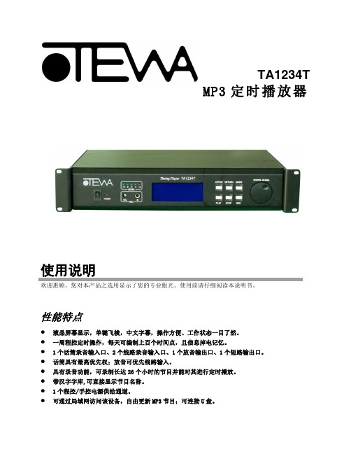
图6
日 01:30:00 开 1 无 日 02:22:11 关 2 有 一 00:00:56 … 3 停 二 10:00:00 开 ∞ 有 二 11:12:00 关 … 无
浏览界面
在图 6 界面下, 调整星期项参数用于定位所要浏览的具体日期, 调整星期项后面的时间项参
数,用于定位所要浏览的具体时间点.然后按确定按钮便进入了浏览界面,其中一个定时点呈
名称: 剩余空间:26’11” 状态:无操作
录音
试听
浏览
节目制作界面
退出
1)、录音
在节目制作界面下,旋转操作键选中并按下录音项进入录音界面。
名称:REC0001 剩余空间:26’11” 状态:正在录音 00 : 00 : 06
停止
试听
浏览
退出
录音界面
屏幕显示所剩录音空间。接好音源(话筒输入、线路输入),默认录音名称为:REC0001,录音 节目的名称可以修改:通过局域网在电脑上可修改录制节目的名称,旋转操作键选中录音项并按下即 开始录音。按下停止则停止录音并自动保存所录制的节目. 选中并按下退出按键,会自动保存录制 的节目并返回到操作选项界面。
弹簧夹 背对您
T-568A 接法从 1-8 的颜色 分别是:绿白,绿,橙白, 蓝,蓝白,橙,棕白,棕
弹簧夹 背对您
T-568B 接法从 1-8 的颜色 分别是:橙白,橙,绿白, 蓝,蓝白,绿,棕白,棕
本公司所配备的网线是用来通过网络交换机接入局域网更改设备节目的,为 T-568A~ T-568A 接法。用户若要本设备直接连接电脑的网卡,则网线要用 T-568A~T-568B 接法,可自 己参照上图制作。
警 告!
功率超过 1000W 的设备电源 不可接入后面板的定时电源 接口!
功放机说明书

功放机说明书篇一:功放的说明书说明书一、面板布置:1、本功放由功放、播放器、电平指示器、扬声器四个模块组成。
其中功放有放大音频信号的功能,可把播放器音频、外接音频、话筒音频信号放大,通过调节旋钮可改变信号的大小。
播放器有读取内存卡里的音频文件并转化成音频信号(另有收音机功能)的功能。
电平指示模块是通过计算音频信号,获取音频里音调的高低信号,再通过led灯显示出来,具有装饰的功能。
扬声器是把音频信号转化成声音信号的作用。
2、正前方:电平指示 1314⑥⑦⑧⑨⑩11 12①②③④⑤左声道右声道①电源指示灯、②音频输入、③音量旋钮、④话筒音量旋钮、⑤话筒输入、⑥播放器电源开关、⑦上一曲/音量-、⑧播放/暂停、⑨下一曲/音量+、⑩播放模式、11数据线插孔、12 usb插孔、13播放器显示屏、14 sd卡插孔(注:11、12、14插孔都是输入插孔,不能输出)3、正后方:变压器变压器线散热器遥控器电源线耳机插孔扬声器插头注意:1、使用前检查电源线和变压器线是否完好,外层绝缘皮是否有破损,若有破损则需要用电胶布粘住,防止皮肤接触而触电。
2、通电时最好不要触碰变压器和变压线。
3、使用时禁止触碰散热器、变压器,防止因温度过高而烫伤。
4、当使用耳机听音频时,只需把耳机插入耳机插孔,但要注意,在使用耳机之前要控制好音量,防止音量过大而损坏耳机。
一般操作是先把音量调为最小,插入耳机后再慢慢增大。
二、使用步骤:1、打开电源:在打开电源前先把音乐音量,话筒音量④调为最小,并确定自带播放器开关⑥处于关闭状态。
然后把电源线接电,则电源指示灯会亮①。
2、接音频:音频有两种,一种是外接音频输入②,另外一种是自带播放器输入,其优先级是外接音频输入高于自带播放器音频输入。
(1)外接音频输入需用一根3.5mm音频线与外界播放器连接,另外一端必须接到功放的外接“音频输入”②插孔,注意播放器的音量③应适当,否则将会烧坏功放芯片和损坏喇叭。
(2)自带播放器输入:首先把优盘或sd卡插入相应位置11、12、13,然后把播放器开关打开⑥,启动自带播放器。