4位超前进位加法器
4bits超前加法进位器的全定制设计_微电子卓越班数字集成电路课程设计报告

数字集成电路课程设计题目:4 bits超前加法进位器地全定制设计姓名:席高照学号: 111000833学院:物理与信息工程学院专业:微电子(卓越班)年级: 2010级指导教师:陈群超(签名)2013 年 6 月 3 日目录第1章概述 01.1课程设计目地.......................................... 错误!未定义书签。
1.2课程设计地主要内容.................................... 错误!未定义书签。
1.2.1设计题目.......................................... 错误!未定义书签。
1.2.2设计内容.......................................... 错误!未定义书签。
第2章功能分析及逻辑分析 (2)2.1功能分析 (2)2.2推荐工作条件 (3)2.3电性能 (7)2.4真值表 ................................................ 错误!未定义书签。
2.5表达式 (6)2.6电路图...................................................................... 错误!未定义书签。
第3章电路设计与器件参数设计83.1性能指标: ............................................ 错误!未定义书签。
3.2模块划分 (7)3.2.1输出级电路设计 (7)3.2.2内部反相器 (9)3.2.3内部电路等效 (8)3.2.4输入级电路 (10)3.2.5输出缓冲级电路 (10)3.2.6输入、输出保护电路 (10)3.3本章小结 (10)第4章电路模拟与仿真................................................................................................... 错误!未定义书签。
BCD-7段译码器、四位超前进位加法器、四位数值比较器
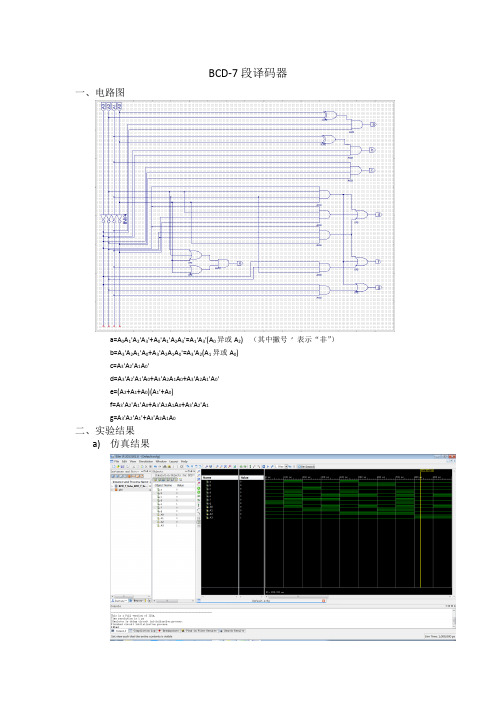
BCD-7段译码器一、电路图a=A0A1'A2'A3'+A0'A1'A2A3'=A1'A3'(A0异或A2) (其中撇号’表示“非”)b=A3'A2A1'A0+A3'A2A1A0'=A3'A2(A1异或A0)c=A3'A2'A1A0'd=A3'A2'A1'A0+A3'A2A1A0+A3'A2A1'A0'e=(A2+A1+A0)(A1'+A0)f=A3'A2'A1'A0+A3'A2A1A0+A3'A2'A1g=A3'A2'A1'+A3'A2A1A0二、实验结果a)仿真结果{A3,A2,A1,A0}取遍0000,0001,0010,0011,0100,0101,0110,0111,1000,1001,结果均符合要求。
b)在实际FPGA中实验结果:符合要求。
三、结果分析a)输入值范围在0000-1001之间时,可以实现BCD码转7段显示码功能。
但在输入值超出范围时将显示乱码。
若不允许乱码出现,可将卡诺图中的不确定性项d全部改为需要的值,以提示输入错误或不显示任何内容。
但这将使电路规模大幅增加。
b)关键路径含3级门。
其中a,b使用了异或门,但异或门的输入均为原变量。
通过异或门的路径最多只需通过2级逻辑门。
若全部改用与门、或门,则必须有反变量输入,使a,b的关键路径仍然含有3级门,因此不能提升速度,但每个函数必需的带宽都将从4增加为8。
如果与门、或门过剩,异或门不足,且带宽不是制造过程中的制约因素,则更适宜使用与门、或门。
由以上可知,使用异或门可以避免反变量输入,节约1级非门的相应时间,节约带宽。
d函数在卡诺图的分布导致其无法很好化简,因此将占用较多带宽。
用Verilog HDL语言编写的四位超前进位加法器

——Verilog HDL语言
四位超前进位加法器的进位是并 行同时产生的,能够极大的减 少加法器由进位引起的延时。 增加了逻辑器件,但有效的减 少的延迟。进位是由ALU部件超 前算出,本位是由四个不含进 位的加法器算出。
Verilog HDL代码如下: module jiafaqi_4(x,y,c0,c4,f); //四位超前进位加法器 input [4:1]x; //四位x值 input [4:1]y; //四位y值 output [4:1]f; //四位加和f input c0; //上一的级进位 output c4; //向下一级的进位 wire [3:1]c; //超前进位 wire [4:1]p; wire [4:1]g; wire [4:1]cd; assign p=x|y; assign g=x&y;
module jiafaqi_1(x,y,c0,f); //一位加法器模块 input x; input y; input c0; output f; assign f=(x^y)^c0; endmodule //该一位加法器只有本位输出,不含向下一级 的进位输出,进位输出是由顶层模块的并 行超前进位提供
// 在BASYS2开发板上的管脚配置 NET "c4" LOC = N5; NET "c0" LOC = A7; NET "x[1]" LOC = P11; NET "x[2]" LOC = L3; NET "x[3]" LOC = K3; NET "x[4]" LOC = B4; NET "y[1]" LOC = G3; NET "y[2]" LOC = F3; NET "y[3]" LOC = E2; NET "y[4]" LOC = N3; NET "f[1]" LOC = M5; NET "f[2]" LOC = M11; NET "f[3]" LOC = P7; NET "f[4]" LOC = P6;
4bits超前加法进位器的全定制设计微电子卓越班数字集成电路课程设计报告

数字集成电路课程设计题目:4 bits超前加法进位器的全定制设计姓名:席高照学号:111000833学院:物理与信息工程学院专业:微电子(卓越班)年级:2010级指导教师:群超(签名)2013 年 6 月 3 日目录第1章概述 (1)1.1课程设计目的 (1)1.2课程设计的主要容 (1)1.2.1设计题目 (1)1.2.2设计容 (1)第2章功能分析及逻辑分析 (2)2.1功能分析 (2)2.2推荐工作条件 (3)2.3电性能 (3)2.4真值表 (6)2.5表达式 (6)2.6电路图 (7)第3章电路设计与器件参数设计 (8)3.1性能指标: (8)3.2模块划分 (8)3.2.1输出级电路设计 (8)3.2.2部反相器 (9)3.2.3部电路等效 (9)3.2.4输入级电路 (10)3.2.5输出缓冲级电路 (10)3.2.6输入、输出保护电路 (10)3.3本章小结 (11)第4章电路模拟与仿真 (12)4.1电路搭建 (12)4.1.1建立新库 (12)4.1.2建立SCHEMATIC VIEW (13)4.1.3建立SYMBOL (14)4.1.4建立总体电路SCHEMATIC VIEW (14)4.1.5建立总体SYMBOL (15)4.1.6测试电路 (16)4.2功能仿真 (16)4.3功耗仿真 (18)4.4仿真结果分析 (18)4.5本章小结 (18)5.2反相器版图 (19)5.3输入级 (20)5.4输出级 (20)5.5输出缓冲 (20)5.6异或门 (21)5.7或非门 (23)5.8与非门 (24)5.9整体版图 (25)5.10本章小结 (25)心得 (26)参考文献 (27)附录 (28)附录174LS283中文资料 (28)第1章概述1.1 课程设计目的•综合应用已掌握的知识•熟悉集成电路设计流程•熟悉集成电路设计主流工具•强化学生的实际动手能力•培养学生的工程意识和系统观念•培养学生的团队协作能力1.2 课程设计的主要容1.2.1 设计题目4bits超前进位加法器全定制设计1.2.2 设计要求Vdd=1.8V,VoH=4.6V,Vol=0.4V可驱动10个LSTTL电路(相对于15pf电容负载)1.2.3 设计容•功能分析及逻辑分析•电路设计及器件参数设计•估算功耗与延时•电路模拟与仿真•版图设计•版图数据提交及考核,课程设计总结第2章功能分析及逻辑分析2.1功能分析74283为4为超前进位加法器,不同于普通串行进位加法器由低到高逐级进位,超前进位加法器所有位数的进位大多数情况下同时产生,运算速度快,电路结构复杂。
四位加法器论文

四位超前进位加法器摘要:由于串行进位加法器的速度受到进位信号的限制,人们又设计了一种多位数超前进位加法逻辑电路,使每位的进位只由加数和被加数决定,而与低位的进位无关。
现在介绍超前进位的概念。
关键词:加法器;LabVIEW;示波器LabVIEW(Laboratory Virtual instrument Engineering)是一种图形化的编程语言,它广泛地被工业界、学术界和研究实验室所接受,视为一个标准的数据采集和仪器控制软件。
LabVIEW集成了与满足GPIB、VXI、RS-232和RS-485协议的硬件及数据采集卡通讯的全部功能。
它还内置了便于应用TCP/IP、ActiveX等软件标准的库函数。
这是一个功能强大且灵活的软件。
利用它可以方便地建立自己的虚拟仪器,其图形化的界面使得编程及使用过程都生动有趣。
传统文本编程语言根据指令的先后顺序决定程序执行顺序,但LabVIEW 则采用数据流编程方式,程序框图中节点之间的数据流向决定了VI 及函数的执行顺序。
LabVIEW 提供很多外观与传统仪器(如示波器、万用表)类似的控件,可用来方便地创建用户界面。
用户界面在LabVIEW 中被称为前面板。
使用图标和连线,可以通过编程对前面板上的对象进行控制。
这就是图形化源代码,又称G 代码。
LabVIEW 的图形化源代码在某种程度上类似于流程图,因此又被称作程序框图。
LabVIEW尽可能利用了技术人员、科学家、工程师所熟悉的术语、图标和概念。
因此,LabVIEW是一个面向最终用户的工具。
它可以增强你构建自己的科学和工程系统的能力,提供了实现仪器编程和数据采集系统的便捷途径。
使用它进行原理研究、设计、测试并实现仪器系统时,可以大大提高工作效率。
利用LabVIEW,可产生独立运行的可执行文件。
设计内容设计一个四位加法器,要求要有超前进位。
设计原理超前进位加法的特点是进位的运算,在数值结果的运算方面感觉没有什么特别。
4bits超前进位加法器全定制设计实验报告

TPLH
Propagation Delay Time
A1~A4,B1~B4到C4
3
ns
TPHL
3
tT
2.5
tP
2.5
Av Power
4
Layout Area
150*180
2.5真值表
2.6逻辑图
工艺的主要参数(smic18工艺)
参数
参数定义
PMOS数值
NMOS数值
U0
迁移率
8.661m
34m
Vth
-0.4
mA
IOL
Low Level OutputVoltage
8
mA
2.3直流特性
Symbol
Parameter
Test Condition
Value
Units
TA=25°C
Min
Typ
Max
VOH
High Level OutputVoltage
VCC=Min,IOH=Max
VIL=Max,VIH=Min
mA
C0
-0.4
II
InputCurrent @ Max Input Voltage
VCC=Max
VI=7.2V
A,B
0.2
mA
C0
0.1
ICC
Supply Current
VCC=Maxl
Parameter
From (Input )to (Ouput)
Test Condition
(2)点选LM视窗上面的工具列File→New→Library;
(3)会产生New Library画面;
(4)在框内填入库名;
四位超前进位加法器
1.课程设计名称四位超前进位加法器2.课程设计内容设计一个四位加法器,要求要有超前进位,减小输出的延迟,采用0.13um工艺设计。
3.课程设计目的训练学生综合运用学过的数字集成电路的基本知识,独立设计相对复杂的数字集成电路的能力。
4.课程设计要求4.1、按设计指导书中要求的格式书写,所有的内容一律打印;4.2、报告内容包括设计过程、仿真的HSPICE网表,软件仿真的结果及分析、延时的手工计算;4.3、要有整体电路原理图,仿真的波形图;4.4、软件仿真必须要有必要的说明;要给出各个输入信号的具体波形和输出信号的测试结果。
4.5、写出对应的HSPICE设计网表,网表仿真结果符合设计要求。
把仿真图形附在报告上。
4.6、设输入端的电容为C,输出端的负载电容为5000C inv,从输入到输出任意找一通inv路,优化通路延时,手工计算确定通路中每个门对应的晶体管的尺寸。
每组三个同学选择不能为同一通路。
此部分的计算参数可采用书中第六章的参数。
4.7、各种器件的具体结构可参考阎石的《数字电子技术基础》一书。
不允许有完全一样的报告,对于报告完全相同者,记为不及格。
5.使用软件软件为HSPICE和COSMOS-SCOPE。
6.课程设计原理由全加器的真值表可得S i和C i的逻辑表达式:定义两个中间变量G i和P i:当A i=B i=1时,G i=1,由C i的表达式可得C i=1,即产生进位,所以G i 称为产生量变。
若P i=1,则A i·B i=0,C i=C i-1,即P i=1时,低位的进位能传送到高位的进位输出端,故P i称为传输变量,这两个变量都与进位信号无关。
将G i和P i代入S i和C i得:进而可得各位进位信号的逻辑表达如下:根据逻辑表达式做出电路图(如图):逻辑功能图中有2输入异或门,2输入与门,3输入与门,4输入与门,2输入或门,3输入或门,4输入或门,其转化成CMOS晶体管图如下:7.课程设计网表*xor 2.subckt xor2 a b c d fmxorpa 1 a vdd vdd pmos l=2 w=8 mxorpb f d 1 vdd pmos l=2 w=8 mxorpc 2 b vdd vdd pmos l=2 w=8 mxorpd f c 2 vdd pmos l=2 w=8 mxorna f a 3 0 nmos l=2 w=4 mxornb 3 b 0 0 nmos l=2 w=4 mxornc f c 4 0 nmos l=2 w=4 mxornd 4 d 0 0 nmos l=2 w=4.ends xor2*and2.subckt and2 a b fmandpa f a vdd vdd pmos l=2 w=4 mandpb f b vdd vdd pmos l=2 w=4mandna f a 1 0 nmos l=2 w=4 mandnb 1 b 0 0 nmos l=2 w=4.ends and2*and3.subckt and3 a b c fmandpa f a vdd vdd pmos l=2 w=4 mandpb f b vdd vdd pmos l=2 w=4 mandpc f c vdd vdd pmos l=2 w=4 mandna f a 1 0 nmos l=2 w=6 mandnb 1 b 2 0 nmos l=2 w=6 mandnc 2 c 0 0 nmos l=2 w=6.ends and3*and4.subckt and4 a b c d fmandpa f a vdd vdd pmos l=2 w=4 mandpb f b vdd vdd pmos l=2 w=4 mandpc f c vdd vdd pmos l=2 w=4 mandpd f d vdd vdd pmos l=2 w=4 mandna f a 1 0 nmos l=2 w=8 mandnb 1 b 2 0 nmos l=2 w=8 mandnc 2 c 3 0 nmos l=2 w=8 mandnd 3 d 0 0 nmos l=2 w=8.ends and4*or2.subckt or2 a b fmorpa 1 a vdd vdd pmos l=2 w=8 morpb f b 1 vdd pmos l=2 w=8 mna f a 0 0 nmos l=2 w=4mnb f b 0 0 nmos l=2 w=4.ends or2*or3.subckt or3 a b c fmorpa 1 a vdd vdd pmos l=2 w=12 morpb 2 b 1 vdd pmos l=2 w=12 morpc f c 2 vdd pmos l=2 w=12 mna f a 0 0 nmos l=2 w=4mnb f b 0 0 nmos l=2 w=4mnc f c 0 0 nmos l=2 w=4.ends or3*or4.subckt or4 a b c d fmorpa 1 a vdd vdd pmos l=2 w=16morpb 2 b 1 vdd pmos l=2 w=16morpc 3 c 2 vdd pmos l=2 w=16morpd f d 3 vdd pmos l=2 w=16mna f a 0 0 nmos l=2 w=4mnb f b 0 0 nmos l=2 w=4mnc f c 0 0 nmos l=2 w=4mnd f d 0 0 nmos l=2 w=4.ends or4*not.subckt not a fmnotpa f a vdd vdd pmos l=2 w=4 mnotna f a 0 0 nmos l=2 w=2.ends not *反相器*or21.subckt or21 a b fxor2 a b 1 or2xnot 1 f not.ends or21 *2输入或门*or31.subckt or31 a b c fxor3 a b c 1 or3xnot 1 f not.ends or31 *3输入或门*or41.subckt or41 a b c d fxor4 a b c d 1 or4xnot 1 f not.ends or41 *4输入或门*xor21.subckt xor21 a b fxm a A5 notxn b B5 notxxor a b A5 B5 f xor2.ends xor21 * 2输入异或门*and21.subckt and21 a b fxand2 a b 1 and2xnot 1 f not.ends and21 *2输入与门*and31.subckt and31 a b c fxand3 a b c 1 and3xnot 1 f not.ends and31 *3输入与门*and41.subckt and41 a b c d fxand4 a b c d 1 and4xnot 1 f not.ends and41 *4输入与门xxor211 a1 b1 p1 xor21xxor212 a2 b2 p2 xor21xxor213 a3 b3 p3 xor21xxor214 a4 b4 p4 xor21xand211 a1 b1 g1 and21xand212 a2 b2 g2 and21xand213 a3 b3 g3 and21xand214 p1 c0 m0 and21xor211 m0 g1 c1 or21 *进位C1xand311 p2 p1 c0 m1 and31xand215 p2 g1 m2 and21xor312 g2 m1 m2 c2 or31 *进位C2 xand411 p3 p2 p1 c0 m3 and41xand313 p3 p2 g1 m4 and31xand216 p3 g2 m5 and21xor412 m3 m4 m5 g3 c3 or41 *进位C3 xxor215 p1 c0 s1 xor21 *输出s1xxor216 p2 c1 s2 xor21 *输出s2xxor217 p3 c2 s3 xor21 *输出s3xxor218 p4 c3 s4 xor21 *输出s4.include "c:\lib\130nm_bulk.l"tt.opt scale=0.05u.global vdd gndvdd vdd 0 1.2va1 a1 0 pulse 1.2 1.2 20n 1f 1f 30n 100nva2 a2 0 pulse 0 0 20n 1f 1f 30n 100nva3 a3 0 pulse 0 0 20n 1f 1f 30n 100nva4 a4 0 pulse 0 0 20n 1f 1f 30n 100nvb1 b1 0 pulse 1.2 1.2 20n 1f 1f 30n 100n vb2 b2 0 pulse 1.2 1.2 20 1f 1f 30n 100nvb3 b3 0 pulse 0 0 20n 1f 1f 30n 100nvb4 b4 0 pulse 1.2 1.2 20n 1f 1f 30n 100nvc0 c0 0 pulse 0 0 4n 1f 1f 0n 100n.tran 1n 100n.plot tran v(s1).plot tran v(s2).plot tran v(s3).plot tran v(s4).end8.结果及分析由波形可知:当输入a1=1,b1=1,前一级进位c0=0时,s1=a1+b1+c0=0,下一级进位c1=1.由波形可知:当输入a2=0,b2=1,前一级进位c1=1时,s2=a2+b2+c1=0,下一级进位c2=1.由波形可知:当输入a3=0,b3=0,前一级进位c2=1时,s3=a3+b3+c2=1,下一级进位c3=0.由波形可知:当输入a4=0,b4=1,前一级进位c3=0时,s4=a4+b4+c2=1。
数字集成电路课程设计报告-4bits超前进位加法器全定制设计
第1章概述1.1 课程设计目的•综合应用已掌握的知识•熟悉集成电路设计流程•熟悉集成电路设计主流工具•强化学生的实际动手能力•培养学生的工程意识和系统观念•培养学生的团队协作能力1.2 课程设计的主要内容1.2.1 设计题目4bits超前进位加法器全定制设计1.2.2 设计要求整个电路的延时小于2ns整个电路的总功耗小于20pw总电路的版图面积小于60*60um1.2.3 设计内容功能分析及逻辑分析估算功耗与延时电路模拟与仿真版图设计版图数据提交及考核,课程设计总结第2章功能分析及逻辑分析2.1 功能分析74283为4位超前进位加法器,不同于普通串行进位加法器由低到高逐级进位,超前进位加法器所有位数的进位大多数情况下同时产生,运算速度快,电路结构复杂。
其管脚如图2-1所示:图2-1 74283管脚图2.2推荐工作条件(根据SMIC 0.18工艺进行修改)表2-1 SMIC 0.18工艺的工作条件2.3直流特性(根据SMIC 0.18工艺进行修改)表2-2 SMIC 0.18直流特性2.4交流(开关)特性(根据SMIC 0.18工艺进行修改)表2-3SMIC 0.18工艺交流(开关)特性2.5真值表表2-4 4位超前进位加法器真值表2.6表达式定义两个中间变量Gi和Pi:所以:进而可得各位进位信号的罗辑表达如下2.7电路原理图超前进位加法器原理:对于一个N位的超前进位组,它的晶体管实现具有N+1个并行分支且最多有N+1个晶体管堆叠在一起。
由于门的分支和晶体管的堆叠较多使性能较差,所以超前进位计算在实际中至多智能限制于2或4位。
为了建立非常快速的加法器,需要把进位传播和进位产生组织成递推的树形结构,如图2-2所示。
一个比较有效的实现方法是把进位传播层次化地分解成N位的子组合:Co,0=GO+POCi,0Co,1=G1+P1G0+P1P0 Ci,0=( G1+P1G0)+(P1P0) Ci,0=G1:0+P1:0 Ci,0Co,2=G2+P2G1+P2P1G0+P2P1P0Ci,0=G2+P2Co,1 2-1 Co,3=G3+P3 G2+P3P2G1+P3P2P1G0+P3P2P1P0Ci,0=(G3+P3G2)+(P3P2)Co,1=G3:2+P3:2Co,1 在公式2-1中,进位传播过程被分解成两位的子组合。
4位超前进位加法器
4位超前进位加法器详细设计姓名:魏可望(23)班级:微电子1102指导老师:杜慧敏日期:2014年4月29日1设计目标 (3)1.1功能定义 (3)1.2引脚描述 (3)1.2.1 4位超前进位加法器系统级信号 (3)1.2.2 4位超前进位加法器输入接口定义 (3)1.2.3 4位超前进位加法器的器输出接口定义 (3)2 模块设计 (3)3测试 (4)4设计开发环境 (4)5设计开发计划 (4)1设计目标1.1功能定义本文描述4位超前进位加法器的详细设计方案。
其功能是求出4位超前进位加法器功能,并在FPGA开发板上验证设计的正确性。
1.2引脚描述1.2.1 4位超前进位加法器单元系统级信号1.2.2 4位超前进位加法器输入接口定义1.2.3 4位超前进位加法器输出接口定义2 模块设计本设计按要求,用assign语句设计4位超前进位加法器。
3测试本单元电路控制逻辑采用systemverilog断言描述状态信息测试,数据通路部分用采用sysetemverilog随机验证的方法,并结合覆盖率检测,做到100%验证。
将本设计下载到Sparten 3E开发板上,将计数器的输出连接到LED灯上,以验证设计的正确性。
4设计开发环境语言级设计:Verilog综合工具:xilinx 14.7rFPGA设计和仿真工具:ISE13.2,synopsys VCS布局和布线工具:appllo ,模拟设计和仿真工具: modelsim寄生参数提取和仿真工具: star_sim RC5设计开发计划附录:4位超前进位加法器源代码:module add_ahead4(sum,cout,a,b,cin);input[3:0] a,b;input cin;output[3:0] sum;output cout;wire[3:0] G,P;wire[3:0] C,sum;assign G[0]=a[0]&b[0];assign P[0]=a[0]|b[o];assign C[0]=cin;assign sum[0]=G[0]^P[0]^C[0];assign G[1]=a[1]&b[1];assign P[1]=a[1]|b[1];assign C[1]=G[0]|(P[0]&cin); assign sum[1]=G[1]^P[1]^C[1]; assign G[2]=a[2]&b[2]; assign P[2]=a[2]|b[2];assign C[2]=G[1]|(P[1]&C[1]); ssign sum[2]=G[2]^P[2]^C[2]; assign G[3]=a[3]&b[3]; assign P[3]=a[3]|b[3];assign C[3]=G[2]|(P[2]&C[2]); assign sum[3]=G[3]^P[3]^C[3]; assign cout=G[3]|(P[3]&C[3]); endmodule。
数字电路课程设计之超前进位加法器
reg
Cin;
wire[3:0] S;
wire
Cout;
carry_look_add CAL (.A(A),.B(B),.Cin(Cin),.Cout(Cout),.S(S)); initial begin
#10 A=4'd0;B=4'd0;Cin=0; #10 A=4'd11;B=4'd1;Cin=0; #10 A=4'd10;B=4'd12;Cin=0; #10 A=4'd11;B=4'd4;Cin=0; #100 $stop; end endmodule
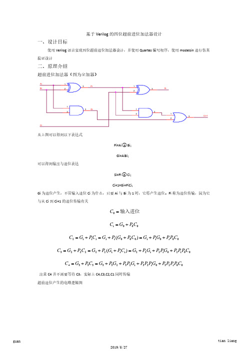
Pi=Ai○+ Bi;
可以得到输出与进位表达
Gi=AiBi;
Si=Pi○+ Ci;
Ci+1=Gi+PiCi; Gi 为进位产生,不管输入进位 Ci 为什么,只要 Ai 与 Bi 为 1 时,它将产生进位。Pi 称为进位传输,因为它 与从 Ci 到 Ci+1 的进位传输有关
C0 = 输入进位
C1 = G0 + P0C0
Half_Add H3(.a(A[2]),.b(B[2]),.s(v6),.c(v5));
Half_Add H4(.a(A[3]),.b(B[3]),.s(v8),.c(v7));
carry_look
CL1(.C0(Cin),.P0(v2),.G0(v1),.P1(v4),.G1(v3),.P2(v6),.G2(v5),.P3(v8),.G3(v7),.C1(o1),.C2(o2),.C3(o3),.C4(Cout));
注意 C4 并不需要等待 C3,实际上 C4,C3,C2,C1 同时传输 超前进位产生的电路逻辑图
数字电路课程设计之超前进位加法器

# MACRO ./mul_run_msim_rtl_verilog.do PAUSED at line 14
通过查阅资料将 Verilog 测试文件
Timsbench 文件没有实例化,修改为
修改后仿真 OK 参考文献: 1.数字设计与 Verilog 实现 M.Morris Mano 著 第五版
Pi=Ai○+ Bi;
可以得到输出与进位表达
Gi=AiBi;
Si=Pi○+ Ci;
Ci+1=Gi+PiCi; Gi 为进位产生,不管输入进位 Ci 为什么,只要 Ai 与 Bi 为 1 时,它将产生进位。Pi 称为进位传输,因为它 与从 Ci 到 Ci+1 的进位传输有关
C0 = 输入进位
C1 = G0 + P0C0
instance name in instantiation of 'carry_look_add'.
#
#
Region: /carry_look_add_tb
# Error loading design
# Error: Error loading design
#
Pausing macro execution
基于 Verilog 的四位超前进位加法器设计
使用 Verilog 语言实现四位超前进位加法器设计,并使用 Quartes 编写程序,使用 modelsin 进行仿真
验证设计
二、原理介绍
超前进位加法器(图为全加器)
Ai
1
3
Pi
Bi
2
1
3
Si
2
1 3 Gi
2
Ci
1
3
计算机组成原理课程设计—超前进位加法器的设计资料
沈阳航空航天大学课程设计报告课程设计名称:计算机组成原理课程设计课程设计题目:超前进位加法器的设计院(系):计算机学院专业:班级:学号:姓名:指导教师:完成日期:沈阳航空航天大学课程设计报告目录第1章总体设计方案 (1)1.1设计原理 (1)1.2设计思路 (2)1.3设计环境 (3)第2章详细设计方案 (4)2.1顶层方案图的设计与实现 (4)2.1.1创建顶层图形设计文件 (4)2.1.2器件的选择与引脚锁定 (5)2.1.3编译、综合、适配 (7)2.2功能模块的设计与实现 (7)2.2四位超前进位加法器模块的设计与实现 (7)2.3仿真调试 (9)第3章编程下载与硬件测试 (11)3.1编程下载 (11)3.2硬件测试及结果分析 (11)参考文献 (13)附录(程序清单或电路原理图) (14)第1章总体设计方案1.1设计原理八位超前进位加法器,可以由2个四位超前进位加法器构成。
由第一个四位超前进位加法器的进位输出作为第二个超前进位加法器的进位输入即可实现八位超前进位加法器的设计。
超前进位产生电路是根据各位进位的形成条件来实现的。
只要满足下述条件,就可形成进位C1、C2、C3、C4。
所以:第一位的进位C1=X1*Y1+(X1+Y1)*C0第二位的进位C2=X2*Y2+(X2+Y2)*X1*Y1+(X2+Y2)(X1+Y1)C0第三位的进位C3=X3*Y3+(X3+Y3)X2*Y2+(X3+Y3)*(X2+Y2)*X1*Y1+(X3+Y3)(X2+Y2)(X1+Y1)*C0第四位的进位C4=X4*Y4+(X4+Y4)*X3*Y3+(X4+Y4)*(X3+Y3) * X2*Y2+(X4+Y4)(X3+Y3)(X2+Y2)*X1*Y1+(X4+Y4)(X3+Y3)(X2+Y2)(X1+Y1)*C0 下面引入进位传递函数Pi和进位产生函数Gi的概念。
它们定义为:Pi=Xi+YiGi=Xi*YiP1的意义是:当X1和Y1中有一个为1时,若有进位输入,则本位向高位传递此进位。
四位超前进位加器原理
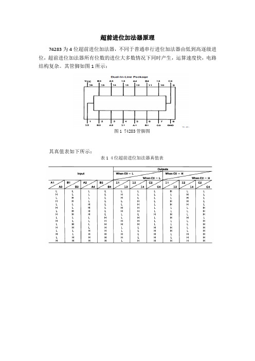
超前进位加法器原理74283为4位超前进位加法器,不同于普通串行进位加法器由低到高逐级进位,超前进位加法器所有位数的进位大多数情况下同时产生,运算速度快,电路结构复杂。
其管脚如图1所示:图1 74283管脚图其真值表如下所示:表1 4位超前进位加法器真值表由全加器的真值表可得Si 和Ci的逻辑表达式:定义两个中间变量Gi 和Pi:当Ai =Bi=1时,Gi=1,由Ci的表达式可得Ci=1,即产生进位,所以Gi称为产生量变。
若Pi =1,则Ai·Bi=0,Ci=Ci-1,即Pi=1时,低位的进位能传送到高位的进位输出端,故Pi称为传输变量,这两个变量都与进位信号无关。
将Gi 和Pi代入Si和Ci得:进而可得各位进位信号的逻辑表达如下:根据逻辑表达式做出电路图如下:逻辑功能图中有2输入异或门,2输入与门,3输入与门,4输入与门,2输入或门,3输入或门,4输入或门,其转化成CMOS晶体管图如下:电路网表如下:*xor 2.subckt xor2 a b c d fmxorpa 1 a vdd vdd pmos l=2 w=8 mxorpb f d 1 vdd pmos l=2 w=8 mxorpc 2 b vdd vdd pmos l=2 w=8 mxorpd f c 2 vdd pmos l=2 w=8 mxorna f a 3 0 nmos l=2 w=4 mxornb 3 b 0 0 nmos l=2 w=4 mxornc f c 4 0 nmos l=2 w=4 mxornd 4 d 0 0 nmos l=2 w=4.ends xor2*and2.subckt and2 a b fmandpa f a vdd vdd pmos l=2 w=4 mandpb f b vdd vdd pmos l=2 w=4 mandna f a 1 0 nmos l=2 w=4 mandnb 1 b 0 0 nmos l=2 w=4.ends and2*and3.subckt and3 a b c fmandpa f a vdd vdd pmos l=2 w=4 mandpb f b vdd vdd pmos l=2 w=4 mandpc f c vdd vdd pmos l=2 w=4 mandna f a 1 0 nmos l=2 w=6 mandnb 1 b 2 0 nmos l=2 w=6 mandnc 2 c 0 0 nmos l=2 w=6.ends and3*and4.subckt and4 a b c d fmandpa f a vdd vdd pmos l=2 w=4 mandpb f b vdd vdd pmos l=2 w=4 mandpc f c vdd vdd pmos l=2 w=4 mandpd f d vdd vdd pmos l=2 w=4 mandna f a 1 0 nmos l=2 w=8 mandnb 1 b 2 0 nmos l=2 w=8 mandnc 2 c 3 0 nmos l=2 w=8 mandnd 3 d 0 0 nmos l=2 w=8.ends and4*or2.subckt or2 a b fmorpa 1 a vdd vdd pmos l=2 w=8 morpb f b 1 vdd pmos l=2 w=8mna f a 0 0 nmos l=2 w=4mnb f b 0 0 nmos l=2 w=4.ends or2*or3.subckt or3 a b c fmorpa 1 a vdd vdd pmos l=2 w=12 morpb 2 b 1 vdd pmos l=2 w=12 morpc f c 2 vdd pmos l=2 w=12mna f a 0 0 nmos l=2 w=4mnb f b 0 0 nmos l=2 w=4mnc f c 0 0 nmos l=2 w=4.ends or3*or4.subckt or4 a b c d fmorpa 1 a vdd vdd pmos l=2 w=16 morpb 2 b 1 vdd pmos l=2 w=16 morpc 3 c 2 vdd pmos l=2 w=16 morpd f d 3 vdd pmos l=2 w=16mna f a 0 0 nmos l=2 w=4mnb f b 0 0 nmos l=2 w=4mnc f c 0 0 nmos l=2 w=4mnd f d 0 0 nmos l=2 w=4.ends or4*not.subckt not a fmnotpa f a vdd vdd pmos l=2 w=4 mnotna f a 0 0 nmos l=2 w=2.ends not *反相器*or21.subckt or21 a b fxor2 a b 1 or2xnot 1 f not.ends or21 *2输入或门*or31.subckt or31 a b c fxor3 a b c 1 or3xnot 1 f not.ends or31 *3输入或门*or41.subckt or41 a b c d fxor4 a b c d 1 or4xnot 1 f not.ends or41 *4输入或门*xor21.subckt xor21 a b fxm a A5 notxn b B5 notxxor a b A5 B5 f xor2.ends xor21 * 2输入异或门*and21.subckt and21 a b fxand2 a b 1 and2xnot 1 f not.ends and21 *2输入与门*and31.subckt and31 a b c fxand3 a b c 1 and3xnot 1 f not.ends and31 *3输入与门*and41.subckt and41 a b c d fxand4 a b c d 1 and4xnot 1 f not.ends and41 *4输入与门xxor211 a1 b1 p1 xor21xxor212 a2 b2 p2 xor21xxor213 a3 b3 p3 xor21xxor214 a4 b4 p4 xor21xand211 a1 b1 g1 and21xand212 a2 b2 g2 and21xand213 a3 b3 g3 and21xand214 p1 c0 m0 and21xor211 m0 g1 c1 or21 *进位C1xand311 p2 p1 c0 m1 and31xand215 p2 g1 m2 and21xor312 g2 m1 m2 c2 or31 *进位C2xand411 p3 p2 p1 c0 m3 and41xand313 p3 p2 g1 m4 and31xand216 p3 g2 m5 and21xor412 m3 m4 m5 g3 c3 or41 *进位C3xxor215 p1 c0 s1 xor21 *输出s1xxor216 p2 c1 s2 xor21 *输出s2xxor217 p3 c2 s3 xor21 *输出s3xxor218 p4 c3 s4 xor21 *输出s4.include "c:\lib\130nm_bulk.l"tt.opt scale=0.05u.global vdd gndvdd vdd 0 1.2va1 a1 0 pulse 1.2 1.2 20n 1f 1f 30n 100nva2 a2 0 pulse 0 0 20n 1f 1f 30n 100nva3 a3 0 pulse 0 0 20n 1f 1f 30n 100nva4 a4 0 pulse 0 0 20n 1f 1f 30n 100nvb1 b1 0 pulse 1.2 1.2 20n 1f 1f 30n 100n vb2 b2 0 pulse 1.2 1.2 20 1f 1f 30n 100nvb3 b3 0 pulse 0 0 20n 1f 1f 30n 100nvb4 b4 0 pulse 1.2 1.2 20n 1f 1f 30n 100nvc0 c0 0 pulse 0 0 4n 1f 1f 0n 100n.tran 1n 100n.plot tran v(s1).plot tran v(s2).plot tran v(s3).plot tran v(s4).end。
4位超前进位加法器原理
4位超前进位加法器原理
4位超前进位加法器是一种用于进行4位二进制数相加的电路,能够进行四位二进制数的相加,若两个4位二进制数相加结果超过4位,则可以产生一个进位。
其原理如下:
1. 输入:两个四位二进制数A和B以及一个进位输入Cin。
2. 输出:一个四位的和S和一个进位输出Cout。
3. 首先,对于每一位相加,可以使用一个全加器。
4. 对于最低位的相加,输入为A0、B0和Cin,输出为S0和
C0(即第一位的进位)。
5. 对于其他位的相加(A1+B1、C0+A2+B2、C1+A3+B3),
输入为A1、B1、C0,输出为S1和C1(即第二位的进位)。
6. 最后,输出为四位和S3和一个进位输出Cout,Cout等于最
高位相加的进位。
7. 这样,就能够实现4位超前进位加法器,并且能够处理进位的情况。
总之,4位超前进位加法器通过使用多个全加器来实现四位二
进制数的相加,并且能够产生进位。
设计一个4位超前进位加法器(数字逻辑课设)
数字逻辑课程设计题目:设计一个 4 位超前进位加法器
评语:
学院计算机工程班级计算
姓名学号
成绩指导老师黄斌刘丽莉
2016年7 月12日
真值表如下:
Ai Bi Ci-1Si
0000
0011
0101
0110
1001
1010
1100
1111
其卡诺图如下:
AB00011110
C
00101
11010
化简之后的表达式:S=Ai^Bi^Ci-1
进位c的表达式:
g p p p p g p p p g p p g p
下图为局部波形图:
举例:A=0000,B=1011,c_in=0,c=1011,c_out=0
四、实验小结。
通过这次课程设计,我感觉我对Verilog语言还是不够熟悉,在写的过程中需要经常询问同学,或是通过网上查询来解决一些语法上的问题,对于这个加法器,只会按照书本上的来写,不知道怎么修改,测试代码的循环用FOR循环写不出来,只好问同学用always循环。
超前进位4位加法器74LS283的VHDL程序实现
超前进位4位加法器74LS283的VHDL程序实现
由于串行多位加法器的高位相加时要等待低位的进位,所以速度受到
进位信号的限制而变慢,人们又设计了一种多位数超前进位加法器逻辑电路,
使每位求和结果直接接受加数和被加数而不必等待地位进位,而与低位的进位
信号无关,这就大大的提高了运算速度。
现在简单介绍超前进位的运算方法,
以及VHDL 可编程逻辑编程。
Library ieee;Use ieee.std_logic_1164.all;entity CQadd_Co is port(C0,A1,B1,A2,B2,A3,B3,A4,B4:In std_logic; S1,S2,S3,S4,Co:out std_logic);end CQadd_Co;architecture adder of CQadd_Co is signal c1,c2,c3,t1,t2,t3,t4,m1,m2,m3,m4:std_logic; signal P1,P2,P3,P4:std_logic; begin t1tips:感谢大家的阅读,本文由我司收集整编。
仅供参阅!。
[转]4位超前进位加法器代码及原理
![[转]4位超前进位加法器代码及原理](https://img.taocdn.com/s3/m/762c354832687e21af45b307e87101f69e31fb22.png)
[转]4位超前进位加法器代码及原理超前进位加法器module add4_head ( a, b, ci, s, pp, gg);input[3:0] a;input[3:0] b;input ci;output[3:0] s;output pp;output gg;wire[3:0] p;wire[3:0] g;wire[2:0] c;assign p[0] = a[0] ^ b[0];assign p[1] = a[1] ^ b[1];assign p[2] = a[2] ^ b[2];assign p[3] = a[3] ^ b[3];assign g[0] = a[0] & b[0];assign g[1] = a[1] & b[1];assign g[2] = a[2] & b[2];assign g[3] = a[3] & b[3];assign c[0] = (p[0] & ci) | g[0];assign c[1] = (p[1] & c[0]) | g[1];assign c[2] = (p[2] & c[1]) | g[2];assign pp = p[3] & p[2] & p[1] & p[0];assign gg = g[3] | (p[3] & (g[2] | p[2] & (g[1] | p[1] & g[0])));assign s[0] = p[0] ^ ci;assign s[1] = p[1] ^ c[0];assign s[2] = p[2] ^ c[1];assign s[3] = p[3] ^ c[2];endmodule⾸先要明确⼏个概念:p表⽰进位否决信号(pass),如果p为0就否决调前⼀级的进位输⼊。
否决的意思就是即使前⼀级有进位,本级也不会向后⼀级产⽣进位输出。
- 1、下载文档前请自行甄别文档内容的完整性,平台不提供额外的编辑、内容补充、找答案等附加服务。
- 2、"仅部分预览"的文档,不可在线预览部分如存在完整性等问题,可反馈申请退款(可完整预览的文档不适用该条件!)。
- 3、如文档侵犯您的权益,请联系客服反馈,我们会尽快为您处理(人工客服工作时间:9:00-18:30)。
TL F 642154LS283 DM54LS283 DM74LS283 4-Bit Binary Adders with Fast CarryJune1989 54LS283 DM54LS283 DM74LS2834-Bit Binary Adders with Fast CarryGeneral DescriptionThese full adders perform the addition of two4-bit binarynumbers The sum(R)outputs are provided for each bit andthe resultant carry(C4)is obtained from the fourth bitThese adders feature full internal look ahead across all fourbits This provides the system designer with partial look-ahead performance at the economy and reduced packagecount of a ripple-carry implementationThe adder logic including the carry is implemented in itstrue form meaning that the end-around carry can be accom-plished without the need for logic or level inversionFeaturesY Full-carry look-ahead across the four bitsY Systems achieve partial look-ahead performance withthe economy of ripple carryY Typical add timesTwo8-bit words25nsTwo16-bit words45nsY Typical power dissipation per4-bit adder95mWY Alternate Military Aerospace device(54LS283)is avail-able Contact a National Semiconductor Sales OfficeDistributor for specificationsConnection DiagramDual-In-Line PackageTL F 6421–1Order Number54LS283DMQB 54LS283FMQB 54LS283LMQBDM54LS283J DM54LS283W DM74LS283M or DM74LS283NSee NS Package Number E20A J16A M16A N16E or W16AC1995National Semiconductor Corporation RRD-B30M105 Printed in U S AAbsolute Maximum Ratings(Note)If Military Aerospace specified devices are required please contact the National Semiconductor Sales Office Distributors for availability and specifications Supply Voltage7V Input Voltage7V Operating Free Air Temperature RangeDM54LS and54LS b55 C to a125 C DM74LS0 C to a70 C Storage Temperature Range b65 C to a150 C Note The‘‘Absolute Maximum Ratings’’are those values beyond which the safety of the device cannot be guaran-teed The device should not be operated at these limits The parametric values defined in the‘‘Electrical Characteristics’’table are not guaranteed at the absolute maximum ratings The‘‘Recommended Operating Conditions’’table will define the conditions for actual device operationRecommended Operating ConditionsSymbol ParameterDM54LS283DM74LS283Units Min Nom Max Min Nom MaxV CC Supply Voltage4 555 54 7555 25V V IH High Level Input Voltage22V V IL Low Level Input Voltage0 70 8V I OH High Level Output Current b0 4b0 4mA I OL Low Level Output Current48mA T A Free Air Operating Temperature b55125070 C Electrical Characteristics over recommended operating free air temperature range(unless otherwise noted)Symbol Parameter Conditions MinTypMax Units (Note1)V I Input Clamp Voltage V CC e Min I I e b18mA b1 5V V OH High Level Output V CC e Min I OH e Max DM542 53 4V Voltage V IL e Max V IH e Min DM742 73 4V OL Low Level Output V CC e Min I OL e Max DM540 250 4 Voltage V IL e Max V IH e Min DM740 350 5VI OL e4mA V CC e Min DM740 250 4I I Input Current Max V CC e Max A B0 2mA Input Voltage V I e7V C00 1I IH High Level Input V CC e Max A B40m A Current V I e2 7V C020I IL Low Level Input V CC e Max A B b0 8mA Current V I e0 4V C0b0 4I OS Short Circuit V CC e Max DM54b20b100mA Output Current(Note2)DM74b20b100I CC1Supply Current V CC e Max(Note3)1934mA I CC2Supply Current V CC e Max(Note4)2239mA Note1 All typicals are at V CC e5V T A e25 CNote2 Not more than one output should be shorted at a time and the duration should not exceed one secondNote3 I CC1is measured with all outputs open all B inputs low and all other inputs at4 5V or all inputs at4 5VNote4 I CC2is measured with all outputs open and all inputs grounded2Switching Characteristics at V CC e5V and T A e25 C(See Section1for Test Waveforms and Output Load)From(Input)R L e2k XSymbol ParameterTo(Output)C L e15pF C L e50pF UnitsMin Max Min Maxt PLH Propagation Delay Time C0to2428ns Low to High Level Output R1 R2t PHL Propagation Delay Time C0to2430ns High to Low Level Output R1 R2t PLH Propagation Delay Time C0to2428ns Low to High Level Output R3t PHL Propagation Delay Time C0to2430ns High to Low Level Output R3t PLH Propagation Delay Time C0to2428ns Low to High Level Output R4t PHL Propagation Delay Time C0to2430ns High to Low Level Output R4t PLH Propagation Delay Time A i or B i2428ns Low to High Level Output to R it PHL Propagation Delay Time A i or B i2430ns High to Low Level Output to R it PLH Propagation Delay Time C0to1724ns Low to High Level Output C4t PHL Propagation Delay Time C0to1725ns High to Low Level Output C4t PLH Propagation Delay Time A i or B i1724ns Low to High Level Output to C4t PHL Propagation Delay Time A i or B i1726ns High to Low Level Output to C4Function TableTL F 6421–3 H e High Level L e Low LevelNote Input conditions at A1 B1 A2 B2 and C0are used to determine outputs R1and R2and the value of the internal carry C2 The values at C2 A3 B3 A4 andB4are then used to determine outputs R3 R4 and C43Logic DiagramLS283TL F 6421–245Physical Dimensions inches(millimeters)Ceramic Leadless Chip Carrier Package(E)Order Number54LS283LMQBNS Package Number E20A16-Lead Ceramic Dual-In-Line Package(J)Order Number54LS283DMQB or DM54LS283JNS Package Number J16A6Physical Dimensions inches(millimeters)(Continued)16-Lead Small Outline Molded Package(M)Order Number DM74LS283MNS Package Number M16A16-Lead Molded Dual-In-Line Package(N)Order Number DM74LS283NNS Package Number N16E754L S 283 D M 54L S 283 D M 74L S 2834-B i t B i n a r y A d d e r s w i t h F a s t C a r r yPhysical Dimensions inches (millimeters)(Continued)16-Lead Ceramic Flat Package (W)Order Number 54LS283FMQB or DM54LS283WNS Package Number W16ALIFE SUPPORT POLICYNATIONAL’S PRODUCTS ARE NOT AUTHORIZED FOR USE AS CRITICAL COMPONENTS IN LIFE SUPPORT DEVICES OR SYSTEMS WITHOUT THE EXPRESS WRITTEN APPROVAL OF THE PRESIDENT OF NATIONAL SEMICONDUCTOR CORPORATION As used herein 1 Life support devices or systems are devices or 2 A critical component is any component of a life systems which (a)are intended for surgical implant support device or system whose failure to perform can into the body or (b)support or sustain life and whose be reasonably expected to cause the failure of the life failure to perform when properly used in accordance support device or system or to affect its safety or with instructions for use provided in the labeling can effectivenessbe reasonably expected to result in a significant injury to the userNational Semiconductor National Semiconductor National Semiconductor National Semiconductor CorporationEuropeHong Kong LtdJapan Ltd1111West Bardin RoadFax (a 49)0-180-530858613th Floor Straight Block Tel 81-043-299-2309This datasheet has been downloaded from: Datasheets for electronic components.。
