SE350调压器说明书
AVENTICS E P压力调节器系列ED05数据参数说明书
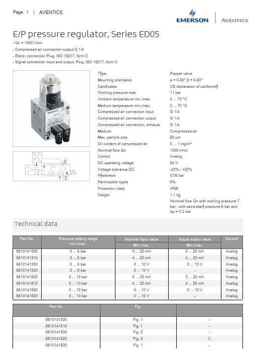
E/P pressure regulator, Series ED05- Qn = 1000 l/min- Compressed air connection output G 1/4- Electr. connection Plug, ISO 15217, form C- Signal connection input and output, Plug, ISO 15217, form CType Poppet valveMounting orientationα = 0-90° β = 0-90°Certificates CE declaration of conformityWorking pressure max11 barAmbient temperature min./max.0 ... 70 °CMedium temperature min./max.0 ... 70 °CCompressed air connection input G 1/4Compressed air connection output G 1/4Compressed air connection, exhaust G 1/4Medium Compressed airMax. particle size50 µmOil content of compressed air0 ... 1 mg/m³Nominal flow Qn1000 l/minControl AnalogDC operating voltage24 VVoltage tolerance DC-20% / +20%Hysteresis0.06 barPermissible ripple5%Protection class IP65Weight1,1 kgNominal flow Qn with working pressure 7bar , with secondary pressure 6 bar andΔp = 0.2 barMinimum working pressure = 0.5 bar + max. required secondary pressure, Additional pressure setting ranges available on request 1) Output 10V constant to supply a set point potentiometer.1) Core hole 15 mm deep for self-tapping screws M62) Universal threaded connection, suitable for G1/4 according to ISO 228/1:2000 and 1/4-27 NPTF3) Through holeConnect the plug via a shielded cable to ensure EMCa) Nominal input value b) Actual output valueThe E/P pressure control valve modulates the pressure corresponding to an analog electrical nominal input value.1) Operating pressure2) Working pressure3) Exhaust1) Operationalvoltage2) Input current nominal value (ohmic load 100 Ω, max. 50 mA.)The voltage at the nominal input value may not exceed 12 V.4) actual output value (max. total resistance of downstream devices 300 Ω).3) The operating voltage must be protected by an external M 1.6 A fuse. Connect plug 2 via a shielded cable to ensure EMC.A) Plug 1 B) Plug 21) Operationalvoltage2) Nominal input value voltage3) Actual output value (min. external ohmic load 1 kΩ)4) The operating voltage must be protected by an external M 1.6 A fuse. Connect plug 2 via a shielded cable to ensure EMC.A) Plug 1 B) Plug 21) Operationalvoltage2) Nominal input value voltage3) The operating voltage must be protected by an external M 1.6 A fuse. Connect plug 2 via a shielded cable to ensure EMC.A) Plug 1 B) Plug 24) Potentiometer control (0 - 2 kΩ (min.), 0 - 10 kΩ (max.))Your local contact:/contactus/EmersonAutomationSolutions/company/Emerson-Automation-SolutionsAn example configuration is depicted on the title page. The delivered product may thus vary from that in the illustration. Subject to change. This Document, as well as the data, specifications and other information set forth in it, are the exclusive property of AVENTICS GmbH. It may not be reproduced or given to third parties without its consent. Only use the AVENTICS products shown in industrial applications. Read the product documentation completely and carefully before using the product. Observe the applicable regulations and laws of the respective country. When integrating the product into applications, note the system manufacturer's specifications for safe use of the product. The data specified only serve to describe the product. No statements concerning a certain condition or suitability for a certain application can be derived from our information.The information given does not release the user from the obligation of own judgement and verification. It must be remembered that the products aresubject to a natural process of wear and aging.of the Emerson family of companies. All other marks are the property of their respective owners. © 2020 Emerson Electric Co.All rights reserved.2020-12。
磁性调压器用户手册-doc

用户手册注册商标中华人民共和国苏州昊海变压器有限公司电话: 6 62570125致顾客的公开信亲爱的顾客朋友:欢迎您使用我公司产品。
并且,对于您对我公司的信任,表示由衷地感谢!我公司自2002年获得UCAS认证有限公司颁发的ISO900《质量管理体系认证证书》以来,始终保持并严格执行管理体系标准规定和要求,以“优良品质、完善服务、满足要求、持续进步”为企业方针,以“用户的放心满意永远是我们信守的承诺”为宗旨。
在国内外广大用户中得到充分的好评,有极高的信誉,也因此都能顺利通过认证公司的例行监督和复查。
本公司具有完善、先进的测试设备和严格的检测手段,产品全部按产品标准和行业内较先进的工艺方式组织生产。
具有严格的工艺流程和健全的质量保证体系,从原材料进厂到产品出厂,实行全方位的质量检验和监督,从而使产品质量得以充分保证。
公司主要产品经变压器质量监督检验检测中心检测,各项指标全部符合GB或JB标准。
我公司长期配套于科研、军工、电子、光伏、铁路、冶炼、钢铁、机械、化工、建材等行业,并出口美国、法国、日本、孟加拉国、印度、朝鲜、越南、伊朗、台湾等国家和地区。
我们愿意为包括您在内的更多的客户,提供更加周到、更加满意的服务。
在您第一次安装和使用本产品之前,请您务必仔细阅读本手册,这会有助于您更好地使用本产品。
尤其是涉及人身、设备安全方面的内容,请您更加关注和留意。
并且,务请组织具有相应资格(资质)或具有相应专业知识的人员,来参与本产品的安装、使用和维护,这更有助于您安全、正确、高效地使用本产品。
我公司已经对本手册进行了仔细的校勘和核对,但我们不能保证本手册完全没有任何错误或疏漏。
我公司致力于不断改进产品功能和质量,因此保留对本手册中所描述的产品和程序以及本手册的内容进行更改,而不预先另行通知的权利。
本手册中的图片仅供参考,如果有个别图片与产品实物不符,请以实物为准。
本手册中对于本产品配件、附件等安装使用的描述,如果与配(附)件专有说明不一致时,请以它们各自专有的安装使用说明书为准。
ES350、400中文说明书(1)

ES350, ES400, ES350带氩气功能电刀ES350带氩气模块和血管闭合系统®功能电刀电外科设备使用说明书使用之前请阅读该手册,并以此作为进一步的参考。
2说明书中使用的标志:重要信息允许禁止 警告内容1. ES350的预期用途 (5)2. 电外科手术基础 (7)2.1 单极操作 (7)2.2 双极操作 (7)2.3 符号 (8)2.4 电外科配件 (9)3. 技术规格 (11)4. 设备列表 (13)5. 外表和结构 (14)6. 启动前的准备工作 (21)6.1 连接电源 (21)6.2 连接气管 (23)6.3 设置氩气气流 (23)6.4 功率设定 (24)6.5 典型的功率设定 (25)7. 操作设备,进行外科手术 (26)7.1 打开设备 (26)7.2. 调节声音 (26)7.3 中性电极监测 (27)7.3.1中性电极监测系统 (27)7.3.2 一次性两片式电极 (27)7.3.3 多次性一片式电极 (28)7.3.4 中性电极适用原则 (30)7.4 电刀过载控制 (32)7.5 单极切割 (33)7.6 单极凝血 (34)7.7 氩气凝血 (36)7.8 双极凝血 (36)7.8.1自动操作 (37)7.8.2 脚踏控制操作 (37)7.9 血管闭合系统® (38)7.10 双极切割 (39)7.11 息肉切除术和乳头切开术 (41)7.12 使用记忆设置 (43)7.13 多功能脚踏开关 (43)7.14 关闭设备 (44)8. 保护方式和警告 (44)9. 技术参数 (47)10. 设备和配件维护 (49)10.1 推荐的多次性电外科配件的清洁和消毒机构 (49)10.1.1 手动清洁 (50)10.1.2 机械清洗 (50)11. 环境需求 (51)12. 环境保护指南 (51)341. Intended use for the ES350 unitsES350 混合氩气模块ES3501.ES350的预期用途ES350电刀是一款通用型透热仪器,使用高频电流,主要用于电外科手术。
SE350中文使用说明

SE350发电机自动调压板使用手册版本 1.0日期:2015/06/27SE350版本历史记录:日期版本内容2015-06-27 1.0首次发行目录2.技术参数 (3)3.尺寸图 (4)4.接线 (5)3.1.励磁场接线“+、一” (5)3.2.检测&电源输入“3、4” (5)3.3.外接电压调节器“6、7” (5)3.4.低频保护一频率选择“50/60” (5)5.操作说明 (6)6.测试图: (8)1.技术参数项目参数说明电源检测输入电压85-135VAC/190-r240VAC单相频率50/60Hz以跨接线设定电压选择指拨开关选择120/240VAC输出电压120VAC输入时最大36VDC240VAC输入时最大73VDC电流连续4A非连续为10秒内7A(52/105VDC)电阻最小15Ohm最大100Ohm电压建立在AV R输入端子需剩磁电压5VAC以上,25Hz EMI抑制内建与突波吸收器与滤波器调压精度<士1%(发动机转速变动在4%内)外部电压调节用1K Ohms1Watt电位器时为士5%用2K Ohms1Watt电位器时为士10%消耗功率最大8Watt低频保护50Hz系统转折点为45-51Hz60Hz系统转折点为54-61Hz(*拐点值为出厂设定值)尺寸99.5mm L*67mm W*47.5mm H重量0.3KG2.尺寸图图一3.接线3.1.励磁场接线“+、一”(1)将调压板上注“F+”之引线连接于励磁机磁场“+”,将注“F-”引线连接至磁场“一”。
注:励磁机磁场直流电阻为15-100Ω。
(2)如果磁场电阻小于15Ω且在发电机全载时,磁场电压小于70V DC时可串接一适当瓦数(W)的电阻,使磁场总电阻为15一100Ω。
3.2.检测&电源输入“3、4”调压板上注“3、4”引线接至发电机组绕组,可由电压选择开关选择120或240VAC系统。
3.3.外接电压调节器“6、7”(1)调压板内部提供一发电机电压粗调预设旋钮(VOLT),顺时针方向增加。
调压器说明书
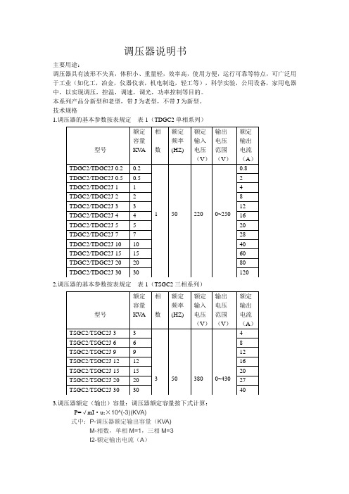
调压器说明书主要用途:调压器具有波形不失真,体积小、重量轻,效率高,使用方便,运行可靠等特点,可广泛用于工业(如化工,冶金,仪器仪表,机电制造,轻工等),科学实验,公用设备,家用电器中,以实现调压,控温,调速,调光,功率控制等目的。
本系列产品分新型和老型,带J为老型,不带J为新型。
技术规格1.调压器的基本参数按表规定表1(TDGC2单相系列)2.调压器的基本参数按表规定表1(TSGC2三相系列)3.调压器额定(输出)容量:调压器额定容量按下式计算:P=√mI·u2×10^(-3)(KVA)式中:P-调压器额定输出容量(KVA)M-相数,单相M=1,三相M=3I2-额定输出电流(A)U2-最大输出电流(V)(三相为线电压)过载(%)不超过(分钟)20 6040 3060 64、调压器绝缘等级为A级,线圈平均温升限值为60℃5、过负荷能力,调压器允许短时间超过额定输出电流值。
但不能超过表2的规定基本原理与主要结构1.基本原理:调压器电刷借助于手轮主轴和刷架的作用,言线圈的磨光表面滑动,变化电刷接触位置、改变一次和二次线圈匝数比,以达到调压的目的。
2、主要结构:①单位结构:单相0.2KV A~10KV A调压器为调压单元结构,一个上端面具有一定宽度的磨光表面的线圈固定在工程塑料的底座上,接触组的电刷在弹簧压力下与线圈的磨光表面金梅接触,转动手轮带动电刷在线圈磨光表面上滑动进行调压。
单元调压器一般为台式,外面有防护通风罩。
单元调压器绕组联接如图一所示:注:图中U1-输入电压(伏)U2-输出电压(伏)D-电刷②单相组装结构,单相大容量调压器是由几个相同规格的单元组装而成,各单元的电刷接触组装在同一主轴上,线圈输入端并联连接平衡电抗器,以平衡单元间电流分布并抑制环流。
单相大容量调压器绕组联接如图2.图3所示:U1-输入电压U2-输出电压D-电刷DK DK1 DK2是平衡电抗器③三相组装结构:三相调压器由三个相同规格的单元同轴组装而成。
低压电子式线路调压器说明书

1.概述电压是电能主要质量指标之一。
电压质量对电网稳定及电力设备安全运行、线路损失、工农业安全生产和人民生活用电都有直接影响。
而实际上,总有一些输电线路过长,线路无功补偿正常功率因数正常的情况下还是会出现末端低电压的情况,因此在线路的中段或者末端,采用电压调节装置就成为必须。
TSVR馈线自动调压器是一种可以自动调节变比来保证输出电压稳定的装置。
TSVR馈线自动调压器可以在线路较低的电压时对线路电压进行自动调节,它特别适用于电压波动大的线路或距离长压降大的线路,将这种调压器串联在馈电线路的中段或者末端,在一定范围内对线路电压进行调整,保证用户的供电电压,也同时可以减少线路的线损。
本产品符合《DL/T375-2010户外配电箱通用技术条件》等电力行业标准。
2.主要特点(1)串联式补偿调压,损耗低,成本合理,体积适中、便于安装维护;(2)跟踪电压变化,自动分相调整各相有载分接开关档位,动作可靠,调节速度快;(3)可以根据需要调整电压基准、动作延时、允许范围,参数设置灵活、方便;(4)显示TSVR输出端电压、电流、功率因数;(5)装置选配一定的电容器,补偿线路无功,降低线路损耗;(6)控制器具有过流、欠压保护,当线路处于过流、欠压状态时,控制器自动闭锁;(7)控制器不仅可以控制调压器的调压功能,还同时可以控制电容器的分相补偿,实现过零投切电容器;(8)控制器采用工业级控制芯片,可靠性高,抗干扰能力强,可适应户外恶劣环境;(9)具有RS485通讯接口,可以通过无线通讯模块在距安装点30m以内查看、修改控制器的参数。
(10)任何异常情况下,都可以快速切换到旁路,确保供电的绝对连续性。
3.产品型号4.环境条件海拔高度:≤2000m环境温度:-30℃~+50℃相对湿度(在25℃时):日平均不大于95%,月平均不大于90%覆冰厚度:≤10mm防护等级:不低于IP43污秽等级:Ⅳ级抗震强度:Ⅷ度安装地点:户外5.运行条件额定电压:AC220V/AC380V额定频率:50Hz安装方式:单杆支架安装6.技术参数及要求6.1技术参数表低压线路电子式调压器性能指标功能综述提高电压合格率补偿线路电压,稳定电压输出,提高电压合格率,配备旁路功能,确保供电可靠性。
Omega PRG 350系列钢铁调压器说明书
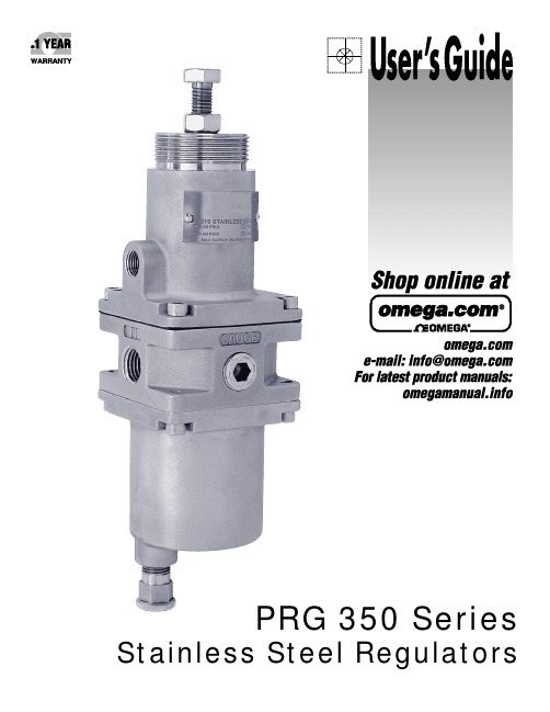
PRG 350 Series Stainless Steel Regulators***********************Servicing North America:U.S.A. Omega Engineering, Inc.Headquarters: Toll-Free: 1-800-826-6342 (USA & Canada only)Customer Service: 1-800-622-2378 (USA & Canada only)Engineering Service: 1-800-872-9436 (USA & Canada only)Tel: (203) 359-1660 Fax: (203) 359-7700**************e-mail:For Other Locations Visit /worldwideThe information contained in this document is believed to be correct, but OMEGA accepts no liability for any errors it contains, and reservesContentsSectionDescription Page 1.0Specifications 22.0Installation 23.0Operation 34.0Maintenance &Repair 35.0Warranty 5Stainless Steel RegulatorsInstallation,Operation andMaintenance Instructions350Bonnet Range Spring*Pintle Assembly*Housing Seal O-Ring *Filter O-Ring (2)Drip Well HousingAssemblyFilter Retainer Spring GuideAdjustment Screw Assembly*DiaphragmAssemblyBody AssemblyCollarFilter,25Micron,SS Filter Retaining ScrewPintle SpringPRG 350SS 1/2"NPT*Included with repair kitRefers to conditions or hazards which could result in serious personal injury or death.Refers to conditions or hazards which could result in personal injury.Refers to conditions or hazards which could result in equipment or property damage.Alerts you to facts or special instructions.ALL DANGER,WARNING,AND CAUTION NOTICES MUST BE COMPLIED WITH IN FULL Personal injury,property damage,equipment damage,or leakage due to escaping gas or bursting ofpressure containing parts may result if this regulator is over pressurized or installed where serviceconditions could exceed the limits given in the specifications.To avoid such injury or damage,providepressure-relieving or limiting devices(as required by the appropriate code,regulation or standard)toprevent service conditions from exceeding those limits.1.Output Ranges:0-30psig(0-2.0BAR),0-60psig(0-4.0BAR),0-100psig(0-7.0BAR),0-150psig(0-10.0BAR)Exhaust Capacity: 1.0SCFM(1.7m3/hr)at downstream pressure of10psig(0.7BAR)above set pointMaximumSupply Pressure:290psig(20.0BAR)Air Consumption:4SCFH(0.1m3/hr)OperatingTemperatures:-20°to+185°F(-29°to+85°C)Filter:25micronPorting:Inlet/Outlet:1/4"NPT or1/2"NPTGauge(2):1/4"NPTExhaust:1/8"NPTMaterials:316stainless steel:body,bonnet,filterFluorocarbon:diaphragm,sealsInconel:range spring,pintle springWeight:1/4"NPT:2.2lbs.(1.0kg)1/2"NPT:2.8lbs.(1.3kg)2.2.1Install the regulator/filter as close as possible to the instrument or tool it is to service.2.2Clean all pipelines to remove dirt and scale prior to installation.Failures attributable to air supply contamination are not covered by the warranty.This instrument vents to atmosphere.The use of gas other than air may create ahazardous environment.2.3Install the regulator/filter so that the direction of flow is from the"IN"to"OUT"connec-tion as marked on the body of the regulator/filter.2.4For best drainage,orient the drain valve so that it is at the lowest point on the drip wellhousing.Positioning of the drain valve may be improved by rotating the drip well with respect to the body.2.5The exhaust port should be kept free and unplugged.Position the regulator so that thevent is at the lowest point possible,or provide additional protection to prevent contami-nants from entering the regulator.Rotating the bonnet relative to the body may change the vent hole orientation.The PRG350Series has a low capacity internal relief that provides limited down stream protectionagainst over pressurization.2.6Exhaust may be remotely vented by installing tubing to the1/8"NPT port.2.7Apply pipe compound or sealing tape to the male pipe threads prior to installingregulator/e caution to prevent the sealant from getting inside the regulator/filter.3.3.1Prior to turning on supply air,back off adjusting screw until there is no compression ofthe range spring.3.2After applying the air supply,output pressure will be increased by rotating the adjust-ment screw clockwise.Pressure can be decreased by turning counter clockwise.3.3Tighten locknut to maintain desired pressure setting.4.4.1To remove condensate from the PRG350Series,slowly open drain valve by turningclockwise and bleed accumulated liquid.To avoid personal injury,property damage,or equipment damage caused by sudden release of pres-sure or explosion of accumulated gas,do not attempt any maintenance or disassembly without firstisolating the regulator from system pressure and relieving all internal pressure from the regulator. 4.2To clean filter element4.2.1Shut off supply pressure and relieve all internal pressure.4.2.2Drain condensate from drip well.4.2.3Remove four corner bolts from bottom of unit and remove drip well housing.4.2.4Remove filter retaining screw.4.2.5Remove filter retainer,filter o-ring seals and filter.4.2.6Clean parts and reassemble in reverse order.4.3To clean/replace pintle assembly4.3.1Follow steps4.2.1through4.2.4.4.3.2Unscrew collar and remove.4.3.3Remove pintle spring and pintle.1/4"NPT version may require needle nose pliers or push pintle stem from above byremoving bonnet and diaphragm assembly.4.3.4Clean/replace parts and reassemble in reverse order.4.4To clean/replace diaphragm assembly4.4.1Back out the adjusting screw until the spring is no longer compressed.4.4.2Remove the four bonnet screws and separate the bonnet from the body of the regulator.Remove the spring guideand spring.4.4.3Remove the diaphragm assembly,clean or replace it as necessary and reassemble in reverse order.After placing thediaphragm assembly on the body,push down the assembly to make sure that the pintle is seated properly andstrokes smoothly.4.5Repair kits/replacement parts4.5.1Repair kits include all parts marked with an asterisk(*).See diagrams on page1.4.5.2When ordering repair kits or replacement filters,order as:REPAIR KITSPRG350Includes:Pintle Assembly,Housing Seal O-Ring,Diaphragm Assembly,Filter Seal O-Ring(2)Model Porting Description Part NumberPRG3541/4”NPT Relieving449-871-068PRG3521/2”NPT Relieving449-871-0704.5.3Other replacement parts are available.Please consult Omega Engineering,Inc.for part numbers and availability.OMEGA’s policy is to make running changes, not model changes, whenever an improvement is possible. This affords our customers the latest in technology and engineering.OMEGA is a registered trademark of OMEGA ENGINEERING, INC.© Copyright 2016 OMEGA ENGINEERING, INC. All rights reserved. T his document may not be copied, photocopied, reproduced, translated, or reduced to any electronic medium or machine-readable form, in whole or in part, without the FOR WARRANTY RETURNS, please have thefollowing information available BEFORE contacting OMEGA:1. P urchase Order number under which the productwas PURCHASED,2. M odel and serial number of the product underwarranty, and3.Repair instructions and/or specific problems relative to the product.FOR NON-WARRANTY REPAIRS, consult OMEGA for current repair charges. Havethe following information available BEFORE contacting OMEGA:1.Purchase Order number to cover the COST of the repair,2.Model and serial number of the product, and 3.Repair instructions and/or specific problems relative to the product.RETURN REQUESTS/INQUIRIESDirect all warranty and repair requests/inquiries to the OMEGA Customer Service Department. BEFORE RET URNING ANY PRODUCT (S) T O OMEGA, PURCHASER MUST OBT AIN AN AUT HORIZED RET URN (AR) NUMBER FROM OMEGA’S CUST OMER SERVICE DEPART MENT (IN ORDER T O AVOID PROCESSING DELAYS). The assigned AR number should then be marked on the outside of the return package and on any correspondence.The purchaser is responsible for shipping charges, freight, insurance and proper packaging to prevent breakage in transit.WARRANTY/DISCLAIMEROMEGA ENGINEERING, INC. warrants this unit to be free of defects in materials and workmanship for a period of 13 months from date of purchase. OMEGA’s WARRANTY adds an additional one (1) month grace period to the normal one (1) year product warranty to cover handling and shipping time. This ensures that OMEGA’s customers receive maximum coverage on each product.If the unit malfunctions, it must be returned to the factory for evaluation. OMEGA’s Customer Service Department will issue an Authorized Return (AR) number immediately upon phone or written request. Upon examination by OMEGA, if the unit is found to be defective, it will be repaired or replaced at no charge. OMEGA’s WARRANT Y does not apply to defects resulting from any action of the purchaser, including but not limited to mishandling, improper interfacing, operation outside of design limits, improper repair, or unauthorized modification. T his WARRANT Y is VOID if the unit shows evidence of having been tampered with or shows evidence of having been damaged as a result of excessive corrosion; or current, heat, moisture or vibration; improper specification; misapplication; misuse or other operating conditions outside of OMEGA’s control. Components in which wear is not warranted, include but are not limited to contact points, fuses, and triacs.OMEGA is pleased to offer suggestions on the use of its various products. However, OMEGA neither assumes responsibility for any omissions or errors nor assumes liability for any damages that result from the use of its products in accordance with information provided by OMEGA, either verbal or written. OMEGA warrants only that the parts manufactured by the company will be as specified and free of defects. OMEGA MAKES NO OTHER WARRANTIES OR REPRESENTATIONS OF ANY KIND WHATSOEVER, EXPRESSED OR IMPLIED, EXCEPT THAT OF TITLE, AND ALL IMPLIED W ARRANTIES INCLUDING ANY W ARRANTY OF MERCHANTABILITY AND FITNESS FOR A PARTICULAR PURPOSE ARE HEREBY DISCLAIMED. LIMITATION OF LIABILITY: The remedies of purchaser set forth herein are exclusive, and the total liability of OMEGA with respect to this order, whether based on contract, warranty, negligence, indemnification, strict liability or otherwise, shall not exceed the purchase price of the component upon which liability is based. In no event shall OMEGA be liable for consequential, incidental or special damages.CONDITIONS: Equipment sold by OMEGA is not intended to be used, nor shall it be used: (1) as a “Basic Component” under 10 CFR 21 (NRC), used in or with any nuclear installation or activity; or (2) in medical applications or used on humans. Should any Product(s) be used in or with any nuclear installation or activity, medical application, used on humans, or misused in any way, OMEGA assumes no responsibility as set forth in our basic WARRANTY /DISCLAIMER language, and, additionally, purchaser will indemnify OMEGA and hold OMEGA harmless from any liability or damage whatsoever arising out of the use of theProduct(s) in such a manner.Where Do I Find Everything I Need for Process Measurement and Control?OMEGA…Of Course!Shop online at SMTEMPERATUREⅪߜThermocouple, RTD & Thermistor Probes, Connectors, Panels & AssembliesⅪߜWire: Thermocouple, RTD & ThermistorⅪߜCalibrators & Ice Point ReferencesⅪߜRecorders, Controllers & Process MonitorsⅪߜInfrared PyrometersPRESSURE, STRAIN AND FORCEⅪߜTransducers & Strain GagesⅪߜLoad Cells & Pressure GagesⅪߜDisplacement TransducersⅪߜInstrumentation & AccessoriesFLOW/LEVELⅪߜRotameters, Gas Mass Flowmeters & Flow ComputersⅪߜAir Velocity IndicatorsⅪߜTurbine/Paddlewheel SystemsⅪߜTotalizers & Batch ControllerspH/CONDUCTIVITYⅪߜpH Electrodes, Testers & AccessoriesⅪߜBenchtop/Laboratory MetersⅪߜControllers, Calibrators, Simulators & PumpsⅪߜIndustrial pH & Conductivity EquipmentDATA ACQUISITIONⅪߜCommunications-Based Acquisition SystemsⅪߜData Logging SystemsⅪߜWireless Sensors, Transmitters, & ReceiversⅪߜSignal ConditionersⅪߜData Acquisition SoftwareHEATERSⅪߜHeating CableⅪߜCartridge & Strip HeatersⅪߜImmersion & Band HeatersⅪߜFlexible HeatersⅪߜLaboratory HeatersENVIRONMENTALMONITORING AND CONTROLⅪߜMetering & Control InstrumentationⅪߜRefractometersⅪߜPumps & TubingⅪߜAir, Soil & Water MonitorsⅪߜIndustrial Water & Wastewater TreatmentⅪߜpH, Conductivity & Dissolved Oxygen Instruments。
SE控制器说明书
智能综合无功补偿控制器
SE-CR05DH-6/9SR
产品使用说明书
1
引言
请您在安装使用本产品之前详细的阅读本手册,以免造成 误操作。
由于产品升级、版本更新,本手册所述内容可能无法完全涵盖。如有错误、遗漏等不当之处, 敬请各位用户谅解。
(二)安装与接线
将控制器装入装置面板开孔(138mm×138mm)内,再将安装卡推进控制器左右侧卡槽内,再 紧固螺钉,将控制器固定在装置面板上。 控制输出为 12V 电平信号+继电器输出
三、因补偿编码方式不同对应控制输出端子接线方式如下:
8
2 组分相 5 路三相补偿: 注:① 因投切器件不同,K1-K11 及 COM 点的接线方式请参照下表:
(四)参数设置
产品有关控制及保护参数,出厂已经预置。如首次使用,用户可根据现场需要对该设备相 关参数进行修改(非常必要)。操作步骤如下:
5
(三)无功补偿功能
取样物理量为无功功率,无投切振荡、无补偿呆区; 具有手动投切和自动投切两种运行方式; 逻辑投切方式,每相电容级数,每组容量自由设定; 控制输出能适应电子开关、交流接触器、复合电子开关或真空接触器等不同投切元件; 控制输出接点 2-12 路、每路 DC12V、60mA 和 AC220V、5A。
(四)保护功能
具有自检复归和自动复位功能; 具有欠压、过压保护功能; 具有谐波超限保护功能。
(五)实时数据通讯功能
具有 RS-485 数据传输接口,支持 MODBUS 通讯协议,通过其与计算机/抄表机连接,可实时 监测电网有关参数、设置参数、工作状态,对预置参数进行修改、并能实现本地或远程各种数 据信息的采集和交换。
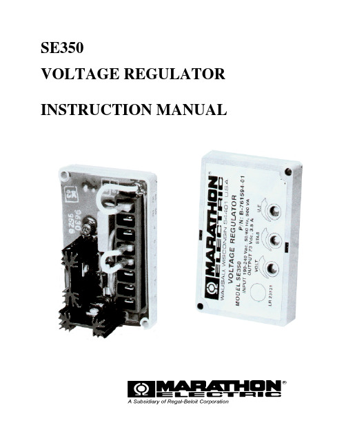
SE350 电压调节器说明书

SE350VOLTAGE REGULATOR INSTRUCTION MANUALINTRODUCTIONThe SE350 voltage regulator is an encapsulated electronic voltage regulator that controls the output of a brushless AC generator by regulating the current into the exciter field. SPECIFICATION SE350 REGULATORSensing & Power Input190-240 VacBurden500 VAOutput Power- Continuous 73 Vdc at 3.5 Adc (255w)Output Power - Forcing(240 Vac Input Power)105 Vdc at 5 Adc (525w)Regulation 1 .0%Remote Voltage Adjustment Range± 10% with 2000 ohm rheostat± 5% with l000 ohm rheostat Frequency Compensation AdjustableRoll off frequency54-61 Hz for 60 Hz45-51 Hz for 50 HzOperation Weight6.5 oz.Operating Temperature- 40°C to + 60°CStorage Temperature- 65°C to + 85°CPower Dissipation8 watts maximumSize 3.94" L X 2.66” W X 2.20: HVoltage Buildup Internal provisions forautomatic voltagebuild up from generator residual voltage aslow as 10 Vac.EMI Suppression Internal Electromagnetic InterferenceFilter (EMI Filter )WARNINGTO PREVENT PERSONAL INJURY OR EQUIPMENTDAMAGEONLY QUALIFIED PERSONNEL SHOULDINSTALL, OPERATE, OR SERVICE THIS DEVICE.CAUTION: DO NOT megger or high-pot the generator with the regulator connected.DO NOT high-pot the regulator.The SE350 voltage regulator can be mounted in any plane, following are mounting dimensions.FIGURE 1FUSEA 4 Amp, 250 V, 5 X 20 mm fuse is supplied with the regulator (Part A-527066).It can be located on the rear face of the voltage regulator.EXCITER POWER CIRCUITConnect the regulator wire F+ to the generator F+ or Fl field terminal.Connect the regulator wire F- to the generator F- or F2 field terminal.See Figure 2 for typical connection diagramSENSING/POWER INPUT CIRCUITInput power and sensing is achieved through terminals 3 and 4.The voltage input requirement of the SE350 is 190 to 240 Vac. See Figure 2FIGURE 2VOLTAGE ADJUSTThe screwdriver adjustable potentiometer adjusts the generator output voltage. Adjustment clockwise increases the generator output voltage.When using a remote voltage adjust rheostat, remove the jumper wire across terminals 6 and 7 and install a 2000 ohm 1/2 watt (minimum) rheostat. This will give ±10% voltage variation from the nominal. (For ±5% voltage variation use a 1000 ohm 1/2 watt rheostat). See Figure 2. STABILITY ADJUSTSystem stability is the ability of the generator to respond to load transients. Decreasing the stability makes the generator less sluggish and faster to respond to toad transients. If the stability of the regulator is decreased too much, the generator will tend to hunt under steady state conditions.The screwdriver adjustable potentiometer adjusts the system stability. Adjustment clockwise increases the stability. Increasing the stability increases the response time of the generator. Conversely, decreasing the stability decreases the response time of the generator.V/HZ ROLL-OFF FREQUENCY SELECTIONThe roll off point is the frequency where the generator voltage starts to decrease. This reduces the Kilowatt load to the engine, which allows the engine to recover in speed under any load transient condition. Use jumper to select 50 HZ or 60 Hz. The screwdriver adjustable potentiometer sets the roll-off frequency from 54-61 Hz in the 60 Hz setting or from 45-51 Hz in the 50 Hz setting.The SE350 has the roll-off point preset to 58 Hz in the 60 Hz mode and 48 Hz in the 50 Hz mode. To change the roll-off point, adjust engine speed to the desired rated speed. (50 or 60 Hz). Set the voltage to the desired setting at rated speed. Adjust engine speed to the desired roll-off point. Turn the potentiometer counterclockwise until the voltage starts to drop off. Then adjust the potentiometer clockwise until the voltage returns to rated voltage. Re-adjust engine speed to rated speed.PRELIMINARY SET-UPEnsure the voltage regulator is correctly connected to the generator. Refer to the specific connection diagram supplied with the generator.Set the regulator voltage adjust to full counter-clockwise (minimum voltage level).Set the remote voltage adjust (if used) to the center position.Set the stability control full clockwise (maximum stability level).Connect the positive lead of a 100 V D.C. voltmeter to Fl and the negative lead of the voltmeter to F2 or use an appropriate AC voltmeter on the generator output leads.SYSTEM START-UPStart and run the generator at no load and rated speed. The generator voltage should build up to a minimum level. (Actual level is dependent upon connection). If it does not build up, refer to field flashing section in generator manual.Slowly adjust the voltage control until the generator voltage reaches the nominal value. If used, adjust the remote voltage rheostat to set the generator voltage to the exact value desired.Turn the stability adjust counter-clockwise until instability is shown on either of the voltmeters mentioned in the “PRELIMINARY SET-UP” section. With the system operating in an unstable condition, slowly adjust the stability control clockwise until generator stability is reached.Interrupt regulator power for a short time (approximately 1-2 seconds).If the generator remains stable, no further adjustment is necessary. If the generator does not remain stable, increase the stability slightly and interrupt regulator power again.This procedure should be repeated until system stability is reached and maintained.TROUBLESHOOTINGSymptom Cause ActionResidual Voltage -No Output Residual voltage at regulator powerinput wires 3 & 4 below 10 V ac.Acceleration time to rated speed toolong.Field leads Fl, F2 not connected.Power input leads not connected.Blown or missing fuse.Defective regulator.Defective generator.Check wiring diagram forproper connections.Flash generator field. Refer tofield flashing section ingenerator manual.Reduce acceleration time.Interrupt power input toregulator after achieving ratedspeed.Connect field leads Fl, F2.Connect power-input leads 3,4.Replace fuse.Replace regulator.Consult generator manual.Output Voltage Low Incorrect connections.Voltages adjust turned down.Remote voltage adjust is turneddown.Defective regulator.Check wiring diagram for proper connections.Rotate voltages adjust CW until desired voltage is reached.Rotate remote voltages adjust CW until desired voltage is reached.Replace regulator.Output Voltage High Voltages adjust turned too high.Remote voltage adjust is turned toohigh.Rotate voltages adjust CCW until desired voltage is reached. Rotate remote voltages adjust CCW until desired voltage is reached.Output Voltage High -No AdjustmentDefective regulator.Replace regulator.Remote Voltage Adjust Operates Backwards Voltages adjust wire backwards.Reverse the wiring of theremote voltage adjust.Generator Output Voltage Hunting Stability adjusts not set properly.Rotate the stability adjusts in aCW direction until huntingstops.Poor Regulation Defective regulator.Replace regulator.。
Edge 2.0高容量调压器说明书

MEET EDGE 2 As someone who never settles for good enough, you deserve a regulator that’s as tough as you, as sharpas you, as good as you. And it has arrived. It’s EDGE 2.0. INNOVATION.Drastically different gaugesRearranged for the better PERFORMANCE.Rugged diaphragmSuperior flowReassuring warrantySAFETY.For more than 100 years, Victor has kept a commitment to developing uncompromising safety features, and EDGE 2.0 continues to deliver onthat promise.Impact-absorbing knob – The tactile knob on EDGE 2.0 is supported by SLAM™ (Shock L imitation and Absorption Mechanism) technology that protectsthe regulator with a three-stage crumple system. Purposeful outlet positioning – The outlet points down on EDGE 2.0, out the rear of the regulator –a safer placement because it shifts the hose-related hazards away from the user.Internal particle trap – T wo elements – the primary particle trap and the secondary diffuser – minimizethe amount of contaminant energy that reaches the seat, significantly reducing the chance of an explosion or a fire.Visual safety – Crucial specs are communicated clearly with color-coding, gas-specific labeling, and symbols, making it easier to understand critical information from a distance or at a glance.Proven by trialEASE OF USE.Simpler. More intuitive. Easier to operate. EDGE 2.0 takes the guesswork out of gas control.Improved accessibility – EDGE 2.0 has a significantly wider cylinder valve clearance for easier and quicker connecting and disconnecting.T actile adjustment knob – The updated knob design is easier to grip and points away from the userfor a more natural hand/body position, which clears the way for a better view of the gauges.Intuitive gauges – The extra-large, offset 2.5-inch delivery gauge is easy to read and provides more information than the average regulator, taking out any guesswork.NOW MEET THE PLUS SERIES TORCH AND HANDLE . JOURNEYMAN OUTFIT. The robust Journeyman outfit comes with everything you need to get started: CA 2460+ cutting attachment, WH 315FC+ welding handle, cutting tip, tip cleaner, heating nozzle, striker, goggles, hose, welding nozzles, and two EDGE 2.0 regulators.The CA 2460+ cutting attachment and WH 315FC+welding handle are also newly available and vastlyimproved, thanks in large part to input from talentedand insightful craftsmen who use our tools daily.Advanced flashback arrestor – We challengedourselves to design a torch that has the built-infeatures we love but none of those all-too-commonflow restrictions, and that’s what we delivered.More communicative valves – Understanding thatnot everyone in the industry has the same level ofcomfort and familiarity with a torch, we added smalllabels – open/close, on/off, oxy/fuel – to help guidemore-novice users.Improved field reparability – The user-friendlydesign of the Plus Series allows for immediatereplacement of the plunger and easy access tothe mixer.Glove-friendly knobs – Upgraded contouring makesfor easier use with gloved hands.Ergonomic handling – The curved lever can betriggered with the palm or the thumb and supportsmore-relaxed feathering.T ougher where it counts – When we watchedcraftsmen work, we saw they use their torchesas hammers and scrapers, so we reinforced themost-used areas with additional materials toincrease longevity.REGULATOR PART NUMBERSPart NumberDescription 0781-3600ESS42-60-540 S/S OXY 60 psig 0781-3601ESS42-150-540 S/S OXY 150 psig 0781-3602ESS42-15-510 S/S ACET 15 psig 0781-3603ESS42-15-300 S/S ACET 15 psig 0781-3605ESS42-15-410 S/S ACET 15 psig 0781-3606ESS42-60-510LP S/S LPG 60 psig 0781-3607ESS42-150-510LP S/S LPG 150 psig 0781-3609ESS42-150-580 S/S INERT 150 psig 0781-3612ESS42-150-350 S/S HYD 150 psig 0781-3613ESS42-150-346 S/S AIR 150 psig 0781-3614ESS42-150-590 S/S IndAir 150 psig 0781-3615ESS42-150-320 S/S CO 2150 psig EDGE 2.0 GAS OPTIONS. Acetylene // Oxygen // Carbon dioxide Nitrogen inert gas // Propane LP gas Air // Hydrogen/Methane OUTFIT PART NUMBERS Part Number Description 0384-2081Journeyman Sel EDGE 2.0 540/510, 90° PLUS OUTFIT 0384-2082Journeyman Sel EDGE 2.0 540/510, 75° PLUS OUTFIT 0384-2083Journeyman Sel EDGE 2.0 540/300, 90° PLUS OUTFIT 0384-2088Journeyman Sel AF EDGE 2.0 540/510LP , 90° PLUS OUTFIT 0384-2100Journeyman EDGE 2.0 540/300, 90° PLUS OUTFIT 0384-2101Journeyman EDGE 2.0 540/510, 90° PLUS OUTFIT 0384-2110Journeyman II EDGE 2.0 540/300, 90° PLUS OUTFIT 0384-2111Journeyman II EDGE 2.0 540/510, 90° PLUS OUTFIT 0384-2112Journeyman II AF EDGE 2.0 540/510LP , 90° PLUS OUTFIT(Propane)0384-2113Journeyman II AF EDGE 2.0540/510LP , 90° PLUS OUTFIT(Propylene)0384-2120Cutter EDGE 2.0 540/510, 90°ST2600FC OUTFIT0384-2121Cutter EDGE 2.0 540/300, 90°ST2600FC OUTFIT0384-2122Cutter AF EDGE 2.0 540/510LP , 90°ST2600FC OUTFIT0381-1928CA2460+ Cutting Attach, 90°0381-1930CA2461+ Cutting Attach, 75°0381-1932CA2462+ Cutting Attach, 180°0381-1937CA2460+/WH315FC+ Repl Pack, 90°0382-0093WH315FC+ Weld Handle Note: Part numbers have recently changed.Please update your records with the above information.5-YEAR WARRANTY.5/。
调压柜(箱)使用说明书
通过ISO9001:2000质量管理体系认证企业燃气调压柜(站)使用说明书*************************目录一、概述二、特点三、调压柜(站)类型四、调压柜(站)工艺流程五、调压柜(箱)主要型号技术参数六、调压柜(站)安装和使用七、调压柜(站)维护八、调压柜(站)常见故障处理九、注意事项十、订货须知十一、附件和配件十二、售后服务本资料所介绍的燃气调压柜(站)是按最常采用的输配工艺布置,仅供用户在选型时参考。
更多的是根据用户提供的参数及选配的设备来设计生产。
本公司提供的各种调压柜(站)的技术参数仅供参考。
一、概述基本功能◆燃气净化:对燃气进行过滤,以保证系统内设备正常工作。
◆燃气调压:将上游管网的燃气压力降至下游管网或管道所需的使用压力,并保持在规定的范围内,且不随上游压力和流量的变化而变化。
◆安全保护:当下游压力因故超过系统规定的压力范围时,对下游气流进行控制或对上游气流进行截流,以保证安全用气。
◆流量计量:对燃气流量进行测量并换算为标准状态下的流量。
可扩展功能◆自控系统:对运行状况进行遥测遥讯遥控。
◆报警系统:对泄漏、故障进行报警。
◆加臭装置:将溴液加入燃气中使之具有臭味。
◆伴热装置:对管壁进行加热给燃气保温。
◆热交换装置:对燃气加热使之不结冰。
二、特点◆集调压、过滤、超压/失压切断、计量、安全放散等为一体,系统协调性好、可靠性高。
◆结构紧凑,造型美观,占地面积及所要求的安全距离小。
适合户内、外安装。
◆安装、调试简单,使用、维护方便。
◆适用于天然气、人工煤气、石油液化气及其它无腐蚀性气体。
◆扩展性好,可根据用户要求增添功能。
◆设备出厂前均经24h气密性试验。
各参数均按用户要求设定,现场操作简单、方便。
◆箱体材料均采用高强度复合板,利用先进的技术批量生产,保证同型号箱体零件的互换性。
外箱内外表面采用彩板,防腐能力强。
◆可无人值守,只需定期检查。
三、调压柜(站)类型●按用户类型分为:首站、门站、高中压调压站、民用区域调压柜、锅炉专用。
久安SE系列调压器使用说明书
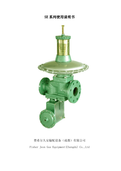
安装 1. ............................................................................................................................................................... 10 使用 2. ................................................................................................................................................................11
3. SE65................................................................................................................................................................ 8
L
D
L1
H1
H2
H3
SE40
248 330/436
90 715
550
177/183
SE50
330 330/436
120 895
580
207/213
SE65
350 436/510
130 895/930
565/600
200/205
SE80
400 436/510/610 150 915/950/955 585/620/625 216/223/226
SE 系列说明书 080320
SE350中文说明书

SE350发电机自动调压板使用手册版本 1.0日期:2015/06/27SE350版本历史记录:日期版本内容2015-06-27 1.0首次发行目录2.技术参数 (3)3.尺寸图 (4)4.接线 (5)3.1.励磁场接线“+、一” (5)3.2.检测&电源输入“3、4” (5)3.3.外接电压调节器“6、7” (5)3.4.低频保护一频率选择“50/60” (5)5.操作说明 (6)6.测试图: (8)1.技术参数项目参数说明电源检测输入电压85-135VAC/190-r240VAC单相频率50/60Hz以跨接线设定电压选择指拨开关选择120/240VAC输出电压120VAC输入时最大36VDC240VAC输入时最大73VDC电流连续4A非连续为10秒内7A(52/105VDC)电阻最小15Ohm最大100Ohm电压建立在AV R输入端子需剩磁电压5VAC以上,25Hz EMI抑制内建与突波吸收器与滤波器调压精度<士1%(发动机转速变动在4%内)外部电压调节用1K Ohms1Watt电位器时为士5%用2K Ohms1Watt电位器时为士10%消耗功率最大8Watt低频保护50Hz系统转折点为45-51Hz60Hz系统转折点为54-61Hz(*拐点值为出厂设定值)尺寸99.5mm L*67mm W*47.5mm H重量0.3KG2.尺寸图图一3.接线3.1.励磁场接线“+、一”(1)将调压板上注“F+”之引线连接于励磁机磁场“+”,将注“F-”引线连接至磁场“一”。
注:励磁机磁场直流电阻为15-100Ω。
(2)如果磁场电阻小于15Ω且在发电机全载时,磁场电压小于70V DC时可串接一适当瓦数(W)的电阻,使磁场总电阻为15一100Ω。
3.2.检测&电源输入“3、4”调压板上注“3、4”引线接至发电机组绕组,可由电压选择开关选择120或240VAC系统。
3.3.外接电压调节器“6、7”(1)调压板内部提供一发电机电压粗调预设旋钮(VOLT),顺时针方向增加。
LM350系列可调电压调节器说明书
3-Amp Adjustable RegulatorsIn addition to higher performance than fixed FEATURESregulators,the LM350series offers full overload •Adjustable Output Down to 1.2V protection available only in IC's.Included on the chip •Guaranteed 3A output Current are current limit,thermal overload protection and safe area protection.All overload protection circuitry •Guaranteed Thermal Regulation remains fully functional even if the adjustment •Output is Short Circuit Protectedterminal is accidentally disconnected.•Current Limit Constant with Temperature Normally,no capacitors are needed unless the device •P +Product Enhancement Tested is situated more than 6inches from the input filter •86dB Ripple Rejectioncapacitors in which case an input bypass is needed.An output capacitor can be added to improve •Ensured 1%Output Voltage Tolerance transient response,while bypassing the adjustment (LM350A)pin will increase the regulator's ripple rejection.•Ensured Max.0.01%/V Line Regulation Besides replacing fixed regulators or discrete (LM350A)designs,the LM350is useful in a wide variety of •Ensured Max.0.3%Load Regulation (LM350A)other applications.Since the regulator is “floating”and sees only the input-to-output differential voltage,APPLICATIONSsupplies of several hundred volts can be regulated as long as the maximum input to output differential is not •Adjustable Power supplies exceeded,i.e.,avoid short-circuiting the output.•Constant Current Regulators By connecting a fixed resistor between the •Battery Chargersadjustment pin and output,the LM350can be used as a precision current regulator.Supplies with DESCRIPTIONelectronic shutdown can be achieved by clamping the The LM350series of adjustable 3-terminal positive adjustment terminal to ground which programs the voltage regulators is capable of supplying in excess output to 1.2V where most loads draw little current.of 3A over a 1.2V to 33V output range.They are exceptionally easy to use and require only 2external resistors to set the output voltage.Further,both line and load regulation are comparable to discrete designs.Also,the LM350is packaged in standard transistor packages which are easily mounted and handled.Connection DiagramCase is OutputFigure 1.(TO-3STEEL)Metal Can PackageFigure 2.(TO-220)Plastic PackageBottom View Front ViewAbsolute Maximum RatingsPower Dissipation Internally Limited Input-Output Voltage Differential+35V Storage Temperature−65°C to+150°CMetal Package(Soldering,10sec.)300°C Lead TemperaturePlastic Package(Soldering,4sec.)260°C ESD Tolerance TBDOperating Temperature Range LM350A−40°C≤T J≤+125°C LM3500°C≤T J≤+125°CElectrical CharacteristicsSpecifications with standard type face are for T J=25°C,and those with boldface type apply over full Operating Temperature Range.Unless otherwise specified,V IN−V OUT=5V,and I OUT=10mA.LM350A LM350Units Parameter ConditionsMin Typ Max Min Typ MaxI OUT=10mA,T J=25°C 1.238 1.250 1.262V Reference Voltage3V≤(V IN−V OUT)≤35V,1.225 1.250 1.270 1.20 1.25 1.30V10mA≤I OUT≤3A,P≤30W0.0050.010.0050.03%/V Line Regulation3V≤(V IN−V OUT)≤35V0.020.050.020.07%/V0.10.30.10.5% Load Regulation10mA≤I OUT≤3A0.310.3 1.5% Thermal Regulation20ms Pulse0.0020.010.0020.03%/W Adjustment Pin Current5010050100μA Adjustment Pin Current Change10mA≤I OUT≤3A,3V≤(V IN−V OUT)≤35V0.250.25μA Temperature Stability T MIN≤T J≤T MAX11% Minimum Load Current V IN−V OUT=35V 3.510 3.510mAV IN−V OUT≤10V 3.0 4.5 3.0 4.5A Current LimitV IN−V OUT=30V0.310.251A RMS Output Noise,%of V OUT10Hz≤f≤10kHz0.0010.001%V OUT=10V,f=120Hz,C ADJ=0μF6565dB Ripple Rejection RatioV OUT=10V,f=120Hz,C ADJ=10μF66866686dB Long-Term Stability T J=125°C,1000hrs0.2510.251%NDS Package 1.2 1.5°C/W Thermal Resistance,Junction toCase NDE Package3434°C/WNDS Package35°C/W Thermal Resistance,Junction toAmbient(No Heat Sink)NDE Package5050°C/WImportant statement:Huaguan Semiconductor Co,Ltd.reserves the right to change the products and services provided without notice.Customers should obtain the latest relevant information before ordering, and verify the timeliness and accuracy of this information. Customers are responsible for complying with safety standards and taking safety measures when using our products for system design and machine manufacturing to avoid potential risks that may result in personal injury or property damage.Our products are not licensed for applications in life support, military,aerospace,etc.,so we do not bear the consequences of the application of these products in these fields.Our documentation is only permitted to be copied without any tampering with the content,so we do not accept any responsibility or liability for the altered documents.。
马拉松电机SE350调压说明书

输出电压高不能调节
调压器故障
更换调压器
遥控电压调节反向
电压调节线反向
部遥控电压调节的线反一下
发电机输出电压震荡
稳定性调节整定不适
顺时针方向旋转稳定调节电位器直到震荡停止
调节率差
调节器故障
更换调压器
马拉松发电机SE350调压器
调压器故障处理方法
故障
原因
处理方法
剩磁电压无输出
调压器电源输入端3和4上剩磁低于10V
额定转速加速时间太长
磁场引线F+、F-没有连接(F+红线F-黑线)
电源输入引线没有接
保险丝爆断或没有保险丝
调压机说明书、磁场充磁
减少加速时间
在达到额定转速后中断调压器电源输入
连接磁场引线F+、F—(F+红线F-黑线)
连接电源输出引线
更换保险丝
更换调压版
参照发电机说明书
输出电压低
接线错误
电压调节太低
遥控电压调节太低
调压器调节故障
按接线图检查接线
顺时针调节电压电位器直到所有要求电压
顺时针调节遥控电压电位器直到所有要求电压
更换调压器
输出电压高
电压调节太高
遥控电压调节太低
逆时针转动调节电位器直直到所要求电压
马拉松SE350调压器说明书
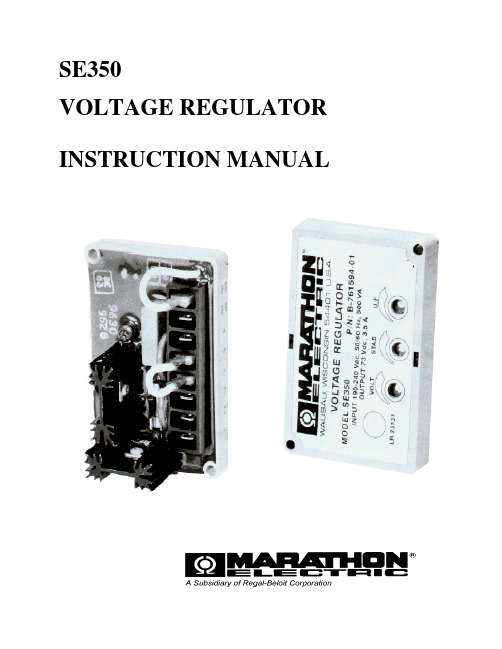
SE350VOLTAGE REGULATOR INSTRUCTION MANUALINTRODUCTIONThe SE350 voltage regulator is an encapsulated electronic voltage regulator that controls the output of a brushless AC generator by regulating the current into the exciter field. SPECIFICATION SE350 REGULATORSensing & Power Input190-240 VacBurden500 VAOutput Power- Continuous 73 Vdc at 3.5 Adc (255w)Output Power - Forcing(240 Vac Input Power)105 Vdc at 5 Adc (525w)Regulation 1 .0%Remote Voltage Adjustment Range± 10% with 2000 ohm rheostat± 5% with l000 ohm rheostat Frequency Compensation AdjustableRoll off frequency54-61 Hz for 60 Hz45-51 Hz for 50 HzOperation Weight6.5 oz.Operating Temperature- 40°C to + 60°CStorage Temperature- 65°C to + 85°CPower Dissipation8 watts maximumSize 3.94" L X 2.66” W X 2.20: HVoltage Buildup Internal provisions forautomatic voltagebuild up from generator residual voltage aslow as 10 Vac.EMI Suppression Internal Electromagnetic InterferenceFilter (EMI Filter )WARNINGTO PREVENT PERSONAL INJURY OR EQUIPMENTDAMAGEONLY QUALIFIED PERSONNEL SHOULDINSTALL, OPERATE, OR SERVICE THIS DEVICE.CAUTION: DO NOT megger or high-pot the generator with the regulator connected.DO NOT high-pot the regulator.The SE350 voltage regulator can be mounted in any plane, following are mounting dimensions.FIGURE 1FUSEA 4 Amp, 250 V, 5 X 20 mm fuse is supplied with the regulator (Part A-527066).It can be located on the rear face of the voltage regulator.EXCITER POWER CIRCUITConnect the regulator wire F+ to the generator F+ or Fl field terminal.Connect the regulator wire F- to the generator F- or F2 field terminal.See Figure 2 for typical connection diagramSENSING/POWER INPUT CIRCUITInput power and sensing is achieved through terminals 3 and 4.The voltage input requirement of the SE350 is 190 to 240 Vac. See Figure 2FIGURE 2VOLTAGE ADJUSTThe screwdriver adjustable potentiometer adjusts the generator output voltage. Adjustment clockwise increases the generator output voltage.When using a remote voltage adjust rheostat, remove the jumper wire across terminals 6 and 7 and install a 2000 ohm 1/2 watt (minimum) rheostat. This will give ±10% voltage variation from the nominal. (For ±5% voltage variation use a 1000 ohm 1/2 watt rheostat). See Figure 2. STABILITY ADJUSTSystem stability is the ability of the generator to respond to load transients. Decreasing the stability makes the generator less sluggish and faster to respond to toad transients. If the stability of the regulator is decreased too much, the generator will tend to hunt under steady state conditions.The screwdriver adjustable potentiometer adjusts the system stability. Adjustment clockwise increases the stability. Increasing the stability increases the response time of the generator. Conversely, decreasing the stability decreases the response time of the generator.V/HZ ROLL-OFF FREQUENCY SELECTIONThe roll off point is the frequency where the generator voltage starts to decrease. This reduces the Kilowatt load to the engine, which allows the engine to recover in speed under any load transient condition. Use jumper to select 50 HZ or 60 Hz. The screwdriver adjustable potentiometer sets the roll-off frequency from 54-61 Hz in the 60 Hz setting or from 45-51 Hz in the 50 Hz setting.The SE350 has the roll-off point preset to 58 Hz in the 60 Hz mode and 48 Hz in the 50 Hz mode. To change the roll-off point, adjust engine speed to the desired rated speed. (50 or 60 Hz). Set the voltage to the desired setting at rated speed. Adjust engine speed to the desired roll-off point. Turn the potentiometer counterclockwise until the voltage starts to drop off. Then adjust the potentiometer clockwise until the voltage returns to rated voltage. Re-adjust engine speed to rated speed.PRELIMINARY SET-UPEnsure the voltage regulator is correctly connected to the generator. Refer to the specific connection diagram supplied with the generator.Set the regulator voltage adjust to full counter-clockwise (minimum voltage level).Set the remote voltage adjust (if used) to the center position.Set the stability control full clockwise (maximum stability level).Connect the positive lead of a 100 V D.C. voltmeter to Fl and the negative lead of the voltmeter to F2 or use an appropriate AC voltmeter on the generator output leads.SYSTEM START-UPStart and run the generator at no load and rated speed. The generator voltage should build up to a minimum level. (Actual level is dependent upon connection). If it does not build up, refer to field flashing section in generator manual.Slowly adjust the voltage control until the generator voltage reaches the nominal value. If used, adjust the remote voltage rheostat to set the generator voltage to the exact value desired.Turn the stability adjust counter-clockwise until instability is shown on either of the voltmeters mentioned in the “PRELIMINARY SET-UP” section. With the system operating in an unstable condition, slowly adjust the stability control clockwise until generator stability is reached.Interrupt regulator power for a short time (approximately 1-2 seconds).If the generator remains stable, no further adjustment is necessary. If the generator does not remain stable, increase the stability slightly and interrupt regulator power again.This procedure should be repeated until system stability is reached and maintained.TROUBLESHOOTINGSymptom Cause ActionResidual Voltage -No Output Residual voltage at regulator powerinput wires 3 & 4 below 10 V ac.Acceleration time to rated speed toolong.Field leads Fl, F2 not connected.Power input leads not connected.Blown or missing fuse.Defective regulator.Defective generator.Check wiring diagram forproper connections.Flash generator field. Refer tofield flashing section ingenerator manual.Reduce acceleration time.Interrupt power input toregulator after achieving ratedspeed.Connect field leads Fl, F2.Connect power-input leads 3,4.Replace fuse.Replace regulator.Consult generator manual.Output Voltage Low Incorrect connections.Voltages adjust turned down.Remote voltage adjust is turneddown.Defective regulator.Check wiring diagram for proper connections.Rotate voltages adjust CW until desired voltage is reached.Rotate remote voltages adjust CW until desired voltage is reached.Replace regulator.Output Voltage High Voltages adjust turned too high.Remote voltage adjust is turned toohigh.Rotate voltages adjust CCW until desired voltage is reached. Rotate remote voltages adjust CCW until desired voltage is reached.Output Voltage High -No AdjustmentDefective regulator.Replace regulator.Remote Voltage Adjust Operates Backwards Voltages adjust wire backwards.Reverse the wiring of theremote voltage adjust.Generator Output Voltage Hunting Stability adjusts not set properly.Rotate the stability adjusts in aCW direction until huntingstops.Poor Regulation Defective regulator.Replace regulator.。
调压器说明书

调压器说明书主要用途:调压器具有波形不失真,体积小、重量轻,效率高,使用方便,运行可靠等特点,可广泛用于工业(如化工,冶金,仪器仪表,机电制造,轻工等),科学实验,公用设备,家用电器中,以实现调压,控温,调速,调光,功率控制等目的。
本系列产品分新型和老型,带J为老型,不带J为新型。
技术规格1.调压器的基本参数按表规定表1(TDGC2单相系列)2.调压器的基本参数按表规定表1(TSGC2三相系列)3.调压器额定(输出)容量:调压器额定容量按下式计算:P=√mI·u2×10^(-3)(KVA)式中:P-调压器额定输出容量(KVA)M-相数,单相M=1,三相M=3I2-额定输出电流(A)U2-最大输出电流(V)(三相为线电压)过载(%)不超过(分钟)20 6040 3060 64、调压器绝缘等级为A级,线圈平均温升限值为60℃5、过负荷能力,调压器允许短时间超过额定输出电流值。
但不能超过表2的规定基本原理与主要结构1.基本原理:调压器电刷借助于手轮主轴和刷架的作用,言线圈的磨光表面滑动,变化电刷接触位置、改变一次和二次线圈匝数比,以达到调压的目的。
2、主要结构:①单位结构:单相0.2KV A~10KV A调压器为调压单元结构,一个上端面具有一定宽度的磨光表面的线圈固定在工程塑料的底座上,接触组的电刷在弹簧压力下与线圈的磨光表面金梅接触,转动手轮带动电刷在线圈磨光表面上滑动进行调压。
单元调压器一般为台式,外面有防护通风罩。
单元调压器绕组联接如图一所示:注:图中U1-输入电压(伏)U2-输出电压(伏)D-电刷②单相组装结构,单相大容量调压器是由几个相同规格的单元组装而成,各单元的电刷接触组装在同一主轴上,线圈输入端并联连接平衡电抗器,以平衡单元间电流分布并抑制环流。
单相大容量调压器绕组联接如图2.图3所示:U1-输入电压U2-输出电压D-电刷DK DK1 DK2是平衡电抗器③三相组装结构:三相调压器由三个相同规格的单元同轴组装而成。
SE350AVR说明书
SE350VOLTAGE REGULATOR INSTRUCTION MANUALINTRODUCTIONThe SE350 voltage regulator is an encapsulated electronic voltage regulator that controls the output of a brushless AC generator by regulating the current into the exciter field. SPECIFICATION SE350 REGULATORSensing & Power Input190-240 VacBurden500 VAOutput Power- Continuous 73 Vdc at 3.5 Adc (255w)Output Power - Forcing(240 Vac Input Power)105 Vdc at 5 Adc (525w)Regulation 1 .0%Remote Voltage Adjustment Range± 10% with 2000 ohm rheostat± 5% with l000 ohm rheostat Frequency Compensation AdjustableRoll off frequency54-61 Hz for 60 Hz45-51 Hz for 50 HzOperation Weight6.5 oz.Operating Temperature- 40°C to + 60°CStorage Temperature- 65°C to + 85°CPower Dissipation8 watts maximumSize 3.94" L X 2.66” W X 2.20: HVoltage Buildup Internal provisions forautomatic voltagebuild up from generator residual voltage aslow as 10 Vac.EMI Suppression Internal Electromagnetic InterferenceFilter (EMI Filter )WARNINGTO PREVENT PERSONAL INJURY OR EQUIPMENTDAMAGEONLY QUALIFIED PERSONNEL SHOULDINSTALL, OPERATE, OR SERVICE THIS DEVICE.CAUTION: DO NOT megger or high-pot the generator with the regulator connected.DO NOT high-pot the regulator.The SE350 voltage regulator can be mounted in any plane, following are mounting dimensions.FIGURE 1FUSEA 4 Amp, 250 V, 5 X 20 mm fuse is supplied with the regulator (Part A-527066).It can be located on the rear face of the voltage regulator.EXCITER POWER CIRCUITConnect the regulator wire F+ to the generator F+ or Fl field terminal.Connect the regulator wire F- to the generator F- or F2 field terminal.See Figure 2 for typical connection diagramSENSING/POWER INPUT CIRCUITInput power and sensing is achieved through terminals 3 and 4.The voltage input requirement of the SE350 is 190 to 240 Vac. See Figure 2FIGURE 2VOLTAGE ADJUSTThe screwdriver adjustable potentiometer adjusts the generator output voltage. Adjustment clockwise increases the generator output voltage.When using a remote voltage adjust rheostat, remove the jumper wire across terminals 6 and 7 and install a 2000 ohm 1/2 watt (minimum) rheostat. This will give ±10% voltage variation from the nominal. (For ±5% voltage variation use a 1000 ohm 1/2 watt rheostat). See Figure 2. STABILITY ADJUSTSystem stability is the ability of the generator to respond to load transients. Decreasing the stability makes the generator less sluggish and faster to respond to toad transients. If the stability of the regulator is decreased too much, the generator will tend to hunt under steady state conditions.The screwdriver adjustable potentiometer adjusts the system stability. Adjustment clockwise increases the stability. Increasing the stability increases the response time of the generator. Conversely, decreasing the stability decreases the response time of the generator.V/HZ ROLL-OFF FREQUENCY SELECTIONThe roll off point is the frequency where the generator voltage starts to decrease. This reduces the Kilowatt load to the engine, which allows the engine to recover in speed under any load transient condition. Use jumper to select 50 HZ or 60 Hz. The screwdriver adjustable potentiometer sets the roll-off frequency from 54-61 Hz in the 60 Hz setting or from 45-51 Hz in the 50 Hz setting.The SE350 has the roll-off point preset to 58 Hz in the 60 Hz mode and 48 Hz in the 50 Hz mode. To change the roll-off point, adjust engine speed to the desired rated speed. (50 or 60 Hz). Set the voltage to the desired setting at rated speed. Adjust engine speed to the desired roll-off point. Turn the potentiometer counterclockwise until the voltage starts to drop off. Then adjust the potentiometer clockwise until the voltage returns to rated voltage. Re-adjust engine speed to rated speed.PRELIMINARY SET-UPEnsure the voltage regulator is correctly connected to the generator. Refer to the specific connection diagram supplied with the generator.Set the regulator voltage adjust to full counter-clockwise (minimum voltage level).Set the remote voltage adjust (if used) to the center position.Set the stability control full clockwise (maximum stability level).Connect the positive lead of a 100 V D.C. voltmeter to Fl and the negative lead of the voltmeter to F2 or use an appropriate AC voltmeter on the generator output leads.SYSTEM START-UPStart and run the generator at no load and rated speed. The generator voltage should build up to a minimum level. (Actual level is dependent upon connection). If it does not build up, refer to field flashing section in generator manual.Slowly adjust the voltage control until the generator voltage reaches the nominal value. If used, adjust the remote voltage rheostat to set the generator voltage to the exact value desired.Turn the stability adjust counter-clockwise until instability is shown on either of the voltmeters mentioned in the “PRELIMINARY SET-UP” section. With the system operating in an unstable condition, slowly adjust the stability control clockwise until generator stability is reached.Interrupt regulator power for a short time (approximately 1-2 seconds).If the generator remains stable, no further adjustment is necessary. If the generator does not remain stable, increase the stability slightly and interrupt regulator power again.This procedure should be repeated until system stability is reached and maintained.TROUBLESHOOTINGSymptom Cause ActionResidual Voltage -No Output Residual voltage at regulator powerinput wires 3 & 4 below 10 V ac.Acceleration time to rated speed toolong.Field leads Fl, F2 not connected.Power input leads not connected.Blown or missing fuse.Defective regulator.Defective generator.Check wiring diagram forproper connections.Flash generator field. Refer tofield flashing section ingenerator manual.Reduce acceleration time.Interrupt power input toregulator after achieving ratedspeed.Connect field leads Fl, F2.Connect power-input leads 3,4.Replace fuse.Replace regulator.Consult generator manual.Output Voltage Low Incorrect connections.Voltages adjust turned down.Remote voltage adjust is turneddown.Defective regulator.Check wiring diagram for proper connections.Rotate voltages adjust CW until desired voltage is reached.Rotate remote voltages adjust CW until desired voltage is reached.Replace regulator.Output Voltage High Voltages adjust turned too high.Remote voltage adjust is turned toohigh.Rotate voltages adjust CCW until desired voltage is reached. Rotate remote voltages adjust CCW until desired voltage is reached.Output Voltage High -No AdjustmentDefective regulator.Replace regulator.Remote Voltage Adjust Operates Backwards Voltages adjust wire backwards.Reverse the wiring of theremote voltage adjust.Generator Output Voltage Hunting Stability adjusts not set properly.Rotate the stability adjusts in aCW direction until huntingstops.Poor Regulation Defective regulator.Replace regulator.。
SE350套管升降器 蛛网操作手册说明书

SE350CASING ELEVATOR/SPIDER OPERATION MANUALSE350-SMGoldenman Petroleum Equipment Co., Ltd Add:7/F, Wanda International Mansion, 67 Fuqian Street , Dongying ChinaTel:+0086-546-8058779 E-mail:********************CONTENTS1. PRODUCT INTRODUCTION2. MAIN TECHNICAL PARAMETERS3. MAIN PARTS STRUCTURE AND WORKING PRINCIPLE4. INSTALLATION5. OPERATION INSTRUCTIONS6. LUBRICATION7. MAINTENANCE8. TROUBLE SHOOTING1. Product IntroductionSE350 casing elevator/spider is a kind of pneumatically operated well head tools, applicable for onshore and offshore casing operation. It can handle casing ranging from 4” to 14”. By operating the reversing air valve may bring slips up or down to clamp or release casing. Meanwhile, the lock device on control valve may lock slips safely.SE500 casing elevator/spider can be used alone as a spider, or as an elevator. The elevator is fitted with a bell guide and bottom guide. The spider is fitted with a top guide that centers the spider over the master bushing. (Fig. 1) The elevator is attached to the derrick traveling block and hook with 350 ton standard API links. The Spider locates directly on the pin drive master bushing (27 1/2 MSPC, 37 1/2 and 49 1/2 MPCH), and square drive master bushing (27 1/2 MSS), and will accommodate any other master bushing when used with an Adapter Plate.Fig.12. Technical Parameters2.1 Applicable casing OD 101.6-355.6mm (4-14in)2.2 Load capacity 3150kN 2.3 Air pressure 0.6-0.8MPa 2.4 Dimensions of elevator 1080*1052*986mm 2.5 Dimensions of spider1080*1052*764mmFig.22.6 Weight of elevator 2473 kg (with one slip assembly)2.7 Weight of spider2383kg (with one slip assembly)2.8 Design and lowest working temperature -20℃2.9 Refer to the following table 1 for Specification of slip assemblies,inserts, bell guides, and top guides.Table 1:InsertsElevatorSpiderCasing Size(in)Slip Body SizeInsertsNumberBeveled InsertsNumberBell Guide Top Guide 424164.1/2216824 2168B 164-4.1/24-4.1/25216924 2169B16555.1/2 2170405.3/45.1/2405.1/2-5.3/45.1/2-5.3/4Inserts Elevator Spider Casing Size(in)Slip Body SizeInsertsNumbe r Beveled Inserts Inserts6.5/82632362632B 2472623362623B 246.5/8-777.5/82633607.3/47.5/82649-1607.5/8-7.3/47.5/8-7.3/48.5/82640482640B 328.3/42650482650B 328.5/8-8.3/48.5/8-8.3/49.5/82633809.5/89.5/89.3/42649-1809.7/89.5/82649-1809.3/4-9.7/89.3/4-9.7/810.3/42640602640B 4010.7/82650602650B 4010.3/4-10.7/810.3/4-10.7/811.3/4263710011.7/811.3/4265110011.3/4-11.7/811.3/4-11.7/812.3/42657602657B 4012.3/412.3/413.3/82636602636B 4013.3/813.3/813.1/22652602652B 4013.5/82653602653B 4013.3/42655602655B 4013.1/2-13.3/413.1/2-13.3/41414263510014143. Main Parts Structure and Working Principle3.1 Main Parts StructureSE350 casing elevator/spider mainly involves housing assembly (include house, active hinged pin, etc.), balance beam assembly, spider assembly (include slips, inserts, etc.), air line assembly (include control valve), air cylinder parts and manual socket. 3.2 Working principleOperating reversing valve will activate air cylinders to raise or lower the slips. The slips are suspended on two inter-locking leveling beams that are driven by four air cylinders. This feature allows the slips to operate in synchronization in both the set and raised positions, while permitting the cylinders to work together so no one cylinder overrides any other, causing misalignment and binding. A manual override system is also provided in theevent of a temporary loss of rig air pressure.A G1/2” filter-regulator (to be prepared by user) will regulate and filter the rig air and send it to the lubricator (mounted on the Elevator and Spider) to add a small amount of oil mist to lubricate the four drive cylinders. The air from the lubricator is sent to the control valve that operates the leveling beams. As directed by the control lever, the air cylinders will raise or lower the slips attached to the leveling beam.4. Installation4.1 Prepare a G1/2” filter-regulator and a tee joint.4.2 Refer to Table 1 and check slips, inserts, bell guide and to guide for meeting the casing size to handle. And ensure all the parts are fixed correctly in place. Refer to Fig.1 and Fig.3 for installation.Regulator-Filter attached to rig air resource4.3 Installing spiderThe spider should be set on master bushing, and fastened by anchor chain. If opening of rotary table is less than 20 1/2” I.D., (with bushing removed), it is needed to install the adaptor plate on the top of rotary table.4.4 Installing elevatorAttach links to two ears of Elevator and secure with bolts.4.5 Connecting Air Lines4.5.1 Mount regulator-filter at a location on derrick. Connect air-in end with air source and the air-out end with a tee joint, which will connect Elevator and Spider respectively.4.5.2 Attach a 50 foot long, 1/2” air line between Elevator and the Stand Pipe located 45 feet above the rig floor, near the derrick stabbing board. Both ends of air lines are quick disconnecting type.4.5.3 Attach a 25 foot 1/2” air line between Spider and regulator-filter.4.5.4 Attach rig air line to regulator-filter and adjust regulator to 0.7-0.8MPa.Note: If the regulator-filter will not remain permanently with rig, use two 50 foot air lines. Tie one 50 foot section of hose 45 feet above floor near casing stabber. Attach second section of hose to first hose with the other end to Elevator.4.6 Removing and Replacing Slip Segments4.6.1 Removing Slip Segments-Fig.4a. Power the slip segments to the up position.b. Connect an overhead lifthook into slip segment lifting ring.With the weight off the removelynch pin.c. Remove link pin.d. Remove a single slipsegment.e. Repeat steps b through cand remove other slip segments.4.6.2 Installing Replacement SlipSegmenta. Apply liberal amount of multi-purpose grease to back of replacement slip segment and mating bowl surfaces.Note: Back of segment and inside of Spider must be clean before applying grease and slip segments.b. Using the hoist, lower the required slip segment in place, aligning link with mating hole on slip segment.c. Install lower pin in place and insert lynch pin in lower pin.d. Repeat steps a through c to install other slip segment.4.7 Removing and Installing Guides4.7.1 Removing Guides-Fig.5a. Remove removable hinge pin with lift.b. Spread hinged body to provide access to guides.c. Remove bolt and keeper from each side of guide ring.d. With an overhead lift, raise the Spider body off the floor and block-up at about 100mm.e. Slide guide ring out of slot in house body.4.7.2 Installing Guidesa. Insert new guides into slot of house body and secure in place with bolts and keeper.b. Lift and close Elevator/Spider house body and insert hinge pin.c. Operate slip segments to determine proper operation, as indicated in Section 5.5. Operation Instructions5.1 OperationThe Elevator and Spider operation is controlled by a lever operated, controlvalve located on the body of each unit. (Fig.6)5.1.1 Moving the lever to the up position raises the slips.5.1.2 Moving the lever to fully down position sets the slips.If an air pressure failure should happen, the slip segments can be operated manually, as follows:a. Place a 5 foot pry bar into manual lift lever.b. Push down on pry bar and move the control lever handle to the up position. This moves the latch plate under the leveling beam to hold slips in the up position.c. To set slips (lower slips) push control lever handle down.5.2 Attentions for operation5.2.1 Only operate the Elevator/Spider when pipe to handlecompletely stops, or it will get stuck.5.2.2 It is necessary to use backup casing tong during making-up or breaking-out. As the Elevator/Spider do not have the function of anti-torque. 5.2.3 Remember to secure the spider with anchor chain and make spider center identical with wellhead center.5.2.4 Lowering speed should be very slow when casing coupling going through Elevator/Spider inside.5.2.5 Add fluid oil after every 50 joint casing run. If sticking of slips happens in the house body, inject fluid oil between house body and slips. (Fluid oil may bring away impurities.)6. LubricationLubricate after every 50 joint casing run and more frequently if necessary to prevent slips from sticking in the Elevator or Spider Body. To lubricate properly the slips should be in the set position without any casing load on unit.Table 2No.Item Number ofLube Point Application Lube Cycle1Bowl/Slip Surfaces16Multi-PurposeWaterless GreaseSee Note Below2Cylinder Assemblies 4Multi-PurposeWaterless GreaseBefore EachJob3Hinge Pins2Multi-PurposeWaterless GreaseBefore EachJob4Flow Control Valve2Multi-purposeWaterless GreaseWeekly5Link Pins8SAE 10 oil Weekly 7. Maintenance7.1 Preventive MaintenanceDO’S1. Lubricate are required in Table2.2. Check guides and gripping inserts for wear and replace as require.3. Avoid unnecessary shock loading of slip segments.Warning:The plastic bowl used on this device can be damaged andpossibly fail if exposed to certain solvents, strong alkalinesubstances, or compressor oils containing aromatic hydrocarbons (fire retardant oils). Fumes of these substances in contact with the bowl can cause damage to the bowl.DON’TS1. Never paint over moving parts or grease fittings.2. Avoid unnecessary impact load on slips.3. Avoid contamination of air lines.4. Never restrict air flow.5. Avoid dry or over-oiled lubricator.6. Never use equipment that is not opening properly.7.2 Transportation and Storage7.2.1 Crash is forbidden when in transportation of the elevator. It must be prevented from rain.7.2.2 The products must be stored in the dry and well-ventilated place and prevented from in the sun or in the rain. It is forbidden to let the products contact acids, alkalis, salts and some other corrosion substance.8. TroubleshootingTroubles Reasons SolutionsSlip Segments do not operate or operate slowly in both directions a. Air pressure at regulator not in therange 0.6-0.8MPa.b. Air lines are pinched or kinked leakswhich could decrease air pressure.c. Not enough oil in lubricator andoperation of the drive cylinders is affected.d. Control valve fails to work.e. Dust ring in cylinders is worn andrestrict cylinder action.a. Adjust the regulator topressure at 0.6-0.8MPa.b. Straight out the airlines.c. Add oil to lubricatoruntil the cylinders canwork normally.d. Repair or replace thevalve.e. Replace the dust ring.Pipe Slips a. One or two incorrect slip segmentsmixed with correct size slip segments.b. Worn or damaged inserts.c. Back of slip segment is worna. Check and replacewith correct segments.b. Replace inserts.c. Repair or replace slips.Damage on pipe a. There is incorrect slip segment in slipassembly.b. Badly worn or damage of inserts.a. Check and replacewith correct segments.b. Replace inserts.Exploded View of SE350 Casing Elevator/SpiderParts List of SE350 Casing Elevator/SpiderNo.Part No.Description Qty.1RS297.000-(01~15)TOP GUIDE(4-14")2/each 2ASME BOLT, Hex Head 3/4"-10×2"63ASME LOCKWASHER 3/4"64RS297.000-01COVER25RS297.200-02LINK PIN, Upper46RS297.200-03LINK, Slip Hanger47ASME NUT, Hex, 1.1/4"-12UNF48ASME LOCKWASHER 1.1/4"49ASME FLATWASHER 1.1/4"4 10RS297.200-01LEVELING BEAM2 11RS297.210.00A LINK PIN, Lower4 12RS295.100-02LONG BOLT2 13GREASE FITTING, 1/8 NPT 18 14RS295.300.00SLIP SEGMENT4/each 15ASME CAP SCREWS 3/4" -10×2"2 16RS297.100-05BUTTON, Register2 17RS297.100-06GUIDE,KEPPER4 18ASME BOLT, Hex Head,1"-8×2-1/2"4 19ASME LOCKWASHER 1" Dia.4 20RS297.000-29GUIDE RING2 21RS297.600.00BELL GUIDE2 22RS297.100-01BODY2 23ASME BOLT, Hex Head, 1/2" -13x1-1/28 24ASME LOCKWASHER 1/2" Dia.8 25RS297.220.00LYNCH PIN4 26GB/T91COTTER PIN 5×40 8 27RS295.110.00HINGE PIN, Removable1 28RS295.110-02HINGE PIN, Stationary1 29ASME BOLT, Hex Head,5/8"-11×1-3/4"10 30ASME LOCKWASHER 5/8"18 31RS297.520.00LUBRICATOR MOUNTING BRACKET1 32ASME BOLT, Hex Head,1/2"-13×1.1/2" 8 33RS297.000-31CYLINDER HOLDING BLOCK8 34RS295.200-01BRACKET SEAT1 35RS295.200-02SUPPORTING BLOCK 136RS295.200-03PIN1 37ASME NUT, Hex, 1.1/8"-12UNF2No.Part No.Description Qty.38RS297.510.00CONTROL VALVE and LATCH ASSEMBLY139RS297.700-02PIN,PIVOT φ25.41 40GB/T91COTTER PIN 3.2×40 2 41RS297.700-01MANUAL CONTROL BRACKET1 42RS297.700-03SOCKET,MANUAL LIFT1 43RS297.400.00CYLINDER4。
