Norval调压器说明书
单杆 单位位置或三路(多位置)旋转调节器120VAC, 60Hz说明书

fuse. Installation is complete.
Connect wires per WIRING DIAGRAM as follows: Screw wire nuts on clockwise making sure no bare conductors show below the wire connectors. Secure each connector with electrical tape. NOTE: Control can be installed on either the Load or Line side. • Green dimmer Ground lead to Green or bare copper
wires.
• Remaining Red dimmer lead to remaining wall box wire.
• Proceed to Step 6.
Step 5b 3-Way Wiring Application:
Black Red Green Red
Neutral Ground
Insert wires straight then
twist clockwise
Electrical Tape
Step 7 Dimmer Mounting:
leads.
• Make sure that the ends of the wires from
the wall box are straight (cut if
necessary).
• Remove 5/8" (1.6 cm) of insulation from
RS60N Series 旋转潜入式调节器说明书

103
10
503
50
Code 104 254
G 100 (%) J
Output volt.across term.1-2 Input volt. across term. 1-3
100 90 80
70
60
50
40
30
B(1B)
20
A(15A)
10
D(10A)
0 10 20 30 40 50 60 70 80 90 100
0.5mm max.ʢOne sideʣ
sखMol adneΜurianͩlg
σsΟolοdDϓeiprinΜgͩ
-
350ˆ max. 3s max.
260ˆ max. 5s max. RS˘˘N1˘.ʢLead typeʣ, RSA0K1˘Vɿnot available
Cold
ʵ30ʶ2ˆ for 96h
5.63
11.25
128 120
2-M3
4
100
0.5
t=1.2
16
18.5
14.5
8
1.5
18.5
1.5
4 8.2
8 8.2
3.5
3.3
1 1.5
21 1' 2'
6-ø1.5 holes
127.5
82.5
43.7
38.8
3
3'
2-ø2 holes
3.75
431
Low-profile Master Type Slide Potentiometeʢr N Faderʣ
Term."1"
Rotation travel (%) J Term."3"
三相交流调压器说明书

KTF40A380V 三相交流调压器使用说明书单位:西安协科电子有限责任公司地址:西安市雁塔区朱雀大街88号邮编:7100612011年5月1日目录装置说明1,本装置型号意义--------------------------------------------------------1 2,技术规范-----------------------------------------------------------------1 3,工作原理-----------------------------------------------------------------2 4,装置电路图-------------------------------------------------------------4 5,控制板接口图----------------------------------------------------------5 6,装置元件布局----------------------------------------------------------6 控制板说明书--------------------------------------------------------------7一、概述----------------------------------------------------------------------7二、触发电路组成------------------------------------------------------------8三、适用装置-----------------------------------------------------------------8四、正常使用条---------------------------------------------------------------8五、主要技术参数------------------------------------------------------------8六、控制板的接线端子与参数-----------------------------------------------8七、发光二极管工作状态---------------------------------------------------10八、电位器-------------------------------------------------------------------10九、 同步输入---------------------------------------------------------------11十、 调试须知---------------------------------------------------------------11十一、控制板应用举例------------------------------------------------------11 XK104B、C在三相桥式整流电路中的应用-------------------------12XK104D在三相桥式整流电路中的应用-----------------------------13XK104B、C在三相相控调压电路中的应用-------------------------14XK104D在三相相控调压电路中的应用-----------------------------15附录A:PCB板------------------------------------------------------------16附录B:控制板接线图--------------------------------------------------17附录C:原理图-----------------------------------------------------------18模块资料-------------------------------------------------------------------19 XKMTC70AT120/180----------------------------------------------------------191,本装置型号意义:K T F-40A/380V3PH50HZ可控硅变流装置3相50Hz调压额定整流电压(V)风冷额定整流电流(A)2 技术规范:2.1 主要技术参数:a.额定输出电流: 40Ab.额定输出电压: 380Vc.负载等级: Ⅱ级 100% Idn 连续, 150%Idn 1分钟;d.冷却方式: 风冷e.主柜外形尺寸: 350×240 (长×宽)2.2 正常使用条件:本装置除了应满足GB3895-83《半导体电力变流器》、ZBK46-006-88《电化学整流器标准》外, 还应满足本产品的技术要求:a.环境温度: 户内不低于-5℃,不高于+40℃,24小时内的平均温度不超过30℃b. 空气最大相对湿度不超过90%c. 运行地点无导电及爆炸性尘埃,无腐蚀金属和破坏绝缘的气体或蒸汽。
调压器说明书
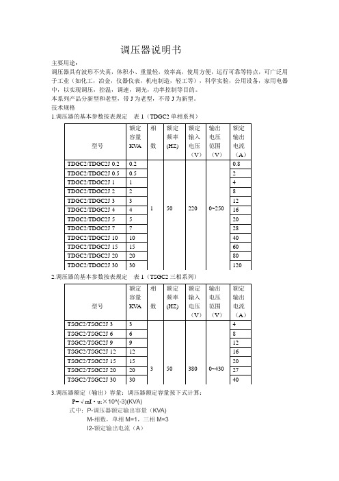
调压器说明书主要用途:调压器具有波形不失真,体积小、重量轻,效率高,使用方便,运行可靠等特点,可广泛用于工业(如化工,冶金,仪器仪表,机电制造,轻工等),科学实验,公用设备,家用电器中,以实现调压,控温,调速,调光,功率控制等目的。
本系列产品分新型和老型,带J为老型,不带J为新型。
技术规格1.调压器的基本参数按表规定表1(TDGC2单相系列)2.调压器的基本参数按表规定表1(TSGC2三相系列)3.调压器额定(输出)容量:调压器额定容量按下式计算:P=√mI·u2×10^(-3)(KVA)式中:P-调压器额定输出容量(KVA)M-相数,单相M=1,三相M=3I2-额定输出电流(A)U2-最大输出电流(V)(三相为线电压)过载(%)不超过(分钟)20 6040 3060 64、调压器绝缘等级为A级,线圈平均温升限值为60℃5、过负荷能力,调压器允许短时间超过额定输出电流值。
但不能超过表2的规定基本原理与主要结构1.基本原理:调压器电刷借助于手轮主轴和刷架的作用,言线圈的磨光表面滑动,变化电刷接触位置、改变一次和二次线圈匝数比,以达到调压的目的。
2、主要结构:①单位结构:单相0.2KV A~10KV A调压器为调压单元结构,一个上端面具有一定宽度的磨光表面的线圈固定在工程塑料的底座上,接触组的电刷在弹簧压力下与线圈的磨光表面金梅接触,转动手轮带动电刷在线圈磨光表面上滑动进行调压。
单元调压器一般为台式,外面有防护通风罩。
单元调压器绕组联接如图一所示:注:图中U1-输入电压(伏)U2-输出电压(伏)D-电刷②单相组装结构,单相大容量调压器是由几个相同规格的单元组装而成,各单元的电刷接触组装在同一主轴上,线圈输入端并联连接平衡电抗器,以平衡单元间电流分布并抑制环流。
单相大容量调压器绕组联接如图2.图3所示:U1-输入电压U2-输出电压D-电刷DK DK1 DK2是平衡电抗器③三相组装结构:三相调压器由三个相同规格的单元同轴组装而成。
RECOM 电源调压器 R-5xxxA 系列数据手册说明书

FeaturesSwitching Regulator• Non-isolated• Synchronous rectification design • Adjustable output voltage• 2, 3, 4 & 5AMP adjustable positive step down integrated switching regulator • Over load protection• Continuous short circuit protection • Efficiency up to 96%R-5xxxPA_DADescriptionThe R-5xxxA series is a high performance 1.2V to 5.5V, 2Amp to 5Amp, 12-Pin SIP (single in-line package) integrated switching regulator (ISR). The synchronous - rectified design yields excellent efficiencies up to 96%. Short circuit protection reduces the short circuit input current to under 50mA. Autosense function compensates for any losses in long circuit loops.DC/DC Converter2,3,4,5 Amp SIP12Vertical &IEC/EN60950-1 certifiedR-542.5xA 4.5 - 18 2.5 1.6 - 5.5 4 91 89 88 300/6800R-543.3xA 4.5 - 18 3.3 1.6 - 5.5 4 93 92 91 300/6800R-545.0xA 6.5 - 18 5.0 3.0 - 5.5 4 95 94 93 300/6800R-551.2xA 4.4 - 18 1.2 1.0 - 3.0 5 81 80 78 300/6800R-551.8xA 4.5 - 18 1.8 1.1 - 4.5 5 86 85 84 300/6800R-552.5xA 4.5 - 18 2.5 1.6 - 5.5 5 90 89 88 300/6800R-553.3xA 4.5 - 18 3.3 1.6 - 5.5 5 92 91 90 300/6800R-555.0xA 7.0 - 1.8 5.0 3.0 - 5.5 5 94 93 92 300/6800Notes:Note1: Vin-Vout ≥ 1.5V~4.0V depending on Vout if adjust function is used Note2: please refer to basic characteristicsNotes:Note3: x can be …P“= vertical through hole x can be …D“ = bent for horizontal through hole mountingModel NumberingOrdering Examples:R-553.3PA Iout= 5A nom. Vout= 3.3VDC P= vertical through holeR-522.5DA Iout= 2Anom. Vout= 2.5VDC D= bent for horizontal through hole mountingPinning (3)Output Current (A)nom. Output VoltageR-5_ __ xASpecifications (refer to standard application circuit, Ta= 25°C)Specifications (refer to standard application circuit, Ta= 25°C)Specifications (refer to standard application circuit, Ta= 25°C)Trim Tables or Calculation2ADC R-521.2PA/DA R-521.8PA/DA R-522.5PA/DA R-523.3PA/DA R-525.0PA/DA 3ADC R-531.2PA/DA R-531.8PA/DA R-532.5PA/DA R-533.3PA/DA R-535.0PA/DA 4ADC R-541.2PA/DA R-541.8PA/DA R-542.5PA/DA R-543.3PA/DA R-545.0PA/DA 5ADC R-551.2PA/DA R-551.8PA/DA R-552.5PA/DA R-553.3PA/DA R-555.0PA/DAVout nom. 1.2VDC 1.8VDC 2.5VDC 3.3VDC 5.0VDC Vout adj.R1R2R1R2R1R2R1R2R1R21.337kΩ 3.7kΩ750Ω1.511.5kΩ10kΩ2.1KΩ390Ω1.68.2kΩ18kΩ 3.0KΩ750Ω1.7 6.5kΩ41kΩ 4.1KΩ 1.2kΩ1.8 5.2kΩ 5.6KΩ 1.7kΩ1.9 4.3kΩ36kΩ7.5KΩ2.2kΩ2.03.6kΩ 1.8kΩ10.5KΩ 2.8kΩ2.4 2.1kΩ 5.2kΩ82KΩ 6.8kΩ2.5 1.8kΩ 4.3kΩ8.5kΩ2.6 1.65kΩ3.6kΩ33kΩ10.5kΩ3.0 1.05kΩ 2.1kΩ 6.2kΩ33kΩ470Ω3.2 1.65kΩ4.1kΩ110kΩ 1.6kΩ3.3 1.5kΩ 3.4kΩ 2.2kΩ3.4 1.35kΩ 2.9kΩ36kΩ 3.0kΩ3.6 1.07kΩ 2.2kΩ11kΩ4.7kΩ3.9780Ω 1.4kΩ4.7kΩ8.5kΩ4.5390Ω650Ω 1.6Ω30kΩ4.9350Ω820Ω220kΩ5.0290Ω680Ω5.1220Ω560Ω28kΩ5.539Ω190Ω 2.6kΩSpecifications (refer to standard application circuit, Ta= 25°C)PROTECTIONSParameter Condition Value Short Circuit Protection (SCP)continuous, automatic recovery Short Circuit Input Current50mA max.continued on next pageSpecifications (refer to standard application circuit, Ta= 25°C)DIMENSION AND PHYSICAL CHARACTERISTICSParameterTypeValueMaterial case pottingnon-conducive black plastic, (UL94 V-0)epoxy, (UL94 V-0)Dimension (LxWxH)32.2 x 9.1 x 15.0mmWeight9g typ.continued on next pageENVIRONMENTALParameterConditionValueOperating Temperature Range *************************************/s-40°C to +85°CMaximum Case Temperature +110°C Thermal Impedance @ natural convection 0.1m/s25°C/W Operating Humidity non-condensing95% RH max.Operating Altitude 2000m Pollution Degree PD2MTBFaccording to MIL-HDBK 217F, G.B.+25°C +85°C749 x 103 hours 150 x 103 hoursSAFETY AND CERTIFICATIONSCertificate Type (Safety)Report / File NumberStandard Information Technology Equipment, General Requirements for Safety 1605077-12IEC60950-1:2005, 2nd Edition + AM2:2013EN60950-1:2006 + AM2:2013EAC RU-AT.49.09571TP TC 004/2011RoHS 2+RoHS-2011/65/EU + AM-2015/863Specifications (refer to standard application circuit, Ta= 25°C)PACKAGING INFORMATIONParameter Type ValuePackaging Dimensions (LxWxH)R-5xxxDAR-5xxxPA520.0 x 20.0 x 19.0mm530.0 x 23.0 x 19.0mmPackaging Quantity tube 15pcs Storage Temperature Range-40°C to +125°CThe product information and specifications may be subject to changes even without prior written notice.The product has been designed for various applications; its suitability lies in the responsibility of each customer. The products are not authorized for use in safety-critical applications without RECOM’s explicit written consent. A safety-critical application is an application where a failure may reasonably be expected to endanger or cause loss of life, inflict bodily harm or damage property. The applicant shall indemnify and hold harmless RECOM, its affiliated companies and its representatives against any damage claims in connection with the unauthorizeduse of RECOM products in such safety-critical applications.。
基尔尔电气自动电压调节器AVC63-12和AVC125-10说明书
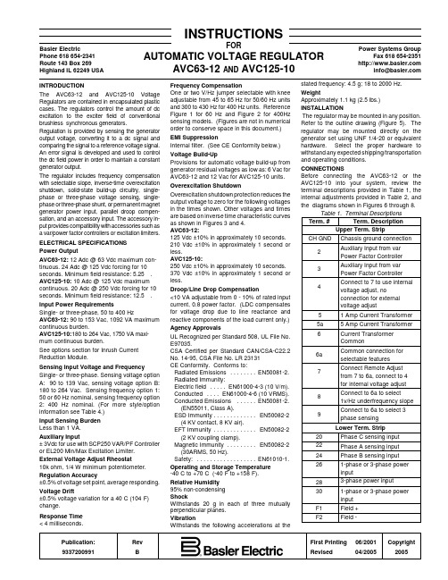
Publication:Rev First Printing 06/2001Copyright 9337200991BRevised04/20052005Basler ElectricPhone 618 654-2341Route 143 Box 269Highland IL 62249 USAPower Systems GroupFax 618 654-2351***************INSTRUCTIONSFORAUTOMATIC VOLTAGE REGULATORAVC63-12 AND AVC125-10INTRODUCTIONThe AVC63-12 and AVC125-10 Voltage Regulators are contained in encapsulated plastic cases. The regulators control the amount of dc excitation to the exciter field of conventional brushless synchronous generators.Regulation is provided by sensing the generator output voltage, converting it to a dc signal and comparing the signal to a reference voltage signal.An error signal is developed and used to control the dc field power in order to maintain a constant generator output.The regulator includes frequency compensation with selectable slope, inverse-time overexcitation shutdown, solid-state build-up circuitry, single-phase or three-phase voltage sensing, single-phase or three-phase shunt, or permanent magnet generator power input, parallel droop compen-sation, and an accessory input. The accessory in-put provides compatibility with accessories such as a var/power factor controllers or excitation limiters.ELECTRICAL SPECIFICATIONS Power OutputAVC63-12: 12 Adc @ 63 Vdc maximum con-tinuous. 24 Adc @ 125 Vdc forcing for 10seconds. Minimum field resistance: 5.25 S .AVC125-10: 10 Adc @ 125 Vdc maximum continuous. 20 Adc @ 250 Vdc forcing for 10seconds. Minimum field resistance: 12.5 S .Input Power RequirementsSingle- or three-phase, 50 to 400 HzAVC63-12: 90 to 153 Vac, 1092 VA maximum continuous burden.AVC125-10: 180 to 264 Vac, 1750 VA maxi-mum continuous burden.See options section for Inrush Current Reduction Module.Sensing Input Voltage and FrequencySingle- or three-phase. Sensing voltage option A: 90 to 139 Vac, sensing voltage option B:180 to 264 Vac. Sensing frequency option 1:50 or 60 Hz nominal, sensing frequency option 2: 400 Hz nominal. (For more style/option information see Table 4.)Input Sensing Burden Less than 1 VA.Auxiliary Input± 3Vdc for use with SCP250 VAR/PF Controller or EL200 Min/Max Excitation Limiter.External Voltage Adjust Rheostat10k ohm, 1/4 W minimum potentiometer.Regulation Accuracy±0.5% of voltage set point, average responding.Voltage Drift±0.5% voltage variation for a 40/C (104/F)change.Response Time < 4 milliseconds.Frequency CompensationOne or two V/Hz jumper selectable with knee adjustable from 45 to 65 Hz for 50/60 Hz units and 300 to 430 Hz for 400 Hz units. Reference Figure 1 for 60 Hz and Figure 2 for 400Hz sensing models. (Figures are not in numerical order to conserve space in this document.)EMI SuppressionInternal filter. (See CE Conformity below.)Voltage Build-UpProvisions for automatic voltage build-up from generator residual voltages as low as: 6 Vac for AVC63-12 and 12 Vac for AVC125-10 units.Overexcitation ShutdownOverexcitation shutdown protection reduces the output voltage to zero for the following voltages in the times shown. Other voltages and times are based on inverse time characteristic curves as shown in Figures 3 and 4.AVC63-12:125 Vdc ±10% in approximately 10 seconds.210 Vdc ±10% in approximately 1 second or less.AVC125-10:250 Vdc ±10% in approximately 10 seconds.370 Vdc ±10% in approximately 1 second or less.Droop/Line Drop Compensation<10 VA adjustable from 0 - 10% of rated input current, 0.8 power factor. (LDC compensates for voltage drop due to line reactance and reactive components of the load current only.)Agency ApprovalsUL Recognized per Standard 508, UL File No.E97035.CSA Certified per Standard CAN/CSA-C22.2No. 14-95, CSA File No. LR 23131CE Conformity. Conforms to:Radiated Emissions ........EN50081-2.Radiated Immunity:Electric field .....EN61000-4-3 (10 V/m).Conducted ....EN61000-4-6 (10 VRMS).Conducted Emissions ......EN50081-2.(EN55011, Class A).ESD Immunity .............EN50082-2(4 KV contact, 8 KV air).EFT Immunity .............EN50082-2(2 KV coupling clamp).Magnetic Immunity .........EN50082-2(30ARMS, 50 Hz).Safety:..................EN61010-1.Operating and Storage Temperature -40/C to +70/C (-40/F to +158/F).Relative Humidity 95% non-condensing ShockWithstands 20 g in each of three mutually perpendicular planes.VibrationWithstands the following accelerations at thestated frequency: 4.5 g; 18 to 2000 Hz.WeightApproximately 1.1 kg (2.5 lbs.) INSTALLATIONThe regulator may be mounted in any position.Refer to the outline drawing (Figure 5). The regulator may be mounted directly on the generator set using UNF 1/4-20 or equivalent hardware. Select the proper hardware to withstand any expected shipping/transportation and operating conditions.CONNECTIONSBefore connecting the AVC63-12 or the AVC125-10 into your system, review the terminal descriptions provided in Table 1, the internal adjustments provided in Table 2, and the diagrams shown in Figures 6 through 8.Table 1. Terminal Descriptions Term. #Term. DescriptionUpper Term. Strip CH GNDChassis ground connection 2Auxiliary Input from var Power Factor Controller 3Auxiliary Input from var Power Factor Controller 4Connect to 7 to use internal voltage adjust, noconnection for external voltage adjust5 1 Amp Current Transformer 5a 5 Amp Current Transformer 6Current Transformer Common6a Common connection for selectable features 7Connect Remote Adjust from 7 to 6a, connect to 4for internal voltage adjust 8Connect to 6a to select1v/Hz underfrequency slope 9Connect to 6a to select 3phase sensing Lower Term. Strip20Phase C sensing input 22Phase A sensing input 24Phase B sensing input 261-phase or 3-phase power input283-phase power input 301-phase or 3-phase power input F1Field +F2Field -CAUTIONDo not flash the field with the generator in motion. Regulator damage may result.CAUTIONThe factory calibration (FAC CAL)adjustment is intended for use by factory technicians only. The following procedure can be used if the factory calibration has been disturbed.Table 2. Internal AdjustmentsAdjust. Adjustment.Description DRP Voltage Droop Adjust FAC CAL FAC CAL is a factory voltageadjust range calibration. No customer adjustment is required.VLT ADJ Multi-Turn Voltage Adjust UF Underfrequency Knee Adjust STB Stability Adjust OPERATION GeneralTable 3 provides system start-up procedures for the AVC63-12 and AVC125-10 Voltage Reg-ulators. Symptoms of problems occurring during start-up that arise from incorrect regulator adjustment and certain generator system problems that resemble faulty regulation are included together with possible solutions. Simplifying the system by eliminating components, such as remote adjust poten-tiometers and other non-essential items can be helpful in the troubleshooting process. Ad-justments, options, and an operational test are included in the paragraphs after the table.Preliminary Set-UpTo prevent damage to the regulator, ensure that the regulator has been installed and connected in accordance with the paragraphs in Instal-lation and Connections before proceeding with the system start-up. System Start-UpRefer to Table 3 for system start-up.ADJUSTMENTS Field FlashingWhen the regulator is operated with the generator for the first time, the polarity of the residual magnetism may not be correct or of sufficient magnitude. If generator residual voltage is less than 6 Vac for the AVC63-12 or 12 Vac for the AVC125-10 at terminals 26,28and/or 30 shut down the prime mover and proceed with the following steps:1.With the prime mover at rest, apply a dcsource (ungrounded), of not more than 24Vdc, to terminals F1 (positive) and F2(negative) in series with a limiting e one (1) ohm of resistance for each volt from the dc power source with a power rating of least one (1) watt per ohm.EXAMPLE: If using a 24 Vdc source, use a 24-ohm, 24-watt resistor.2.Allow the field to be flashed for approx-imately ten seconds before removing the dc source.3.If voltage build-up does not occur afterperforming steps (1) and (2), verify the polarity of the dc source used in steps (1)and (2) and re-perform.Frequency Roll-Off (UF Knee) Adjustment The underfrequency knee (roll-off) is typically set below the nominal system frequencies.When the generators speed falls below the knee set point of the regulator, generatorvoltage is reduce proportional to the speed of the machine. To adjust the underfrequency knee, follow the steps below:(1)Adjust the generator frequency for nominal frequency (50, 60, or 400 Hz).(2)Adjust the underfrequency potentiometer (UF) CCW.(3)Adjust the Voltage Adjust potentiometer for nominal generator voltage.(4)Adjust the underfrequency potentiometer (UF) CW until the voltage begins to decrease.(5)Adjust the underfrequency potentiometer (UF) CCW until the voltage just returns to the value set in Step 3.(6)The underfrequency knee is now set just below the nominal operating frequency. Further rotation in the CCW direction will lower the knee frequency set point at which underfrequency compensation begins.(7)Connecting a jumper from terminal 8 to terminal 6a will provide an underfrequency slope of 1 P.U. V/Hz. No connection to terminal 8 will result in an underfrequency slope of 2 P.U. V/Hz. The slope can also be selected on the 400Hz models. However, the actual V/Hz curve is approximately 1 P.U. or 2 P.U.depending if the terminal 8 is jumpered to 6a or not.Stability (STB) AdjustmentAn oscilloscope or other voltage-recording device should be used if an optimal stability setting is desired. Adjust the stability setting with the generator at no load. Good response can be obtained with the following procedure.(1)Rotation of the front panel STB control in the clockwise (CW) direction will slow response time.(2)Rotation of the front panel STB control in the counter-clockwise (CCW) direction will speed response time. If rotated too far CCW,the generator voltage may oscillate (hunt).(3)Rotate the front panel STB control CCW until the system just begins to oscillate and then rotate CW just past the point where oscillation occurred. Apply various amounts of loads to determine proper stability performance.Voltage (VLT ADJ) Adjustment(1)Installation of a jumper across terminals 4and 7 allows the internal (front panel) VLT ADJ adjustment to vary the generator nominal voltage over the operating range.(2)Remove the jumper between terminals 4and 7 and connect a 10k ohm external voltage adjust potentiometer across terminals 6a and 7to allow operation of the external voltage adjust potentiometer. The internal voltage adjustment should be set fully CW for proper operation of the external adjustment. It should be noted, as the external potentiometer resistance in-creases, generator voltage also increases.Factory Calibration (FAC CAL) Adjustment(1)With the voltage regulator operating on a generator, adjust the calibration potentiometerfully CCW and the external voltage adjust potentiometer fully CW. Adjust the FAC CAL potentiometer CW until the generator voltage reaches the desired maximum voltage setting.The unit is calibrated and the calibration potentiometer can be sealed. Parallel Droop CompensationVariable parallel droop compensation levels can be obtained by adjusting the droop poten-tiometer. CW rotation increases the amount of droop for a given condition.Line Drop CompensationWhen the sensing input CT connections are swapped to provide LDC, the droop adjustment becomes the LDC adjustment.OPTIONSThe AVC63-12 and AVC125-10 may be equipped with the following options to enhance operational characteristics. Characteristics of these options are defined in the following para-graphs.Remote Voltage AdjustConnect a 10 k ohm, 2 watt potentiometer from terminals 6a to 7, remove the jumper from terminal 4 to 7 and adjust the internal voltage adjust potentiometer fully CW to allow operation of a remote voltage adjust.Inrush Current Reduction ModuleAn ICRM-15 (Inrush Current Reduction Module) is required when energizing the AVC63-12 and AVC125-10 from a source that is already at the regulators input power ratings.This module minimizes the amount of inrush current that could be seen when power is applied.Excitation DisableThis option provides for disabling of the excitation system by removal of power from the voltage regulator. A switch removing voltage from terminals 26, 28 and/or 30 will remove power.Excitation LimiterThis EL200 option provides an initial fast acting limit of the field current at a pre-selected level.Once the field current has changed to the selected level, the output provides a signal to the regulator to change the excitation.Var/PF ControlThis option allows the AVC63-12 and the AVC125-10 to regulate the var and power factor while the generator is connected to an infinite or utility bus. The var/PF option (Model Number SCP250G-50 for 50-hertz operation or SCP250G-60 for 60-hertz operation) supplies a dc signal into the AVC63-12 and AVC125-10terminals 2 and 3 to regulate the SCP250 var or power factor setting. (See Figure 7 for inter-connection diagram.)Current Boost SystemWith this CBS212 option, if the generator output voltage drops below the preset operation point due to a short or large motor starting, the current boost function detects the voltage drop.The function then provides full current boost to the generator exciter until the voltage returns to a level just above the operation point.Manual Voltage ControlThis option provides a manual back-upchannel for manually controlling the generator output during generator start-up and commissioning orin the unlikely event that the voltage regulator should fail. Manual voltage controller model MVC-112 is suitable for use with either the AVC63-12 or the AVC125-10 voltage regulator.Table 3. System Start-Up1.Perform the preliminary set-up.2.Start prime mover and bring up to rated speed.If the voltage does not build up:a.Flash Fieldb.Remove power for 1 minute toallow the overexcitation circuit to reset.3.Slowly adjust VOLT adjustment or external voltage adjust rheostat until voltage reaches nominal.If the voltage does not build up to therated value, check the generator output for a shorted or excessive load.4.Apply and remove load to check stability.If the generator response is too slow or is hunting (oscillating):a.Check generator output for shortedor excessive load. Adjust STB with no load applied.b.Check stability of governor system.5.Check regulation under normal operating conditions.If the regulation is poor:a.Check that the prime mover is upto rated speed.b.Check that the voltmeter isconnected at the same point as the regulator sensing.e an average sensing voltmeter(not an RMS sensing voltmeter).Table 3. System Start-Up (Continued)6.Reduce generator frequency. Generator output should decrease from this point.If the generator output voltage does not decrease at desired frequency:a.Check that all the wiring is inaccordance with the connection diagrams provided in these instructions.b.Adjust FREQ control.OPERATIONAL TESTThis test is designed to test all eight models of the AVC63-12 and AVC125-10. See Table 4for appropriate testing voltages and frequencies.To operationally test any AVC63-12 or AVC125-10, perform the following steps.a.Connect the voltage regulator as shown by Figure 9 and apply appropriate voltages.b.Adjust the front panel VLT ADJ control fully counterclockwise (CCW).RESULT: Observe that the lamp is OFF.c.Adjust the front panel VLT ADJ control clockwise (CW).RESULT : Observe that the lamp is now ON.d.Adjust the front panel VLT ADJ control until the lamp just goes out.Regulator operation is satisfactory if the above results are obtained. Stability, however, must be tested with the generator and regulator in operation.MAINTENANCEPreventive MaintenanceA periodic inspection should be made of the voltage regulator to ensure that it is clean and free from accumulations of dust and moisture. Be sure that all connections are clean and tight.TroubleshootingIn case of failure/defective operation of the unit, simplifying the system by eliminating com-ponents, such as remote adjustpotentiometers and other non-essential items can be helpful in the troubleshooting process.Table 4. Testing ParametersInput SensingModel Power Vac Freq.AVC63-12A1120120 50/60AVC63-12A2120120400AVC63-12B112024050/60AVC63-12B2120240400AVC125-10A1 24012050/60AVC125-10A2240120400AVC125-10B124024050/60AVC125-10B2240240400Figure 1. 60 Hertz Frequency CompensationFigure 2. 400 Hertz Frequency CompensationL C23Part of AVC63-12or AVC125-10Part of EL200P0009-25.vsd 06-26-01A CPart of SCP250NOTE: AVC Units may be connected to either the EL200 or the SCP250 using the terminals as shown in place of this series interconnection. See the unit Instruction Manuals for more information.Figure 7. AVC Interconnection DiagramFigure 9. Operational Test Set-Up。
调压装置培训
定警戒值时,切断阀自动介入将该通道关闭,避免下游系统压力异常而危及用户安全。
(5)放散阀:也是一个安全装置。其设置目的是防止紧急切断阀因非故障因素而关闭。当调压器出口
1
管道因非故障因素而压力暂时升高达到一定警戒值时,放散阀自动开启给管道卸压,压力降低至低于开启
警戒值后阀自动关闭。
较复杂的调压站除具有上述功能组件外还可包含下列各组件中的部分或全部:
较轻
较重
最轻
价格
贵
较廉
较廉
最廉
备件费用
最廉
较贵
较廉
最贵
本公司销售的调压器可按不同的原则分类如下:
3
燃气调压器
直接作用式 间接作用式
NORVAR
DIVAL
轴流式 Zetaflux
截至式
REVAL182 REFLUX819
本公司经销的调压器的型号及其参数汇总于表 1 中。 表 2 燃气调压器的性能
型号 NORVAL
DIVAL STAFLUX185
进口压力范 规格
围(MPa) DN25~80
1″~8″ 0.0.1~1.6
DN100~200 0.01~0.8
1″ 1″2″
50、100 0.01~0.5 160、250(带
切断阀) 0.01~1.6 160、250(不 带切断阀) 0.01~1.9
1~3″
~10
出口压力范围 最小压 精度 关闭压 (kPa) 降(kPa) 等级 力等级
(6)绝缘接头:作用为防止调压站内高速燃气的流动摩擦所产生的杂散电流流入地下管网而破坏其阴
极保护效果,以及降低杂散电流的干扰腐蚀。
(7)流量计:计量燃气流量。分两种,一种供计费用,一种供监察用
Norgren B07滤芯与调压器说明书

A....PTFB....ISO Rc taper G....ISO G parallel 1....1/8"2....1/4"A....0,1 to 0,7 bar (1 to 10 psig)E....0,3 to 3,5 bar (5 to 50 psig)K....0,3 to 7 bar (5 to 100 psig)A....Automatic M...Manual1....5 µm 3....40 µm Transparent..Relieving .........Without............01Transparent..Relieving .........With.................02Transparent..Non-relieving...Without............03Transparent..Non-relieving...With.. (23)B07Installation & MaintenanceInstructions CAUTIONWater vapor will pass through these units and couldcondense into liquid form downstream as air temperaturedrops. Install an air dryer if water condensation could havea detrimental effect on the application.WARNINGThese products are intended for use in industrialcompressed air systems only. Do not use these productswhere pressures and temperatures can exceed those listedunder Technical Data.Polycarbonate plastic bowls can be damaged andpossibly burst if exposed to such substances as certainsolvents, strong alkalies, compressor oils containing ester-based additives or synthetic oils. Fumes of thesesubstances in contact with the polycarbonate bowl,externally or internally, can also result in damage. Cleanwith warm water only.Use metal bowl in applications where a plastic bowlmight be exposed to substances that are incompatible withpolycarbonate.If outlet pressure in excess of the filter/regulatorpressure setting could cause downstream equipment torupture or malfunction, install a pressure relief devicedownstream of the filter/regulator. The relief pressure andflow capacity of the relief device must satisfy systemrequirements.The accuracy of the indication of pressure gauges canchange, both during shipment (despite care in packaging)and during the service life. If a pressure gauge is to beused with these products and if inaccurate indications maybe hazardous to personnel or property, the gauge should becalibrated before initial installation and at regular intervalsduring use.Before using these products with fluids other than air,for non industrial applications, or for life-support systemsconsult Norgren.。
龙力电器 三相预置数字调压器 TNSGC 系列 说明书
TNSGC系列三相预置数字调压器使用说明书中山市龙力电器有限公司……………………………………………..前 言……………………………………………….首先,感谢您选择我公司调压器系列产品!本手册提供给使用者安装、使用、维护本产品的相关注意事项,为了确保能够正确地安装和操作本产品,请在安装使用前详细阅读本手册,若有任何疑问之处请联络我公司或代理商洽询,我们的专业人员真诚为您服务。
....................................目 录....................................z产品介绍 (1)z技术参数 (2)z电气原理图 (3)z环境要求 (4)z各部分名称 (5)z安装接线 (6)z操作使用 (8)z注意事项 (18)z日常维护工作 (19)z异常情况处理 (20)z订货须知 (21)1.产品介绍1-1.概 述TNSGC系列三相预置数字自动调压器(以下简称调压器)它采用基于微处理器的数字控制技术,对设备的输出电压进行调整和优化处理。
调压器的输出电压能够任意设置一个固定点,由按键控制电压的变化。
预先设置一个电压(可在调整范围内任意设置一个固定点),由一个电位器调整到所需电压点,可通过外置电压表观察设定电压值。
电压值设定后,调压器会自动调节至所设定电压。
产品广泛适用于各类工厂及科研单位等所有需要进行产品老化试验的场所。
1-2. 产品特点(1)容量大、效率高、无波形畸变。
(2)电压调节平稳,控制功能强。
(3)瞬间超载能力大,可长期可靠连续工作。
(4)采用LED数字显示,清晰、准确、分辨率高,实时显示电压、电流、功率等因素,可让您清楚地了解稳压器的运行状态。
(5)薄膜按键操作,安全可靠。
(6)保护功能齐全,设有过载、过压、欠压、缺相、短路等故障自动保护和报警功能,确保设备及负载的安全运行。
(7)两组输出切换,每组可根据你的需要分时段在可设置范围内调整输出电压,及多种运行模式选择,充分满足你的要求。
N型调压器说明书
用户在订货时须提供以下参数: a.气体的种类; b.气体进口压力范围(最大值、正常值、最小值); c.气体出口压力范围(最大值、正常值、最小值); d.气体的最大流量和最小流量; e.可选功能中的特殊要求; f.用户的其它要求。
成都华泰燃气设备有限公司 电话:(028)82006028
传真:(028)87485089
L
型号
法兰
L1 D
H1 H
RTJ-43/25N DN25 197 380 280 280 380
RTJ-43/50N DN50 254 400 325 350 420
RTJ-43/80N DN80 318 580 480 410 500
RTJ-43/100N DN100 352 580 480 430 540
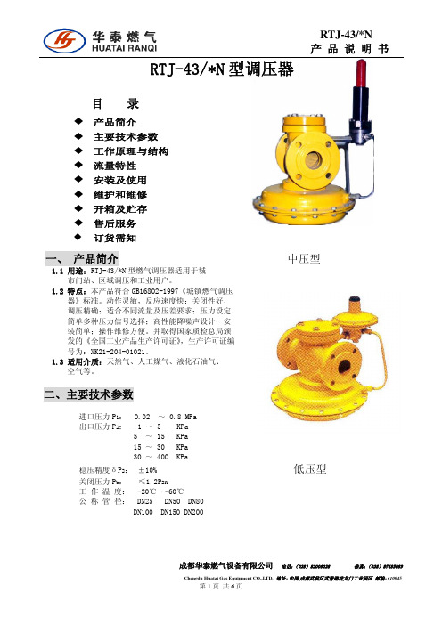
RTJ-43/*N 产品说明书
RTJ-43/*N 型调压器
目录
产品简介 主要技术参数 工作原理与结构 流量特性 安装及使用 维护和维修 开箱及贮存 售后服务 订货需知
一、 产品简介
1.1 用途:RTJ-43/*N 型燃气调压器适用于城 市门站、区域调压和工业用户。
单位 KPa
MPa
RTJ-43/25N 210 385 370 350 430 410 400 380 630 600 570 540 790 760 730 700 880 860 840 800 1060 1000 960 900 1390 1300 1200
RTJ-43/50N 460 720 700 650 820 800 760 720 1380 1300 1250 1200 1690 1610 1580 1500 1870 1800 1720 1650 1390 1300 2220 2100 2900 2820 2760
Honeywell变压器产品参数手册说明书

PA/V A SOLUTIONSVARIODYN D1Digital Public Address andVoice Alarm System2 | Voice Alarm is increasingly important in the safe management of buildings. A voice message informs occupants exactly what to do in an emergency and it is a long established fact that people respond more quickly and are more likely to take the correct action during an evacuation if voice messages are used instead of tone sounders.THE ROLE OF VOICE ALARM• Clear directions to people in the building• Live messages giving exactinstructions to people whoare not familiar with the surroundings • Customised pre-recordedmessages (available inmultiple languages)• Up to 20 minutes shorter response time to fire alarm• Serial Interface toHoneywell fire panels for EVAC guidance and time-controlled evacuation • High-end non-emergency features such asequalizing, automatic volume control and multi-channel announcements as well as backgroundmusic • Alarm cancellation and manual evacuation override controlBENEFITS | 3PUBLIC ADDRESS -MORE THAN VOICE ALARMVoice Alarm systems are more frequently used as public address and entertainment systems than only as automatic evacuation system inpublic buildings with a high number of visitors.• Paging and evacuation with zone-dependent messages • Integration with airport/train station managementsystems• Multiple channel/zone music broadcasting • Sport/concert hall and stadium sound systemintegration • Time-scheduled announcements• Touch screen operation panels• Operation from intuitive computer management systems • High quality background music for high class shopping experienceFEATURES PUBLIC ADDRESS PROVIDES ADDITIONALL Y:4 |Selecting, designing and commissioning a PA/VA system can be challenging. At Honeywell we have a team of experts that will help you build the most suitable system for your building.The first step is to decide exactly what type of PA/VA system you will need. This will largely depend on the size and functional complexity of your building.The following two types of systems are available that start from small ‘Compact Solution’ packages suitable for single storey buildings such as shops and offices and move up to a custommade ‘Modular System’ that will consist of a number of distributed systems linked together for large structures such as exhibition fairgrounds and airports.VOICE ALARMCOMPETENCE FOR YOU• Controlling and indicating equipment certified to EN 54-16 and EN 54-4• Complete range of EN 54-24 certified loudspeakers • Flexible systems that supports both simple and the most complex communication needs • High quality digital audio matrix• Intuitive touchscreen Graphical User Interface that manages the entire system • Phased evacuation scenarios • Situation, location & evacuation phasedependent voice messages • Exact guidance regarding evacuation routes• Freely configurableevacuation scenarios with logical dependencies • Dedicated Honeywelldesign and project supportSYSTEMS KEY FEATURES |5 LEISURE COMPLEXES SCHOOLS SMALL HOTELS OFFICESTHE COMPACT SOLUTION:COMPRIO D1An easy-to-install PA/VA system.Suitable for small to medium buildingswith up to 24 loudspeaker zones.APPLICATIONS• Leisure complexes• Supermarkets• Schools• Hotels• OfficesBENEFITS• Amplifier with build-in PSU available• ‘Off the Shelf’ Package• Installation within two hours• Only 8 HU rack space incl. amplifier,charger and batteries• Ensured compliance to ENstandards• Complete solution for up to 24zones• max. 2000 W output powerexpandable with additional DOM/AMPs6 | Our PA/VA systems can be distributed and networked together to deliver the most comprehensive and powerful solution for a wide range of applications. Suitable for mid to large and complex sites.THE MODULAR SOLUTION V ARIODYN D1• Industrial facilities • Universities• Airports and transport hubs • Stadiums• Exhibition halls and fairgrounds • Mega Shopping Malls • Large Office buildingsAPPLICATIONS• Scalable and modular to adapt to constant changes and demands• Supports a large number of evacuation and/or paging zones • Manages complicated evacuation strategies in the event of an emergency • IP connectivity tolink multiple nodes (VARIODYN D1 DOM)BENEFITS• Up to 120 announcements at the same time• Pre-recording and playbackof messages• Secured data link to various Honeywell Fire Alarm Systems• Decentralized and redundant system architecture• Interface to BuildingManagement Systems (e.g. Honeywell EBI)• Redundant network and Call Stations linksComputer Management Station (PAMMI)Decentralized | 7STADIUMS AIRPORTS SHOPPING MALLS RAILWAY STATIONSCUSTOMISED CONTROLThe PAMMI (Public Announcement Man Machine Interface) software provides monitoring and control of the Honeywell Voice Alarm System via a graphical user interface on a Microsoft Windows® based personal computer.PERFECT SYMBIOSIS VOICE ALARM AND FIRE ALARMAREA BY AREA, TARGETED AND ORDERL Y:EVACUATION PROCEDURE EXAMPLE AT THE AIRPORT• There is a short-circuit in the baggage sortingarea on the 1st sub-level,section B of the airport. • The fire detector detects the formation of smokeand transmits theinformation to the firealarm control panel.• The fire alarm system simultaneously initiatesalarms to the securityservices and the voicealarm system.• The security inspectorassesses the situation viathe video camera installedon-site and then activatesa stored a nnouncementto the personnel with thepush of a button.• Due to the increasingformation of smoke,the fire alarm systemautomatically closes thefire door in the affectedarea.Synergies arise through digital coupling of the fire alarm system with the voice alarm system, thus facilitating an orderly, area-specific evacuation during emergencies: If a fire is detected by the connected fire detectors and then received by the fire alarm control panel, this automatically activates the voice alarm system. The endangered areas are then selected automatically and informed via the PA/VA system, while at the same time the fire alarm control panel activates fire protection systems, for example, fire doors, air-conditioning and ventilating systems, elevator controls or smoke dampers.The combination of voice alarm and fire alarm technology not only offers functional advantages, there are economical advantages as well: PA/VA reduces the total EVAC time significantly, a PA/VA system is not much more expensive than standard sounders, while it adds valuable support by increasing productivity of building occupants.8 | | 9VARIODYN D1 AND COMPRIO PA/VA SYSTEM DIAGRAM Thanks to its modular construction and the varioussystem components, the VARIODYN D1 system can easily DCS Digital Call Station DSCF DSC for Firefighter Fire Alarm Control PanelInterfaceDOMAMP PSUDCSF 1/12Configuration via LaptopCD playerETCSDCS PlusCentral Operating Terminal(PAMMI, WINMAG, Honeywell EBI etc)Loop Isolator ModuleAdvanced,Automatic Volume Control10 | WINMAGPLUSONE MANAGEMENT SYSTEM FOR ALLPERFORMANCE FEATURES OF THE VARIODYN D1 INTERFACE WINMAGPLUS DRIVER• System configuration readout of a VARIODYN D1 network to take it over via import files to WINMAGplus application.• Fault and status indication of the VARIODYN D1 system components: • DOM, SCU, DAL bus devices like DCS and • UIM, Amplifiers (each channel)• Audio and control contact inputs and outputsThe WINMAGplus hazard management system lets you create a scalable software solution with superb levels of integration with different sub-systems.In case of Voice Alarm system, VARIODYN D1 is connected via Ethernet/RJ45 to the same network as the WINMAGplus server. This enables the VARIODYN D1 integration with systems such as: fire alarm, fire extinguishing, smoke and heat control, escape routes, CCTV, access control, intrusion detection, emergency lighting as well as BMS and others via open protocols.• Call station function: • Microphone switched to pre-selectable or fixed targets for live-spoken announcements• Playback of pre-recorded announcements onselectable or fixed targets• Display, update and controlof: • Volume• Volume presettings (min., max., alarm)• Audio signal levels • Control contacts | 11Client Ma chinesHazardManagementVideo SystemsIntrusion Detection SystemsAccess ControlPublic Address & Voice AlarmFire AlarmFireExtinguishingFireControlsEmergency LightingBuildingManagement Systems12 | CHALLENGING PROJECTS REQUIRE BEST DESIGN AND EXPERTISEBY CEN/TS 54-32 EUROPEAN STANDARD VA SYSTEM CAN BE DESIGNED IN 2 WAYS TO ACHIEVE REQUIRED INTELLIGIBILITY: 1. Simplified, prescriptive method, requiring loudspeakers mounted every 6 meters or less.2. Detailed method, requiring in practice acoustics simulations as VA system design base regarding spacing, location, type selection, audio equalizing and proper orientation of loudspeakers.Acoustic simulations are paramount for a proper PA/VA system design in complex, tough and large areas. EN 50489 and CEN/TS 54-32 require minimum intelligibility level from installed VA systems. Installing and planning VA systems bears a risk of failure during intelligibily measurements in the handover phase. Toprevent such critical situations and underbudgeting of VA systems acoustic simulations are the only guarantee. |13EXAMPLE OF THE ACOUSTIC SIMULATION OF AN AUDITORIUM Acoustic simulation software provides to precisely and reliably assess sound pressure level (dB) and intelligibility level (STI/CIS). The software calculates the simulatedroom as a space map in 3D, enabling the user to verify the selected type, location and setting of loudspeakers.Voice Alarm system design for acoustically challenging areas must be based on professional, quality simulations,prepared by experienced acoustic experts.Our Technical Support Team provides expertise, experience, tools and wide portfolio of certified VA loudspeakers to assure our partners and system designers that Variodyn D1 system designs will pass acceptance tests.14 | VARIODYN D1 PRODUCT FAMIL YAll of the components of the VARIODYN D1 product family are compatible, interchangeable and optimally adapted to the customers growing needs. As varied as the requirements may be, all of the components are modular designed andcan be combined with each other quick and easy.ComprioComprio is a voice alarm system optimised for small and medium-size facilities such as schools,hotels, leisure centres and offices. It's characterised by its compact design, wide performance range and its flexibility.Digital Output Module (DOM)The Digital Output Module (DOM) is the heart of the Honeywell Voice Alarm and Public Address system. Managing either 8 or 24 zones the DOM routes up to 4 channels of audio from amplifiers to any individual zone or group of zones.Class D Power AmplifiersCombining the latest in digitalaudio technology with the integrity necessary for emergency Voice Alarm systems to satisfy the requirements of EN54 part 16.Direct Drive Power Amplifier4-channel Direct Drive Amplifier 4 x 300 W or 4 x 500 W power outputs or unit providing 4 x 125 W or 4 x 250 W power outputs with integral EN 54-4 certified battery charger.Paging Microphone DCSPlus The paging microphone allows for the selection of loudspeakerzones, and the transmission of voice announcements via programmable buttons.Ethernet Touch Call Station (ETCS)This EN 54-16 certified touch screen call station provides a user friendly, multilingual and multi-user interface support with high failure safety due to redundant transmission routes via Ethernet (PoE possible). It includes audio memory up to 27 hour and a USB stick can be connected to play audio files as well.Universal Interface Module (UIM)Interface module enables audio or control connection to third party systems such as CD players, security systems and other PA/VA or building management control systems.System Communication Unit (SCU)The System Communication Unit (SCU) is an integrated digital audio memory source able to simultaneously record and play back multiple audio data streams.PAMMI PublicAnnouncement User Interface The PAMMI software provides connection and control of the Honeywell Voice Alarm System via a graphical user interface on a Microsoft Windows ® based PC.Emergency Microphones Emergency Microphone used to select and broadcast pre-programmed alarm messages and live voice announcements during emergency situations by security operator or fire brigade commander. | 15LOUDSPEAKERSHoneywell offers loudspeakers, specially designed to meet various requirements and specifications in many project types e.g.Excellent acoustic performance to realize clear, understandable voice announcements or high quality background music.• Cost-effective types• Well designed, modern appearance• Easy for installation to reduce time, efforts and costs • Robust material to offer long lifetime•Models with ceramic terminal block and thermofuseCeiling Loudspeaker• Metal or plastic ceilingloudspeakers• Several power tappings withsimple setting• Partly dual-cone speaker toensure best audio performance • Appropriate for indoorapplications such as offices, warehouses, schools etcHorn Speaker• Clear voice messagereproduction for open and outside areas• Offers a high sound pressureand long-lasting weather resistanceSound Projector• Wide frequency response range,low distortion• Robust aluminum housing • IP65 rating• Best option for applicationssuch as corridors and railway platformsColumn Loudspeaker • Flat, directed soundpropagation, minimized reverberation• Intelligible voice and superiorsound reproduction • IP65 rating• Great choice for theme parks ,exhibition halls and any open, high-volume rooms with high reverberation time.Cabinet Loudspeaker• Simple power setting and easyinstallation• Practicable for wall mountapplication• Plastic, MDF or metal vandal-proof cabinetSpherical Loudspeaker• Where wall mount or ceilingmounting is not possible • Variable hanging height • 360° sound propagationSpecial Loudspeaker for tunnels• Specially designed and EN 54-24certified for tunnel applications • Boundary effect and loudspeakerphasing for best intelligibility inextremely difficult tunnel projectsEXTRACT FROM OUR EXTENSIVE PRODUCT OFFERINGS:00-0000 | DI | 01/ 21© 2021 Honeywell International Inc.Honeywell Building Technologies 715 Peachtree St. NE Atlanta, GA 。
调压器说明书
调压器说明书主要用途:调压器具有波形不失真,体积小、重量轻,效率高,使用方便,运行可靠等特点,可广泛用于工业(如化工,冶金,仪器仪表,机电制造,轻工等),科学实验,公用设备,家用电器中,以实现调压,控温,调速,调光,功率控制等目的。
本系列产品分新型和老型,带J为老型,不带J为新型。
技术规格1.调压器的基本参数按表规定表1(TDGC2单相系列)2.调压器的基本参数按表规定表1(TSGC2三相系列)3.调压器额定(输出)容量:调压器额定容量按下式计算:P=√mI·u2×10^(-3)(KVA)式中:P-调压器额定输出容量(KVA)M-相数,单相M=1,三相M=3I2-额定输出电流(A)U2-最大输出电流(V)(三相为线电压)过载(%)不超过(分钟)20 6040 3060 64、调压器绝缘等级为A级,线圈平均温升限值为60℃5、过负荷能力,调压器允许短时间超过额定输出电流值。
但不能超过表2的规定基本原理与主要结构1.基本原理:调压器电刷借助于手轮主轴和刷架的作用,言线圈的磨光表面滑动,变化电刷接触位置、改变一次和二次线圈匝数比,以达到调压的目的。
2、主要结构:①单位结构:单相0.2KV A~10KV A调压器为调压单元结构,一个上端面具有一定宽度的磨光表面的线圈固定在工程塑料的底座上,接触组的电刷在弹簧压力下与线圈的磨光表面金梅接触,转动手轮带动电刷在线圈磨光表面上滑动进行调压。
单元调压器一般为台式,外面有防护通风罩。
单元调压器绕组联接如图一所示:注:图中U1-输入电压(伏)U2-输出电压(伏)D-电刷②单相组装结构,单相大容量调压器是由几个相同规格的单元组装而成,各单元的电刷接触组装在同一主轴上,线圈输入端并联连接平衡电抗器,以平衡单元间电流分布并抑制环流。
单相大容量调压器绕组联接如图2.图3所示:U1-输入电压U2-输出电压D-电刷DK DK1 DK2是平衡电抗器③三相组装结构:三相调压器由三个相同规格的单元同轴组装而成。
Marsh Bellofram 型号10电动压力调节器说明书

Approximate Time to Cover REGULATOR-MOTOR SPECIFICATIONSPROVEN RELIABILITYThousands of Bellofram Pressure Regulators are in the field. Proof of the accuracy of the Regulator is reflected by its use in most air gauging systems and other precision pressure control applications.The unit may be installed in any position. It can be panelmounted or supported by in-line plumbing.APPLICATIONSIndustrial processes, inspection procedures, control and analytical instrumentation require precise regulation of air pressure in pipes and vessels. Maintaining constant pressures in these applications is usually complicated by the presence of numerous disturbances, such as changes inapplications!bottom ports, consult factory.TYPE 10PL PLUNGEROPERATED REGULATORThis reliable plunger operated regulator providesunmatched accuracy and repeatability. Regulatedpressure is changed by direct linear actuation ofthe plunger instead of turning a knob.PLUNGER TRAVELPressure Range Plunger Travel*BAR psig mm in0.1–1.72-25 1.9.0750.1–4.12-60 2.3.0900.1–8.32-120 2.5.100*±10% manufacturing toleranceRETURN SPRING0.4 in. (10mm) nominal return height; 7 oz.(200g) approximate preload force; 7.5 lb./in.(135g/mm) approximate spring rate, between0.4 in. (10mm) and 0.24 in. (6.5mm) compressedheight.Plunger Knob Material: SteelTYPE 10 REGULATORThe basic Type 10 Regulator is offered with achoice of three port sizes and three outputranges.TYPE 10HR & 10EXHRHIGH RELIEF REGULATORSSimilar in proven accuracy and rugged construc-tion to other Type 10 Regulators, these unitsprovide extra fast “blowdown” for very rapidrelease of down stream pressure. The extra relieffeature makes these regulators suitable forcylinder return stroke actuation, air hoists, andsimilar applications requiring fast exhaust.TYPE 10LRLOW RANGE FLOW REGULATORThe main feature of the Type 10LR is its low-rangeflow characteristic. It operates on a maximum of50 psig / 3.4 BAR supply pressure and offers anoutput pressure range of 0.5 psig / 0.03 BAR to25 psig / 1.7 BAR.TYPE 10 HIGH FLOWThis regulator is ideal for applications where thesupply pressure is relatively low and a high flowrate is desired.TYPE 10LRTYPE 10 / 10PL TYPE 10HR TYPE10 EXHR TYPE10 HF Maximum Supply Pressure50 psig / 3.4 BAR 150 psig / 10.3 BAR 150 psig / 10.3 BAR 150 psig / 10.3 BAR 50 psig / 3.4 BAR Pressure Ranges .5-25 psig2-25, 2-60, 2-120 psig 2-120 psig 2-120 psig 2-25 psig 0.03 – 1.7 BAR0.14–1.7, 0.14–4.1, 0.14–8.3 BAR 0.14–8.3 BAR 0.14–1.7 BAR 0.14–8.3 BAR Port Sizes1/4"1/8", 1/4", 3/8"1/8", 1/4", 3/8"1/8", 1/4", 3/8"3/8"Effect of Supply Pressure0.005 psig / 0.3 mBAR 0.005 psig / 0.3 mBAR 0.005 psig / 0.3 mBAR 0.005 psig / 0.3 mBAR 0.005 psig / 0.3 mBAR Variation on Outlet Pressureper 25 psig / 1.7 BAR per 25 psig / 1.7 BAR per 25 psig / 1.7 BAR per 25 psig / 1.7 BAR per 25 psig / 1.7 BAR change change change change change Sensitivity1/8" / 3.2mm of water 1/8" / 3.2mm of water 1/8" / 3.2mm of water 1/8" / 3.2mm of water 1/8" / 3.2mm of water Bleed Rate4.8 scfh / 2.3 LPM 4.8 scfh / 2.3 LPM 4.8 scfh / 2.3 LPM 4.8 scfh / 2.3 LPM 4.8 scfh / 2.3 LPM Forward Flow Capacity4 scfm / 113 LPM 14 scfm / 396 LPM 14 scfm / 396 LPM 14 scfm / 396 LPM 40 scfm / 1132 LPM Exhaust Capacity (based upon2 scfm / 56 LPM 2 scfm / 56 LPM 10 scfm / 283 LPM 15 scfm / 424 LPM 2 scfm / 56 LPM raising output5 psig above setpoint)ON REGULA TED PRESSURE VARIA TIONS ON REGULA TED PRESSURE PLUNGER KNOB T AMPERPROOF50.150.049.949.849.730.130.029.929.829.710.110.09.9RANGE 0.1–8.3 BAR 2–120 psig SUPPLY 6.2 BAR 90 psig RANGE 0.1–4.1 BAR 2–60 psig SUPPLY 6.2 BAR 90 psig RANGE 0.1–1.7 BAR 2–25 psig SUPPLY 6.2 BAR 90 psig 2.5 SCFM 2.0 SCFM 1.0 SCFM 0.2 SCFM 01.7 3.4 5.1 6.88.510.211.913.615.317.0012345678910FLOW 01.7 3.4 5.1 6.88.510.211.913.615.317.001234567891001.7 3.4 5.1 6.88.510.211.913.615.317.0012345678910 2.76 3.45 4.14 4.83 5.52 6.21 6.94050607080901002.76 3.45 4.14 4.83 5.52 6.21 6.94050607080901002.76 3.45 4.14 4.83 5.52 6.21 6.94050607080901002.763.454.14 4.835.526.21 6.9405060708090100Part No. 960-180-Port Size1 = 1/8 NPT2 = 1/4 NPT3 = 3/8 NPTPressure Range1 = 2-25 psig / 0.1–1.7 BAR2 = 2-60 psig / 0.1–4.1 BAR3 = 2-120 psig / 0.1–8.3 BAR4 = 0.5-25 psig / 0.03–1.7 BAR5 = H.R. Model, 2-120 PSI / 0.1–8.3 BARMotor Specifications1 =2 RPM, 110 VAC, 4 WATTS, 60 Hz2 = 6 RPM, 110 VAC, 6 WATTS, 60Hz3 = 6 RPM, 220 VAC, 6 WATTS, 50 Hz4 = 2 RPM, 24 VAC, 4 WATTS, 60Hz5 =6 RPM, 24 VAC, 6 WATTS, 60HzTYPE 10 PRESSURE REGULATOR SERIES USA EUROPE State Route 2, Box 3059 Castle Park, Queens Drive Newell, WV 26050Nottingham NG2 1AH, UK Port Size Control Range TypePart Number NPT BAR psig 10960-001-0001/8"0.1–1.72-25960-003-0001/4"0.1–1.72-25960-005-0003/8"0.1–1.72-2510960-007-0001/8"0.1–4.12-60960-009-0001/4"0.1–4.12-60960-011-0003/8"0.1–4.12-6010960-013-0001/8"0.1–8.32-120960-015-0001/4"0.1–8.32-120960-017-0003/8"0.1–8.32-12010BM960-126-000N/A 0.1–1.72-25960-127-000N/A 0.1–4.12-60960-128-000N/A 0.1–8.32-12010HR960-028-0001/8"0.1–8.32-120960-029-0001/4"0.1–8.32-120960-030-0003/8"0.1–8.32-12010EXHR960-072-0001/8"0.1–8.32-120960-073-0001/4"0.1–8.32-120960-074-0003/8"0.1–8.32-12010PL960-019-0001/8"0.1–1.72-25960-020-0001/4"0.1–1.72-25960-021-0003/8"0.1–1.72-2510PL960-022-0001/8"0.1–4.12-60960-023-0001/4"0.1–4.12-60960-024-0003/8"0.1–4.12-6010PL960-025-0001/8"0.1–8.32-120960-026-0001/4"0.1–8.32-120960-027-0003/8"0.1–8.32-12010LR960-053-0001/4"0.03–1.7.5-2510HF 960-703-0003/8"0.1–1.72-25 MANUAL TYPE 10 ORDERING INFORMATION MOTORIZED TYPE 10 ORDERING INFORMATION IMPORTANT NOTICEMarsh Bellofram does not warrant products which have been subject to misuse, abuse, negligence,accidents, misapplication, improper installation, or tampering in any way. Marsh Bellofram, in all cir-cumstances, shall not be liable for special, indirect, or consequential damages. MARSH BELLOFRAM。
Wilkerson CB6滤芯调压器说明说明书

Filter/RegulatorCB6SpecificationsFlow Capacity*1/464.0 scfm (30,2 dm3/s)3/870.0 scfm (33,0 dm3/s)1/270.0 scfm (33,0 dm3/s)Maximum Operating Poly. Bowl125°F(52°C)Temperature Metal Bowl175°F(79°C)Maximum Supply Poly. Bowl150 psig (10 bar)Pressure Metal Bowl200 psig (14 bar)Standard Filtration Micron5Useful Retention oz. (cm3) 2.7 (80,8)Adjusting Range Pressure0-50 psig (0-3,5 bar)/0-125 psig (0-8,5 bar)Port Size NPT/BSPP-G1/4, 3/8, 1/2Gauge Port (2ea.)NPT/BSPT-Rc1/4Weight lb. (kg) 2.4 (1,1)*Inlet pressure 100 psig (7 bar). Secondary pressure 90 psig (6 bar).“F” Series Filters, Type “A” 5 micron elements: All Wilkerson Type “A”5 micron elements meet or exceed ISO Class 3 for maximum particle size andconcentration of solid contaminants.Materials of ConstructionBody ZincBonnet, Knob PBTStem, Element Retainer And Deflector AcetalBowls Plastic Bowl PolycarbonateMetal Bowl ZincFilter Element PolypropyleneSeals Plastic Bowl NitrileMetal Bowl FluorocarbonSprings SteelValve Assembly Brass/NitrileDiaphragm Nitrile/ZincPanel Nut AcetalInchesmmhole required forpanel nut mountingFeatures• 5 micron filtration.• Balanced valve.• Manual flex drain.• Integral plastic bowl/bowl guard.• Quick-disconnect bowl.CB6-02-000DimensionsModels A B C D E F Standard Unit9.38 3.00 2.64 3.95 1.34 4.18 CB6-XX-000238766710034106 Automatic Mechanical Drain9.5 3.00 2.64 3.95 1.34 4.18 CB6-XX-F00241766710034106 Metal Bowl10.0 3.00 2.64 3.95 1.34 4.18 CB6-XX-M00254766710034106 Metal Bowl with Sight Gauge10.1 3.00 2.64 3.95 1.34 4.18 CB6-XX-G00256.5766710034106S E C O N D A R Y P R E S S U R EAIR FLOW RATECB6-04-00002040608010010203040506070802,04,06,005101520253035b a rp s i gscfm dm 3/sInlet Pressure, 100 psig (7 bar)S E C O N D A R Y P R E S S U R EAIR FLOW RATECB6-03-00002040608010010203040506070802,04,06,005101520253035b a rp s i gscfm dm 3/sInlet Pressure, 100 psig (7 bar)Replacement Bowl KitsMetal Bowl, Automatic Drain.............................................FRP-95-950Metal Bowl, Manual Drain.................................................FRP-95-178Metal Bowl/Sight Gauge, Manual Drain...........................GRP-95-133Plastic Bowl, Manual Drain...............................................FRP-95-017Plastic Bowl/Bowl Guard, Manual Drain...........................FRP-95-014Plastic Bowl/Bowl Guard, Automatic Drain.......................FRP-95-015Replacement Element KitsType A 5 Micron................................................................FRP-95-160Replacement KitsDiaphragm Assembly, Non-relieving................................RRP-96-216Diaphragm Assembly, Self-relieving.................................RRP-96-213Spring, Regulating, 0-50 psig (0-3,4 bar).........................RRP-95-222Spring, Regulating, 0-125 psig (0-8,5 bar).......................RRP-95-224AccessoriesAutomatic Mech. Drain, 1/8 NPT, Fluorocarbon...............GRP-95-981Automatic Mech. Drain, 1/8 NPT, Nitrile...........................GRP-95-973Manual Drain.....................................................................FRP-95-610Wall Mounting Bracket, Gauge Port Adapter, 1/4 NPT....RRP-95-590Wall Mounting Bracket, L-Type.........................................GPA-95-012Drain, Manual Override for Auto Float Drain, 1/8 NPT....GRP-96-000Gauge, Pressure, 0-60 psig (0-4,1 bar), 2 Dial Face1/4 NPT CBM.................................................................RRP-95-230Gauge, Pressure, 0-160 psig (0-11,0 bar), 2 Dial Face1/4 NPT CBM.................................................................GRP-95-229Gauge, Pressure, 0-300 psig (0-21 bar), 2 Dial Face1/4 NPT CBM.................................................................RRP-95-231Panel Nut, Plastic.............................................................GPA-95-032Tamper Resistant Kit.........................................................RPA-95-006CB6-02-0000204060801000102030405060708002,04,06,005101520253035b a rp s i gscfm dm 3/sInlet Pressure, 100 psig (7 bar)S E C O N D A R Y P R E S S U R EAIR FLOW RATENote: Gauge not included, order separately by accessory number.Ordering Information Polycarbonate Metal Bowl Bowl/Bowl Guard Metal Bowl Sight Gauge Low Pressure Model Type Port Size 0-125 psi (0-8,5 bar)0-125 psi (0-8,5 bar)0-125 psi (0-8,5 bar)0-50 psi (0-3,4 bar)Manual Drain1/4CB6-02-000CB6-02-M00CB6-02-G00CB6-02-L003/8CB6-03-000CB6-03-M00CB6-03-G00CB6-03-L001/2CB6-04-000CB6-04-M00CB6-04-G00CB6-04-L00Automatic Mechanical 1/4CB6-02-F00CB6-02-FM0CB6-02-FG0CB6-02-FL0Drain3/8CB6-03-F00CB6-03-FM0CB6-03-FG0CB6-03-FL01/2CB6-04-F00CB6-04-FM0CB6-04-FG0CB6-04-FL0Options - To order an option supplied with the unit model, add the appropriate coded suffix letter in position 6, 7, 8 of the model number.For additional information on accessories and repair kits refer to pages 326 through 334.For best performance, regulated pressure should always be set by increasing the pressure up to the desired setting.。
Parker Hannifin Veriflo SQ Series高流高性能点位用调压器说明书

VerifloContact Information:Parker Hannifin Corporation Veriflo Division 250 Canal BlvdRichmond, California 94804phone 510 235 9590fax 510 232 7396************************/verifloMobile App: /verifloValue Proposition:The SQ Series of regulators are high flow, high performancepoint-of-use regulators designed to be used in process gas cabinets for gas companies, equipment manufacturers and end users.The SQ Series of regulators provide precise control of the process gas pressure at or near the tool. The results are stable flow and pressure to the mass flow controller.The SQ60SA provides precise pressure control for point-of-use in the sub-atmospheric range.UHP High Performance, Point-Of-Use Regulators Welded, Stainless SteelSQ SeriesProduct Features:• Metal-to-metal, diagragm-to-body seal • Standard full internal electropolish• Design and materials of construction ensure compatibility with the highflow of corrosive gases• Sub-atmospheric available(SQ60SA)• Standard Hastelloy C-22® poppet and diaphragm • Tied-diaphragm for added safety• Capable of operating at a wide range of flows - see flow range table for details • No springs or threads are exposed to the wetted areaAdditional flow curves available upon requestSQ SeriesFlow CurvesSQ60N2 Flow (SLPM) 05101520Flow (LPM)OutletPressure(PSIG)Inlet Pressure: 30 psigOutletPressure(psig)Flow (LPM)Inlet Pressure: 30 psig51015202530354045500102030405060708090100OutletPressure(psig)N Flow (LPM)Inlet Pressure 80 psigN2 Flow (LPM)Inlet Pressure: 80 psigOutletPressure(psig)51015202530354045500100200300400500600700800N Flow (slpm)OutletPressure(psig)Inlet Pressure 250 (psig)Inlet Pressure: 250 psigOutletPressure(psig)SQ140E SQ420ESQ SeriesOrdering InformationFor an explanation of Ordering options please reference literature 25000275at /verifloBlack = Standard Lead Time ConfigurationsBlue = Extended Lead Time ConfigurationsO u t l e t P r e s s u r e (p s i g )SQ60SASQ130EFlow (SLPM)Inlet Pressure: 14 psig O u t l e t P r e s s u r e (T O RR )0246O U T L E T P R E S S U R E (T O R R )02004006007008009001000INLET PRESSURE 14 PSIGInlet Pressure: 250 psigN 2 Flow (LPM)Inlet Pressure = 250 psig 0102030405060708090100050100150200250300O u t l e t P r e s s u re Basic Series60 60SA 130E 140E 420EPressure Range- Omitted for SQ60SA.30 = 30 psig 50 = 50 psig 100 = 100 psigBody Material = Vericlean™ 316L Stainless SteelPorting 2P = 2 Ports No X required forgauges, inlet & outlet ports only3P = 3 Ports One X for gauge port4P = 4 Ports Two X’s for gauge portsSee Regulator Porting Guide for additional options and port layoutsOutlet GaugeVX =-30 in Hg 0 - 150 psig V1 = -30 in Hg 0 - 100 psig V2 = -30 in Hg 0 - 200 psig V3 = -30 in Hg 0 - 30 psig OL = 0 - 60 psigL = -30 in Hg 0 - 60 psig X =No GaugeAdditional ranges available upon requestInlet GaugeV1 = -30 in Hg 0 - 100 psig 2 = 0 - 200 psig 4 = 0 - 400 psig 10 = 0 - 1000 psig X =No GaugeAdditional ranges available upon requestPort StyleFS = 1/4” Face Seal FS8 = 1/2” Face Seal TS = 1/4” Tube Stub TS6 = 3/8” Tube Stub TS8 = 1/2” Tube StubPort ConfigurationM =Male F = FemaleI = Internal Face Seal1/4” FS-M Gauge Ports are StandardOptional FeaturesThis section can have multiple optionsDO = Dome Loaded - SQ130E only.EV = 5 Ra micro inch surface finishPM = Panel MountTH= Hastelloy C-22® TrimAvailable on Stainless Steel bodyonly. Includes Hastelloy C-22® diaphragm, compresson member and poppet.VESP = Vespel® Seat Recommendedfor Nitrous Oxide (N2O) service3.4 = 3.4” Optional End-to-End Dimension - SQ60, SQ60SA &SQ130E only.750 = Max Inlet Pressure - SQ140Eonly.123456789123456789SQ 60 30 2PFSMF EVSQ60302PFSMFEV Sample:Finished Order:Build a SQ Series regulator by replacing the numbered symbols with an option from the corresponding tables below.Color Explanations:LitPN: 25000057 Rev: E Date of Issue 04/2013© 2009 Parker Hannifin CorporationVerifloOFFER OF SALE:The items described in this document are hereby offered for sale by Parker-Hannifin Corporation, its subsidiaries or its authorized distributors. This offer and its acceptance are governedby the provisions stated in the detailed “Offer of Sale” elsewhere in this document or available at /verifloWARNING USER RESPONSIBILITYFAILURE OR IMPROPER SELECTION OR IMPROPER USE OF THE PRODUCTS DESCRIBED HEREIN OR RELATED ITEMS CAN CAUSE DEATH, PERSONAL INJURY AND PROPERTY DAMAGE. THIS DOCUMENT IS FOR REFERENCE ONLY. PLEASE CONSULT FACTORY FOR LATEST PRODUCT DRAWINGS AND SPECIFICATIONSThis document and other information from Parker-Hannifin Corporation, its subsidiaries and authorized distributors provide product or system options for further investigation by users having technical expertise.The user, through its own analysis and testing, is solely responsible for making the final selection of the system and components and assuring that all performance, endurance, maintenance, safety and warning requirements of the application are met. The user must analyze all aspects of the application, follow applicable industry standards, and follow the information concerning the product in the current product catalog and in any other materials provided from Parker or its subsidiaries or authorized distributors.To the extent that Parker or its subsidiaries or authorized distributors provide component or system options based upon data or specifications provided by the user, the user is responsible for determining that such data and specifications are suitable and sufficient for all applications and reasonably foreseeable uses of the components or systems. The products described herein, including without limitation, product features, specifications, designs, availability and pricing are subject to change by Parker Hannifin Corp and it’s subsidiaries at any time without notice.Proposition 65 Warning: This product contains chemicals known to the state of California to cause cancer or birth defects or other reproductive harm.For additional information on materials of construction, functional performance and operating conditions, please contact factory.Production Leak Test is Outboard sniffer probe at 50-70 psig,20%-25% e mobile device to scan this QR Code.SQ SeriesVespel® is a registered trademark of DuPont Performance Elastomers L.L.C.Hastelloy C-22® is a registered trademark of Haynes International, Inc.VeriClean™ is a trademark of Parker Hannifin Corporation。
Wilkerson Corp. 滤芯与调压器 SB2 产品说明书

24Catalog 9EM-TK-190-1Pneumatic Division Richland, MichiganFilter / Regulator – Standard SB2Features• Stainless Steel Construction Handles Most Corrosive Environments• Large Diaphragm to Valve Area Ratio for Precise Regulation and High Flow Capacity • Meets NACE Specifications •High Flow: 1/2" – 72 SCFMDimensionsSB2-04-LYS0SpecificationsFlow Capacity* Port Size 5 Micron1/2 72 SCFM Bowl Capacity 4.0 Ounces Filter Rating 5 Micron Gauge Port 1/4 Inch Port Threads1/2 InchPressure & Temperature Ratings – 300 PSIG Max (20.7 bar) 40°F to 150°F (4°C to 66°C)†Useful Retention ** 1.7 Ounce Weight2.42 lb. (1.09 kg)* Inlet pressure 100 PSIG (6.9 bar) and 75 PSIG (5.2 bar) no flow secondary setting and 25% pressure drop.** Useful Retention refers to volume below the quiet zone baffle.† With Automatic Drain, max temp is 120°F (49°C) and pressurerange is 15 to 175 PSIG ( to 12 bar)Materials of ConstructionBody 316 Stainless Steel Bowl316 Stainless SteelDiaphragm and SealsFluorocarbon Drain316 Stainless SteelElement Holder / Deflector / Bonnet Acetal Filter Elements (Type A) Polyethylene Knob Polypropylene Springs316 Stainless Steel Valve Assembly and Bottom Plug316 Stainless SteelCAUTION:REGULATOR PRESSURE ADJUSTMENT – The working range of knob adjustment is designed to permit outletpressures within their full range. Pressure adjustment beyond this range is also possible because the knob is not a limiting device. This is a common characteristic of most industrial regulators, and limiting devices may be obtained only by special design.For best performance, regulated pressure should always be set by increasing the pressure up to the desired setting.WARNINGProduct rupture can cause serious injury.Do not connect regulator to bottled gas.Do not exceed maximum primary pressure rating.!Catalog 9EM-TK-190-125Pneumatic Division Richland, MichiganFlow - dm /sP r e s s u r e D r o p - b a r3nFlow CharacteristicsSB2 Regulator Kits & AccessoriesAutomatic Drain ....................................................SRP-96-007Bonnet Kit (Knob Included) ...................................SRP-96-018Filter Element Kits –Particulate (5 Micron) .........................................SRP-96-00 Particulate (40 Micron) .......................................SRP-96-004Gauge – 0 to 160 PSIG (0 to 11. bar) ...........K4520N14160SS Liquid Level Sight Gauge Kit .................................SRP-96-026Manual Drain .........................................................SRP-96-008Panel Mount Nut ...................................................SRP-96-020Pipe Nipple – 1/2" 16 Stainless Steel ...................SRP-96-010Service Kit –Relieving ..............................................................SRP-96-011 Non-Relieving ......................................................SRP-96-012Note: Order pressure gauge and panel mount nut separately.Note: 1.75" dia. (44.5 mm) hole required for panel mounting(order panel nut separately).Ordering InformationFilter / Regulator – Standard SB2。
Norgren VAL-186 长寿命弹簧式阀门说明说明书
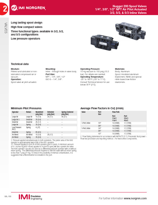
Materials:Body: Aluminum Spool: Anodized aluminumVALVES3/2 Air Pilot/Air Pilot5/2 Air Pilot /Spring Return3/2 Air Pilot/Spring Return Normally OpenSymbolModelPort Size Operator Pilot Port Size Operating Pressure Pilot Pressure Repair Kit K41DA00KA1KS61/4" NPT Small Air 1/8" NPT 10" Hg - 15065 - 15054237-59K41DA00KA2KS61/4" NPT Large Air1/8" NPT 10" Hg - 15035 - 15054237-59K41DA00KA6KS61/4" NPT Low Pressure Operator 1/8" NPT 10" Hg - 150 4 - 15054237-59K41DA00KA8KS61/4" NPT Air Bleed 1/8" NPT 10" Hg - 15035 - 15054237-59K41EA00KA1KS63/8" NPT Small Air 1/8" NPT 10" Hg - 15065 - 15054237-59K41EA00KA2KS63/8" NPT Large Air1/8" NPT 10" Hg - 15035 - 15054237-59K41EA00KA6KS63/8" NPT Low Pressure Operator 1/8" NPT 10" Hg - 150 4 - 15054237-59K41EA00KA8KS63/8" NPTAir Bleed1/8" NPT10" Hg - 15035 - 15054237-593/2 Air Pilot/Spring Return Normally ClosedSymbolModelPort Size Operator Pilot Port Size Operating Pressure Pilot Pressure Repair Kit K41DA00KS6KA11/4" NPT Small Air 1/8" NPT 10" Hg - 15065 - 15054237-59K41DA00KS6KA21/4" NPT Large Air1/8" NPT 10" Hg - 15035 - 15054237-59K41DA00KS6KA61/4" NPT Low Pressure Operator 1/8" NPT 10" Hg - 150 4 - 15054237-59K41DA00KS6KS81/4" NPT Air Bleed 1/8" NPT 10" Hg - 15035 - 15054237-59K41EA00KS6KA13/8" NPT Small Air 1/8" NPT 10" Hg - 15065 - 15054237-59K41EA00KS6KA23/8" NPT Large Air1/8" NPT 10" Hg - 15035 - 15054237-59K41EA00KS6KA63/8" NPT Low Pressure Operator 1/8" NPT 10" Hg - 150 4 - 15054237-59K41EA00KS6KS83/8" NPT Air Bleed 1/8" NPT 10" Hg - 15035 - 15054237-59SymbolModelPort Size Detented Operator Pilot Port Size Operating Pressure Pilot Pressure Repair Kit K41DA00KA1KA11/4" NPT Small Air 1/8" NPT 10" Hg - 15025 - 15054237-59K41DA00KA2KA21/4" NPT Large Air 1/8" NPT 10" Hg - 15015 - 15054237-59K41DA00KAAKAA 1/4" NPT YesLarge Air 1/8" NPT 10" Hg - 15025 - 15054237-59K41DA00KA1KA21/4" NPT Air Bias1/8" NPT 10" Hg - 15035 - 15054237-59K41DA00KA6KA61/4" NPT Low Pressure Operator 1/8" NPT 10" Hg - 150 1 - 15054237-59K41DA00KA8KA81/4" NPT Air Bleed 1/8" NPT 10" Hg - 15015- 15054237-59K41EA00KA1KA13/8" NPT Small Air 1/8" NPT 10" Hg - 15025 - 15054237-59K41EA00KA2KA23/8" NPT Large Air 1/8" NPT 10" Hg - 15015 - 15054237-59K41EA00KAAKAA 3/8" NPT YesLarge Air 1/8" NPT 10" Hg - 15025 - 15054237-59K41EA00KA1KA23/8" NPT Air Bias1/8" NPT 10" Hg - 15035 - 15054237-59K41EA00KA6KA63/8" NPT Low Pressure Operator 1/8" NPT 10" Hg - 150 1 - 15054237-59K41EA00KA8KA83/8" NPTAir Bleed1/8" NPT10" Hg - 15015- 15054237-59SymbolModelPort Size Operator Pilot Port Size Operating Pressure Pilot Pressure Repair Kit K71DA00KS6KA11/4" NPT Small Air 1/8" NPT 10" Hg - 15065 - 15054237-56K71DA00KS6KA21/4" NPT Large Air1/8" NPT 10" Hg - 15035 - 15054237-56K71DA00KS6KA61/4" NPT Low Pressure Operator 1/8" NPT 10" Hg - 150 4 - 15054237-56K71DA00KS6KA81/4" NPT Air Bleed 1/8" NPT 10" Hg - 15035 - 15054237-56K71EA00KS6KA13/8" NPT Small Air 1/8" NPT 10" Hg - 15065 - 15054237-56K71EA00KS6KA23/8" NPT Large Air1/8" NPT 10" Hg - 15035 - 15054237-56K71EA00KS6KA63/8" NPT Low Pressure Operator 1/8" NPT 10" Hg - 150 4 - 15054237-56K71EA00KS6KA83/8" NPT Air Bleed 1/8" NPT 10" Hg - 15035 - 15054237-56K71FA00KS6KA11/2" NPT Small Air 1/8" NPT 10" Hg - 15065 - 15054237-56K71FA00KS6KA21/2" NPT Large Air1/8" NPT 10" Hg - 15035 - 15054237-56K71FA00KS6KA61/2" NPT Low Pressure Operator 1/8" NPT 10" Hg - 150 4 - 15054237-56K71FA00KS6KA81/2" NPTAir Bleed1/8" NPT10" Hg - 15035 - 15054237-5624153213213213VALVES5/2 Double Air Pilot5/3 All Ports Blocked5/3 Center Open to Exhaust5/3 Center Open to PressureSymbolModelPort Size Detented Operator Pilot Port Size Operating Pressure Pilot Pressure Repair Kit K71DA00KA1KA11/4" NPT Small Air 1/8" NPT 10" Hg - 15025 - 15054237-56K71DA00KA2KA21/4" NPT Large Air 1/8" NPT 10" Hg - 15015 - 15054237-56K71DA00KAAKAA 1/4" NPT YesLarge Air 1/8" NPT 10" Hg - 15025 - 15054237-56K71DA00KA1KA21/4" NPT Air Bias1/8" NPT 10" Hg - 15035 - 15054237-56K71DA00KA6KA61/4" NPT Low Pressure Operator 1/8" NPT 10" Hg - 150 1 - 15054237-56K71DA00KA8KA81/4" NPT Air Bleed 1/8" NPT 10" Hg - 15015- 15054237-56K71EA00KA1KA13/8" NPT Small Air 1/8" NPT 10" Hg - 15025 - 15054237-56K71EA00KA2KA23/8" NPT Large Air 1/8" NPT 10" Hg - 15015 - 15054237-56K71EA00KAAKAA 3/8" NPT YesLarge Air 1/8" NPT 10" Hg - 15025 - 15054237-56K71EA00KA1KA23/8" NPT Air Bias1/8" NPT 10" Hg - 15035 - 15054237-56K71EA00KA6KA63/8" NPT Low Pressure Operator 1/8" NPT 10" Hg - 150 1 - 15054237-56K71EA00KA8KA83/8" NPT Air Bleed 1/8" NPT 10" Hg - 15015- 15054237-56K71FA00KA1KA11/2" NPT Small Air 1/8" NPT 10" Hg - 15025 - 15054237-56K71FA00KA2KA21/2" NPT Large Air 1/8" NPT 10" Hg - 15015 - 15054237-56K71FA00KAAKAA 1/2" NPT YesLarge Air 1/8" NPT 10" Hg - 15025 - 15054237-56K71FA00KA1KA21/2" NPT Air Bias1/8" NPT 10" Hg - 15035 - 15054237-56K71FA00KA6KA61/2" NPT Low Pressure Operator 1/8" NPT 10" Hg - 150 1 - 15054237-56K71FA00KA8KA81/2" NPTAir Bleed1/8" NPT 10" Hg - 15015- 15054237-56SymbolModelPort Size Operator Pilot Port Size Operating Pressure Pilot Pressure Repair Kit K81DA00KACKAC 1/4" NPT Large Air 1/8" NPT 10" Hg - 15045 - 15054237-56K81EA00KACKAC 3/8" NPT Large Air 1/8" NPT 10" Hg - 15045 - 15054237-56K81FA00KACKAC 1/2" NPT Large Air 1/8" NPT 10" Hg - 15045 - 15054237-56SymbolModelPort Size Operator Pilot Port Size Operating Pressure Pilot Pressure Repair Kit K81DA06KACKAC 1/4" NPT Large Air 1/8" NPT 10" Hg - 15045 - 15054237-58K81EA06KACKAC 3/8" NPT Large Air 1/8" NPT 10" Hg - 15045 - 15054237-58K81FA06KACKAC1/2" NPTLarge Air1/8" NPT10" Hg - 15045 - 15054237-58SymbolModelPort Size Operator Pilot Port Size Operating Pressure Pilot Pressure Repair Kit K81DA05KACKAC 1/4" NPT Large Air 1/8" NPT 10" Hg - 15045 - 15054237-57K81EA05KACKAC 3/8" NPT Large Air 1/8" NPT 10" Hg - 15045 - 15054237-57K81FA05KACKAC 1/2" NPT Large Air 1/8" NPT 10" Hg - 15045 - 15054237-5724153213213213VALVES3/2 Air Pilot/Spring Return Normally Open3/2 Air Pilot/Spring Return Normally Closed3/2 Air Pilot/Air Pilot5/2 Air Pilot /Spring Return5/2 Double Air Pilot5/3 All Ports BlockedSymbolModelPort Size Operator Pilot Port Size Operating Pressure Pilot Pressure Repair Kit K41DG00KA4KS61/4" ISO G Small Air 1/8" ISO G 10" Hg - 15065 - 15054237-59K41DG00KA5KS61/4" ISO G Large Air 1/8" ISO G 10" Hg - 15035 - 15054237-59K41EG00KA4KS63/8" ISO G Small Air 1/8" ISO G 10" Hg - 15065 - 15054237-59K41EG00KA5KS63/8" ISO G Large Air 1/8" ISO G 10" Hg - 15035 - 15054237-59SymbolModelPort Size Operator Pilot Port Size Operating Pressure Pilot Pressure Repair Kit K41DG00KS6KA41/4" ISO G Small Air 1/8" ISO G 10" Hg - 15065 - 15054237-59K41DG00KS6KA51/4" ISO G Large Air 1/8" ISO G 10" Hg - 15035 - 15054237-59K41EG00KS6KA43/8" ISO G Small Air 1/8" ISO G 10" Hg - 15065 - 15054237-59K41EG00KS6KA53/8" ISO G Large Air 1/8" ISO G 10" Hg - 15035 - 15054237-59SymbolModelPort Size Detented Operator Pilot Port Size Operating Pressure Pilot Pressure Repair Kit K41DG00KA4KA41/4" ISO G Small Air 1/8" ISO G 10" Hg - 15025 - 15054237-59K41DG00KA5KA51/4" ISO G Large Air 1/8" ISO G 10" Hg - 15015 - 15054237-59K41DG00KABKAB 1/4" ISO G YesLarge Air 1/8" ISO G 10" Hg - 15025 - 15054237-59K41DG00KA4KA51/4" ISO G Air Bias 1/8" ISO G 10" Hg - 15035 - 15054237-59K41EG00KA4KA43/8" ISO G Small Air 1/8" ISO G 10" Hg - 15025 - 15054237-59K41EG00KA5KA53/8" ISO G Large Air 1/8" ISO G 10" Hg - 15015 - 15054237-59K41EG00KABKAB 3/8" ISO G YesLarge Air 1/8" ISO G 10" Hg - 15025 - 15054237-59K41EG00KA4KA53/8" ISO GAir Bias 1/8" ISO G 10" Hg - 15035 - 15054237-59SymbolModelPort Size Operator Pilot Port Size Operating Pressure Pilot Pressure Repair Kit K71DG00KS6KA41/4" ISO G Small Air 1/8" ISO G 10" Hg - 15065 - 15054237-56K71DG00KS6KA51/4" ISO G Large Air 1/8" ISO G 10" Hg - 15035 - 15054237-56K71EG00KS6KA43/8" ISO G Small Air 1/8" ISO G 10" Hg - 15065 - 15054237-56K71EG00KS6KA53/8" ISO G Large Air 1/8" ISO G 10" Hg - 15035 - 15054237-56K71FG00KS6KA41/2" ISO G Small Air 1/8" ISO G 10" Hg - 15065 - 15054237-56K71FG00KS6KA51/2" ISO G Large Air 1/8" ISO G 10" Hg - 15035 - 15054237-56SymbolModelPort Size Detented Operator Pilot Port Size Operating Pressure Pilot Pressure Repair Kit K71DG00KA4KA41/4" ISO G Small Air 1/8" ISO G 10" Hg - 15025 - 15054237-56K71DG00KA5KA51/4" ISO G Large Air 1/8" ISO G 10" Hg - 15015 - 15054237-56K71DG00KABKAB 1/4" ISO G YesLarge Air 1/8" ISO G 10" Hg - 15025 - 15054237-56K71DG00KA4KA51/4" ISO G Air Bias 1/8" ISO G 10" Hg - 15035 - 15054237-56K71EG00KA4KA43/8" ISO G Small Air 1/8" ISO G 10" Hg - 15025 - 15054237-56K71EG00KA5KA53/8" ISO G Large Air 1/8" ISO G 10" Hg - 15015 - 15054237-56K71EG00KABKAB 3/8" ISO G YesLarge Air 1/8" ISO G 10" Hg - 15025 - 15054237-56K71EG00KA4KA53/8" ISO G Air Bias 1/8" ISO G 10" Hg - 15035 - 15054237-56K71FG00KA4KA41/2" ISO G Small Air 1/8" ISO G 10" Hg - 15025 - 15054237-56K71FG00KA5KA51/2" ISO G Large Air 1/8" ISO G 10" Hg - 15015 - 15054237-56K71FG00KABKAB 1/2" ISO G YesLarge Air 1/8" ISO G 10" Hg - 15025 - 15054237-56K71FG00KA4KA51/2" ISO GAir Bias1/8" ISO G10" Hg - 15035 - 15054237-56SymbolModelPort Size Operator Pilot Port Size Operating Pressure Pilot Pressure Repair Kit K81DG00KADKAD 1/4" ISO G Large Air 1/8" ISO G 10" Hg - 15045 - 15054237-56K81EG00KADKAD 3/8" ISO G Large Air 1/8" ISO G 10" Hg - 15045 - 15054237-56K81FG00KADKAD 1/2" ISO G Large Air 1/8" ISO G 10" Hg - 15045 - 15054237-562132415324153213213213VALVES5/3 Center Open to Exhaust5/3 Center Open to PressureSymbolModelPort Size Operator Pilot Port Size Operating Pressure Pilot Pressure Repair Kit K81DG06KADKAD 1/4" ISO G Large Air 1/8" ISO G 10" Hg - 15045 - 15054237-58K81EG06KADKAD 3/8" ISO G Large Air 1/8" ISO G 10" Hg - 15045 - 15054237-58K81FG06KADKAD 1/2" ISO G Large Air 1/8" ISO G 10" Hg - 15045 - 15054237-58SymbolModelPort Size Operator Pilot Port Size Operating Pressure Pilot Pressure Repair Kit K81DG05KADKAD 1/4" ISO G Large Air 1/8" ISO G 10" Hg - 15045 - 15054237-57K81EG05KADKAD 3/8" ISO G Large Air 1/8" ISO G 10" Hg - 15045 - 15054237-57K81FG05KADKAD 1/2" ISO G Large Air 1/8" ISO G 10" Hg - 15045 - 15054237-57Replacement PartsModel Pilot Port size Description Positions KA11/8" NPT Small Air 2-position KA21/8" NPT Large Air2-position KA61/8" NPT Low Pressure Air 2-position KA81/8" NPT Air Bleed2-position KAA 1/8" NPT Large Air Detented 2-position KAC 1/8" NPT Large Air 3-postion KA41/8" ISO G Small Air 2-position KA51/8" ISO G Large Air2-position KAB 1/8" ISO G Large Air Detented 2-position KAD 1/8" ISO GLarge Air 3-postioon KS6Spring Return2-position.52(13.2)1/8-27 PTF or G 1/8 ISOKA1, KA4SMALL AIR (AIR BIAS).85(21.6)1/8-27 PTF or G 1/8 ISO (2 Places)KA6, KA7LOW PRESSURE4.53(115.0)1.25(31.8)KA6 Low Pressure Operator(inline valves only)Operator shifts the valve spool with only 4 psig (.28 bar) applied to Port B (Port A open). A minimum vacuum of 6.1" Hg (with KS1 spring return) applied to port A (Port B open) will also operate the valve. Can also be used as a differential pressure operator with or without spring return.KA1 Air Bias OperatorWhen pressure is applied to the KA1 operator the valve spool shifts to the KA2 end. When pressure is applied to both the KA1 and KA2 operators the valve spool shifts to the KA1 end.1.16(29.5)1.51(38.4).59(15.0)KAA/KAF KA2, KA5KA8, KA9LARGE AIR1/8-27 PTF or G 1/8 ISO Air Bleed Operators Constantly bleeds a smallamount of air to atmosphere. The valve spool shifts when air bleed is stopped by a customer-supplied on-off valve.Dimensions in inches (mm)213213VALVESReplacement PartsNTP ISO G Thread FunctionPort Size Replacement Spool K41DA00K41DG003-ported / 2 position 1/4"54237-59K41ED00K41ED003-ported / 2 position 3/8"54237-59K71DA00K71DG005-ported / 2 position 1/4"54237-56K71EA00K71EG005-ported / 2 position 3/8"54237-56K71FA00K71FG005-ported / 2 position1/2"54237-56K81DA00K81DG005-ported / 3 position APB 1/4"54237-56K81EA00K81EG005-ported / 3 position APB 3/8"54237-56K81FA00K81FG005-ported / 3 position APB 1/2"54237-56K81DA06K81DG065-ported / 3 position COE 1/4"54237-58K81EA06K81EG065-ported / 3 position COE 3/8"54237-58K81FA06K81FG065-ported / 3 position COE 1/2"54237-58K81DA05K81DG055-ported / 3 position COP 1/4"54237-57K81EA05K81EG055-ported / 3 position COP 3/8"54237-57K81FA05K81FG055-ported / 3 position COP1/2"54237-57Inline Bodies2.48 (63.0).56(14.2).56(14.2)31012211.08(27.4).84(21.3)2.16(54.8).69(17.5).69(17.5)MOUNTING HOLES .26 (6.6) DIA.(2 Places)1/4 or 3/8 PTF G 1/4 or G 3/8 ISO(3 Places)1.24 (31.5)1.26(32.0)3-WAY – 1/4" & 3/8" PORTSK411451223141.08(27.4).84(21.3)2.16(54.8)1.26(32.0)3.54 (89.9)1.09(27.7)1.09(27.7)4-WAY – 1/4", 3/8", 1/2" PORTSK71 or K811.10(27.9)1.10(27.9).26 (6.6) DIA.(2 Places)1/4, 3/8 or 1/2 PTF G 1/4 or G 3/8 ISO(5 Places)1.77 (45.0).55(14.0).55(14.0)Dimensions in inches (mm)。
进口压力——精选推荐

CT 269/C调压器NORVALNORVAL+I-N+ERNORVALERPL进口压力出口压力LPP调压器NORVAL说 明主要特性供货规格1 NORVAL 燃气调压器是由膜片(薄膜)和弹簧控制的直接作用式调压器,适用于中,低压燃气的调压。
除用于输配管网及灶,燃具供气外,由于其结构简单,响应迅速,可靠性高等优点,还特别适用于流量剧变,上游压力常有波动的用户(锅炉,燃气炉等)。
NORVAL 调压器适用于经过滤净化的非腐蚀性气体,包括天燃气,人工煤气,液化石油气,混合气等。
阀系数 Cg 大调压精度高响应迅速无流量时完全密封可用作监控器故障时开启顶部装入结构,在线维修方便可加装内装式紧急切断阀主要性能设计压力:1.9MPa工作温度范围:-20 ̄60℃(可更高或更低)环境温度:-20 ̄60℃进口压力范围 bPe:DN25 ̄80 0.01 ̄1.6MPaDN100 ̄200 0.01 ̄0.8MPa : ℃℃调压范围WhDN25 ̄1000.8 ̄440kPaDN150 ̄2001.2 ̄180kPa精度等级RG:高达 5关闭压力等级SG:高达 10DN 25、32、40、50、65、80、100、150、200法兰连接尺寸:ANSI 150 RF B16.5 PN16RF UNI2282、DIN2633、GB9119.8图 1 NORVAL 工作原理调压器NORVAL结构及工作原理2 NORVAL 调压器由阀主体及装有膜片(薄膜)及弹簧的头部组成。
每一种直径的阀主体可有几种不同直径的头部配以不同刚度的弹簧以适应不同的出口压力值。
出口压力由引压管 1(图 1)引入作用在膜片 3 上,此力与膜片另一侧的弹簧力相平衡。
平衡位置决定了阀的开度,从而有一定的流量。
运行中如流量需求增加或进口压力下降,调压器出口压力就会随之有所降低,膜片上所受燃气压力作用的力减小,膜片 3 及与其相连的阀瓣 5 在弹簧 2 作用下向下移动将阀开大,促使流量增加进而使出口压力恢复,反之,如流量需求减小,或进口压力增大,阀会自动关小,从而维持出口压力不变。