dc使用 design compiler
DC综合教程

DC操作流程
1.在虚拟机中 打开终端
DC操作流程 2. 创建综合 环境 在终端输入: new_dc xxx
xxx为你想要创 建的文件夹的名 字
DC操作流程
3. 修改环境(参考Readme
文件)
a.修改filelist.tcl 添加通过验证的源代 码
DC操作流程
b.修改synopsys.sdc 添加综合约束
DC 工具简要入门
2012年秋
内容
• 1. 逻辑综合以及综合工具
Design Compile • 2.DC操作流程
• 3.现场演示
逻辑综合
• 将RTL代码转换为门级网表 的过程
逻辑综合
DC工具
• Design Compile是常用的综合 工具,在DC中,共有8中设计 实体 • 1、设计(Design):一种能 完成一定逻辑功能的电路。设 计中可以包含子设计
• 对于DC而言,通常要指定下面4种库 • 1、Target library 工艺库,由代工厂提供的和具体工艺 相关的工艺库 • 2、Link library 指定DC查找时所指定的目标,通常 也就是Target library
DC工具--指定参考库
• Synthetic library DC综合时将转化HDL代码为相应元 件时所参考的IP库。比如符号“+”, 通过IP库查找生成某类加法器。默认 使用自带的加法库。 • Symbol library 使用图形界面时,在原理图上绘制 与非门等标准单元的符号库
DC工具
• 2、单元(Cell):子设计的实例 • 3、参考(Reference):单元的参考对 象,即单元是参考的实例 • 4、端口(Port) • 5、管脚(Pin) • 6、线网(Net) • 7、时钟(Clock) • 8、库(Library):综合时用到的一组基 本单元的集合
DesignCompiler一般问题解答
DesignCompiler一般问题解答Design Compiler 一般问题解答1.1 什么是DC?DC(Design Compiler)是Synopsys公司的logical synthesis工具,它根据design description 和design constraints自动综合出一个优化了的门级电路。
它可以接受多种输入格式,如HDL、Schematics、Netlist等,并能生成多种性能report,在reducing design time的同时提高了设计的性能。
1.2 DC能接受多少种输入格式?支持.db、.v、.vhd、.edif、.vgh、.lib等,.db一般是厂商的单元库;.v是veilog的后缀;.vhd 是VHDL的后缀;.edif 和.vhd是两种形式的netlist。
1.3 DC提供多少种输出格式?提供.db、.v、.vhd、edif、.vgh等,并可以输出sdc、sdf等相关格式文件。
1.4 DC的主要功能或者主要作用是什么?DC是把HDL描述的电路综合为跟工艺相关的门级电路。
并且根据用户的设计要求,在timing、area、power上取得最佳的效果。
在floorplanning和placement和插入时钟树后返回DC进行时序验证。
1.5 如何寻找帮助?帮助可以用3种求助方式:1. 使用SOLD,到文档中寻求答案2. 在命令行中用man+ DC命令(我最喜欢这种)3. 在命令行中用info+ DC命令1.6 如何找到SOLD文档?SOLD文档可以在teminal中输入sold&执行。
$> sold&或者用命令which dc_shell找到dc的安装目录。
找到online目录。
1.7 如何配置DC?综合设置提供必要的参数给DC,使工具能够知道进行综合时所需要的必要的信息,如:工艺库,目标库,标志库等等。
要在.synopsys_dc.setup上设置好这些参数。
SynopsysDesignCompiler使用
SynopsysDesignCompiler使⽤Synopsys Design Compiler使⽤⼀、介绍:美国Synopsys公司发布的“Design Compiler”软件,简称“DC”,是⼀种逻辑合成⼯具。
通过改进电路延迟时间的计算⽅法,缩⼩了逻辑合成时的时序与布局完成后的最终时序之间的偏差。
DC得到全球60多个半导体⼚商、380多个⼯艺库的⽀持。
据最新Dataquest的统计,Synopsys的逻辑综合⼯具占据91%的市场份额。
DC是⼗⼆年来⼯业界标准的逻辑综合⼯具,也是Synopsys最核⼼的产品。
它使IC设计者在最短的时间内最佳的利⽤硅⽚完成设计。
它根据设计描述和约束条件并针对特定的⼯艺库⾃动综合出⼀个优化的门级电路。
它可以接受多种输⼊格式,如硬件描述语⾔、原理图和⽹表等,并产⽣多种性能报告,在缩短设计时间的同时提⾼设计性能。
⼆、要求:由于实训没有硬性要求VHDL⽂件,本⼈挑选了已经预先做好的洗⾐机时控电路,利⽤Synopsys Design Compiler⼯具,进⾏优化分析,通过这⼀过程熟悉软件的使⽤。
三、过程:设置优化运⾏库,鉴于⽼师在练习⼿册上⾯提供的例⼦,我们使⽤库LSI-10K,因此在打开VHDL⽂件前,需要作以下设置Setup->Defaults,填⼊以下信息。
在File->read打开要分析优化的VHDL⽂件,这⾥我选择⼀个洗⾐机时控电路NewWasher.vhd 如下所⽰(分别为不同层次的视图:顶层、器件、门级电路)在Tools->Design Optimization中设置好兼顾平衡的约束条件(左图),确定编译后,产⽣了右边经过优化的门级电路图。
接下来,把优化过的图形转换为VHDL⽂件和DB⽂件输出,另存到指定位置File->Save As如右图,⽣成了新的DB⽂件和vhd⽂件。
接下来,是要设定CLK的周期,根据分析、优化、编译出来的Slack Time 松弛数值和Area⾯积数值,选取最合适的平衡点。
使用Design Compiler进行电路综合
使用Design Compiler进行电路综合——By WangJZ magic14@2011-4-19 本文以一个简单设计为例,介绍Synopsys公司的综合工具Design Compiler(以下简称DC)的基本使用流程。
DC综合过程可划分为三个部分:一,读取设计文件,将设计代码转换为DC自带的基本逻辑单元表示的门电路;二,设计者对设计进行约束,包括时序约束和面积约束;三,DC根据设计者提供的约束,对电路进行优化,并映射为流片厂家工艺库逻辑门表示的电路。
下面是具体步骤:工程目录为存放在用户文件夹下的dc_phy文件夹,该工程包括4个用verilog语言编写的代码文件,存放在工程目录的scr文件夹里,其中phy_utmi为顶层文件,其余为子模块。
设置环境变量,进入工程目录,用dc_shell命令启动DC,如下图所示。
使用set search_path命令设置搜索路径,用set target_library命令设置目标库(流片厂所提供的工艺库)所在路径,用set link_library命令设置链接库路径,如下图所示。
用read_verilog命令读取设计文件,虽然设计文件并不在当前目录dc_phy中,但由于设置了搜索路径(set search_path “$ search_path ./scr”),所以DC仍能找scr文件夹中的设计文件,如下图所示。
用current_design命令告知DC,设计的顶层模块为phy_utmi,并用link命令链接到工艺库,如下图所示:对设计进行时序约束和面积,由于本设计比较简单,所以仅进行几个简单约束作为演示。
约束完后使用compile命令进行综合,如下图所示:综合完成后,使用write命令输出门级网表,使用write_sdc命令输出设计约束,获取门级网表和约束文件后,就可以使用Cadence公司的Encounter软件进行自动布局布线了。
过程如下图所示。
DC Design Compiler 综合脚本命令及参考模板
Design Compiler 综合脚本常用命令和模板参照自己的设计,以及自己的工艺信息,适当修改下面的Constraints和Run Script 等的脚本,添加一些相关的约束语句,就可以运行了详细的命令请参照DC的官方User Guide等相关资料。
Invoking Design CompilerUnix% design_vision # Interactive GUI, WLM modeUnix% design_vision –topographical # Interactive GUI, Topographical modeUnix% dc_shell-t # Interactive shell, WLM modeUnix% dc_shell-t –topographical # Interactive shell, Topographical modeUnix% dc_shell-t –f RUN.tcl | tee –i my.log # Batch mode.synopsys_dc.setupset search_pa th “$search_path libs cons unmapped rtl”set synthetic_library dw_foundation.sldbset target_library 65nm.dbset link_library “* $target_library $synthetic_library IP.db”set symbol_library 65nm.sdbdefine_design_lib WORK –path ./workset_svf <my_filename.svf>set_vsdc <my_filename.vsdc>history keep 200set sh_enable_page_mode falseset cache_write .set cache_read $cache_writesuppress_message {LINT-28 LINT-32 LINT-33 UID-401}set alib_library_analysis_path [get_unix_variable HOME]alias h historyalias rc “report_constraint -all_violators”TCL Commands and Constructsset PER 2.0 # Define a variable and its valueecho $PER # Variable substitution → 2.0set MARG 0.95expr $PER * $MARG # expr: *, /, +, -, >, <, =, <=, >=set pci_ports [get_ports A] # Imbedded commandset pci_ports [get_ports “Y??M Z*”]# Wildcardsecho “Effctv P = \ # Soft quotes → 1.9[expr $PERIOD * $MARGIN]”echo {Effctv P = \ # Hard quotes[expr $PERIOD * $MARGIN]} # → Effctv P = [expr $PER * $MARG] # Comment lineset COMMENT in_line; # In-line commentset MY_DESIGNS {B1.v ... B26.v} # foreach loopforeach DESIGN $MY_DESIGNS {read_verilog $DESIGN}for {set i 1} {$i < 27} {incr i} { # for loopread_verilog BLOCK_$i.v}Helpful UNIX-like DC-shell commandspwdcdlshistory!!!7!reportsh <UNIX_command>printenvget_unix_variable ARCHConstraintsreset_designset_max_area 0create_clock -period 2 –name Main_Clk [get_ports Clk1]create_clock –period 2.5 –waveform {2 3.5} [get_ports Clk2]create_clock –period 3.5 –name V_Clk; # VIRTUAL clockset_clock_uncertainty –setup 0.14 [get_clocks *]set_clock_uncertainty –setup 0.21 –from [get_clocks Main_Clk] –to [get_clocks Clk2]set_clock_latency –max 0.6 [get_clocks Main_Clk]set_clock_latency –source –max 0.3 [get_clocks Main_Clk]set_clock_transition 0.08 [get_clocks Main_Clk]set_input_delay -max 0.6 -clock Main_Clk [all_inputs]set_input_delay –max 0.3 –clock Clk2 –clock_fall –add_delay [get_ports “B E”]set_input_delay -max 0.5 -clock –network_latency_included V_Clk [get_ports “A C F”]set_output_delay -max 0.8 -clock –source_latency_included Main_Clk [all_outputs]set_output_delay -max 1.1 -clock V_Clk [get_ports “OUT2 OUT7]set_max_capacitance 1.2 [all_inputs]set_load 0.080 [all_outputs]set_load [expr [load_of slow_proc/NAND2_3/A] * 4] [get_ports OUT3]set_load 0.12 [all_inputs]set_input_transition 0.12 [remove_from_collection [all_inputs][get_ports B]]set_driving_cell –lib_cell FD1 –pin Q [get_ports B]set_operating_conditions –max WCCOMset auto_wire_load_selection falseset_wire_load_model –name 1.6MGatesset_wire_load_mode enclosedset_wire_load_model –name 200KGates [get_designs “SUB1 SUB2”]set_wire_load_model –name 3.2MGates [get_ports IN_A]set_port_fanout_number 8 [get_ports IN_A]set_false_path -from [get_clocks Asynch_CLKA] -to [get_clocks Asynch_CLKB]set_multicycle_path –setup 4 –from –from A_reg -through U_Mult/Out –to B_regset_multicycle_path –hold 3 –from –from A_reg -through U_Mult/Out –to B_regset_isolate_ports –type inverter [all_outputs]set_ideal_network [get_ports reset* select*]set_ideal_network [get_pins FF_SET_reg/Q]set_ideal_network –no_propagate [get_nets CTRL]set_ideal_latency 1.4 [get_ports reset* select*]set_ideal_transition 0.5 [get_pins FF_SET_reg/Q]set_scan_configuration -style <multiplexed_flip_flop | clocked_scan | lssd | aux_clock_lssd>Checking and Removing Constraints and Directivesreport_clock; report_clock -skewreport_designreport_port –verbosereport_wire_loadreport_path_groupsreport_timing_requirements (–ignored)report_auto_ungroupreport_isolate_portswrite_script –output <constraints.tcl>check_timingreset_path –from FF1_regremove_clockremove_clock_transitionremove_clock_uncertaintyremove_input_delayremove_output_delayremove_driving_cellremove_wire_load_modelSyntax CheckingUnix% dcprocheck constr_file.conPhysical Constraints – Topographical Modeset_aspect_ratioset_utilizationset_placement_areaset_rectilinear_outlineset_port_sideset_port_locationset_cell_locationcreate_placement_keepoutMisc. Reports# Generate A library report fileread_db library_file.dblist_libsredirect –file reports/lib.rpt {report_lib <libname>} report_hierarchy [-noleaf]# Arithmetic implementation and# resource-sharing inforeport_resources# List area for all cells in the designreport_cell [get_cells –hier *]Run Scriptread_verilog {A.v B.v TOP.v} orread_vhdl {A.vhd B.vhd TOP.vhd} orread_ddc MY_TOP.ddc oracs_read_hdl MY_TOP oranalyze –format verilog {A.v B.v TOP.v}elaborate MY_TOP –parameters “A_WIDTH=8, B_WIDTH=16”current_design MY_TOPlinkif {[check_design] ==0} {echo “Check Design Error”exit # Exits DC if a check-design error is encountered} # Continue if NO problems encounteredwrite –f ddc –hier –out unmappedd/TOP.ddcredirect –tee –file reports/precompile.rpt {source –echo -verbose TOP.con}redirect –append –tee –file reports/precompile.rpt {check_timing}source <Physical_Constraints_TCL_file> or # Source tcl constraints, if available, or extract_physical_constraints <DEF_file> # Extract and apply from an existing # DEF floorplan filegroup_path -name CLK1 -critical_range <10% of CLK1 Period> –weight 5group_path -name CLK2 -critical_range <10% of CLK2 Period> –weight 2group_path –name INPUTS –from [all_inputs]group_path –name OUTPUTS –to [all_outputs]group_path –name COMBO –from [all_inputs] –to [all_outputs]set_fix_multiple_port_nets –all –buffer_constants********************************************************** ** Insert Expert, Ultra or ACS compile flow here ** **********************************************************check_designreport_constraint –all_violatorsreport_timing –delay –to –from –through –input_pins –max_paths \–nworst –nets –cap –sig –groupreport_areareport_qorset verilogout_no_tri truechange_names –rule verilog –hierwrite –f verilog –hier –out mapped/TOP.vwrite –f ddc –hier –out mapped/TOP.ddcwrite_sdc TOP.sdcwrite_scan_def –out TOP_scan.defwrite_physical_constraints –output TOP_PhysConstr.tcl exitObject Retrieval and Manipulation (Collection Commands) get_ports, get_pins, get_designsget_cells, get_nets, get_clocksget_nets –of_objects [get_pins FF1_reg/Q]get_libs <lib_name>get_lib_cells <lib_name/cell_names>get_lib_pins <lib_name/cell_name/pin_names>all_inputs, all_outputs, all_clocks, all_registersall_connectedall_fanin, all_fanoutall_ideal_netsset pci_ports [get_ports pci_*]echo $pci_ports # → _sel184 query_objects $pci_ports # → {pci_1 pci_2 ...} get_object_name $pci_ports # → pci_1 pci_2 ... sizeof_collection $pci_ports # → 37set pci_ports [add_to_collection $pci_ports \[get_ports CTRL*]]set all_inputs_except_clk [remove_from_collection \ [all_inputs] [get_ports CLK]]compare_collectionsindex_collectionsort_collectionforeach_in_collection my_cells [get_cells -hier * \ -filter “is_hierarchical == true”] {echo “Instance [get_object_name $cell] is hierarchical”}# Filtering operators: ==, !=, >, <, >=, <=, =~, !~filter_collection [get_cells *] “ref_name =~ AN*”get_cells * -filter “dont_touch == true”get_clocks * -filter “period < 10”# List all cell attributes and redirect output to a fileredirect –file cell_attr \{list_attributes –application –class cell}# Grep the file for cell attributes starting with dont_UNIX% grep dont_ cell_attr | more# List the value of the attribute dont_touchget_attribute <cell_name> dont_touchUltra Compile Flow - Topographical or WLM ModeUltra + DesignWare and DFTC licenses available# In “topo” mode (dc_shell-t –topo) specify Milkyway reference and design libraries create_mw_lib –tech <technology_file> -mw_reference_library <mw_reference_libraries> \<mw_design_library_name>open_mw_lib <mw_design_library_name>set_tlu_plus_files -max_tluplus <max_tluplus_file> -tech2itf_map <mapping_file>set compile_auto_ungroup_delay_num_cells 99999999set compile_auto_ungroup_count_leaf_cells trueset compile_auto_ungroup_override_wlm trueset_ungroup <top_level_and/or_pipelined_blocks> false# OPTIONAL: Disable unconditional auto-ungrouping# of DesignWare hierarchy (not usually recommended)set compile_ultra_ungroup_dw false# If design contains pipelined sub-designs and the pipeline registers# are grouped together at the input or output, relax timingset_multicycle_path –setup <#_stages> -from U_Pipeline/R3_reg* –to U_Pipeline/R7_reg* # In “ topo” mode, if the floorplan is available, apply or extract the physical constraints source <physical_constraints_file> ORextract_physical_constraints <DEF_file># OPTIONAL: Exclude specific cells/design from adaptive retiming (-retime)set_dont_retime <cells_or_designs> true# First compilecompile_ultra –scan –retime –timing|-area# The design hierarchy may have changed due to auto-ungrouping/-uniquifyingreset_path -from U_Pipeline/R3_reg* -to U_Pipeline/R7_reg*# OPTIONAL: Maintain registered pipeline outputs if requiredset_dont_touch [get_cells U_Pipeline/R12_reg*] true# Optimize registers if pipeline violates timing; Skip if no pipeline issues:set_optimize_registers true –design My_Pipeline_Subdesignoptimize_registers –only_attributed_designs# Continue if design is NOT meeting all constraints:# Apply more focus on violating critical paths, as necessarygroup_path –name <group_name> -from <path_start> -to <path_end> \–critical range <10% of max delay goal> -weight 5# Select appropriate second compile# In “topo” mode in DC v2006.06, or any mode in DC v2007.03 or latercompile_ultra –scan –incremental# In “WLM” mode in DC v2006.06set_ultra_optimization truecompile –boundary –scan –map_effort high –incremental (-area_effort medium|low|none) # In “topo” mode prior to DC v2007.03: Write out updated physical constraintswrite_physical_constraints –output PhysConstr.tclDFT Flow – Expert or UltraDFTC license available# Prior to the first compile set the# scan cell styleset_scan_configuration –style ..# Perform the first test-ready compilecompile –boundary –map high –scan # ORcompile_ultra –timing -scan# Continue before the next compile:# Read in the scan specification filesource scan_spec.tcl# Check for DFT rule violationsdft_drc# Preview the scan chainspreview_dft# Insert and optimize scaninsert_dft******************************************************* * * Execute additional Ultra/Expert optimization ** techniques, as needed ** * ******************************************************# After the final compile check the DFT QoR# and write out the scan DEF filedft_drc –coverage_estimatewrite_scan_def -out <my_design.def>Some Scan Specification Commandsset_scan_state test_readyset_dft_configuration ...set_dft_signal ...set_scan_path ...set_scan_configuration ...create_test_protocolExpert Compile FlowNo Ultra license available; DFTC license availablecompile –boundary –scan –map_effort high# Continue if NOT meeting constraints# Note: -scan requires DFTC licensecompile –boundary –scan –map_effort high –incremental \ (-area_effort medium|low|none)# Continue if NOT meeting constraints:# Increase max-delay priority if OK to postpone DRC fixingset_cost_priority –delay# Note: The design hierarchy may have changed due to auto- # uniquifying# Apply more focus on violating critical paths, as necessary group_path –name <group_name> -from <path_start> \-to <path_end> –critical range <10% of max delay goal> -weight 5 # Repartition if design is poorly partitionedgroup –design <NEW_DESIGN> -cell_name <U_NEW_CELL> \{U2 U7 ...}ungroup –start_level 2 U_NEW_CELLcompile –boundary –scan –map_effort high –incremental \ (-area_effort medium|low|none)# Or, can ungroup all hierarchy in lieu of group/ungroup# commands with –ungroup_allcompile –boundary –scan –map_effort high –incremental \ (-area_effort medium|low|none) –ungroup_all“Pseudo Ultra” Compile FlowUltra license available; No DesignWare license availableset compile_auto_ungroup_delay_num_cells 99999999set compile_auto_ungroup_area_num_cells 99999999set compile_auto_ungroup_count_leaf_cells trueset compile_auto_ungroup_override_wlm trueset_ungroup <top_level_and/or_pipelined_blocks> false# OPTIONAL: Disable unconditional auto-ungrouping# of DesignWare hierarchy (not usually recommended)set compile_ultra_ungroup_dw false# If design contains pipelined sub-designs and the pipeline registers# are grouped together at the input or output, relax timingset_multicycle_path –setup <#_stages> \-from U_Pipeline/R3_reg* –to U_Pipeline/R7_reg*# Enable Ultra optimizations available for compileset_ultra_optimization –no_auto_dwlib trueset hlo_disable_datapath_optimization trueset compile_slack_driven_buffering truecompile –boundary –scan –map_effort high –auto_ungroup delay|area \ (-area_effort medium|low|none)# Note: The design hierarchy may have changed due to auto-# ungrouping and auto-uniquifyingreset_path -from U_Pipeline/R3_reg* -to U_Pipeline/R7_reg*# OPTIONAL: Maintain registered pipeline outputs if requiredset_dont_touch [get_cells U_Pipeline/R12_reg*] true# Optimize registers if pipeline violates timing; Skip if no pipeline issues:set_optimize_registers true –design My_Pipeline_Subdesignoptimize_registers –only_attributed_designs# Continue if design is NOT meeting all constraints:compile –boundary –scan –map_effort high –incremental \ (-area_effort medium|low|none)# Continue if NOT meeting all constraints:set_cost_priority –delay# Ungroup DesignWare components amid combinational logicungroup <DesignWare_components># Apply more focus on violating critical paths, as necessarygroup_path –name <group_name> -from <path_start> -to <path_end> \–critical range <10% of max delay goal> -weight 5compile –boundary –scan –map_effort high –incremental \ (-area_effort medium|low|none)。
design-compiler的安装和使用资料
的,该文件在scl目录下)
的实际路劲
修改主机名
用记事本打开“synopsys.dat”,将第一行修改为:SERVER 主机名 MAC地址 27000。其中主机名是Linux系统下的主机名,可在Linux的终端中用“uname -a”命 令查看,默认一般为“localhost.localdomain”;MAC地址就是网卡地址,后面的 27000是默认需要的。本文中该行信息为“SERVER localhost.localdomain 000c2916d785 27000”
Design_Compiler_2008.09_common.tar
Design_compiler_2008.09_linux.tar 3.安装DC2008需要用到SCL软件包
scl_v10.9.3_common.tar
scl_v10.9.3_linux.tar 4.安装平台 在linux4.6上安装(如果要使用虚拟机,则使用vmware6.5,使用虚拟机有 很多方便,可以在虚拟机中随时读取windows下的文件,资料复制都很方便 (可以直接往linux系统里面拖资料!),而且对于在只有一台电脑的情况下, 可以利用windows平台查看课件,查资料等)
3.利用KeyGen得到得到FEATURE SSS信息 ,运行“KeyGen.exe”,在“SECRET DATA” 栏中填入得到的SECRET DATA码,在“HOST ID”中填入你的MAC地址。
我们刚才得到的SECRET DATA
你的MAC地址
点击Generate后,会在此文件夹中生成一个license.dat的文件。
众多,为了方便,最好分类安放,下面是我文件夹内部的目录结构,仅供参考以 及便于后面的说明。建议安装的时候也参考这样。
DC使用说明
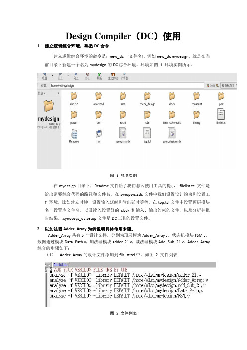
Design Compiler(DC)使用1.建立逻辑综合环境,熟悉DC命令建立逻辑综合环境的命令是:new_dc [文件名],例如new_dc mydesign,就是在当前目录下新建一个名为mydesign的DC综合环境。
环境如图1 环境实例所示。
图1 环境实例在mydesign目录下,Readme文件给了我们怎么使用工具的提示;filelist.tcl文件是给出需要综合代码的路径和文件名。
在synopsys.sdc文件中我们设置设计约束和设置工作环境,比如建立时钟,设置输入延时和输出延时等等。
在top.tcl文件中设置顶层模块名,设置库文件名,以及读入设置好的clock和输入、输出约束的文件,以及分析并报告结果。
.synopsys_dc.setup文件是DC工具的设置文件。
2.以加法器Adder_Array为例说明具体使用步骤。
Adder_Array共有5个设计文件,分别为顶层模块Adder_Array.v,状态机模块FSM.v,数据通过模块Data_Path.v,加法器模块adder_21.v,减法器模块Add_Sub_21.v。
Adder_Array 综合的步骤如下:(1)Adder_Array的设计文件添加到filelist.tcl中。
如图2 文件列表图2 文件列表(2)在top.tcl中将顶层模块设置为Adder_Array。
如图3修改顶层模块名图3 修改顶层模块名(3)修改synopsys.sdc实现以下设计约束:时钟周期1.2ns,input_delay设置为0.5ns,output_delay设置为0.5ns。
如果使用者想增加其他的设计约束可以在此文件中增添。
(4)进入刚才建好的综合环境,在终端中执行run命令,调用Design Compiler执行逻辑综合。
打开终端:cd [建好的环境路径],进入后输入run,即可。
(5)等逻辑综合执行完毕后,查看123.log,对其中的error和warning进行确认,如果有问题修改设计或综合脚本后重新综合,直至没有问题。
Design Complier 使用详解
1DC 概论之一setup time与hold time(1)ic代码的综合过程可以说就是时序分析过程,dc会将设计打散成一个个路经,这些路经上有cell延迟和net延迟,然后dc会根据你加的约束,来映射库中符合这种延迟以及驱动的器件。
从而达到综合的目的。
dc的所有时序约束基础差不多就是setup time 和 hold time。
可以用下面的图片说明:所谓setup time即建立时间,也就说数据在时钟到来之前保持稳定所需要的时间,hold time 即保持时间,也就是说在时钟到来之后数据需要保持稳定的时间。
在深入建立时间和保持时间之前。
先了解下dc中的路经以及start point ,end point。
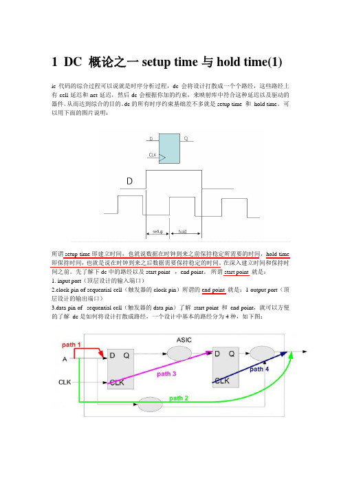
所谓start point 就是:1. input port(顶层设计的输入端口)2.clock pin of sequential cell(触发器的clock pin)所谓的end point 就是:1 output port(顶层设计的输出端口)3.data pin of sequential cell(触发器的data pin)了解 start point 和 end point,就可以方便的了解 dc是如何将设计打散成路经,一个设计中基本的路经分为4种,如下图:path1:input port to data pin of sequential cellpath2:input port to output portpath3:clock pin to data pin of next sequential cellpath4:clock pin to output port所有的设计也就这四种类型的路径。
另外一种就是带反馈的,也就是本身的clock pin to data pin 。
有了路径的概念之后,我们可以分析更复杂的setup time 和 hold time 。
dc中对于建立时间的分析是基于路径的最大延迟;而对于保持时间的分析是基于路径的最小延迟。
Synopsys 综合工具Design Compiler(DC)
Synopsys 综合工具Design Compiler(DC)简介一.约束的基本概念:约束就是对用户的设计中可度量的电路参数(如时序、面积以及电容等)进行声明。
没有约束,工具(本文为DC)就不能有效地优化电路,以满足要求。
当DC对设计进行优化时,使用了两类约束:1)设计规则约束(Design Rule Constraints,DRC):此类约束是工具固有的,由工艺库(technology library)来定义。
此类约束是设计功能正确的必要条件,通过库应用于所有设计上。
当然,你可以将它们定义的更紧。
2)优化约束(Optimization Constraints):它们是由用户定义的,前提是可实现的。
用户在使用DC时,可以通过命令行或编写约束文件(.scr)来定义约束。
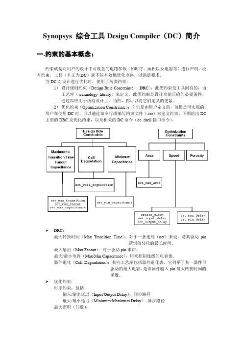
下图给出DC 主要的DRC及优化约束,以及相关的DC命令(dc_shell接口命令)。
DRC:最大转换时间(Max Transition Time):对于一条连线(net)来说,是其驱动pin逻辑值转化的最长时间。
最大扇出(Max Fanout):对于驱动pin来讲。
最大/最小电容(Max/Min Capacitance):用来控制连线的电容值。
器件退化(Cell Degradation):某些工艺库包括器件退化表,它列举了某一器件可驱动的最大电容,是该器件输入pin最大转换时间的函数。
优化约束:时序约束:包括输入/输出延迟(Input/Output Delay):同步路径最大/最小延迟(Minimum/Maximum Delay):异步路径最大面积(门数):最小孔隙度(Min porosity):可布线性二.约束报告约束报告提供了设计规则和优化约束的信息。
可采用如下命令产生相应报告:report_constraintreport_portreport_clockreport_attributereport_timing_requirements用户可通过输出相应报告,来分析设计是否满足了约束。
DC综合过程,Design Compiler

Design Compiler 使用简要说明Design Compiler可以针对层次化的组合电路或者时序电路的速度、面积和可布性进行优化。
按照所定义的电路的测量特征所要达到的目标,Design Compiler综合一个电路并将其放入目标库中,这样可以生成适用于你的计算机辅助设计工程(CAE)工具的原理图或网表。
综合的过程如下图:•读入设计及其子设计。
•设置顶层的设计特性参数•设置实际时序和面积目标参数•执行check_design验证设计,识别并且更正错误•进行Design Compiler优化在db、verilog、vhdl文件夹下设计内容都是一样的,只是形式不一样。
Db文件夹:ALARM_BLOCK.db ALARM_COUNTER.db ALARM_SM.dbALARM_STATE_MACHINE.db COMPARATOR.dbHOURS_FILTER.db MUX.db TIME_BLOCK.dbTIME_COUNTER.dbTIME_STATE_MACHINE.db CONVERTOR.pla CONVERTOR_CKT.db TOP.dbVerilog文件夹:ALARM_BLOCK.v ALARM_COUNTER.v ALARM_SM.vALARM_STATE_MACHINE.v COMPARATOR.vHOURS_FILTER.v MUX.vTIME_BLOCK.vTIME_COUNTER.vTIME_STATE_MACHINE.v CONVERTOR.pla CONVERTOR_CKT.v TOP.vVhdl文件夹:ALARM_BLOCK.vhd ALARM_BLOCK.vhd ALARM_SM.vhdALARM_STATE_MACHINE.vhd COMPARATOR.vhdHOURS_FILTER.vhd MUX.vhd TIME_BLOCK.vhdTIME_COUNTER.vhdTIME_STATE_MACHINE.vhd CONVERTOR.pla CONVERTOR_CKT.vhd TOP.vhd设置path参数将 Synopsys_installroot/arch/syn/bin加到.cshrc文件中。
DC使用全书(Design_Compiler)
DC学习----第一章基本概念作者:未知时间:2010-08-15 15:02:50 来自:网络转载1.1 启动文件启动文件用来指定综合工具所需要的一些初始化信息。
DC使用名为“.synopsys_dc.setup”的启动文件,启动时,DC会以下述顺序搜索并装载相应目录下的启动文件:1)、DC的安装目录;2)、用户的home目录;3)、当前启动目录。
注意:后装载的启动文件中的设置将覆盖先装载的启动文件中的相同设置。
下面是一个DC启动文件的实例,它包含了几乎所有重要的设置,下文将结合该实例解释启动文件中各项设置的具体含义。
例1-1(一个DC启动文件):search_path= search_path + {“.”, synopsys_root + “/dw/sim_ver” }search_path= search_path + { “~/risc32/synthesis/libraries” }target_library={ tcb773stc.db }synthetic_library={dw_foundation.sldb}link_library = { “*”, dw_foundation.sldb, tcb773stc.db }symbol_library = { tcb773s.sdb }synlib_wait_for_design_license = {"DesignWare-Foundation"}alias rt “report_timing”designer= XXXXXcompany= “ASIC Lab, Fudan Univ.”search_path指定了综合工具的搜索路径。
target_library为综合的目标库,它一般是由生产线提供的工艺相关的库。
synthetic_library是综合库,它包含了一些可综合的与工艺无关的IP。
dw_foundation.sldb是Synopsys提供的名为Design Ware的综合库,它包含了基本的算术运算逻辑、控制逻辑、可综合存储器等IP,在综合是调用这些IP有助于提高电路性能和减少综合时间。
DC Design Compiler 综合脚本命令及参考模板
DC Design Compiler 综合脚本命令及参考模板Design Compiler 综合脚本常用命令和模板参照自己的设计,以及自己的工艺信息,适当修改下面的Constraints 和 Run Script 等的脚本,添加一些相关的约束语句,就可以运行了详细的命令请参照DC的官方User Guide等相关资料。
Invoking Design CompilerUnix% design_vision # Interactive GUI, WLM mode Unix%design_vision –topographical # Interactive GUI, Topographical mode Unix% dc_shell-t # Interactive shell, WLM mode Unix% dc_shell-t –topographical # Interactive shell, Topographical mode Unix% dc_shell-t –f RUN.tcl | tee –i my.log # Batch mode.synopsys_dc.setupset search_path “$search_path libs cons unmapped rtl”set synthetic_library dw_foundation.sldbset target_library 65nm.dbset link_library “* $target_library $synthetic_library IP.db”set symbol_library 65nm.sdbdefine_design_lib WORK –path ./workset_svf <my_filename.svf>set_vsdc <my_filename.vsdc>history keep 200set sh_enable_page_mode falseset cache_write .set cache_read $cache_writesuppress_message {LINT-28 LINT-32 LINT-33 UID-401} setalib_library_analysis_path [get_unix_variable HOME] alias h history alias rc “report_constraint -all_violators”TCL Commands and Constructsset PER 2.0 # Define a variable and its value echo $PER # Variable substitution , 2.0set MARG 0.95expr $PER * $MARG # expr: *, /, +, -, >, <, =, <=, >=set pci_ports [get_ports A] # Imbedded command set pci_ports[get_ports “Y??M Z*”] # Wildcardsecho “Effctv P = \ # Soft quotes , 1.9[expr $PERIOD * $MARGIN]”echo {Effctv P = \ # Hard quotes[expr $PERIOD * $MARGIN]} # , Effctv P = [expr $PER * $MARG] # Comment lineset COMMENT in_line; # In-line comment set MY_DESIGNS {B1.v ...B26.v} # foreach loop foreach DESIGN $MY_DESIGNS {read_verilog $DESIGN}for {set i 1} {$i < 27} {incr i} { # for loopread_verilog BLOCK_$i.v}Helpful UNIX-like DC-shell commandspwdcdlshistory!!!7!reportsh <UNIX_command>printenvget_unix_variable ARCHConstraintsreset_designset_max_area 0create_clock -period 2 –name Main_Clk [get_ports Clk1]create_clock –period 2.5 –waveform {2 3.5} [get_ports Clk2]create_clock –period 3.5 –name V_Clk; # VIRTUAL clockset_clock_uncertainty –setup 0.14 [get_clocks *]set_clock_uncertainty –setup 0.21 –from [get_clocks Main_Clk] –to [get_clocks Clk2] set_clock_latency –max 0.6 [get_clocks Main_Clk] set_clock_latency –source –max 0.3 [get_clocks Main_Clk]set_clock_transition 0.08 [get_clocks Main_Clk] set_input_delay -max 0.6-clock Main_Clk [all_inputs] set_input_delay –max 0.3 –clock Clk2 –clock_fall –add_delay [get_ports “B E”]set_input_delay -max 0.5 -clock –network_latency_included V_Clk [get_ports “A C F”]set_output_delay -max 0.8 -clock –source_latency_included Main_Clk [all_outputs]set_output_delay -max 1.1 -clock V_Clk [get_ports “OUT2 OUT7]set_max_capacitance 1.2 [all_inputs]set_load 0.080 [all_outputs]set_load [expr [load_of slow_proc/NAND2_3/A] * 4] [get_ports OUT3] set_load 0.12 [all_inputs]set_input_transition 0.12 [remove_from_collection[all_inputs][get_ports B]]set_driving_cell –lib_cell FD1 –pin Q [get_ports B]set_operating_conditions –max WCCOMset auto_wire_load_selection falseset_wire_load_model –name 1.6MGatesset_wire_load_mode enclosedset_wire_load_model –name 200KGates [get_designs “SUB1 SUB2”] set_wire_load_model –name 3.2MGates [get_ports IN_A]set_port_fanout_number 8 [get_ports IN_A] set_false_path -from[get_clocks Asynch_CLKA] -to [get_clocks Asynch_CLKB]set_multicycle_path –setup 4 –from –from A_reg -throughU_Mult/Out –to B_regset_multicycle_path –hold 3 –from –from A_reg -throughU_Mult/Out –to B_regset_isolate_ports –type inverter [all_outputs]set_ideal_network [get_ports reset* select*] set_ideal_network[get_pins FF_SET_reg/Q] set_ideal_network –no_propagate [get_nets CTRL] set_ideal_latency 1.4 [get_ports reset* select*]set_ideal_transition 0.5 [get_pins FF_SET_reg/Q] set_scan_configuration -style <multiplexed_flip_flop | clocked_scan | lssd | aux_clock_lssd> Checking and Removing Constraints and Directivesreport_clock; report_clock -skewreport_designreport_port –verbosereport_wire_loadreport_path_groupsreport_timing_requirements (–ignored) report_auto_ungroupreport_isolate_ports write_script –output <constraints.tcl>check_timingreset_path –from FF1_regremove_clockremove_clock_transition remove_clock_uncertainty remove_input_delay remove_output_delay remove_driving_cell remove_wire_load_modelSyntax CheckingUnix% dcprocheck constr_file.conPhysical Constraints – Topographical Modeset_aspect_ratioset_utilizationset_placement_areaset_rectilinear_outline set_port_sideset_port_locationset_cell_locationcreate_placement_keepoutMisc. Reports# Generate A library report fileread_db library_file.dblist_libsredirect –file reports/lib.rpt {report_lib <libname>}report_hierarchy [-noleaf]# Arithmetic implementation and# resource-sharing info report_resources# List area for all cells in the design report_cell [get_cells –hier *]Run Scriptread_verilog {A.v B.v TOP.v} orread_vhdl {A.vhd B.vhd TOP.vhd} orread_ddc MY_TOP.ddc oracs_read_hdl MY_TOP oranalyze –format verilog {A.v B.v TOP.v}elaborate MY_TOP –parameters “A_WIDTH=8, B_WIDTH=16”current_design MY_TOPlinkif {[check_design] ==0} {echo “Check Design Error”exit # Exits DC if a check-design error is encountered } # Continue if NO problems encounteredwrite –f ddc –hier –out unmappedd/TOP.ddcredirect –tee –file reports/precompile.rpt {source –echo -verbose TOP.con} redirect –append –tee –file reports/precompile.rpt{check_timing} source <Physical_Constraints_TCL_file> or # Source tcl constraints, if available, orextract_physical_constraints <DEF_file> # Extract and apply from an existing# DEF floorplan filegroup_path -name CLK1 -critical_range <10% of CLK1 Period> –weight 5group_path -name CLK2 -critical_range <10% of CLK2 Period> –weight 2group_path –name INPUTS –from [all_inputs]group_path –name OUTPUTS –to [all_outputs]group_path –name COMBO –from [all_inputs] –to [all_outputs]set_fix_multiple_port_nets –all –buffer_constants********************************************************* * ** Insert Expert, Ultra or ACS compile flow here * * **********************************************************check_designreport_constraint –all_violatorsreport_timing –delay –to –from –through –input_pins –max_paths \–nworst –nets –cap –sig –groupreport_areareport_qorset verilogout_no_tri truechange_names –rule verilog –hierwrite –f verilog –hier –out mapped/TOP.vwrite –f ddc –hier –out mapped/TOP.ddcwrite_sdc TOP.sdcwrite_scan_def –out TOP_scan.defwrite_physical_constraints –output TOP_PhysConstr.tcl exitObject Retrieval and Manipulation (Collection Commands)get_ports, get_pins, get_designsget_cells, get_nets, get_clocksget_nets –of_objects [get_pins FF1_reg/Q] get_libs <lib_name>get_lib_cells <lib_name/cell_names> get_lib_pins<lib_name/cell_name/pin_names> all_inputs, all_outputs, all_clocks,all_registers all_connectedall_fanin, all_fanoutall_ideal_netsset pci_ports [get_ports pci_*]echo $pci_ports # , _sel184query_objects $pci_ports # , {pci_1 pci_2 ...} get_object_name $pci_ports # , pci_1 pci_2 ...sizeof_collection $pci_ports # , 37set pci_ports [add_to_collection $pci_ports \[get_ports CTRL*]]set all_inputs_except_clk [remove_from_collection \[all_inputs] [get_ports CLK]]compare_collectionsindex_collectionsort_collectionforeach_in_collection my_cells [get_cells -hier * \-filter “is_hierarchical == true”] {echo “Instance [get_object_name $cell] is hierarchical”}# Filtering operators: ==, !=, >, <, >=, <=, =~, !~filter_collection [get_cells *] “ref_name =~ AN*”get_cells * -filter “dont_touch == true”get_clocks * -filter “period < 10”# List all cell attributes and redirect output to a fileredirect –file cell_attr \{list_attributes –application –class cell}# Grep the file for cell attributes starting with dont_UNIX% grep dont_ cell_attr | more# List the value of the attribute dont_touchget_attribute <cell_name> dont_touchUltra Compile Flow - Topographical or WLM ModeUltra + DesignWare and DFTC licenses available# In “topo” mode (dc_shell-t –topo) specify Milkyway reference and design libraries create_mw_lib –tech <technology_file> -mw_reference_library <mw_reference_libraries> \<mw_design_library_name>open_mw_lib <mw_design_library_name>set_tlu_plus_files -max_tluplus <max_tluplus_file> -tech2itf_map <mapping_file> set compile_auto_ungroup_delay_num_cells 99999999 set compile_auto_ungroup_count_leaf_cells trueset compile_auto_ungroup_override_wlm trueset_ungroup <top_level_and/or_pipelined_blocks> false# OPTIONAL: Disable unconditional auto-ungrouping# of DesignWare hierarchy (not usually recommended) setcompile_ultra_ungroup_dw false# If design contains pipelined sub-designs and the pipeline registers# are grouped together at the input or output, relax timingset_multicycle_path –setup <#_stages> -from U_Pipeline/R3_reg* –to U_Pipeline/R7_reg*# In “ topo” mode, if the floorplan is available, apply or extract the physical constraintssource <physical_constraints_file> ORextract_physical_constraints <DEF_file># OPTIONAL: Exclude specific cells/design from adaptive retiming (-retime) set_dont_retime <cells_or_designs> true# First compilecompile_ultra –scan –retime –timing|-area# The design hierarchy may have changed due to auto-ungrouping/-uniquifying reset_path -from U_Pipeline/R3_reg* -to U_Pipeline/R7_reg* # OPTIONAL: Maintain registered pipeline outputs if requiredset_dont_touch [get_cells U_Pipeline/R12_reg*] true# Optimize registers if pipeline violates timing; Skip if nopipeline issues: set_optimize_registers true –designMy_Pipeline_Subdesignoptimize_registers –only_attributed_designs# Continue if design is NOT meeting all constraints:# Apply more focus on violating critical paths, as necessarygroup_path –name <group_name> -from <path_start> -to <path_end> \ –critical range <10% of max delay goal> -weight 5# Select appropriate second compile# In “topo” mode in DC v2006.06, or any mode in DC v2007.03 or latercompile_ultra –scan –incremental# In “WLM” mode in DC v2006.06set_ultra_optimization truecompile –boundary –scan –map_effort high –incremental (-area_effort medium|low|none)# In “topo” mode prior to DC v2007.03: Write out updated physical constraintswrite_physical_constraints –output PhysConstr.tclDFT Flow – Expert or UltraDFTC license available# Prior to the first compile set the# scan cell styleset_scan_configuration –style ..# Perform the first test-ready compilecompile –boundary –map high –scan # ORcompile_ultra –timing -scan# Continue before the next compile:# Read in the scan specification filesource scan_spec.tcl# Check for DFT rule violationsdft_drc# Preview the scan chainspreview_dft# Insert and optimize scaninsert_dft****************************************************** * ** Execute additional Ultra/Expert optimization * * techniques, as needed * * *******************************************************# After the final compile check the DFT QoR# and write out the scan DEF filedft_drc –coverage_estimatewrite_scan_def -out <my_design.def>Some Scan Specification Commandsset_scan_state test_readyset_dft_configuration ...set_dft_signal ...set_scan_path ...set_scan_configuration ...create_test_protocolExpert Compile FlowNo Ultra license available; DFTC license available compile –boundary –scan –map_effort high# Continue if NOT meeting constraints# Note: -scan requires DFTC licensecompile –boundary –scan –map_effort high –incremental \(-area_effort medium|low|none)# Continue if NOT meeting constraints:# Increase max-delay priority if OK to postpone DRC fixingset_cost_priority –delay# Note: The design hierarchy may have changed due to auto-# uniquifying# Apply more focus on violating critical paths, as necessarygroup_path –name <group_name> -from <path_start> \-to <path_end> –critical range <10% of max delay goal> -weight 5 # Repartition if design is poorly partitioned group –design<NEW_DESIGN> -cell_name <U_NEW_CELL> \{U2 U7 ...}ungroup –start_level 2 U_NEW_CELLcompile –boundary –scan –map_effort high –incremental \(-area_effort medium|low|none)# Or, can ungroup all hierarchy in lieu of group/ungroup# commands with –ungroup_allcompile –boundary –scan –map_effort high –incremental \(-area_effort medium|low|none) –ungroup_all“Pseudo Ultra” Compile FlowUltra license available; No DesignWare license available set compile_auto_ungroup_delay_num_cells 99999999 setcompile_auto_ungroup_area_num_cells 99999999 setcompile_auto_ungroup_count_leaf_cells trueset compile_auto_ungroup_override_wlm trueset_ungroup <top_level_and/or_pipelined_blocks> false# OPTIONAL: Disable unconditional auto-ungrouping# of DesignWare hierarchy (not usually recommended) set compile_ultra_ungroup_dw false# If design contains pipelined sub-designs and the pipeline registers# are grouped together at the input or output, relax timing set_multicycle_path –setup <#_stages> \-from U_Pipeline/R3_reg* –to U_Pipeline/R7_reg*# Enable Ultra optimizations available for compileset_ultra_optimization –no_auto_dwlib trueset hlo_disable_datapath_optimization trueset compile_slack_driven_buffering truecompile –boundary –scan –map_effort high –auto_ungroup delay|area \ (-area_effort medium|low|none)# Note: The design hierarchy may have changed due to auto- # ungrouping and auto-uniquifyingreset_path -from U_Pipeline/R3_reg* -to U_Pipeline/R7_reg* # OPTIONAL: Maintain registered pipeline outputs if required set_dont_touch [get_cells U_Pipeline/R12_reg*] true # Optimize registers if pipeline violates timing; Skip if no pipeline issues:set_optimize_registers true –design My_Pipeline_Subdesign optimize_registers –only_attributed_designs# Continue if design is NOT meeting all constraints: compile –boundary –scan –map_effort high –incremental \ (-area_effort medium|low|none)# Continue if NOT meeting all constraints:set_cost_priority –delay# Ungroup DesignWare components amid combinational logic ungroup <DesignWare_components># Apply more focus on violating critical paths, as necessary group_path –name <group_name> -from <path_start> -to <path_end> \ –critical range <10% of max delay goal> -weight 5 compile –boundary –scan –map_effort high –incremental \ (-area_effort medium|low|none)。
Design Compiler ,DC,使用方法

课前说明: 在进行下面的演示之前需要大家拷一个文件夹 dc_example , 里面有本 节课需要用到的文件(包括本讲义) 。这个文件夹在 /home/eda236 目录下,大家 把它们拷贝到自己的帐号目录下,以备使用。
拷贝命令:cp –r ../eda236/dc_example
点 OK ,设置完成。 3. 读入 verilog 文件 选择 File---�Read
在打开文件对话框中选中要打开的文件,在这里我们选中 example1.v 文件。
在 Log 框中出现 successfully 字样表明读入文件成功。相应命令:read_file
点击红色箭头所指的按钮可以查看该电路的 symbol 图。
点击 OK ,相应命令:compile
在 Log 框中出现 Optimization Complete 字样表明优化完成,如下图所示。
6. 查看报告 6.1 查看面积报告
选择 Design-----�Report Area
点击 OK ,相应命令:report_area。
报告总面积为 180.223999,单位是平方微米。
4. 设置约束条件 4.1 设置时钟约束 在 symbol 图上选中 clk 端口
选择 Attributes-----�Specify Clock
出来设置时钟约束的对话框,按下图设置,给时钟取名为 clock,周期 20ns,上升沿 0ns , 下降沿 10ns 。
点击 OK ,时钟约束设置完成。相应命令:creat_clock 4.2 设置复位信号约束 在 symblo 图中选中 rst_n 端口(在本例中它是复位端口) ,选择 Attributes-----�Optimization Directives-----�Input Port
Design Compiler Lab Guide自学笔记——快速入门DC
Design Compiler Lab Guide自学笔记——快速入门DCfrom Monchy(蒙奇)在2020年秋招前根据Synopsys的Design Compiler Lab Guide2012自学综合工具Synplify,在此分享第一章章详细的学习笔记,几乎是指南的中文翻译,大量的过程截图对初学者很友好。
虽然只有一章,但是对于掌握DC流程的初学者特别重要,共10个任务,很多的设置一旦出错了就卡那了。
本笔记可以帮你避免走弯路。
Design Compiler Lab Guide2012是Synopsys给出的DC综合官方入门指南,里面包涵源码和实验指导,可以在网上自行下载。
1Setup and Synthesis Flow1学习内容描述本实验中使用的三个DC 设置文件中每个文件的内容。
更新common_setup.tcl 文件完全指定逻辑和物理库以及工艺文件在Design Vision 中探索符号和原理图视图通过地形模式下的基本综合步骤进行设计并生成报告访问SolvNet 以浏览《Design Vision 》用户手册2实验指导任务1检查并修改setup 文件1将1ab1目录作为工作目录并列出以下内容文件:#cd /home/IC/Desktop/DC/lab1#ls -al.synopsys*查看所有前面以”.synopsys”开头的关键字的隐藏文件#ls -al *setup*查看所有只要包含有关键字”setup”的文件.synopsys_dc.setup 文件(.开头为隐藏文件)定义别名,source 另外两个设置文件:common_setup.tcl 和dc_setup.tcl 。
(source 报错,不知道怎么弄)common_setup.tcl 文件包含用户自定义的变量,用于指定工艺文件和目录名。
这些变量在dc_setup.tcl 中使用。
在终端中显示echo 打印的内容dc_setup.tcl文件使用common_setup.tcl中的变量执行命令以加载必要的逻辑和物理工艺数据。
Design Compiler使用笔记_DC中文笔记
DC的手册包括3部分,分别是命令行手册,User Guide,以及参考手册。
其中参考手册有3个,分别是:Constraints & TimingOptimization & Timing AnalysisRegister Retiming本系列笔记为阅读这三个参考手册所做的笔记本文档(约束和时序)包括六章:1. 基本概念2. 约束设计3. 描述设计环境4. 指定时钟和时钟网络5. 描述逻辑功能和信号端口6. 在层次化设计中传播约束Notes for D基本概念篇:利用DC进行综合,主要的过程就是设定适当的约束,从而指导DC综合出较为优化的结果,DC当中进行综合可以分成三大步骤:Transfer、Mapping、Optimization。
总的流程来说为:1.设定各种用于综合的库(.db或者.lib格式)及各种IP核的库。
库中主要描述了库线负载模型、Max_transition、Max_Capacitance 等等;各种单元的时延、面积、逻辑功能、输入输出负载、功耗等等,注意,具有相同footprint的单元是可以互相替换的。
2.读入设计此时可以对设计设定参数(Verilog当中的parameter,VHDL当中的generic)。
设计读入以后将会被转换(Transfer)成网表,该网表是基于一种通用库的,即gtech库(Generic Technology),该库可以较为容易的映射到各种实际的工艺库当中,当然,这个库是没有时延的。
3.设定约束DC的约束总体分成两类:Design Rule Constraints以及Optimization Constraints。
前者是必须要满足的,包括工艺库当中进行的各种限定,而后者是为了优化而设定的。
总的说来,约束包括面积,时序,负载,Porosity,动态/漏功耗(使用Power Compiler )等几大类。
4.约束设定好之后,就可以让DC根据这些约束将通用库的网表映射(Mapping)到实际的库当中去,并进行各种的优化(Optimization),此时就可以得到结果的网表,用于后端的布局布线。
Design Compile (DC) 使用说明
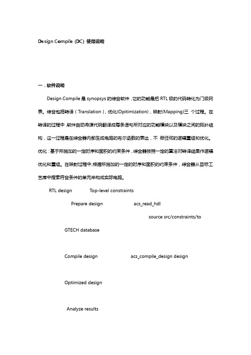
Design Compile (DC) 使用说明一.软件说明Design Compile是synopsys的综合软件,它的功能是把RTL级的代码转化为门级网表。
综合包括转译(Translation),优化(Opitimization),映射(Mapping)三个过程。
在转译的过程中,软件自动将源代码翻译成每条语句所对应的功能模块以及模块之间的拓扑结构,这一过程是在综合器内部生成电路的布尔函数的表达,不做任何的逻辑重组和优化。
优化:基于所施加的一定时序和面积的约束条件,综合器按照一定的算法对转译结果作逻辑优化和重组。
在映射过程中,根据所施加的一定的时序和面积的约束条件,综合器从目标工艺库中搜索符合条件的单元来构成实际电路。
RTL design Top-level constraintsPrepare design acs_read_hdlsource src/constraints/to GTECH databaseCompile design acs_compile_design designOptimized designAnalyze resultsConstraints met ? DoneNoRefine design acs_refine_design designRefined designDC有两种界面,图形界面通过敲入design vision&调用出来,另一种命令行界面通过dc_shell-t调用。
建议初学者使用图形界面,因为图形界面比较容易上手;业界的人士比较青睐命令行界面,因为其所耗的资源少,并且将所用的命令写成综合脚本的形式,便于查阅。
因为门级和代码级不同,代码级考虑的是理想情况,但是实际电路不是这样的,它有门级的延时,线的延时,信号的转换时间,甚至时钟信号到达各个触发器的时间不相等。
基于这些考虑,DC通过施加约束,模拟实际环境,根据实际情况得出门级网表。
因此如何适当的施加约束是DC的关键所在。
DC逻辑综合使用流程
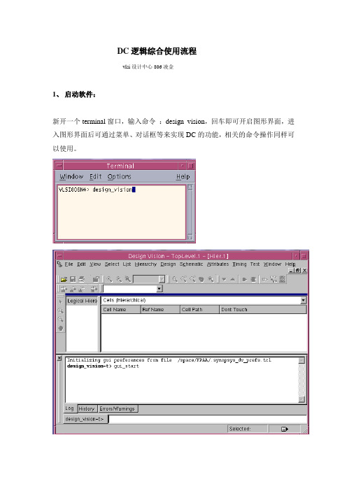
DC逻辑综合使用流程vlsi设计中心806凌金1、启动软件:新开一个terminal窗口,输入命令:design_vision,回车即可开启图形界面,进入图形界面后可通过菜单、对话框等来实现DC的功能,相关的命令操作同样可以使用。
2、指定相关库文件及路径“File > Setup”打开下图所示对话框Search_path指定了搜索路径,点击右侧按钮进入如图所示对话框点击add添加库文件所在路径。
Target_library为逻辑综合的目标库,由代工厂提供的* .db 文件,用相似的方法添加所需库文件。
Link_library是链接库,一般和目标库相同注:“*”这一项要保留,否则链接时会出错,该项指示DC在链接时首先搜索内存中的内容。
Symble_library为指定的符号库,一般为*.sdb 文件,与单元的库文件对应。
3、设计读入“File > Read”读入设计文件,用此方式读入时在此处不用指定顶层文件,但读入后应马上指明设计的顶层名。
通过左侧的窗口可以观察设计的层次4、链接“File > Link Design”在弹出对话框中点击“ok”即可完成链接。
其执行的相关信息可从命令框中可查看5、实例唯一化当设计中有某个子模块被多次调用时就需要进行实例唯一化,实例唯一化就是将同一个子模块的多个实例生成为多个不同的子设计的过程。
之所以要进行实例唯一化是因为DC在逻辑综合时可能使用不同的电路形式来实现同一个子模块的不同实例,从而这些实例在DC看来是不同的设计(尽管其调用的子模块代码和功能完全相同)。
实现方法:“Hierarchy > Uniquify > Hierarchy ”在弹出对话框中默认点击“ok”即可,命令框中将显示“design_vision-t> uniquify”。
若选中“instances to be renamed even if unique or assigned don’t_touch”则会强制将所调用的模块从新命名,此时命令框中显示“design_vision-t> uniquify –force”。
SynopsysDC中文培训实验

SYNOPSYSLab1Setup and Synthesis Flow缩略词:Design Compile =DC;备注:UNIX%代表在linux终端下进行操作,其余的代表在DC下进行DC命令输入前言:DC(Design Compiler)是Synopsys的logical synthesis优化工具,它根据design description 和constraints自动综合出一个优化了的门级电路。
它可以接受多种输入格式,如硬件描述语言、原理图和netlist等,并产生多种性能报告,在缩短设计时间的同时提高读者设计性能。
基本的综合流程:该基本综合流程包含下列步骤:1. 发展HDL文件输入Design Compiler的设计文件通常都是用诸如VHDL和Verilog HDL等硬件描述语言编写。
这些设计描述必须小心地编写以获得可能的最好的综合结果。
在编写HDL代码时,你需要考虑设计数据的管理、设计划分和HDL编码风格。
划分和编码风格直接影响综合和优化过程。
虽然流程中包含该步骤,但实际上它并不是Design Compiler的一个步骤。
你不能用Design Compiler工具来编写HDL文件。
2. 指定库通过link_,target_,symbol_,和synthetic_library命令为Design Compiler指定链接库、对象库、符合库和综合库。
链接库和对象库是工艺库,详细说明了半导体厂家提供的单元和相关信息,象单元名称、单元管脚名称、管脚负载、延迟、设计规则和操作环境等。
符号库定义了设计电路图所调用的符号。
如果你想应用Design Analyzer图形用户界面,就需要这个库。
另外,你必须通过synthetic_library命令来指定任何一种特殊的有许可的设计工具库(你不需要指定标准设计工具库)。
3. 读入设计Design Compiler使用HDL Compiler将RTL级设计和门级网表作为设计输入文件读入。
dc综合约束指令 -回复
dc综合约束指令-回复什么是DC综合约束指令?DC综合约束指令(Design Compiler Constraints,简称DC综合约束)是一种用于面向集成电路设计的约束语言。
它在针对ASIC(Application Specific Integrated Circuit,特定应用集成电路)和FPGA(Field Programmable Gate Array,现场可编程门阵列)的综合过程中起到关键作用,通过指令来约束设计的行为,以达到预期的功能和性能要求。
DC 综合约束指令可以对设计的时序、电气特性、布局约束等多个方面进行详细的控制和配置。
本文将详细介绍DC综合约束指令的使用方法和基本原理。
1. DC综合约束指令的作用DC综合约束指令的主要目的是确保综合工具(如Synopsys Design Compiler)在进行逻辑综合时,可以根据设计者的设定和需求生成所期望的结果。
通过约束指令,我们可以对时序约束、电气特性和布局进行定制,使得综合工具在生成门级电路前能够尽可能满足设计的目标和要求。
2. 时序约束时序约束是DC综合约束指令中非常重要的一部分。
它用来确保产生的电路能够在时钟和数据之间正确地进行数据传输,以满足设计要求。
时序约束通常包括时钟频率、时钟占空比、输入输出延迟、最大工作频率等参数。
设计者需要根据目标器件和设计要求,精确地设置这些参数,以避免时序违例和数据错误。
通过时序约束,我们可以控制电路的时钟域和数据路径,从而保证电路的正确性和稳定性。
3. 电气特性约束DC综合约束指令还可以用于设定电气特性约束,以确保集成电路的电气性能符合预期。
这些特性包括功耗、噪声容限、信号完整性等。
通过设置电气特性约束,设计者可以控制电路的功耗消耗、电压稳定性以及信号传输的准确性。
这些约束对于不同的应用场景和器件有着不同的要求,设计者需要根据实际情况进行合理的设定和优化。
4. 布局约束DC综合约束指令还可以用于对电路的布局进行约束。
DC实验报告流程
实验一DC(design compile)的基本使用流程Design Compiler是Synopsys综合软件的核心产品。
它提供约束驱动时序最优化,并支持众多的设计类型,把设计者的HDL描述综合成与工艺相关的门级设计;它能够从速度、面积和功耗等方面来优化组合电路和时序电路设计,并支持平直或层次化设计。
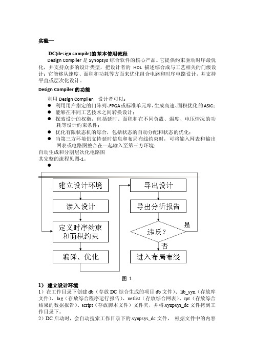
Design Compiler的功能利用Design Compiler,设计者可以:●利用用户指定的门阵列、FPGA或标准单元库,生成高速、面积优化的ASIC;●能够在不同工艺技术之间转换设计;●探索设计的权衡,包括延时、面积和在不同负载、温度、电压情况的功耗等设计约束条件;●优化有限状态机的综合,包括状态的自动分配和状态的优化;●当第三方环境仍支持延时信息和布局布线约束时,可将输入网表和输出网表或电路图整合在一起输入至第三方环境;自动生成和分割层次化电路图其完整的流程见图-1。
●图 11)建立设计环境1)在工作目录下创建db(存放DC综合生成的项目db文件)、lib_syn(存放库文件)、log(存放综合程序运行报告)、netlist(存放综合网表)、rpt(存放综合结果的数据报告)、script(存放脚本文件)文件夹,并将.synpsys_dc文件拷到工作目录下。
2)DC启动时,会自动搜索工作目录下的.synpsys_dc文件,根据文件中的内容来设定综合环境。
因此,在启动DC前,可以先修改.synpsys_dc中库文件的路径(也可以在进入DC后设置)。
set search_path "$search_path ../ref/db ./scripts" ……指明库所在的路径set target_library "sc_max.db"……目标库set link_library "* sc_max.db"……链接库set symbol_library "sc.sdb" ……特征库在上述环境建立所需的各类库中,一般由生产商提供目标库,库中的各类cell用于逻辑映射,链接库则包括一些已经做好的设计和子模块,还包括了当前设计的目标库,门级网表实例化元件和单元都来自于它。
- 1、下载文档前请自行甄别文档内容的完整性,平台不提供额外的编辑、内容补充、找答案等附加服务。
- 2、"仅部分预览"的文档,不可在线预览部分如存在完整性等问题,可反馈申请退款(可完整预览的文档不适用该条件!)。
- 3、如文档侵犯您的权益,请联系客服反馈,我们会尽快为您处理(人工客服工作时间:9:00-18:30)。
DC使用说明文件说明:在进行下面的演示时需要用到两个文件,一个是example1.v,它是描述一个电路的verilog代码,我们的目标就是用DC综合这个代码得到满足约束条件的电路网表;另一个是dc.scr,它是综合example1.v的脚本文件。
这两个文件都在/home/stu100目录下,大家把它们拷贝到自己的目录下,以备使用。
DC既可使用图形界面,也可不使用图形界面而直接运行脚本来综合电路。
一、DC图形界面的使用。
1.DC图形界面的启动1.1 打开一个终端窗口,写入命令dv –db_mode,敲入回车。
则DC图形界面启动,如下图所示红框处是DC的命令输入框,以下在图形界面上的操作都可以在命令输入框中输入相应的命令来完成。
选择Help----- Man Pages可以查看DC的联机帮助。
相应指令:man。
例:man man表示查看man命令的帮助。
man create_clock表示查看creat_clock命令的帮助。
2.设置库文件选择File---- Setup需要设置以下库文件,如下图。
相应指令:set search_path [list /tools/lib/smic25/feview_s/version1/STD/Synopsys \/tools/lib/smic25/feview_s/version1/STD/Symbol/synopsys] set target_library { smic25_tt.db }set link_library { smic25_tt.db }set symbol_library { smic25.sdb }点OK,设置完成。
3.读入verilog文件选择File--- Read在打开文件对话框中选中要打开的文件,在这里我们选中example1.v文件。
在Log框中出现successfully字样表明读入文件成功。
相应命令:read_file点击红色箭头所指的按钮可以查看该电路的symbol图。
4.设置约束条件设置时钟约束在symbol图上选中clk端口选择Attributes----- Specify Clock出来设置时钟约束的对话框,按下图设置,给时钟取名为clock,周期20ns,上升沿0ns,下降沿10ns。
点击OK,时钟约束设置完成。
相应命令:creat_clock设置复位信号约束在symblo图中选中rst_n端口(在本例中它是复位端口),选择Attributes-----→Optimization Directives-----→Input Port勾选Don’t touch network选项,点击OK。
相应命令:set_dont_touch_network4.3 设置输入信号延迟约束同时选中输入端口a,b,c选择Attributes----→Operating Environment-----→Input Delay设置Relative to clock为clock(即我们刚才加约束的时钟信号),并设置上升延迟为8ns(根据经验,该值是时钟周期的40%,本例中设置了时钟周期为20ns,20*0.4=8ns)相应命令:set_input_delay在symblo图上选中输出端口o。
选择Attributes-----→Operating Environment-----→Output Delay相应指令:set_output_delay4.5设置面积约束选择Attributes-----→Optimization Constraints-----→Design Constraints设置Max area的值为0,表明让DC向电路面积为0的方向来优化电路,使面积最小。
当然,面积为0是达不到的。
Max fanout为4,Max transition为0.5(具体含义参见SYNTHESIS.pdf)相应命令:set_max_area,set_max_fanout,set_max_transition。
5.综合优化选择Design----- Compile Design点击OK,相应命令:compile在Log框中出现Optimization Complete字样表明优化完成,如下图所示。
6.查看报告查看面积报告选择Design----- Report Area点击OK,相应命令:report_area。
报告总面积为180.223999,单位是平方微米。
查看约束报告选择Design----- Report Constraints在这里我们只查看all violators选项(勾选show all violators),该选项是报告综合后所有不满足原先设置的约束条件的条款。
从下图可以看出只有max_area(最大面积)约束不满足,因为我们设置的最大面积约束是0(见 4.5),而实际综合出的电路面积是180.22。
该项violator是合理的。
如果还存在其它violators,说明前面的约束设置不合理或电路设计不合理,需要对其修改,最终要求除max_area violator外没有其它violators。
相应命令:report_constraint时序报告选择Timing----- Report Timing报告的是最大延迟路径。
相应命令:report_timing选择File----- Save As保存成.db文件保存成.v文件(即网表文件)相应命令:write8.退出DC选择File----- Exit。
相应命令:exit。
二、DC脚本的使用脚本是许多命令的集合,在运行脚本时,DC按脚本里的命令顺序执行。
1.启动非图形界面打开一个终端窗口,输入dc_shell-t,回车。
出现红框里字样表明启动DC成功。
2.运行脚本输入source ./dc.scrOptimization complete表明综合优化完成。
3.退出DC输入exit命令退出。
dc.scr脚本内容说明dc.scr脚本的内容如下:(蓝色字体是说明,脚本中并没有这些文字)sh date //显示开始时间remove_design –designs //移除DC中原有的设计//下面是库的设置,对应图形界面操作的2###########################set library ###########################set search_path [list /tools/lib/smic25/feview_s/version1/STD/Synopsys \/tools/lib/smic25/feview_s/version1/STD/Symbol/synopsys]set target_library { smic25_tt.db }set link_library { smic25_tt.db }set symbol_library { smic25.sdb }//下面是屏蔽一些warning信息,DC在综合时遇到这些warning时就把它们忽略,不会报告这些信息,VER-130,VER-129等是不同warning信息的编码,具体含义可以查看帮助###########################void warning Info ###########################suppress_message VER-130suppress_message VER-129suppress_message VER-318suppress_message ELAB-311suppress_message VER-936//读入example1.v文件,对应于图形界面的3#################################read&link&Check design#################################read_file -format verilog ~/example1.vcurrent_design EXAMPLE1 //把EXAMPLE1指定为当前设计的顶层模块//设置一些变量############################## define IO port name ##############################set clk [get_ports clk] //设置变量clk的值是[get_ports clk],在下面的代码中若出现$clk字样,则表示引用该变量的值,即用[get_ports clk]代替$clk。
set rst_n [get_ports rst_n]set general_inputs [list a b c]set outputs [get_ports o]//设置约束条件,对应于图形界面的4############################## set_constraints ##############################//设置时钟约束,对应于图形界面的4.1#1 set constraints for clock signalscreate_clock -n clock $clk -period 20 -waveform {0 10} //创建一个周期为20ns,占空比为1的时钟set_dont_touch_network [get_clocks clock]set_drive 0 $clk //设置时钟端口的驱动为无穷大set_ideal_network [get_ports clk] //设置时钟端为理想网线//设置复位信号约束,对应于图形界面的4.2#2 set constraints for reset signalsset_dont_touch_network $rst_nset_drive 0 $rst_nset_ideal_network [get_ports rst_n]//设置输入延时,对应图形界面的4.3#3 set input delayset_input_delay -clock clock 8 $general_inputs//设置输出延时,对应图形界面的4.4#4 set output delayset_output_delay -clock clock 8 $outputs//设置面积约束和设计约束,对应图形界面的4.5#5 set design rule constraintsset_max_fanout 4 $general_inputsset_max_transition 0.5 [get_designs "EXAMPLE1"]#6 set area constraintset_max_area 0//综合优化,对应图形界面的5############################## compile_design ##############################compile -map_effort medium//保存文件,对应图形界面的7########################### write *.db and *.v ###########################write -f db -hier -output ~/EXAMPLE1.db EXAMPLE1 -xg_force_dbwrite -f verilog -hier -output ~/EXAMPLE1netlist.v EXAMPLE1write_sdf -version 1.0 ~/EXAMPLE1.sdf //保存反标文件($sdf_annotate("../syn/sdf/CFHC_TOP.sdf");)//产生报告并保存,对应图形界面的6########################### generate reports ############################1report_area > EXAMPLE1.area_rpt //把报告面积的文件保存成EXAMPLE1.area_rpt文件,运行完脚本以后可以查看该文件。
