TOHNICHI LC200N说明书
伦次变频器说明书

伦茨(Lenze)变频器8200Vector系列使用说明注:本说明适用于梳棉机FA231A所使用 Lenze E82EV系列变频器包括内容:1.标准接线及安装400V控制器的主电源接线电机接线符合EMC标准的安装控制端子接线及说明2. 用操作面板进行参数设定访问,设定所有参数拷贝参数到操作面板从操作面板复制参数到变频器输出转速的在线调整--用操作面板输入频率(hz)与其他给定值相加3.重要参数代码说明C0014代码可设置控制模式电机数据的输入/自动检测(C0087;C0088;C0089;C0090;C0091;C0084;C0092;C0148)JOG固定频率给定值(C0037,C0038,C0039)给定值选择(C0001)模拟输入给定的调整(C0026;C0027)PTC电机温度监控(C0119)数字输入信号配置(C0007)最小输出频率(C0010)最大输出频率(C0011)主加速时间(C0012)主减速时间(C0013)快停减速时间(C0105)数字输入信号E1-E6电平反相(C0114)模拟量输入范围设定(C0034)电流极限设定(C0022,C0023)4.故障诊断及排除运行状态显示故障查询5. 梳棉机FA231A变频器参数设定表E82EV222S4B参数设定表E82EV751S4B参数设定表6.变频器调试程序表7.产品维护,保养要点1.标准接线及安装400V控制器的主电源接线电机接线见上图注:BR1,BR2外部制动电阻T1,T2电机温度监控PTC热敏电阻或热继电器符合EMC标准的安装注:将控制线及电源线与电机电缆分开使用低寄生电容电缆。
每单位长度电容值:●芯/芯≤75pF/m●芯/屏蔽层≤150pF/mEMC电缆密封垫按铭牌进行电机接线使用表面导电的安装板以尽可能大的导电表面将电缆屏蔽层连到PE上。
使用Lenze提供的固定支架。
控制端子接线及说明注:●插上端子排前,先接好线!●仅可在控制器禁止时插拔端子排!●不用的端子排也应插上,以保护连接部件。
欧特顿自动转换开关产品介绍说明书

Unmatched performance forcritical power needsEaton’s automatic transfer switch is designed to provide unmatchedperformance, reliability and versatility for critical standby powerapplications. The switches can be equipped with the ATC-300+ orATC-900 controllers to match your application needs. A bypass isolationtransfer switch may be used to provide emergency power to life safetyand other critical loads where maintenance of the main transfer switch,without interruption of power to the load, is either desirable or required.Electrical ratings• Operating temperature–20° to +70°C (–4° to +158°F)• Ratings 100, 150, 200, 225, 260, 400, 600, 800, 1000, 1200 and 1600A• Two-, three- or four-pole (fourth pole is fully rated)• Up to 600 Vac, 50/60 Hz• NEMA® 1, 3R, 12, 4X• UL® 1008 Listed• CSAா C22.2 No. 178 Certified Industrial design highlights• Standard front accesson all ratings• Entry:• Top, bottom or both• Isolated compartments• Field-selectable multi-taptransformer panel permitsoperation on a wide rangeof system voltages• Improved safety:• Isolated compartmentswith barriers• Single motion rack-outwith doors closed• Ability to test power-switching elementsduring drawout process• Dual ATS capability—bypasscontactor can be controlledby the ATS controller in thebypass mode of operation• Installation flexibility:• Field entry/exit locationscan be modified in the field• Interchangeable drawoutcontactorsStandard features• Source available contacts• S1/S2 present 2NO and 2NC• Switch position contacts• S1/S2 position 1NO and 1NC• Source sensing S1 and S2• Undervoltage/underfrequency• Overvoltage/overfrequency• Three-phase rotationprotection• Three-phase voltageunbalance• Pretransfer signal contacts1NO/1NC• Go to Source 2 (emergency)• Field-programmable timedelays• Time delay engine start• Time delay normalto emergency• Time delay emergencyto normal• Time delay enginecool-down• Time delay emergency fail• LCD display for programming,system diagnostics and Helpmenu display• Mimic diagram with sourceavailable, connected, andstatus LED indication• Time-stamped history log• System TEST pushbutton• Programmable plantexerciser—off, daily, 7, 14,28-day, selectable runtime,0–600 minutes no load / loadwith fail safeOptional features•Available surge protectiondevice (SPD)•Eaton IQ and Power Xpertாmultifunction power qualitymetering•Automatic transfer mode withselectable non-automatic/automatic retransfer mode• Modbusா RTU via RS-485• Remote annunciationwith control• Open in-phase transition,time delay neutral or in-phasewith a default to time delayneutral transfer• ATC-900 Controller• Includes Modbus RTUvia RS-485• Includes four programmableinputs/outputs• Includes two plantexercisersDrawout Bypass Isolation•Includes LCD color displaywith easy navigation toolsto settings and event logs•Expandable I/O (up to20 I/O total)•Optional integrated loadmetering•Optional EtherNet TCP/IPcommunicationsBypass isolationswitch featuresFront accessFront access is a standard fea-ture. Source 1 (NORMAL) and Load connections are set up as standard top entry and Source 2 (EMERGENCY) connections as bottom entry. These connections are located in their own separate compartments. These connections can be relocated in the field if necessary.Multi-tap transformerThe industry-exclusive multi- tap system voltage selector allows the transfer switch to be applied on most system voltages by proper insertionof the selector plug. Dual drawout ATS andbypass contactorThe ATS and the bypass drawoutpower contactor designs areidentical and interchangeable.This standard feature allowsthe user the ability to withdraw,maintain or swap contactorassemblies, providingredundancy of ATS and bypassfunctions from one contactorassembly to the other of asimilar frame size.Improved safetyThe unique Eaton designincludes separation betweencontrol and power components.The ATS and bypass isolationcontactors are mounted inseparate compartments withprotective barriers betweenthem. This design preventsthe possibility of contactwith the rear-mounted powerconnections to the contactors.In addition, the top andbottom entries have separatecompartment doors.Ease of maintenanceTransfer to the bypass powercontactor is easily initiated andcontrolled via door-mountedcontrols. After the transferto the bypass contactor iscomplete, the ATS contactoris easily racked out with thecompartment door closed.The ATS contactor may then betested in the racked-out position.Ease of transferThe Eaton design allows theoperator to make a quick andsimple transfer from the ATSpower contactor to the bypasscontactor by initiating theelectrically operated transfervia a two-position switch.Door-mounted indicating lightsconfirm that a successfultransfer has taken place.Dual ATS capabilityThe controller on conventionalbypass isolation switches onlycontrols the ATS contactor. TheEaton design allows the switchcontroller to remain active inboth the ATS and the bypassmodes, thus providing controlto either contactor.This ability of the controller toremain active and control thebypass isolation contactorprovides ”N+1” redundancyof a second fully functioningATS, a feature unique to Eaton.Drawout ATSSeparate ATSCompartmentDrawout Bypasswith SeparateCompartmentDoor—ShownSeparate Doors forATS and BypassCompartmentsDrawout BypassContactorDrawout ATS2EATON Automatic transfer switchesA For seismic applications, it is necessary to use 513 UNC Grade or better hex head bolts and washers torqued to 50 lbs-ft.B NEMA 12 and 4X dimensions are 90.00 inches H x 46.00 inches W x 38.00 inches D (2286.0 mm H x 1168.4 mm W x 965.2 mm D). NEMA 4X enclosures are 304SS standard with an optional upgrade to 316SS.C Same number of terminals per phase will be supplied.D For NEMA 3R dimensions, add 18.29 inches (464.6 mm).E For NEMA 3R dimensions, add 18.59 inches (472.2 mm).3EATON Automatic transfer switchesAutomatic Bypass Isolation Contactor-Based T ransfer Switch Catalog Numbering Systemotee:N 1600A is rated for 480V and below.4EATON Automatic transfer switchesEaton is a registered trademark.All other trademarks are property of their respective owners.Eaton5050 Mainway Burlington, Ontario L7L 5Z1 CanadaEatonCanada.ca© 2020 EatonAll Rights Reserved Printed in CanadaPublication No. PA01602013E October 2021UL 1008Withstand and Close-On Ratings (kA)1 Time duration is 0.13 sec. maximum.。
东崎电气接近开关使用说明书

接近开关使用说明书感谢您对广东东崎电气有限公司产品的信赖,当您使用我公司产品时请务必参阅本说明,以免因操作失误而造成不必要的损失。
例:TKI-12N4C表示直插式插头连接型,直流电感式接近开关,外形为M12圆柱型,NPN常开,动作距离为4mm,最大输出电流为200mA.二、距离的设定※开关的动作距离请设定在80%检测距离(Sn)内,以免开关工作受温度、电压等影响。
※当检测其它金属时,开关有不同的动作距离。
(图1)※当开关用作测量动作频率或其它高速场合,请将开关的动作距离设定在1/2检测距离(Sn),开关在此位置可获得最大的动作频率。
※电容式接近开关的动作距离设定,请参阅电容式接近开关的使用说明。
(见五)不锈钢铬镍铜铝二、接线图PNP(直流型)三、串联及并联NPN(直流型)直流二线型检测距离交流二线型(图1)电源电源交流串联交流并联若电源电压为220V,且串联数在3个以内,可使用上图的接法,否则请按下图方法通过继电器进行串联。
并联的开关A和B,若检测体接近开关A,开关A动作,负载电流流过开关A,开关A(B)两端电压降为10V,若此时检测体再接近开关B,因开关两端的电压为10V,开关B会因电压不足而不动作,只有当关闭开关A,使A(B)两端的电压升高至使用电压,开关B才动作,开关A关闭与开关B动作的时间间隔约为10mS,因而当需要多个接近开关并联时应注意开关相互之间的影响,一般请按下图通过继电器进行并联。
电源AC 电源※直流电源必须使用绝缘变压器,请勿使用自耦变压器;※电力线、动力线通过开关引线附近时,为防止开关误动作和损坏,请使用金属配管线。
四、注意事项※交流型开关,若电源电压为110V时,串联必须经过继电器使用;※交流型开关必须经过负载接电源,若直接将开关接电源会损坏开关。
电源AC 电源×错误接法√正确接法※接近开关的引线长度请在200米以下,以免电压降过大。
五、电容式接近开关的使用说明※电容式接近开关不仅能检测金属,而且能检测塑料、玻璃、水、油等物质,因各种检测体的导电率和介电常数、吸水率、体积的不同 故相应检测距离也不同,对于接地的金属可获得最大的检测距离。
LC200称重仪表最新版说明书共31页
概述LC200系列仪表被设计用于诸如皮带秤、配料秤、定量秤、料斗秤、减重秤、失重秤等连续累计自动衡器的称重显示控制器,并严格按照Q/140000LC001-2019《LC200称重显示控制器》企业标准研制开发。
LC200系列仪表具有多种可选择的通讯联网接口和可扩展的控制接口,可以满足用户多种计量、检测、控制和联网的需求,全中文图形显示方式提供了丰富的运行数据和简洁的操作界面,并具有盘装、台式、壁挂三种结构方式,用户可根据安装环境和使用方式选用相应的机型。
本说明书提供LC200系列仪表的选型、安装、调试、操作和维护的方法。
LC200系列仪表操作虽然简单,但错误的安装和误操作可能引起计量精度的下降、控制功能的丧失、外部配套设备的损坏以及意外事故的发生。
因此在安装和使用前务必仔细阅读本使用说明书,直至掌握正确的安装和使用方法。
LC200系列仪表的功能和型号将在以后不断增加,我们力求做到每次再版使用说明书时,其内容与当时的LC200系列仪表一致,但可能出现遗漏或错误,因此希望您给予谅解。
特别是当您发现错误、疑点或遗漏之处时,请及时咨询我们或经销商以获得最新信息。
仪表交货时的注意事项用户拆开LC200仪表的包装箱时,请认真确认:■在运输过程中是否有损坏■仪表铭牌数据是否与订货一致■随仪表一起发送的附件是否齐全■通电检查仪表显示功能和按键操作是否正常。
本公司严格按照ISO9000质量体系进行开发和制造,每台产品出厂前都经过严格的质量检测,如果发现有缺陷,请速与厂家或经销商联系解决。
产品的保修用户购买本产品起一年内为产品保修期,在以下情况,即使在保修期内,也是有偿服务:■错误的安装使用及不适当的修理、改造引起的故障■超过仪表技术指标规定的范围使用而出现的故障■购买后人为损坏或不可抗自然因素损坏。
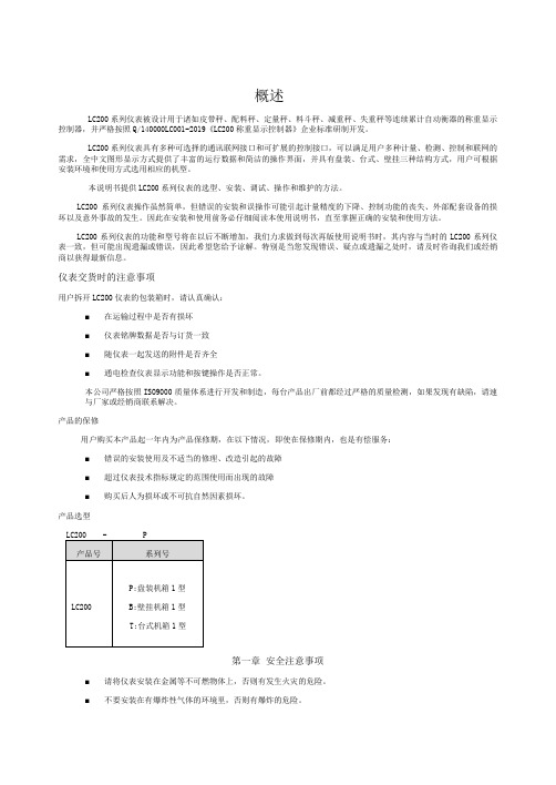
产品选型第一章安全注意事项■请将仪表安装在金属等不可燃物体上,否则有发生火灾的危险。
■不要安装在有爆炸性气体的环境里,否则有爆炸的危险。
胜利仪器 VICTOR 7200漏电保护器测试仪 说明书

4
电保护器还是不跳闸,再过 2 秒钟后继续加大一档额定动作电流测试,直到跳闸分 断为止,此时仪表 LCD 下方所指示的电流档位就是漏电保护器的实际漏电动作电流 值,显示的时间就是其漏电动作时间值。 3.额定动作电流档位切换
确保仪器按照指定要求与被测线路连接完成后,在 AT 模式下按下“RESET” 键启动测试等待跳闸完成,测试从最低档 15mA 开始依次增加,等待直到跳闸为止。 在 MT 模式下通过手动选择对应的档位,连接好线路后按下“RESET”键启动测试 等待跳闸完成。 5.测试
有电,危险!必须由经培训并取得授权资格的人员操作,操作者必须严格 遵守安全规则,否则有电击的危险,造成人身伤害或设备损坏。 不能用于测试超过 250V 电压的线路。否则有电击危险,造成人身伤害或 设备损坏。 仪表的 L 接口需连接被测试漏电保护器的火线端,仪表的 N 接口需连接被 测试漏电保护器的接地端,否则有电击危险,可能造成设备损坏。 仪表配置的插座测试线是专用定制的,红色插头接火线,黑色插头接地线, 严禁使用其他插头线代替使用,否则有电击的危险,造成人身伤害或设备 损坏。 测试前需先拆开被测漏电保护器的负载引线,避免损坏负载端设备。再查看被 测试漏电保护器的铭牌标定值,根据铭牌标定值确定漏电电流档位。(一般户内型单
二.电气符号......................................................................................................................... 2 三.技术规格......................................................................................................................... 2 四.仪表结构......................................................................................................................... 4
康诚机组产品使用说明书
第一章安全手则操作发电机之前,需先阅读操作手册,并且熟悉你的设备,只有正确地操作并且维护设备,才能够达到安全、有效的运转。
许多意外伤害产生是由于没有遵循基本规则和安全守则。
燃油和油气非常容易起火●燃油管路必需有足够的安全保证,而且不会渗漏。
和发动机连接处必须用合格而防震的管路,此管路不可使用铜管;●确定所有燃油进油管路皆有控制阀;●检修蓄电池时不可吸烟,铅酸蓄电池会产生爆炸性的氢气,如果有电弧或吸烟的火花会立即发生爆炸。
发动机的排气有致命性●确保机组的通风系统顺畅;●提供一个适当的排烟系统来排放废气,经常目视或耳听检查排气系统是否泄露,并依照保养时间表,确定排气管固定安装好。
转动的机件会使人员重伤或死亡●在起动前的检查保养时,应断开蓄电池线,以防意外起动;●起动之前,应确保零部件的安全,检查其是否紧固牢靠,支架、管夹是否定位,风扇、传动皮带等转动件的护罩是否护好;电击可以使人员受伤或死亡●在维护和保养机组时,应关闭电力电源;在电气设备周围的金属或钢筋结构的地板上,应放置干燥的木版并垫上橡胶绝缘垫;●不允许穿潮湿的衣服和鞋子或皮肤潮湿时处理电气故障;●电压超过36V时,会造成人员伤亡或死亡。
不要擅自修改电气线路;●开关断开时,必须贴上明显标识,防止其他人员误操作,导致人员或设备发生事故;●发电机组不能直接连接到市电供电系统上,否则会造成设备和电力系统损坏或烧损。
安全预防:●在受压的情况下,发动机冷却液的沸点要比一般普通水高,在发动机运转时,千万不要打开水箱或热交换器的压力盖。
检修发动机时,如果需要打开压力盖,必须先让发动机冷却,使压力释放出来后,再打开压力盖;●柴油机内含有导致癌症及其其他有害物质,当检查机组加油或泄油时,不要吸入柴油;●润滑油内含有导致癌症及其其他有害物质,当检查机组加油或泄油时,不要吸入润滑油;●发动机附近不要放置纸屑、布条等等,防止杂物引起火灾;●发电机组上不要放置所有不必要的油脂和润滑油;●发动机排放的废气会导致癌症或其他上海,不要吸入废气,或将废气排入室内;●发电机组和机房应保持清洁,不应放置杂物。
冬日C2R20说明书

数据无线传输扭力扳手型号FHD操作手册Tohnichi Mfg. Co., Ltd.Tokyo, Japan目录1.规格 (2)2.CSPFHD信号发送器视图和各部件名称 (3)3.R-FHD接收器视图和各部件名称 (4)3-1.RS232C接口 (5)3-2.I/O连接端口 (5)3-3.I/O连接端口使用注意事项 (6)4.使用方法 (8)4-1.操作 (8)4-2.工作时序图 (11)4-3.更换电池 (16)4-4.2节AAA可充电镍氢电池 (16)4-5.故障对应 (17)5.RS232C输入/输出规格 (18)5-1.连接协议 (18)5-2.RS232C输入/输出通信格式 (18)5-3.RS232C输入/输出参数设定格式 (22)6.CSPFHD参数设定(通过按键操作) (23)6-1.通道组别、识别码、ID、自动关机时间 (23)6-2.零位设定、扭矩值设定、增益设定 (25)7.CSPFHD参数设定(通过软件设定FHD参数) (27)7-1.通道组别、识别码、ID、自动关机时间 (27)7-2.零位设定、扭矩值设定、线性设定 (30)8.R-FHD256参数设定 (34)8-1.由接收器进行OK/NG判别后,将拧紧数据输出至外围设备 (34)8-2.无需连接外围设备时使用 (37)8-3.通过外围设备进行OK/NG判别 (37)9.CSPFHD型号清单 (37)10.选购 (38)10-1.选购件 (38)10-2.EPP16M打印机连接方法 (38)1.规格【CSPFHD】:显示:(ID:3位;扭矩值:3位;电量显示),LED灯×2(OK/NG判别指示)精度:±3%+1位显示值零位调整:通过测试键(TEST)可自动调零(仅可在设定模式下操作)自动关机:0~10分钟(间隔调整:1分钟)电源:2节AAA镍氢电池或 2节AAA碱性电池耐久性:该型号扭力扳手能保证100,000次正常操作。
TOMACRO LimHD200i 说明书
TEL*************/78重要安全说明z为了减少火灾、触电或产品损坏的危险,请勿让本机遭受雨淋、受潮或滴溅上液体,也不要将诸如花瓶等盛水之器物置于本机之上。
z为了确保良好的通风条件,请勿将本机安装或置于书柜、内藏式机柜或其它密闭的空间里。
勿让窗帘或任何其它物体堵塞通风孔,以免因机器过热而造成触电或火灾危险。
z切勿将诸如点燃的蜡烛灯明火火源置于本机之上。
z废弃处理电池时要尽量采取不破坏环境的方式z机器应放在交流电源输出插孔附近,电源插头应放在出现故障时能够便于拔插之处。
z本机使用过程中,可能受到移动电话的无线电波干扰。
如果这种干扰明显的话,请将移动电话远离本机使用。
z请阅读本说明书中说明事项及操作方法。
妥善保管本说用说明书,以备日后参考。
放置请将本机放在平坦的平面,应远离直射阳光,并避免高温、高湿和频繁的振动。
否则会造成机壳和其它内部零件的损坏,从而缩短本机的寿命。
请不要在本机上放置重物。
放置本机时,请与墙壁保持20厘米以上距离。
由于本机较重,放置本机时,请务必考虑婴幼儿或儿童的安全,以免造成人身伤害。
荷重不可在机器上放置重物或踩踏机器。
否则,会造成严重的人身伤害,也会损伤机器。
通风机壳上的槽缝和散热孔时为保证通风,避免过热,以使机器工作可靠而设计的,因而不要使其堵塞或遮挡。
不要将机器置于床、沙发、布匹或类似的物料上,以免堵塞通风孔。
不能确保通风或违反厂家规定的物件如书架、框架等,也不可作为放置本机的场所。
电源请勿使用过高的电压源,否则会造成本机过载并引起火灾。
应正确地连接交流电源线,并保证电源线没有损伤。
连接不良或电源线损坏会引起火灾和触电事故。
请不要拉扯、折弯电源线或在电源线上放置重物。
插座上的电源不可超载,延长电源线、集成式插座等也要倍加小心,因为这些都可能造成触电或引起火灾。
在拔交流电源时,应牢固地握住插头。
勿用湿手插入或拔出插头,否则可能会引起触电事故。
为了防止雷电引起的损坏或长时间不使用本机器时,应将其从电源插座上拔下。
NA LC硬件手册

NA200 可编程控制器(PLC)硬件手册
基本制器。 � 本手册主要介绍NA200系列可编程序控制器的硬件特性等内容。 � 在使用产品之前,请仔细阅读本手册,并在充分理解手册内容的前提下,进行接线。 � 软件及编程方面的介绍,请查阅相关手册。 � 请将本手册交付给最终用户。
伊顿 200 A 熔断负荷断路弯头连接器更换保险丝安装 说明书

200 A Fused Loadbreak Elbow Connector Replacement Fuse Installation InstructionsDISCLAIMER OF WARRANTIES AND LIMITATION OF LIABILITYThe information, recommendations, descriptions and safety notations in this document are based on Eaton Corporation’s (“Eaton”) experience and judgment and may not cover all contingencies. If further information is required, an Eaton sales office should be consulted. Sale of the product shown in this literature is subject to the terms and conditions outlined in appropriate Eaton selling policies or other contractual agreement between Eaton and the purchaser.THERE ARE NO UNDERSTANDINGS, AGREEMENTS, WARRANTIES, EXPRESSED OR IMPLIED, INCLUDING WARRANTIES OF FITNESS FOR A PARTICULAR PURPOSE OR MERCHANTABILITY, OTHER THAN THOSE SPECIFICALL Y SET OUT IN ANY EXISTING CONTRACT BETWEEN THE PARTIES. ANY SUCH CONTRACT STATES THE ENTIRE OBLIGATION OF EATON. THE CONTENTS OF THIS DOCUMENT SHALL NOT BECOME PART OF OR MODIFY ANY CONTRACT BETWEEN THE PARTIES. In no event will Eaton be responsible to the purchaser or user in contract, in tort (including negligence), strict liability or otherwise for any special, indirect, incidental or consequential damage or loss whatsoever, including but not limited to damage or loss of use of equipment, plant or power system, cost of capital, loss of power, additional expenses in the use of existing power facilities, or claims against the purchaser or user by its customers resulting from the use of the information, recommendations and descriptions contained herein. The information contained in this manual is subject to change without notice.ii InstallatIon InstructIons MN132021EN November 2016ContentsDISCLAIMER OF WARRANTIES AND LIMITATION OF LIABILITY . . . . . . . . . . . . . . . . . . . . . . . . . . . . . . . . . . .ii SAFETY FOR LIFE . . . . . . . . . . . . . . . . . . . . . . . . . . . . . . . . . . . . . . . . . . . . . . . . . . . . . . . . . . . . . . . . . . . . . . . . .iv SAFETY INFORMATION . . . . . . . . . . . . . . . . . . . . . . . . . . . . . . . . . . . . . . . . . . . . . . . . . . . . . . . . . . . . . . . . . . . .iv Safety instructions (iv)PRODUCT INFORMATION . . . . . . . . . . . . . . . . . . . . . . . . . . . . . . . . . . . . . . . . . . . . . . . . . . . . . . . . . . . . . . . . . . .1 Introduction (1)Read This Manual First (1)Additional Information (1)Acceptance and Initial Inspection (1)Handling and Storage (1)Quality Standards (1)FUSE REPLACEMENT PROCEDURES . . . . . . . . . . . . . . . . . . . . . . . . . . . . . . . . . . . . . . . . . . . . . . . . . . . . . . . . .2 Probe and Elbow Housing Disassembly (3)Fuse Disassembly (4)Replacement Fuse Installation (6)Probe Adapter Reassembly (7)Elbow Housing and Probe Reassembly (8)iiiInstallatIon InstructIons MN132021EN November 2016iv 200 A Fused Loadbreak Elbow Connector Replacement FuseInstallatIon InstructIons MN132021EN November 2016Safety for lifeEaton meets or exceeds all applicable industry standards relating to product safety in its Cooper Power™ series products. We actively promote safe practices in the use and maintenance of our products through our service literature, instructional training programs, and the continuous efforts of all Eaton employees involved in product design, manufacture, marketing, and service.We strongly urge that you always follow all locally approved safety procedures and safety instructions when working around high voltage lines and equipment, and support our “Safety For Life” mission.Safety informationThe instructions in this manual are not intended as asubstitute for proper training or adequate experience in the safe operation of the equipment described. Only competent technicians who are familiar with this equipment should install, operate, and service it.A competent technician has these qualifications:●●Is thoroughly familiar with these instructions.●●Is trained in industry-accepted high and low-voltage safe operating practices and procedures.●●Is trained and authorized to energize, de-energize, clear, and ground power distribution equipment.●●Is trained in the care and use of protective equipment such as arc flash clothing, safety glasses, face shield, hard hat, rubber gloves, clampstick, hotstick, etc.Following is important safety information. For safeinstallation and operation of this equipment, be sure to read and understand all cautions and warnings.This manual may contain four types of hazard statements:Indicates an imminently hazardous situation which, ifnot avoided, will result in death or serious injury .Indicates a potentially hazardous situation which, if notavoided, could result in death or serious injury .Indicates a potentially hazardous situation which, if not avoided, may result in minor or moderate injury .CAUTIONIndicates a potentially hazardous situation which, if not avoided, may result in equipment damage only .Safety instructionsFollowing are general caution and warning statements that apply to this equipment. Additional statements, related to specific tasks and procedures, are located throughout themanual.Hazardous voltage . Contact with hazardous voltage will cause death or severe personal injury . Follow all locally approved safety procedures when working around high- and low-voltage lines and equipment .G103 .3Before installing, operating, maintaining, or testing this equipment, carefully read and understand the contents of this manual . Improper operation, handling ormaintenance can result in death, severe personal injury, and equipment damage .G101 .0This equipment is not intended to protect human life . Follow all locally approved procedures and safety practices when installing or operating this equipment . Failure to comply can result in death, severe personal injury and equipment damage .G102 .1Power distribution and transmission equipment must be properly selected for the intended application . Itmust be installed and serviced by competent personnel who have been trained and understand proper safety procedures . These instructions are written for suchpersonnel and are not a substitute for adequate training and experience in safety procedures . Failure to properly select, install or maintain power distribution and transmission equipment can result in death, severe personal injury, and equipment damage . G122 .21InstallatIon InstructIons MN132021EN November 2016Always consider the termination to be energized until the test point “No Voltage” indication is confirmed by other means . Failure to comply could result in death or severe personal injury .All associated apparatus must be de-energized during any hands-on installation or maintenance . Failure to comply could result in death, severe personal injury and equipment damage .Semi-Conducting ShieldSemi-Conductive Insert Current-Limiting Fuse Coppertop ConnectorDrain Wire T abLoadbreak BandProbe AdapterDrain Wire T ab EPDM InsulationLoadbreak ProbeArc FollowerPulling EyeT est PointFigure 1 . Line illustration of 200 A 25 kV Fused Elbow .Product InformationIntroductionThe 200 A, 15 and 25 kV Class Fused Loadbreak Elbow Connectors from Eaton combines a fully-shielded andinsulated plug-in termination with fullrange current-limiting fuse protection. The Fused Loadbreak Elbow Connector provides a convenient and cost effective means to adding fused protection to underground distribution systems, for connecting underground cables to transformers, switching cabinets and junctions equipped with loadbreak bushings.Read This Manual FirstRead and understand the contents of this manual and follow all locally approved procedures and safety practices before installing or operating this equipment.Additional InformationThese instructions cannot cover all details or variations in the equipment, procedures, or process described nor provide directions for meeting every possible contingency during installation, operation, or maintenance. When additional information is desired to satisfy a problem not covered sufficiently for the user’s purpose, please contact your Eaton representative.Acceptance and Initial InspectionEach current-limiting replacement fuse is completelyinspected and tested at the factory. It is in good condition when accepted by the carrier for shipment. Upon receipt of the current-limiting replacement fuse, inspect the connector thoroughly for damage and loss of parts incurred during shipment. If damage or loss is discovered, file a claim with the carrier immediately.Handling and StorageIf the current-limiting replacement fuse is to be stored for an appreciable time before installation, provide a clean, dry storage area. Locate the replacement fuse so as to minimize the possibility of physical damage.Quality StandardsISO 9001 Certified Quality Management System.2200 A Fused Loadbreak Elbow Connector Replacement FuseInstallatIon InstructIons MN132021EN November 2016Fuse Replacement ProceduresComplete current-limiting replacement fuse includes:●●Current-Limiting Fuse ●●Two (2) Spare Set Screws ●●Bleeder Strap●●Two (2) Probe Installation Tools ●●One (1) 1/8" Hex Wrench ●●Two (2) 3/16" Hex Wrenches ●●Silicone Lubricant●●Installation Instruction SheetHazardous Voltage . Both sides of the fused loadbreak elbow must be disconnected and grounded prior to any hands-on installation or maintenance . Failure tocomply will result in death or severe personal injury andequipment damage .The operator should always use personal protective equipment (insulated gloves, clampstick and eye protection) whenever operating the fused loadbreak elbow . The operator should always be in the best possible operating position, providing firm footing and enabling a secure grasp of the clampstick, while maintaining positive control of the elbow before, during and immediately after operation . If there is any question regarding the operator’s operating position, de-energize the elbow before operation . The operator should not be looking directly at the connector during the moment of circuit interruption or connection . Failure to complycould result in death or serious injury .Capacitive T est Point Operating Instructions: Use only voltage indicating instruments specifically designed for test points . Use of conventional voltage sensing devices may provide false “No Voltage” indications .The test point must be dry and free of contaminants when checking for voltage . After indication is taken: clean, dry, and lubricate the test point cap with silicone grease and assemble to the test point .Always consider the termination to be energized until the test point “No Voltage” indication is confirmed by other means . Failure to comply could result in death or severe personal injury .Step 1Voltage T est OperationThe Fused Loadbreak Elbow Connector is equipped with two integral capacitive test points that can be used to establish whether or not the fuse has interrupted the tap circuit. The test point on the source side of an open fuse will indicate a voltage while the test point on the tap side of the fuse will indicate no voltage. Both test points will indicate a voltage if the fuse has not operated.Step 2Establish visible break and visible groundUsing a clampstick, isolate fuse by disconnecting the Fused Loadbreak Elbow Connector from the apparatusbushing and parking the Fused Loadbreak Elbow Connector on an appropriate feedthru device. Install an insulatedprotective cap on the apparatus bushing. Isolate the Fused Loadbreak Elbow Connector on the tap-end of the fuse by disconnecting and placing the tap-end cable termination on an appropriate feedthru device. Install an insulated protective cap on the tap-end apparatus bushing. Then create a visibly traceable ground on both sides of the fuse.3200 A Fused Loadbreak Elbow Connector Replacement FuseInstallatIon InstructIons MN132021EN November 2016Probe and Elbow Housing DisassemblyStep 3After a visible ground is achieved on both sides of the fuse, remove the Fused Loadbreak Elbow Connector from feedthru device.Step 4Install supplied wire probe wrench into wrench hole of loadbreak probe. Turning counterclockwise, unthread and remove loadbreak probe from fused loadbreak elbow.Drain WiresStep 5Detach drain-wire lead from the drain-wire eye of theelbow housing. At the overlap of elbow housing and cable housing, insert supplied bleeder strap approx. 1/2" (13 mm) under lip of elbow housing. Slide strap around the entire circumference of fused loadbreak elbow to vent the interfaces. Leave the bleeder strap inserted between housings.Elbow HousingProbe RemovedElbow and Cable Housing Overlap4InstallatIon InstructIonsMN132021EN November 2016Step 6Gripping the square portion of the cable housing, andkeeping the cable housing stationary, apply a twist-and-pull motion to the elbow housing to separate it from the cable housing.ote:N A screwdriver through the pulling eye on top of theelbow will aid in twisting and pulling to separate.Discard bleeder strap after housings are separated.Cable HousingGrip While SeparatingFacing OutwardSeparateStep 7Using the supplied 1/8" hex wrench, unthread the two set screws from the probe adapter.5200 A Fused Loadbreak Elbow Connector Replacement FuseInstallatIon InstructIons MN132021EN November 2016Step 8Remove probe adapter from fuse end cap stud on top of fuse.Probe AdapterFuse End Cap StudStep 9Gripping the square portion of the cable housing, use the supplied 3/16" hex wrench to loosen and unthread fuse from cable housing.6200 A Fused Loadbreak Elbow Connector Replacement FuseInstallatIon InstructIons MN132021EN November 2016Replacement Fuse InstallationStep 10Remove old fuse from cable housing.Remove Old FuseThreaded EndStep 11Thread fuse clockwise by hand and start threads into the connector in bottom of the cable housing until hand-tight.Insert Replacement FuseThreaded End7200 A Fused Loadbreak Elbow Connector Replacement FuseInstallatIon InstructIons MN132021EN November 2016Probe Adapter ReassemblyStep 12Holding the square portion of the cable housing, complete fuse assembly using the supplied 3/16" hex wrench. Tighten until fuse bottoms and the hex wrench twists.Confirm check dimension shown in illustration above. Position the long end of the hex wrench on the cablehousing nosepiece, verify that the top of the fuse end cap is equal to or below indicator notch on the hex wrench.Indicator NotchStep 13Install probe adapter on unthreaded stud. Probe adapter should rest flush on top of fuse end cap.Fuse End Cap8200 A Fused Loadbreak Elbow Connector Replacement FuseInstallatIon InstructIons MN132021EN November 2016Elbow Housing and Probe ReassemblyStep 14IMPORTANTAlign the flats of the probe adapter parallel to the nosepiece of the bushing.Assemble set screws into the probe adapter.Using supplied 1/8" (3 mm) hex wrench, thread the two set screws until they bottom out on the end post of the fuse, then tighten each set screw an additional 1/8 - 1/4 turn until tight.Parallel to the Nosepiece of the BushingLoadbreak Bushing InsertStep 15Using supplied lubricant, clean and lubricate elbow and cable interfaces.Assemble elbow housing onto the cable housing. Make sure the test point is facing outward away from the frontplate of the apparatus.Clean and Lubricate Supplied Lubricant9200 A Fused Loadbreak Elbow Connector Replacement FuseInstallatIon InstructIons MN132021EN November 2016Step 16Push down and twist elbow housing to align the probe adapter. The threaded hole in the probe adapter should be centered with respect to the hole in the elbow housing and perpendicular to the probe axis. By hand, insert loadbreak probe into the elbow housing along the center axis of the interface and thread the probe into the probe adapter. A thin layer of silicone lubricant applied to the last 1/4" (6 mm) of the probe body (not on the threads) can aid in installation.After at least three turns or when the probe is seated (5-1/2 turns) onto the probe adapter, use provided installation tool to properly torque the loadbreak probe. Proper torque is applied when the tool twists at least 180° (1/2 turn).ote:N If a different installation tool is used it must apply atorque of 100 to 120 lbf-in (11.0 – 13.5 N-m).Re-attach drain wire lead to the drain wire eye of the elbow housing.Clean and lubricate bushing and elbow housing interfaces areas with a thin, uniform coating of the silicone provided. Do not connect two different phases of a multiple-phase system. Before closing a single-phase loop, make certain both ends of the loop are the same phase.Step 17After the fuse has been replaced, using a clampstick,install the Fused Loadbreak Elbow Connector back onto the grounded feedthru device.Step 18Using a clampstick, remove the insulated protective cap from the tap end apparatus bushing. Install the tap end cable termination onto the tap end bushing using the appropriate procedure for the tap end cable termination.Step 19Using a clampstick, remove the insulated protective cap from the apparatus bushing and the Fused Loadbreak Elbow Connector from the feedthru device. Install the Fused Loadbreak Elbow Connector onto the apparatusbushing using the standard loadmake operating procedures described in Step 20.ote:N Before installing the Fused Loadbreak ElbowConnector back onto the apparatus bushing, the cause for the fuse operation should be remedied.Drain Wires10200 A Fused Loadbreak Elbow Connector Replacement FuseInstallatIon InstructIons MN132021EN November 2016Step 20Operating ProceduresLoadmake Operation●●Area must be clear of obstructions or contaminants that would interfere with the operation of the fused loadbreak elbow.●●Securely fasten a clampstick to the pulling eye of the fused loadbreak elbow.●●Place the fused loadbreak elbow over the bushing, inserting the white arc follower of the probe into the bushing approximately 2 1/2" (65 mm) until a slight resistance is felt. This will align and stabilize the fused loadbreak elbow.●●Turn your back to the bushing and grasp the clampstick securely and obtain good footing. Slam the fused loadbreak elbow onto the bushing with one quick and continuous motion.●●Turn around and apply a force to the clampstick to push the fused loadbreak elbow onto the bushing. A popping or snapping sound is often heard when this operation is performed.●●To check that the fused loadbreak elbow is properlylatched apply a gentle pull force to the clampstick. When latched properly the fused loadbreak elbow will not slide back off of the bushing.●●As a last operation, push on the clampstick to seat the fused loadbreak elbow all the way onto the bushing again. This insures that the fused loadbreak elbow is latched and was not dislodged during the latching check in previous step above.Fault Close1. It is not recommended that operations be made onknown faults.2. If a fault is experienced, the fused loadbreak elbowconnector, probe, and the bushing must be replaced.Loadbreak Operation●●Area must be clear of obstructions or contaminants that would interfere with this operation.●●Use clampstick to secure standoff insulator or portable feedthru in bracket. Ground devices to system ground per appropriate Installation Instructions. All associated apparatus must also be grounded.●●Secure fused loadbreak elbow eye firmly onto clampstick and lock.●●Twist clampstick clockwise until the fused loadbreak elbow rotates slightly on bushing — about 1/4" (6 mm). This action will break any surface friction between outer surface of bushing and inner surface of fused loadbreak elbow.●●Withdraw fused loadbreak elbow from bushing with a fast, firm, straight motion. Minimum amount of travel of fused loadbreak elbow to break load is 9" (230 mm).●●Use clampstick to place fused loadbreak elbow onlubricated standoff insulator or portable feedthru. (Follow loadmake instructions.)●●Place an insulated protective cap with ground wire attached to system ground on any exposed energized bushing using clampstick. Follow the same operating procedures as for the fused loadbreak elbow as outlined above under Loadmake Operation.11200 A Fused Loadbreak Elbow Connector Replacement FuseInstallatIon InstructIons MN132021EN November 2016his page is intentionally left blank.TEaton1000 Eaton Boulevard Cleveland, OH 44122United StatesEaton’s Power Systems Division 2300 Badger Drive Waukesha, WI 53188United States/cooperpowerseries© 2016 EatonAll Rights ReservedPrinted in USAPublication No. MN132021EN November 2016Eaton is a registered trademark.All trademarks are propertyof their respective owners.For Eaton‘s Cooper Power series productinformationcall 1-877-277-4636 or visit:/cooperpowerseries.。
郎汉德PLC产品说明书

郎汉德PLC产品说明书LonHand-PLC文件版本:V1.0.2目录1.产品简介 (3)1.1产品概述 (3)1.2功能特点 (3)2.参数详情 (4)2.1电气参数 (4)2.2编程电缆参数 (5)2.3选型表 (6)2.4引脚定义 (8)2.4.1LH-M1410T(晶体管输出) (8)2.4.2LH-M1616T(晶体管输出) (9)2.4.3LH-M0808T(晶体管输出) (9)2.4.4LH-M1408R(继电器输出) (10)2.4.5LH-M0808R(继电器输出) (11)2.5PLC地址 (12)2.5.1PLC地址使用情况 (12)2.5.2特殊寄存器和位 (14)2.6模拟量转换 (18)2.7兼容三菱指令 (19)3.通信使用 (24)3.1串口通信配置 (24)3.2RS485通讯示例 (25)3.2.1PLC作为3U协议从站 (25)3.2.2PLC作为Modbus从站 (25)3.2.3PLC平时作为Modbus从站,临时切到3U下程序 (27)3.3自由通信协议ADPRW (28)3.3.1串口自由通信协议ADPRW指令使用 (28)3.3.2Modbus主站通信协议ADPRW指令使用 (30)4.售后 (32)5.更新历史 (32)1.产品简介1.1产品概述本PLC尺寸小巧,接口丰富,扩展性强,支持3U编程风格。
广泛应用于工业自动化领域。
1.2功能特点●极具有成本优势的高端PLC,支持3U编程风格;●外观紧凑,极省空间;可拔插压接端子,便于维护和调试;●直流供电,电源与外部隔离;●所有通讯口均隔离;●支持扩展,最大15个;●输出可支持NPN晶体管,继电器;●具有混合型主机以及混合型扩展模块,可有效节省模块数量;●最大编程步16K2.参数详情PLC 主机模块和PLC扩展模块的外观尺寸一致,如下图:2.1电气参数类别项目参数电气环境供电电源额定24V,12-32V 宽压输入范围;内部与外供电电气隔离工作温度-20~55°C湿度5%-95%RH (非结露)抗干扰性峰值:1500vp-p;幅度1uS;上升时间:30ms ;周期30-100HZ 抗震动符合IEC61121-2标准电气隔离性能通讯隔离性通讯口均与内部隔离电源隔离性内部5V、15V 之间隔离;与24V 输入隔离数字量量输入导通状态高于DC 15V,2.5mA 关断状态低于DC 7V,1mA晶体管输出响应时间ON->OFF20us以内OFF->ON50us以内输出电压范围DC5V~30V额定输出负载0.75A@DC24V继电器输出响应时间10ms以内输出电压范围DC5V-30或AC5V~250V 额定输出电压DC24V/2A或AC220V/2.0A 使用寿命机械1千万次电气10万次(额定负载)模拟量输出输出范围电压输出0~10V 电流输出0~20mA模拟量输入输入范围电流输入0-20mA或4-20mA 电压输入0-10V运动控制脉冲输出速度可达200KHZ 计数输入速度可200K以上2.2编程电缆参数本PLC对应的编程口为RS232通信。
LC200称重仪表最新版说明书

概述LC200系列仪表被设计用于诸如皮带秤、配料秤、定量秤、料斗秤、减重秤、失重秤等连续累计自动衡器的称重显示控制器,并严格按照Q/140000LC001-2007《LC200称重显示控制器》企业标准研制开发。
LC200系列仪表具有多种可选择的通讯联网接口和可扩展的控制接口,可以满足用户多种计量、检测、控制和联网的需求,全中文图形显示方式提供了丰富的运行数据和简洁的操作界面,并具有盘装、台式、壁挂三种结构方式,用户可根据安装环境和使用方式选用相应的机型。
本说明书提供LC200系列仪表的选型、安装、调试、操作和维护的方法。
LC200系列仪表操作虽然简单,但错误的安装和误操作可能引起计量精度的下降、控制功能的丧失、外部配套设备的损坏以及意外事故的发生。
因此在安装和使用前务必仔细阅读本使用说明书,直至掌握正确的安装和使用方法。
LC200系列仪表的功能和型号将在以后不断增加,我们力求做到每次再版使用说明书时,其内容与当时的LC200系列仪表一致,但可能出现遗漏或错误,因此希望您给予谅解。
特别是当您发现错误、疑点或遗漏之处时,请及时咨询我们或经销商以获得最新信息。
仪表交货时的注意事项用户拆开LC200仪表的包装箱时,请认真确认:■在运输过程中是否有损坏■仪表铭牌数据是否与订货一致■随仪表一起发送的附件是否齐全■通电检查仪表显示功能和按键操作是否正常。
本公司严格按照ISO9000质量体系进行开发和制造,每台产品出厂前都经过严格的质量检测,如果发现有缺陷,请速与厂家或经销商联系解决。
产品的保修用户购买本产品起一年内为产品保修期,在以下情况,即使在保修期内,也是有偿服务:■错误的安装使用及不适当的修理、改造引起的故障■超过仪表技术指标规定的范围使用而出现的故障■购买后人为损坏或不可抗自然因素损坏。
产品选型第一章安全注意事项■请将仪表安装在金属等不可燃物体上,否则有发生火灾的危险。
■不要安装在有爆炸性气体的环境里,否则有爆炸的危险。
200 中文说明书

热冷水高压清洗机TOP 200说明书索引1产品介绍2警告提示3使用说明使用说明安装说明喷头的选择冷水使用说明热水使用说明洗洁液喷射使用说明关闭和存放说明4安全保护装置5定期检查6发现并维修故障TOP GUN 200 产品说明书1、产品介绍这说明书手册包含:安全配置、操作描述和维修常识。
请好好保管这个手册并存放在可以快速查阅的零件目录一起、容易拿到的地方。
而且要请仔细留意阅读它,在开始使用和运行以及机器维修之前要参照所有描述的操作说明、进行操作。
由于操作人员对这些内容不够重视、引起对人、对机器和物体的损伤,机器制造商将不负责任。
指示说明、图纸、图表和手册内其他内容都被认为是受保护的技术信息、因此不能部分和整体复制,没有制造商的同意,也不能提供给第三者。
制造商是这些信息独家拥有者,它有权在不须通知随意更改这些信息。
2、警示标识1、没有阅读指示说明手册不要使用机器。
2、电源的连接由专业熟练电工来进行操作,这种连接方法必须符合由电气组织颁布的最新IEC规则。
强力要求供电电源必须要有漏电装置,当漏电电流在30 MS时间内超过30MA 就切断电源,或者直接接地。
3、如果高压喷枪喷射不正确使用,将非常危险,喷射嘴不要对准人、物体、电器设备和清洗机自己。
4、在清洗和维修操作机器时,必须与电源断开。
5、任何时候关掉喷枪时,请拉出枪的扳机扣卡住6、机器被要求使用制造商推荐和提供的清洁产品,其他的清洁剂和化学物质可能会危及机器安全性,只允许使用液体清洁液。
、7、高压清洗机不允许被小孩和不熟悉操作程序和手册上的陈述的警告提示的人使用。
8、请避免车辆靠近机器和挤压高压软管,高压软管对机器的安全性非常重要,万一要更换请使用原产的,如果需要配件和技术协助,请通知你最近权威的服务中心。
如果电线和高压管不是完好的,请不要使用,为了确保绝对安全,请更换原产品的机器配件。
9、当别人在附近时,请不要使用机器。
10、当使用机器时,请穿戴防护衣。
托普康电子经纬仪(DT-200 200L系列)使用说明书
2)使用仪器时,请穿上必要的安全装(如安全鞋、安全帽等)。
免责声明
1)本产品的用户应完全按使用说明书进行使用,并对仪器的性能进行定期 检查。 2)因破坏性、有意的不当使用而引起的任何直接或间接的后果及利益损失, 厂方及
代表处对此不承担责任。 3)因自然灾害(如地震、风暴、洪水等)、火灾、事故或第三者责任而引 起的任何直
10各部件名称及功能11部件名称1112dt202l205l207l209l131412显示显示内容显示内容竖直角tilt倾斜正模式只对dt205205lhr右水平角功能键选择模式hl左水平角百分比坡度ht角度重复测量角度显示单位gon百分度8avg重复测量次数角度重复测量的平均值13操作键功能模式功能开关键rep重复角度测量水平右角左角测量照明显示开关竖角显示竖角百分比显示选择向左移动光标hold水平角保留向右移动光标0set水平角置零光标闪烁数字递增func第二功能键选择15调整模式和选择模式模式调整为竖直角为0模式打开仪器同时按0set键
担责任。
7
目录
前 言......................................................................................................................1 常规注意事项................................................................................................................2 安全使用标志................................................................................................................4 安全使用注意事项........................................................................................................4 激光安全........................................................................................................................6 用户................................................................................................................................7 免责声明........................................................................................................................7 目 录..........................................................................................................................8 标准配置......................................................................................................................10 1 各部件名称及功能..................................................................................................11 1.1 部件名称................................................................................................................11 1.2 显示........................................................................................................................15 1.3 操作键........................................................................................................................
LC200A用户手册V5

LC200A型手持式电感电容测量仪用户手册Rev. 5.02011.01.10从事电子开发的工程师经常需要测量电感与电容,而市场上卖的电感电容表价格较高,并且测量小电感和小电容误差较大,本仪表基于LC谐振原理,加入高速微控制器的精密测量计算,能够测量0.01uH以下电感和小于0.1pF的小电容,这个也是该仪表的最大特色,特别适合于微波制作和开关电源变压器、滤波电感的测量等。
LC200A电感电容表具有四个测量档位:1.C档………..电容(0.01pF-10uF)2.L档………..电感(0.001uH-100mH)3.Hi.L档….…大电感(0.001mH-100H)4. Hi.C档…….…大电容档(1uF-100mF),所有档位都是自动量程的,使用非常方便。
需要特别注意的是,C档并不适合测量电解电容,如果您要测的电容是电解电容,请选用Hi.C档位。
这样一来,LC200A无论从测量范围还是测量精密度等方面能够完全取代市场上的任何一种电感电容测试仪器,性能参数直逼数字电桥,是一款性价比极高的仪表,同时该仪表又具有电池供电、USB接口供电和DC5V直流电源供电三种供电方式,极大的方便了用户在不同场合的使用。
电池供电采用价格低廉的4节5#电池,如果使用碱性电池,则连续使用时间经测试大于60小时,而且具有智能5分钟自动断电,也就是本仪器能够分析用户是否在使用机器,如果空闲5分钟则会自动关断电源,具体使用说明如下:一、技术指标:二、结构介绍:下图是整体效果图。
在使用时,可以使用miniUSB连接线连电脑USB为本测试仪供电,用户如果有带USB座的手机充电器或者具有DC插头的5V电源适配器也可以直接为本仪器供电。
特别注意如果使用DC插头适配器,极性请确认是内孔正极,外周负极,而miniUSB接口不会发生极性错误情况。
仪器结构介绍图1:正面介绍。
南大傲拓NA200说明书范文
南大傲拓NA200说明书范文摘要:NA200PLC稳定的软硬件,为电梯的设计、使用提供优越的平台。
本文以三层电梯为设计对象,结合三垦VM06系列恒转矩高性能变频器,开发出一套交流双速的PLC电梯控制系统。
利用三垦变频器PG卡形成的闭环控制系统,可以使电梯的运行更加稳定、舒适。
前言:电梯控制系统主要包括逻辑控制系统和调速系统。
调速系统的控制精度包括速度控制及位置控制对电梯的舒适度有非常重要的影响,本例所采用的调速系统使用三垦高性能变频器,利用旋转编码器测量拽引电机的转速,使用扩展的PG卡采集脉冲信号控制变频器的输出所构成的闭环控制系统,使电梯在双速运行过程中更加的稳定。
逻辑控制系统对于电梯的安全性及稳定性有及其重要的影响,在本例中,采用NA200PLC构成逻辑系统的控制核心。
NA200PLC以全智能I/O设计和一系列安全性、可靠性设计为系统的安全可靠运行提供了保障。
数字量输出模块采用输出回路密码锁设计,通过模块的反读、校核及执行的联合控制保证在任何情况下不会发生误动作。
NA200PLC以其运算速度快,高性价比及优良的客服赢得了市场的认可。
本例阐述了NA200PLC电梯控制系统的设计思想及方案实现。
系统构成:1、硬件系统:本系统主要由PLC,变频器,及拽引电机组成的VVVF控制系统。
如图1所示,用来完成对拽引电机的启停,加减速,运行方向,安全保护等指令信号的管理和控制。
为了使电梯停止即变频停机时更加准确稳定,建议变频器加装制动系统(外置制动单元及制动电阻)。
虽然电阻制动比起双IGBT模块制动在节能上存在缺陷,但是从维护成本来说,显然更换电阻会比更换模块划算很多,而且利用IGBT模块反馈电能回电网的技术推广和使用都没有普及。
图1变频器的输入信号包括:上行信号和下行信号,对应变频器的正转DI1、反转DI2端子,电梯低速和电梯高速运行信号,对应变频器的一段速指令端子DI3及二段速指令端子DI4,而PG卡接收的信号为脉冲信号,端子硬件定义为开路集电极输入,端子定义如图2所示。
HANUC200I-MD操作说明书

目录目录 (1)第一章系统说明 (3)1.1系统简介 (3)1.2操作设备 (4)第二章开机、关机及安全防护 (14)2.1开机 (14)2.2关机 (14)2.3超程防护 (14)2.4紧急操作 (15)第三章手动操作 (16)3.1坐标轴移动 (16)3.2主轴操作 (17)3.3其它手动操作 (17)第四章手轮操作 (19)4.1手轮移动 (19)4.2主轴操作 (19)4.3其它手动操作 (20)第五章手动单步操作 (21)5.1坐标轴移动 (21)5.2主轴操作 (22)5.3其它手动操作 (22)6.1执行指令 (24)6.2其它操作 (24)第七章程序的管理及编辑 (26)7.1程序的管理 (26)7.2程序的编辑 (29)第八章自动操作 (30)8.1自动运行 (30)8.2仿真加工 (32)8.3运行时的状态 (32)第八章常用操作 (34)9.1建立机械坐标系 (34)9.1.2回参考点 (34)9.2建立工作坐标系 (34)9.3自动对刀 (37)9.4图形仿真 (37)9.5刀路检查 (38)9.6加工仿真 (38)第一章系统说明HANUC CNC2000i系统采用嵌入式PC结构,以DSP为核心实现全闭环控制。
具备速度和加速度前馈控制,实现了切削速度最佳的加/减速控制。
从而有效地减少了工件形状的转角处,或小半径圆弧的伺服跟踪误差,并有效地提高了加工速度和加工精度。
系统可控制4个伺服运动轴,采用速度控制,速度指令给定电压为-10V~+10V。
系统具有良好的结构性、可操作性和可扩展性。
1.1系统简介1.1.1 产品外观下图为HANUC CNC2000i系列铣床系统外观图:1.1.2 适配驱动装置进给驱动装置:交流/直流伺服驱动装置(±10V速度给定,增量式编码器)主轴驱动装置:伺服主轴或变频主轴(0~10V速度给定,增量式编码器)1.1.3系统技术参数●控制轴数:4轴(含主轴,可扩展至8轴)●联动轴数:3轴(铣床系统)●最大指令范围:±9999.999mm●插补方式:直线、圆弧、螺纹●插补精度:0.1μm●插补周期:3ms●位置控制精度:1反馈脉冲当量●伺服周期:100μs●最大快进速度:128m/min●最大进给速度:64m/min●快速倍率:5、25、50、100%实时可调●进给倍率:0~150%十六档实时可调●手动倍率:0~150%十六档实时可调●单步步长:1、10、100、1000μm●螺距误差补偿:512点,补偿量1~1000μm●反向间隙补偿:1~65535μm1.2 操作设备1.2.1主控器部分铭牌TFT液晶显示屏F1~F9按键NC编程专用键上图为加工中心控制系统主控器部分,它的正面由8.4″TFT彩色液晶显示屏、NC编程专用键盘、F1~F9按键和铭牌组成。
科肯H200系列变频器通讯说明
些功能码在通讯的模式下,无需存储,只需更改片内 RAM 中的值就可以满足使用要求。要实
现该功能,只要把对应的功能码地址最高位由 0 变成 1 就可以实现。如:功能码 P0.07 不
存储到 EEPROM 中,只修改 RAM 中的值,可将地址设置为 8007;该地址只能用作写片内
RAM 时使用,不能用做读的功能,如做读为无效地址。
13H
系统 上位机进行读或写时,当设置了用户密码,又没有进行密码锁定
被锁定 开锁,将报系统被锁定。
七、 PC 组通讯参数说明
附录
附录 A:H200 MODBUS 通讯协议
H200 系列变频器提供 RS232/RS485 通信接口,并支持 MODBUS 通讯协议。用户可通 过计算机或 PLC 实现集中控制,设定变频器运行命令,修改或读取功能码参数,读取变频器 的工作状态及故障信息等。
一、协议内容
该串行通信协议定义了串行通信中传输的信息内容及使用格式。其中包括:主机轮询(或 广播)格式;主机的编码方法,内容包括:要求动作的功能码,传输数据和错误校验等。从机 的响应也是采用相同的结构,内容包括:动作确认,返回数据和错误校验等。如果从机在接收 信息时发生错误,或不能完成主机要求的动作,它将组织一个故障信息作为响应反馈给主机。
Modbus 异常码
代码
名称
含义
01H
非法功能 当从上位机接收到的功能码是不允许的操作;也可能从机在错误
状态中处理这种请求。
02H 非法数据地址 上位机的请求数据地址是不允许的地址;特别是,寄存器地址和 传输的字节数组合是无效的。
03H
非法数据值 当接收到的数据域中包含的是不允许的值。注意:它决不意味着
变频器lu状态通讯设定值地址2000h通信设定值范围1000010000wr2001hpid给定范围01000wr2002hpid反馈范围01000wr2003h保留2004h上限频率设定值0fmaxwr运行停机参数地址说明3000h运行频率r3001h设定频率r3002h母线电压r3003h输出电压r3004h输出电流r3005h运行转速r3006h输出功率r3007h输出转矩r3008hpid给定值r3009hpid反馈值r300ah端子输入标志状态r300bh端子输出标志状态r300ch模拟量avi值r300dh模拟量aci值r300eh保留r300fh保留r3010h保留r3011h保留r3012hplc及多段速当前段数r3013h保留r3014h外部计数值r3015h保留r3016h保留r变频器故障地址5000h故障信息代码与功能码菜单中故障类型的序号一致只不过该处给上位机返回的是十六进制的数据而不是故障字符
鲁都变频器说明书

鲁都变频器说明书篇一:BEST变频器说明书目录第一章、概述1.1前言................................................................1 1.2检查与安全注意事项.................................................. 1 1.3规格型号表.......................................................... 4 1.4制动单元与制动电阻.. (5)第二章、安装与接线2.1机箱结构和尺寸······················································ 6 2.2安装要求····························································8 2.3接线要求····························································8 2.4接线说明················································· (9)第三章、运行操作3.1操作面板............................................................13 3.2操作键盘说明........................................................13 3.3显示内容说明........................................................14 3.4参数修改方法........................................................14 3.5试运行.. (15)第四章、功能参数一览表 (16)附表 1 多段速一、二、三通断状态与频率的对应关系表.......................36 附表1 加减速时间选择一、二通断状态与加减速时间的对应关系表 (36)第五章、故障处理方法5.1维护检查注意事项····················································37 5.2定期检查专案........................................................37 5.3故障信息及故障排除..................................................37 5.4故障及分析..........................................................39 5.5常见异常现象及对策.. (41)第六章、品质承诺 (43)第一章概述1.1前言FC300系列变频器是针对各种专用场合而精心设计的一款多功能高性能产品。
- 1、下载文档前请自行甄别文档内容的完整性,平台不提供额外的编辑、内容补充、找答案等附加服务。
- 2、"仅部分预览"的文档,不可在线预览部分如存在完整性等问题,可反馈申请退款(可完整预览的文档不适用该条件!)。
- 3、如文档侵犯您的权益,请联系客服反馈,我们会尽快为您处理(人工客服工作时间:9:00-18:30)。
TOHNICHILC200N说明书
广州晶博电子设备公司成立于1999年,主要以经营电子仪器,力学工具,环境设备方面的检测实验设备工具.为各位客户提供各种产品的技术咨询,使用培训,售后维修的全程免费服务.我公司经营主要产品有:一、力学检测类:1.日本IMADA 依梦达推拉力计:FB指针推拉力计,DPS数字推拉力计,Z2数字推拉力计2.日本KANON中村扭力计:LTDK扭力批,DPSK扭力批,QLK扭力扳手,TK棒形拉力计3.日本TOHNICHI东日扭力计:RTD扭力起子,FTD扭力批,BTG扭力表,QL棘轮扭力扳手4.中国台湾ALOGL爱固推拉力计:NK系列指针推拉力计,HF数字推拉力计5.日本SHIMPO声宝推拉力计:FGN/FGX数字推拉力计,FGX推拉力计,DTMX数显张力计6.日本TOKYOSEIKI张力计:DTA/DTB横向张力
计,DTFA/DTFB纺织张力计7.日本YOKOGAWA横河张力计:T-101-10指针张力计8.日本ATTONIC亚通力扭力测试仪:ADT-C5ATD-50ATD-1009.中国台湾Motive推拉力计,一诺扭力计,一诺电批扭力计二、环境检测仪器1.中国台湾TES泰仕:温度表,红外测温计,照度计,噪音计,风速计,温湿度记录仪,温湿度表2.中国台湾CENTER群特:温度表,红外测温计,照度计,噪音计,风速计,温度记录仪,温湿度表3.中国台湾AZ衡欣:温度表,红外测温计,照度计,噪音计,风速计,转速表,温湿度计4.中国台湾LUTRON路昌:风速计,转速计,闪频仪,温度计,紫外光计,照度计,压力表,音量计。
