DAQ数据采集卡快速使用指南
ADLINK DAQ DAQe-2213 2214 数据采样卡说明书

35 (AIL0) AI8 36 (AIL1) AI9 37 (AIL2) AI10 38 (AIL3) AI11 39 (AIL4) AI12 40 (AIL5) AI13 41 (AIL6) AI14 42 (AIL7) AI15 43 NC 44 NC 45 NC 46 NC 47 NC 48 NC 49 NC 50 NC 51 AIGND 52 NC 53 NC 54 NC 55 NC 56 NC 57 NC 58 NC 59 NC 60 NC 61 NC 62 NC 63 NC 64 NC 65 NC 66 NC 67 NC 68 AIGND
DAQ/DAQe-2213/2214
16-CH 16-Bit 250 kS/s Low-Cost Multi-Function DAQ Cards
DAQ-2213/2214
Introductቤተ መጻሕፍቲ ባይዱon
ADLINK’s DAQ/DAQe-2213/2214 cards can sample up to 16 AI channels with different gain settings and scan sequences, making them ideal for dealing with analog signals with various input ranges and sampling speeds. These devices also offer differential mode for 8 AI channels in order to achieve maximum noise elimination.
■ Driver Support • DAQPilot for LabVIEW™ • DAQ-MTLB for MATLAB® • D2K-DASK for Windows • D2K-DASK/X for Linux
MPS-150102 MiniDAQ 精巧型数据采集器 使用说明
MPS MPS--150101501022MiniDAQ 精巧型数据采集器精巧型数据采集器使用说明Ver. 1.0第一章第一章 产品概述产品概述一、 产品简介产品简介MPS-150102(MiniDAQ)是一款基于USB 总线的精巧型信号采集器。
MPS-150102外形与U 盘相似,但其内部却集成了高速AD 和复合功能的输入输出双向数字接口。
MPS-150102能够采集±5V 之间的单端电压信号,采样率高达100Ksps,并且内置了放大器,可以由外部的增益电阻来设置放大倍数。
采集到的信号数据可以连续不断的传送到计算机,通过使用配套应用软件或另行编程,可以实现电压表、虚拟示波器、信号记录仪、频谱分析仪等多种高级功能。
此外,MPS-150102还具有一个复合型的数字输入输出端口,既可以作为外部数字电平信号的采集端口,也可以作为数字电平的输出使用,此外5V 高电平输出时可以作为电源输出来驱动继电器或为外部器件供电。
MPS-150102便于携带,能够极大提高工程师的工作效率,测量测试行业的必备工具。
MPS-150102采用 USB2.0全速总线接口,无需外部电源,连接到计算机即可使用。
MPS-150102内部集成了高达100Ksps 采样率的10bitADC,能以每秒1000点到每秒100000点的速率采集信号,采集到的数据可以实时连续的上传到计算机。
同一台计算机上可以连接多个MPS-150102,多个采集器既可以独立工作,也可受软件控制协调工作。
MPS-150102采用跨平台的动态链接库作为驱动函数接口,可工作在 Win9X/Me、Win2000/XP、VISTA、WIN7等常用操作系统下,支持64位系统,支持VB, VC, C++Builder,C#, Dephi,LabVIEW,Matlab 等绝大多数编程语言,驱动函数简洁明晰,编程简单高效。
随卡还附送了数款功能强大的应用软件,常用的功能可以直接实现,无需编程更加方便。
16位单通道USB数据采集卡使用说明
DAQCard-060101 16位单通道USB数据采集卡使用说明一、基本参数输入电压量程:±1V,±10V输入通道:单通道差分输入分辨率:16bit采样率:1ksps —500ksps软件可调。
二、硬件接口说明1、USB接口, 可直接插入计算机USB插口,或使用USB延长线。
2、差分电压信号输入端:“+”接差分信号正输入端,“-”接差分信号负输入端。
3、量程选择跳线:两个短路块同时插在外侧,选择±10V量程,同时插在内侧,选择±1V量程。
请勿将两个短路块插在不同的两侧。
三、驱动安装说明1、本卡通过USB接口供电和传输数据,支持即插即用和热插拔。
2、首次使用本卡时,需要安装驱动程序。
此后再使用时无须再次安装驱动,即插即用。
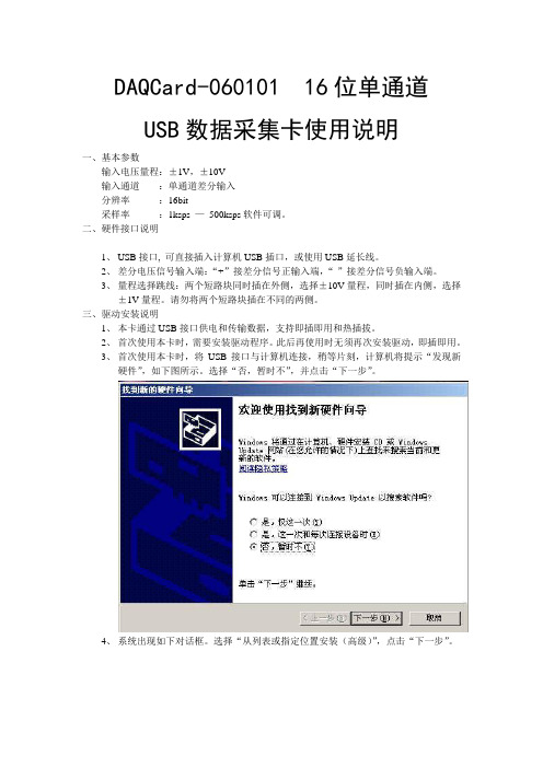
3、首次使用本卡时,将USB接口与计算机连接,稍等片刻,计算机将提示“发现新硬件”,如下图所示。
选择“否,暂时不”,并点击“下一步”。
4、系统出现如下对话框。
选择“从列表或指定位置安装(高级)”,点击“下一步”。
5、系统出现如下对话框。
选择“不要搜索。
我要自己选择安装的驱动程序”,点击下一步。
6、如出现下面的对话框,选择“通用串行总线控制器”,点击“下一步”。
7、系统出现如下对话框。
则点击“从磁盘安装”。
8、在弹出的路径对话框中选择程序安装目录下的“DAQCard-060101.Inf”文件。
点击“确定”。
9、回到6步所示对话框,此时出现提示“DAQCard(without driver)”,选中该项后,点击“下一步”。
10、系统开始安装驱动,若弹出如下对话框,选择“仍然继续”。
11、驱动安装完成,出现如下对话框,点击“完成”。
12、稍等片刻,系统再次提示安装驱动程序。
选择“否,暂时不”,点击“下一步”。
13、选择“自动安装软件”,点击“下一步”。
14、选中第二项驱动文件(如下图所示),点击“下一步”。
15、选择“仍然继续”。
16、驱动安装完成。
DAQ数据采集卡快速使用指南

DAQ数据撷取卡快速使用指南首先感您选购NI的DAQ产品,以下将简短地为您叙述快速安装与使用DAQ卡的步骤。
在安装DAQ的硬件之前,请您先确认是否安装了DAQ的驱动程序,基本上您的计算机必须有Measurement And Automation (MAX)来管理您所有的NI装置,另外您必须安装NI-DAQ 软件,目前建议安装最新的版本(您可利用光盘安装或是上网下载最新版本驱动程序.ni./support点选Drivers and Updates),新版驱动程序可支持大多数NI的DAQ卡片,包含S、E、M系列以及USB接口产品。
在安装完成NI-DAQ之后,您可以在桌面上发现有MAX应用程序,此时您可以关闭计算机,进行硬件安装,将PCI或是PCMCIA接口的DAQ卡片插入并重新开机,开机之后操作系统会自行侦测到该装置,并且自动安装驱动程序,依照对话框的带领便能顺利完成安装程序。
安装程序完成后,建议您开启MAX在Device and interface选项中会有Traditional DAQ 以及 DAQmx两个类别,那是依照您的卡片型号支持哪一种API而分类,一般而言,E系列卡片两种都支持,而M系列只支持DAQmx,S系列则不一定,在对应的Traditional DAQ或DAQmx中找到您的DAQ卡片型号,然后建议您先进行校正以及测试。
您可参考.ni./support/daq/versions确认您硬件适用的版本如何做校正与硬件测试:若需校正硬件,请于MAX中,您所安装的卡片型号上按鼠标右键选择self-calibration 即可,系统会对DAQ卡以现在温度做一次校正。
若需测试硬件,请于MAX中,您所安装的卡片型号上按鼠标右键选择Test Panels,然后选择所要测试的项目,并且依照接脚图将讯号连接妥当即可测试,建议您分别测试AI、AO、DI以及Counter。
接脚图:您可以在MAX中的DAQmx找到您所安装的卡片型号,并按鼠标右键,选择Device Pinout 便可以依照接脚图去连接相关接法,进行量测。
Pico Technology DrDAQ多功能数据采集仪说明书

多功能数据采集DrDAQ®使用灯光、声音和温度内置传感器使用标准电极测量 pH 值添加外部传感器和数字设备从一台 PC 上多达 20 个 DrDAQ 数据记录器捕捉数据通过 USB 连接和供电免费下载 PicoLog 6 和 PicoScope 6 软件免费软件开发工具包可下载示例程序免费技术支持 免费软件更新与 Windows、macOS 和 Linux 兼容传感器和指示器您的 DrDAQ 数据记录器可开箱即用;它具有内置的灯光、声音和温度传感器,以及一个您可以编程显示 1670 万种颜色其中任意一种颜色的 RGB LED 指示灯。
外部传感器插座还允许您扩展 DrDAQ 的功能。
使用内部传感器,您的 DrDAQ 可以测量湿度、氧气量、内部温度和更多值。
Pico Technology 可为您提供连接、使用以及甚至设计您自己的传感器所需要了解的一切。
不只是一款数据记录器由于 DrDAQ 的多功能性,您还可以将它用作示波器和频谱分析仪。
只需从下载和运行 PicoScope 软件,您的 DrDAQ 即可成为一个具有 100 kHz 带宽、8 位分辨率和能够测量高达 ±10 伏特电压的单通道示波器。
数字输入/输出DrDAQ 包含有 4 个数字输入/输出。
用作输入时,可为您提供更多的监控选项。
用作输出时,使您可以使用 DrDAQ 来控制外部设备。
其中两个数字输入/输出用作输入时包含有脉冲计数功能,并具有脉冲宽度调制 (PWM) 输出能力。
但这并非所有。
您的 DrDAQ 还包括一个信号发生器,可同时用作标准函数发生器和任意波形发生器 (AWG)。
AWG 功能使您可以创建自己的波形。
业余爱好者、学生或专业人士:DrDAQ 正是您所需DrDAQ 数据记录器具有每个人都需要的某些功能:无论您是在课堂中寻求有趣方式进行数据记录实验的教师、想要一种廉价数据记录方式和示波器的学生、想使用 C++ 监控实际设备输入和输出的程序员,想监控其环境的业余爱好者,还是想在实验室环境下测量 pH 值的专业人士,DrDAQ 都具有您所需的一切功能。
SmacqDAQSoftware快速使用指南
Smacq DAQ Software 快速使用指南关于Smacq DAQ SoftwareSmacq DAQ Software是Smacq为USB-3000和USB-5000系列数据采集卡开发的数据采集软件。
Smacq DAQ Software可以帮助没有编程经验的用户快速获取实验数据。
Smacq DAQ Software的设计主要是针对基础应用,对于复杂应用需要用户根据实际情况选择合适的开发环境,编程实现相关功能。
Smacq提供多种环境的开发范例和说明文档,如有需要请到自行下载或与service@取得联系。
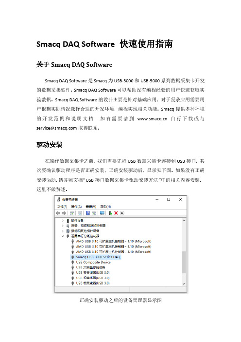
驱动安装在操作数据采集卡之前,我们需要先将USB数据采集卡连接到USB接口,其次要确认驱动程序是否正确安装,正确安装驱动后,显示见下图。
如果没有正确安装驱动,请参照文档“USB接口数据采集卡驱动安装方法”中的相关内容安装,这里不做赘述。
正确安装驱动之后的设备管理器显示图软件安装找到Smacq DAQ Softwave所在文件夹,双击运行setup.exe文件,一直下一步即可完成安装。
软件安装完成安装完成后,会在桌面创建快捷方式Smacq DAQ Softwave。
打开软件双击Smacq DAQ Software快捷方式打开软件。
打开软件后,点击Device List 按键,会在界面左侧显示连接到该电脑上的所有USB-3000和USB-5000系列数据采集卡的信息。
选择数据采集卡系列连接数据采集卡在设备选择列表中选择需要操作的采集卡,然后点击连接按键后,采集卡可以使用功能会激活。
连接数据采集卡功能说明Smacq DAQ Software有多种功能,详见下表。
YT模式采集卡连接后,点击YT按键,进入到YT模式。
YT模式是使用最多的功能,在YT模式中显示电压随时间变化的曲线。
在进行数据采集之前,需要选对采集卡进行设置。
YT模式模拟采集设置在YT模式中,点击设置进入YT-Config界面。
首先设置模拟输入的通道模式,根据硬件连接的方式进行选择,如果不清楚如果连接,可参考用户手册中3.2章节信号连接方式。
NI数据采集(DAQ)设备入门指南说明书

DAQ Getting Started GuideThis guide describes how to confirm your NI data acquisition (DAQ) device is operating properly. Install your application and driver software, then your device, using the instructions packaged with your device. Confirm Device RecognitionComplete the following steps:unch MAX by double-clicking the NI MAX icon on the desktop, or (Windows8) by clickingNI MAX from NI Launcher.2.Expand Devices and Interfaces to confirm your device is detected. If you are using a remoteRT target, expand Remote Systems, find and expand your target, and then expand Devices andInterfaces. If your device is not listed, press <F5> to refresh the configuration tree. If the device isstill not recognized, refer to /support/daqmx.For a Network DAQ device, do the following:•If the Network DAQ device is listed under Devices and Interfaces»Network Devices, right-click it and select Add Device.•If your Network DAQ device is not listed, right-click Network Devices, and select Find Network NI-DAQmx Devices. In the Add Device Manually field, type the Network DAQdevice’s host name or IP address, click the + button, and click Add Selected Devices. Yourdevice will be added under Devices and Interfaces»Network Devices.Note If your DHCP server is set up to automatically register host names, the device registers thedefault host name as cDAQ-<model number>-<serial number>, WLS-<serial number>,or ENET-<serial number>. You can find the serial number on the device. If you cannot find thehost name of that form, it may have been modified from the default to another value.If you still cannot access your Network DAQ device, click the Click here for troubleshootingtips if your device does not appear link in the Find Network NI-DAQmx Devices window orgo to /info and enter the Info Code netdaqhelp.Tip You can test NI-DAQmx applications without installing hardware by using an NI-DAQmxsimulated device. For instructions on creating NI-DAQmx simulated devices and importingNI-DAQmx simulated device configurations to physical devices, in MAX, select Help»Help Topics»NI-DAQmx»MAX Help for NI-DAQmx.3.Right-click the device and select Self-Test. When the self-test finishes, a message indicates successfulverification or if an error occurred. If an error occurs, refer to /support/ daqmx.4.For NI M and X Series PCI Express devices, right-click the device and select Self-Calibrate.A window reports the status of the calibration. Click Finish.Configure the Device SettingsSome devices, such as the NI-9233 and some USB devices, do not need properties for configuringaccessories, RTSI, topologies, or jumper settings. If you are installing only devices without configurable properties, skip to the next step. Configure each device with configurable settings that you install:1.Right-click the device name and select Configure. Be sure to click the device name under thefolder for the system (My System or Remote Systems) and NI-DAQ API in which you want tocontrol the device.For Network DAQ devices, click the device name and then the Network Settings tab to configurenetwork settings. For additional information on configuring Network DAQ devices, refer to yourdevice documentation.2.Configure the device properties.•If you are using an accessory, add the accessory information.•For IEEE 1451.4 transducer electronic data sheet (TEDS) sensors and accessories, configure the device and add the accessory as previously described. Click Scan for TEDS. To configureTEDS sensors cabled directly to a device, in MAX, right-click the device under Devices andInterfaces and select Configure TEDS.3.Click OK to accept the changes.Install Signal Conditioning or Switch DevicesIf your system includes SCXI signal conditioning modules, Signal Conditioning Components (SCC)such as SC carriers and SCC modules, terminal blocks, or switch modules, refer to the getting started guide for the product to install and configure the signal conditioning or switch hardware.Attach Sensors and Signal LinesAttach sensors and signal lines to the terminal block or accessory terminals for each installed device.You can find device terminal/pinout locations in MAX, the NI-DAQmx Help, or the devicedocumentation. In MAX, right-click the device name under Devices and Interfaces, and selectDevice Pinouts.For information about sensors, refer to /sensors. For information about IEEE 1451.4 TEDS smart sensors, refer to /teds. If you are using SignalExpress, refer to Use NI-DAQmx withYour Application Software.Run Test PanelsUse the MAX test panel as follows.1.In MAX, expand Devices and Interfaces or Devices and Interfaces»Network Devices.2.Right-click the device to test, and select Test Panels to open a test panel for the selected device.3.Click the tabs at the top and Start to test the device functions, or Help for operating instructions.4.If the test panel displays an error message, refer to /support.5.Click Close to exit the test panel.DAQ Getting Started Take an NI-DAQmx MeasurementNI-DAQmx Channels and TasksA physical channel is a terminal or pin at which you can measure or generate an analog or digital signal.A virtual channel maps a name to a physical channel and its settings, such as input terminal connections,the type of measurement or generation, and scaling information. In NI-DAQmx, virtual channels areintegral to every measurement.A task is one or more virtual channels with timing, triggering, and other properties. Conceptually, a taskrepresents a measurement or generation to perform. You can set up and save configuration information in a task and use the task in an application. Refer to the NI-DAQmx Help for complete information about channels and tasks.Use the DAQ Assistant to configure virtual channels and tasks in MAX or in your application software. Configure a Task Using the DAQ Assistant from MAXComplete the following steps to create a task using the DAQ Assistant in MAX:1.In MAX, right-click Data Neighborhood and select Create New to open the DAQ Assistant.2.In the Create New window, select NI-DAQmx Task and click Next.3.Select Acquire Signals or Generate Signals.4.Select the I/O type, such as analog input, and the measurement type, such as voltage.5.Select the physical channel(s) to use and click Next. the task and click Finish.7.Configure individual channel settings. Each physical channel you assign to a task receives a virtualchannel name. To modify the input range or other settings, select the channel. Click Details forphysical channel information. Configure the timing and triggering for your task. Click Run. Use NI-DAQmx with Your Application SoftwareThe DAQ Assistant is compatible with version 8.2 or later of LabVIEW, version 7.x or later ofLabWindows™/CVI™ or Measurement Studio, or with version 3 or later of SignalExpress.SignalExpress, an easy-to-use configuration-based tool for data logging applications, is at Start»AllPrograms»National Instruments»NI SignalExpress or (Windows8) NI Launcher.To get started with data acquisition in your application software, refer to the tutorials:Application Tutorial LocationLabVIEW Go to Help»LabVIEW Help. Next, go to Getting Started with LabVIEW»GettingStarted with DAQ»Taking an NI-DAQmx Measurement in LabVIEW.LabWindows/CVI Go to Help»Contents. Next, go to Using LabWindows/CVI»Data Acquisition»Taking anNI-DAQmx Measurement in LabWindows/CVI.Measurement Studio Go to NI Measurement Studio Help»Getting Started with the Measurement StudioClass Libraries»Measurement Studio Walkthroughs»Walkthrough: Creating aMeasurement Studio NI-DAQmx Application.SignalExpress Go to Help»Taking an NI-DAQmx Measurement in SignalExpress.© National Instruments3DAQ Getting Started GuideExamplesNI-DAQmx includes example programs to help you get started developing an application. Modifyexample code and save it in an application, or use examples to develop a new application or add example code to an existing application.To locate LabVIEW, LabWindows/CVI, Measurement Studio, Visual Basic, and ANSI C examples, go to /info and enter the Info Code daqmxexp. For additional examples, refer to .To run examples without hardware installed, use an NI-DAQmx simulated device. In MAX, selectHelp»Help Topics»NI-DAQmx»MAX Help for NI-DAQmx and search for simulated devices. TroubleshootingIf you have problems installing your software, go to /support/daqmx. For hardwaretroubleshooting, go to /support and enter your device name, or go to /kb.If you need to return your National Instruments hardware for repair or device calibration, refer to / info and enter the Info Code rdsenn to start the Return Merchandise Authorization (RMA) process.Go to /info and enter rddq8x for a complete listing of the NI-DAQmx documents and their locations.More InformationAfter you install NI-DAQmx, the NI-DAQmx software documents are accessible from Start»All Programs»National Instruments»NI-DAQ»NI-DAQmx document title or(Windows8) NI Launcher. Additional resources are online at /gettingstarted.You can access online device documentation by right-clicking your device in MAX and selecting Help»Online Device Documentation. A browser window opens to /manuals with the results of a search for relevant device documents. If you do not have Web access, documents for supported devices are included on the NI-DAQmx media.Worldwide Technical SupportFor support information, refer to /support for access to everything from troubleshooting and application development self-help resources to email and phone assistance from NI ApplicationEngineers. Visit /zone for product tutorials, example code, webcasts, and videos.Visit /services for NI Factory Installation Services, repairs, extended warranty, calibration, and other services.To ensure measurement accuracy, NI factory calibrates all applicable hardware and issues a BasicCalibration certificate, which you can get online at /calibration.Visit /training for self-paced training, eLearning virtual classrooms, interactive CDs,Certification program information, or to register for instructor-led, hands-on courses at locations around the world.For support available at the National Instruments worldwide offices, visit , or contact your local office at /contact. National Instruments corporate headquarters is located at 11500 NorthMopac Expressway, Austin, Texas, 78759-3504.DAQ Getting Started Refer to the NI Trademarks and Logo Guidelines at /trademarks for more information onNational Instruments trademarks. Other product and company names mentioned herein are trademarksor trade names of their respective companies. For patents covering National Instrumentsproducts/technology, refer to the appropriate location: Help»Patents in your software, thepatents.txt file on your media, or the National Instruments Patent Notice at /patents.You can find information about end-user license agreements (EULAs) and third-party legal notices inthe readme file for your NI product. Refer to the Export Compliance Information at /legal/export-compliance for the National Instruments global trade compliance policy and how toobtain relevant HTS codes, ECCNs, and other import/export data.© 2003–2013 National Instruments. All rights reserved.373737H-01Jul13。
VT280 便携式数据采集仪 DAQ 振动信号采集软件 使用说明书

VT280便携式数据采集仪DAQ振动信号采集软件深圳市森瑟科技发展有限公司广东省深圳市宝安区石岩街道创维创新谷5B栋8楼电话:*************网页:电邮:*****************.cn目录1. 数据采集基本知识 (2)2. 软件使用说明 (3)2.1选择文件路径 (3)2.2创建标定文件 (4)2.3高速数据采集 (4)2.4低速数据采集 (7)2.5示波+谱分析 (9)2.6转换文本格式 (10)2.7绘采集曲线图 (12)2.8绘阵列图曲线 (15)2.9绘频域曲线图 (16)1. 数据采集基本知识对于一些试验研究,需要把传感器输出的模拟电压或电流信号转换为数字量,输入到计算机进行后续分析。
要想把模拟信号转换为数字量,需要借助于模数转换,通常用“A/D”表示本仪器所配备的DAQ软件可支持多种数据采集卡、并口数据采集仪、USB数据采集仪、数字式应变仪等。
u数据采集精度数据采集设备的分辨率的高低能决定模数转换的精度,以采集设备的A/D转换分辨率为16Bits(16位)和12Bits(12位)对比,当最大量程都为±10伏时,转换精度对应关系是:模拟输入16位模数转换数字量12位模数转换数字量─────────────────────────────────+10伏32767 20480伏(对应于)0 0-10伏-32767 -2048─────────────────────────────────转化精度0.000305伏0.00488伏这时,数字量每变化1位相当于16位模拟量变化10V/32768»0.000305V;12位模拟量变化10V/4096»0.00488V。
可以看出,16位A/D转换比12位A/D精度高16倍。
u数据采集噪声任何A/D转换自身都有一定的噪声信号,当然,噪声信号越小越好,那么如何知道采集仪的噪声信号有多大呢?首先把采集仪的一个通道短接,然后通过采集程序看采集的数据的峰值,即可得到采集仪的本底噪声。
DAQ970A 数据采集系统用户指南
200
双线多路复用器
201
四线多路复用器
201
信号发送和多路复用
202
多路复用和切换中的误差源
203
制动器和通用开关
204
矩阵切换
206
RF 信 号 多 路 复 用
208
多功能模块
210
数字输入
210
数字输出
212
使用外部上拉电阻
213
驱动外部开关
213
积算器
214
积算器误差
215
模 拟 输 出 (DAC)
103
交流电压
105
直流电流
107
电阻
109
频率和周期
111
二极管
112
电容
113
DAQM907A 多 功 能 模 块 - 概 述
113
数 字 I/O (DIO) 通 道 (通 道 01 和 02)
114
积算器通道
117
DAC 输 出 和 感 测 通 道 (通 道 04 到 07)
118
被计算通道
120
废 弃 电 子 电 气 设 备 (WEEE)
本产品符合欧洲 WEEE 指令市场营销要求。贴附于产品上的标签(请见下方)指示,不得将本电气/电 子产品丢弃在家庭垃圾中。
产品类别:根据欧洲 WEEE 指令附件 1 中说明的设备类型,将本产品归为“监测和控制仪器”产品类 别。切勿丢弃在家庭垃圾中。
要退回不需要的产品,请与当地的 Keysight 办事处联系,或访问 /en/companyinfo/environment/takeback.shtml 以了解详细信息。
8
Keysight DAQ970A 用户指南
数据采集系统 Keysight DAQ970A DAQ973A 用户指南说明书
数据采集系统DAQ970A/DAQ973A此手册提供 Keysight DAQ970A/DAQ973A 数据采集系统的操作说明。
最新版本请始终参考英文版。
用户指南声明6版权声明6手册文档号6版本6发布者6软件修订版6担保说明7技术许可7限制性权限声明7废弃电子电气设备(WEEE)7符合性声明8安全和法规信息9安全注意事项9安全符号和法规标记10韩国A类EMC声明11产品法规及合规性12环境条件121仪器简介13仪器概览14前面板概览15仪器信号器16后面板概览17插件模块概览18尺寸图19远程接口配置20 Keysight IO Libraries Suite20 GPIB设置(仅限DAQ973A)20 LAN设置21 LAN服务27设置为默认值27 LAN重置27 Web界面28关于IP地址和点号的详细信息28 USB设置29技术连接详细信息30 LAN配置过程31固件更新33联系是德科技34 2快速入门35准备要使用的仪器36模块线路连接和安装37安装模块37卸载模块39连接电源和I/O电缆40打开仪器40开机自检40关闭仪器40使用内置帮助系统41查看帮助主题列表41查看前面板键的帮助信息422Keysight DAQ970A/DAQ973A用户指南查看仪器信息42调整提手43在机架中安装仪器44 Keysight BenchVue数据采集(DAQ)软件46 BenchVue数据采集(DAQ)软件许可46 3特征与功能47系统概述48数据采集系统概述48信号发送和切换52测量输入54多功能模块58控制输出59前面板菜单参考61 [Scan/Start]键63 [Monitor]菜单64数字65条形仪表66趋势图67直方图68 [Home]菜单70数据采集模式70 Strain offset71 Alarm output73帮助主题73 User settings74 [View]菜单77 Scan模式中的[View]菜单77 DMM Digitize或Digitizer模式中的[View]菜单82电源分析90 [View]菜单状态93 [Channel]菜单94多路复用模块:测量值94多路复用模块:开关模式130 DAQM907A-多功能模块133 DAQM909A-4通道24位数字转换器模块141被计算通道146使用外部仪器扫描151为通道添加标签152 [Interval]菜单153 Scan模式中的[Interval]菜单153 DMM Digitize模式中的[Interval]菜单156 Digitizer模式中的[Interval]菜单159 [Math]菜单163 mX+b标定163 %标定164 dBm标定164 dB标定165 [Copy]菜单166从单个通道复制/粘贴到单个通道(一对一)166从单个通道复制/粘贴到多个通道(一对多)167从多个通道复制/粘贴到多个通道(多对多)168 Keysight DAQ970A/DAQ973A用户指南3[Alarm]菜单169配置多路复用模块上的警报限值169配置多功能模块上的警报限值170警报限值指示171 [Utility]菜单173 Self Test173 Autocal173 Calibrate174 Security175 Admin175 [Module]菜单176 Scan List176 Card Reset177 Module Label177 Relay Cycle178 [Save Recall]菜单179 Manage Files179 Save180 Recall181设置为默认值181 Log to USB182 Save to USB185 Web界面187“Control Instrument”页面188“Configure LAN”页面188“Help”页面189模块概述190 DAQM900A20通道FET多路复用模块191 DAQM901A20通道衔铁式多路复用模块193 DAQM902A16通道舌簧式多路复用模块195 DAQM903A20通道制动器/通用开关模块197 DAQM904A4x8双线矩阵开关199 DAQM905A1:4双射频多路复用(50Ω)模块201 DAQM907A多功能模块203 DAQM908A40通道单端多路复用器206 DAQM909A4通道24位数字转换器模块208 4测量教程211系统电缆和连接212电缆规格212接地技术214屏蔽技术215高电平信号和低电平信号的分隔215系统电缆误差源215测量的基本知识219内部DMM219温度测量220直流电压测量228交流电压测量232电流测量238电阻测量240应变仪测量243 4Keysight DAQ970A/DAQ973A用户指南频率和周期测量246电容测量248数字化测量249电平触发251低电平信号的多路复用和切换252单线(单端)多路复用器252双线多路复用器253四线多路复用器253信号发送和多路复用254多路复用和切换中的误差源254制动器和通用开关256矩阵切换259 RF信号多路复用261多功能模块263数字输入263数字输出264使用外部上拉电阻265驱动外部开关265积算器266积算器误差267模拟输出(DAC)267继电器的使用寿命和预防性维护269Keysight DAQ970A/DAQ973A用户指南5声明声明版权声明©是德科技2019-2022根据美国和国际版权法,未经Keysight Technologies事先允许和书面同意,不得以任何形式或通过任何方式(包括电子存储和检索或翻译为其他国家或地区的语言)复制本手册中的任何内容。
LabVIEW DAQ助手数据采集教程

信号输入(数据采集)信号输入部分可以借助DAQ助手来实现,也可以使用DAQ通道来实现。
在NI-DAQmx 中,任务是包括一条或多条通道以及定时、触发等属性的集合。
从概念上来说,任务就是要进行的测量或生成。
例如,测量 DAQ设备一条或多条通道的温度就是一个任务。
在创建DAQ任务前,我们首先得初始化设备。
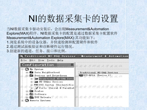
初始化设备要用到Mesurement&Automention Explorer(如图5.1所示为它的启动界面)。
按照下述步骤初始化设备。
图5.11.打开Mesurement&Automention Explorer。
2.在“配置”栏-“设备与接口”上单击鼠标右键,选择“新建…”,会出现如图5.2所示界面:图5.2由于没有硬件,这里用仿真设备,这里我们就选择“NI-DAQ仿真设备”,点“完成”后会出现如图5.3界面。
图5.33.点击“E系列DAQ”前面的“+”,展开栏目后如图5.4所示:图5.4这里我们选择“NI PCI-6071E”,点击“确定”后出现下图所示界面。
很容易发现,界面左边“配置”-“NI-DAQ设备”下多了一个“NI PCI-6071E”,单击它,右边的界面中出现它的配置参数,如图5.5所示。
图5.5经过以上步骤的设置,设备设备初始化完毕。
接下来我们就可以创建NI-DAQmx 任务了。
3.3.1.1创建NI-DAQmx任务按照下列步骤,可以创建并配置一个从 DAQ设备读取电压的任务。
方案1:利用DAQ助手1. 打开一个新建的空白 VI。
2. 在程序框图中,打开函数选板并选择 Express»输入,显示输入选板。
3. 选择输入选板上的“DAQ助手” Express VI,如左图所示。
将该Express VI 放置到程序框图上。
打开 DAQ助手,显示新建 Express任务对话框。
4. 单击采集信号»模拟输入,显示模拟输入选项。
5. 选择电压创建一个新的电压模拟输入任务。
Agilent U2300A Series USB模块多功能数据采集(DAQ)数据手册说明书
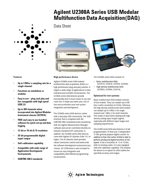
Agilent U2300A Series USB Modular Multifunction Data Acquisition(DAQ) Data SheetFeatures•Up to 3 MSa/s sampling rate for a single channel•Functions as standalone ormodular•Easy to use – plug-and-play and hot-swappable with high speedUSB 2.0•Up to 384 channels whenincorporated into Agilent ModularInstrument chassis (U2781A)•FREE and easy to use bundled software for quick set up and datalogging•12-bit or 16-bit A/D resolution •24-bit programmable digitalinput/output•Self-calibration capability •Compatible with wide range of Application DevelopmentEnvironments•USBTMC 488.2 standards High performance deviceAgilent U2300A series USB modularmultifunction data acquisition (DAQ) is ahigh performance plug-and-play solution. Ittargets a wide range of applications in bothindustrial and scientific environments. TheU2300A series DAQ devices providefunctionality that is much easier to use andcosts less. It helps you lower your cost oftest and accelerates your test systemintegration and development.The U2300A series DAQ devices comeswith a dual play USB connectivity. The USBinterface that is compliant with theUSBTMC 488.2 standards works seamlesslywith the Agilent Measurement Managersoftware and can be controlled remotely viaindustry standard SCPI commands. Inaddition, the U2300A series DAQ devicescome with Agilent IO Libraries Suite 14.2 orhigher. The IO Libraries Suite providesrobust instrument control and works withthe software development environment youchoose. IVI-COM driver is also included toensure an easy integration andcompatibility with different programmingenvironments.The U2300A series DAQ consists of:•Basic multifunction DAQ(U2351A, U2352A, U2353A, U2354A)•High density multifunction DAQ(U2355A, U2356A, U2331A)Optimized for test systemsBasic multifunction DAQ module consistsof four models. They can sample up to 500kSa/s with a resolution of 16 bits. Whereas,the high density multifunction DAQ modulecan sample up to 3 MSa/s for singlechannel and 1 MSa/s for multi channels.This makes it ideal when dealing with highdensity analog input/output signals,especially with different input ranges andsampling requirements.The U2300 series DAQ also features a 24-bitprogrammable I/O lines and 2 independent31 bits general purpose digital counter. Inaddition to that, this series of DAQ is able toperform analog and digital functions at fullspeed. It has a resolution of 12 or 16 bits,with no missing codes. It is also equippedwith self-calibration capability. This enablesthe device to re-adjust its offset within thespecified accuracy and ranges.Agilent TechnologiesModules provide flexible system stimulus and controlPolling and continuous mode - TheU2300A series DAQ provides two modes, which are the polling and continuous modes.Trigger sources - None (intermediate trig-ger),analog/external digital trigger, SSI/ star trigger and master/slavetrigger sources. You can configure all these trigger sources for A/D and D/A operations. Master/slave trigger and SSI/Start Trigger are recommended when used with the Agilent U2781A modular instrument chassis.Predefined function generator - Sine-wave, square-wave, triangle wave, sawtooth and noise waveforms.Burst mode - Incorporated to simulate simultaneous analog input.Arbitary waveform - Arbitary waveform generation through user’s input.Remote access and controlThe built-in user interface providesremote access and control of the U2300series DAQ instruments via the AgilentMeasurement Manager software andSCPI commands. Using the software, youcan:•View and modify instrument setup•Send trigger signals to instrument•Open, close, or monitor I/O channels•Send SCPI commands via Agilent IOLibraries 14.2 Suite or higher.Works with your choice of softwareThe Agilent U2300A series USB modularmultifunction DAQ works with yourchoice of software so you can save timeand this preserves your software andhardware investments. Program directlywith SCPI, or use the IVI-COM softwaredriver that provide compatibility with themost popular development environmentsand tools as listed below:•Agilent VEE, Agilent T&M T oolkit•Microsoft Visual , C/C++and Visual Basic 6•LabVIEW•MATLABFor more information, please visit/find/DAQ.Figure 1The Agilent Measurement Manager software user interfaceELECTRICAL SPECIFICATIONS Basic Multifunction USB DAQ[1] System Scynchronous Interface (SSI) and Star Trigger commands are used when the modular device is incorporated into the chassis.[2] Maximum external reference voltage for analog output channels (AO_EXT_REF) is ±10 V.[3] 20 minutes warm-up time is recommended.High Density Multifunction USB DAQ[1] System Scynchronous Interface (SSI) and Star Trigger commands are used when the modular device is incorporated into the chassis.[2] Maximum external reference voltage for analog output channels (AO_EXT_REF) is ±10 V.[3] 20 minutes warm-up time is recommended.ELECTRICAL MEASUREMENT SPECIFICATIONSBasic Multifunction USB DAQHigh Density Multifunction USB DAQAnalog Input Measurement [1]Model NumberU2351A/U2352AU2353A/U2354AFunction 23 °C ± 5 °C0 °C to 18 °C 28 °C to 45 °C 23 °C ± 5 °C0 °C to 18 °C 28 °C to 45 °C Offset Error ±1 mV ±5 mV ±1 mV ±5 mV Gain Error±2 mV ±5 mV±2 mV ±5 mV–3dB small signal bandwidth 760 kHz 1.5 MHz 1% THD large signal bandwidth 300 kHz300 kHzSystem noise 1 mVrms 2 mVrms1 mVrms 2.5 mVrmsCMRR62 dB 62 dB Spurious-free dynamic range (SFDR)88 dB 82 dB Signal-to-noise and distortion ratio (SINAD)80 dB78 dBT otal harmonic distortion (THD)–90 dB –88 dB Signal-to-noise ration (SNR)80 dB 78 dB Effective number of bits (ENOB)1312.6Analog Output Measurement [1]Model NumberU2351A/U2353AFunction 23 °C ± 5 °C0 °C to 18 °C 28 °C to 45 °C Offset Error ±1 mV ±4 mV Gain Error ±4 mV ±5 mVSlew rate 19 V/µsRise time 0.7 µs 0.8 µs Fall time0.7 µs 0.8 µsSettling time to 1% output error 4 µs Driving capability 5 mA Glitch energy5 ns-V (typical),80 ns-V (maximum)Analog Input Measurement [1]Model NumberU2355A U2356A U2331AFunction 23 °C ± 5 °C 0 °C to 18 °C 28 °C to 45 °C 23 °C ± 5 °C 0 °C to 18 °C 28 °C to 45 °C 23 °C ± 5 °C 0 °C to 18 °C28 °C to 45 °C Offset Error ±1 mV ±2 mV ±1 mV ±2 mV ±2 mV ±3 mV Gain Error ±2 mV ±3 mV ±2 mV ±6 mV ±6 mV ±7.5 mV –3dB small signal bandwidth 760 kHz 1.3 MHz 1.2 MHz 1% THD large signal bandwidth 400 kHz 400 kHz N/A System noise 1 mVrms 2 mVrms 1 mVrms 4 mVrms 3 mVrms 5 mVrms CMRR 64 dB 61 dB 62 dB Spurious-free dynamic range (SFDR)88 dB 86 dB 71 dB Signal-to-noise and distortion ratio (SINAD)80 dB 78 dB 72 dB T otal harmonic distortion (THD)–90 dB –90 dB –76 dB Signal-to-noise ration (SNR)80 dB 78 dB 72 dB Effective number of bits (ENOB)1312.611.6[1] Specifications are for 20 minutes of warm-up time, calibration temperature at 23 °C and input range of ±10 V.TEST CONDITIONS[2] DUT setting at ±10 V bipolar.Analog Output Measurement [1]Model NumberU2355A/U2356AU2331AFunction 23 °C ± 5 °C0 °C to 18 °C 28 °C to 45 °C 23 °C ± 5 °C0 °C to 18 °C 28 °C to 45 °C Offset Error ±1 mV ±4 mV ±1.5 mV ±3 mV Gain Error ±4 mV ±5 mV±4 mV ±5 mVSlew rate 19 V/µs19 V/µsRise time 0.7 µs 0.8 µs 0.7 µs 0.8 µs Fall time0.7 µs 0.8 µs0.7 µs 0.8 µsSettling time to 1% output error 4 µs 4 µs Driving capability 5 mA 5 mA Glitch energy5 ns-V(Typical),80 ns-V (Maximum)5 ns-V(Typical),80 ns-V (Maximum)Dynamic Range TestModel Number Test Conditions [2]SFDR, THD, SINAD, SNR, ENOBU2351A U2352A U2355A Sampling rate:Fundamental frequency:Number of points:Fundamental input voltage: 250 kSa/s 2.4109 kHz 8192FSR –1 dB FS U2353A U2354A U2356A Sampling rate:Fundamental frequency:Number of points:Fundamental input voltage:500 kSa/s 4.974 kHz 16384FSR –1 dB FS U2331ASampling rate:Fundamental frequency:Number of points:Fundamental input voltage:3 MSa/s 29.892 kHz 65536FSR –1 dB FSDynamic Range Test Model Number Test Conditions [2] •–3dB small signal bandwidth •1% THD large signal bandwidthU2351A U2352A U2355A Sampling rate:Input voltage:•–3dB small signal bandwidth •1% THD large signal bandwidth 250 kSa/s 10% FSR FSR –1 dB FS U2353A U2354A U2356A Sampling rate:Input voltage:•–3 dB small signal bandwidth •1% THD large signal bandwidth 500 kSa/s 10% FSR FSR –1 dB FS U2331ASampling rate:Input voltage:•–3 dB small signal bandwidth •1% THD large signal bandwidth3 MSa/s 10% FSR FSR –1 dB FSGENERAL SPECIFICATIONSREMOTE INTERFACE USB 2.0 High Speed USBTMC Class Device POWER CONSUMPTION +12 VDC, 550 mA maximumOPERATING ENVIRONMENTOperating temperature from 0 °C to +55 °CRelative humidity at 15% to 85% RH (non-condensing) Altitude up to 4600 meters STORAGE COMPLIANCE –20 °C to +70 °CSAFETY COMPLIANCE Certified with:•IEC 61010-1:2001/EN 61010-1:2001 (2nd Edition)•USA: UL61010-1: 2004•Canada: CSA C22.2 No.61010-1:2004EMC COMPLIANCE Certified with:•IEC/EN 61326-1 1998•CISPR 11: 1990/EN55011:1991 , Group 1, Class A •CANADA: ICES-001: 1998•Australia/New Zealand: AS/NZS 2064.1SHOCK and VIBRATION T ested to IEC/EN 60068-2IO CONNECTOR68-pin female VHDCI TypeDIMENSION (WxDxH)•120 mm x 182.40 mm x 44 mm (with plastic casing)•105 mm x 174.54 mm x 25 mm (without plastic casing)WEIGHT•565 g (with plastic casing)•400 g (without plastic casing)WARRANTY One yearStandard Shipped Components:•USB Interface Cable•L-Mount Kit (used with modular instrument chasis) •Quick Start G uide •Certificate of Calibration (CoC) •Product Reference CD-ROM•Agilent IO Libraries Suite 14.2 CD-ROMPRODUCT OVERVIEWFRONT VIEWREAR VIEWTOP VIEW120 mmSOFTWARE REQUIREMENTSAgilent connectivity software included Agilent IO Libraries Suite 14.2Minimum system requirements (IO libraries and drivers)PC hardware 500 MHz Pentium III or higher, 256 MB RAM,40 GB hard disk space, CD-ROM drive Operating System Windows 2000 and above Computer Interface USB 2.0 high SpeedSoftware driver : IVI-COMCompatible with programming environments:Agilent VEE, Agilent T&M Toolkit Microsoft Visual , C/C++ Visual Basic 6 LabVIEW MATLABOptional Accessories:•U2901A - Terminal Board with SCSI-II 68 pin connector with 1 meter cable •U2902A - Terminal Board with SCSI-II 68 pin connector with 2 meter cable •U2781A 6-slot USB Modular Instrument Chassis182.40 mmAgilent Technologies’ Test and Measurement Support, Services, and AssistanceAgilent Technologies aims to maximize the value you receive, while minimizing your risk and problems. We strive to ensure that you get the test and measurement capabilities you paid for and obtain the support you need. Our extensive support resources and services can help you choose the right Agilent products for your applications and apply them successfully. Every instrument and system we sell has a global warranty. Two concepts underlie Agilent’s overall support policy: “Our Promise” and “Your Advantage.”Our PromiseOur Promise means your Agilent test and measurement equipment will meet its advertised performance and functionality. When you are choosing new equipment, we will help you with product information, including realistic performance specifications and practical recommendations from experienced test engineers. When you receive your new Agilent equipment, we can help verify that it works properly and help with initial product operation. Your AdvantageYour Advantage means that Agilent offers a wide range of additional expert test and measurement services, which you can purchase according to your unique technical and business needs. Solve problems efficiently and gain a competitive edge by contracting with us for calibration, extra-cost upgrades, out-of-warranty repairs, and on-site education and training, as well as design, system integration, project management, and other professional engineering services. Experienced Agilent engineers and technicians worldwide can help you maximize your productivity, optimize the return on investment of your Agilent instruments and systems, and obtain dependable measurement accuracy for the life of those products.Agilent Email Updates/find/emailupdatesGet the latest information on the products and applications you select.Agilent Direct/find/agilentdirectQuickly choose and use your test equipment solutions with confidence.For more information on Agilent Technologies’ products, applications or services, please con-tact your local Agilent office. The complete list is available at:/find/contactusPhone or FaxUnited States:(tel) 800 829 4444(fax) 800 829 4433Canada:(tel) 877 894 4414(fax) 800 746 4866China:(tel) 800 810 0189(fax) 800 820 2816Europe:(tel) 31 20 547 2111Japan:(tel) (81) 426 56 7832(fax) (81) 426 56 7840Korea:(tel) (080) 769 0800(fax) (080) 769 0900Latin America:(tel) (305) 269 7500Taiwan:(tel) 0800 047 866(fax) 0800 286 331Other Asia Pacific Countries:(tel) (65) 6375 8100(fax) (65) 6755 0042Email:*****************Product specifications and descriptions in this document subject to change without notice.© Agilent Technologies, Inc. 2006Printed in USA, 29 September, 20065989-5626ENAgilent Technologies。
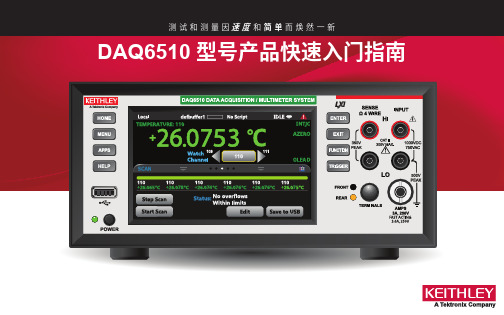
基尔希 型号DAQ6510 数据采集卡 快速入门指南说明书
安全性预防措施在使用本产品以及任何相关仪器前请遵守以下安全性预防措施。
虽然一些仪器及其配件可在非危险电压下正常操作使用,但在某些例外情况下仍可能会出现危险的状况。
只应该由能够识别电击危险,并熟悉必需安全性预防措施以避免可能发生的伤害的人员使用本产品。
在使用本产品之前,请仔细阅读并遵照所有安装、操作及维护信息。
有关完整的产品技术规格,请参阅用户文档。
如果没有按照规定的方式使用产品,则产品所提供的保护功能有可能会被削弱。
产品用户的类型包括:安全责任主体,可以是个人或者部门,对设备的使用和维护负责,责任主体需确保设备在其规定和运行能力内使用并确保操作人员经过了充分的培训。
操作人员只能将本产品用于预期功能。
操作人员需经过电气安全措施培训和本仪器的正确使用培训。
操作人员应得到电击保护并且防止接触到危险的带电电路。
维护人员对产品执行日常维护以确保正常运行,例如,设置线路电压或更换耗材。
用户文档中说明了维护步骤。
如果可由操作人员执行这些步骤,步骤中明确进行了说明。
否则,只应由维修员执行。
维修人员经过培训,能够处理带电电路,执行安全安装,以及修理产品。
只有经过正确培训的维修员才能执行安装和维修步骤。
Keithley Instruments 产品经过专门设计,可与测量、控制和数据 I/O 连接的电子信号共同使用,带有低瞬时过压,不得直接连接到市电电源或带有高瞬时过压的电压电源。
测量类别 II(请参考 IEC 60664)连接需要通常与本地交流市电电源连接相关的高瞬时过压保护。
某些 Keithley Instruments 测量仪器可能要连接到市电电源。
这些仪器将被标记为类别 II 或更高。
除非技术规格、操作手册和仪器标签上明确允许,否则不要将任何设备连接到市电电源。
存在电击危险时要格外小心。
电缆连接器插孔或测试夹具可能存在致命电压。
美国国家标准学会 (ANSI) 声明当电压电平超过 30 V RMS、42.4 V PEAK 或 60 VDC 时存在电击危险。
NI的数据采集卡的daq
NI-DAQmx模拟I/O实例
使用MAX创建任务实例。虚拟出一块NI PCI-6530数据采集卡,并在MAX中创建 一个测量任务,基于热电偶对温度进行测量,该任务包含有两个虚拟通道, 一个为全局虚拟通道,另一个为局部虚拟通道。具体步骤如下: • 创建虚拟数据采集卡:打开MAX,选择M系列的数据采集卡中的PCI-6320。 • 创建全局虚拟通道:在MAX左侧Configuration配置导航栏“My System”下的 “Data Neighborhood”上单击鼠标右键,从右键菜单中选择“Creat New…” 后,在弹出的对话窗口中选择“NI-DAQmx Global Virtual Channel”,然后单 击“next”按钮。在界面中选择测量类型。 • 选择后单击“Next”按钮,下一界面中要求填入欲创建的虚拟通道的名称。 • 创建任务:在MAX左侧Configuration配置导航栏“My System”下的“Data Neighborhood”上单击鼠标右键,从右键菜单中选择“Creat New…”后,在弹 出的对话窗口中选择“NI-DAQmx Task”,然后单击“next”按钮。 • • • • 同样会出现要求选择测量类型的界面。 单击“Next”按钮确认后,在下一界面中 填入欲创建的任务名称。 在任务中新建局部虚拟通道:包括添加 局部虚拟通道,更改触发和计时信息等。 单击窗口上方的“Run”按钮,就可以开 始数据采集了。至此一个具有两个虚拟 通道(一个为全局通道,一个为虚拟通 道)、用于通过热电偶测量温度的任务 就创建并配置完毕了。
模拟输入单点采集及VI实现
本例的基本实现步骤如下。 步骤1、新建一个名为“单通道单 点采集.vi”的VI,并添加AI Sample Channel.vi,配置为使用设备1、通 道0、-10~+10V电压范围进行单点 采集。添加While循环和等待函数, 使得采集可以持续进行,每3秒钟 采集一次。 步骤2、新建一个名为“多通道单 点采集.vi”的VI,并仿照上一步骤 编辑程序,不同之处在于添加的 VI为AI Sample Channels.vi,配置 为使用通道0~7共8个通道进行采 集,采集数据在送入波形图表之 前需先从数组类型转换为簇类型 数据。
DAQ-USB-2K1数据采集卡-用户手册
USB+卡 说明书
深圳市中科鸥鹏智能科技有限公司 2011-8-18
Page 1 of 20
DAQ-USB-2K1 数据采集卡用户手册
目录
一、 概述 ...................................................................................................................................................3 二、 技术指标 ...........................................................................................................................................3 1、 USB 指标 ........................................................................................................................................3 2、 模入部分( 标*为出厂标准状态,下同 )..................................................................................3 3、 开关量部分 .............................................................................................................................
DAQ 入门指南说明书

DAQ入门指南本文档介绍如何确保NI数据采集(DAQ)设备正常工作。
首先安装应用程序和驱动程序,然后按照设备随附的安装须知安装设备。
确认设备识别请完成下列步骤:1.在桌面上双击NI MAX图标,在(Windows 8)操作系统中,在NI启动器中单击NI MAX,均可打开MAX。
2.展开设备和接口,确认设备已被识别。
如使用远程实时终端,展开远程系统,找到并展开远程终端,然后打开设备和接口。
如设备未显示,可按<F5>刷新配置目录树。
如设备仍未显示,请访问/support/daqmx。
如使用网络DAQ设备,请按下列步骤操作:•如网络DAQ设备在设备和接口»网络设备下,右键单击并选择添加设备。
•如未显示网络DAQ设备,右键单击网络设备并选择查找网络NI-DAQmx设备。
在手动添加设备栏中,输入网络DAQ设备的主机名称或IP地址,单击+按钮和添加所选设备。
添加的设备会出现在设备和接口»网络设备下。
注如DHCP服务器被设置为自动注册主机名称,设备的名称将被注册为cDAQ-<型号>-<序列号>、WLS-<序列号>或ENET-<序列号>。
设备上标有设备序列号。
如未找到上述形式的主机名称,默认主机名称可能已改为其他值。
如仍无法访问网络DAQ设备,单击查找网络NI-DAQmx设备窗口的如未显示设备,单击此处可获取疑难解答提示信息链接,或访问/info,输入信息代码netdaqhelp查询。
提示通过NI-DAQmx仿真设备,无需安装硬件即可测试NI-DAQmx应用程序。
关于在MAX中创建NI-DAQmx仿真设备和导入NI-DAQmx仿真设备配置至物理设备的详细信息,选择帮助»帮助主题»NI-DAQmx»NI-DAQmx的MAX帮助。
3.右键单击设备名并选择自检。
自检结束后将弹出一个窗口显示设备通过验证或出现错误。
USB_DAQ_XF4626同步数据采集卡使用说明书

8路高速高步数据采集卡(USB_DAQ_XF4626)使用说明一.接口及接线说明:按图中箭头方向,从上到下,16个接线端子,依次是:AIN0、AIN1、AIN2、AIN3、AIN4、AIN5、AIN6、AIN7、GND、DI0、DI1、DI2、DI3、DI4、VOH、AGND。
1. AIN0-AIN7为8路同步电压信号,电压信号检测范围:-5V~+5V,-10V~+10V,可以通过软件选择,信号电压值不能大于16V,否则会烧坏AD;2. DI0-DI4为5路开关量输入检测,兼容TTL电平,默认为高电平。
3. VOH为采集卡稳压输出,电压范围为0-24V,默认已调为12V,方便给传感器等外接电路供电,但要注意切勿发生短路;4. 其他功能如DA、PWM、DO、脉冲测量等,敬请期待即将推出的多功能版;二.软件使用说明:1.安装驱动程序用USB线连接采集卡到电脑,弹出的找到新硬件向导,选择从列表或指定位置安装(高级)(S),点击下一步。
(此USB芯片有2个USB口,A和B,分别安装即可)点击“浏览”,找到“USB驱动程序”文件夹,确定。
如下图所示,然后点击“下一步”。
如弹出如下对话框,请选择“浏览”并找到USB驱动文件夹中的文件ftdibus.sys,32位系统请安装“32位系统”文件夹中对应驱动,64位系统请安装“64位系统”文件夹中对应驱动。
确定,即可自动进行USB驱动程序的安装,如下图所示:USB驱动程序安装成功以后,弹出如下图所示对话框:此时,还会弹出USB_B口的驱动安装,操作同上。
USB驱动程序安装成功以后,可以在设备管理器中查看,在“通用串行总线控制器”中,可以看到如下图红框中所示的2个USB设备。
注意:如果设备管理器中没有看到USB设备,请重新安装USB驱动程序。
2.打开Labview上位机数据采集软件或打包好的EXE,采集数据按照接线说明,连接信号线,可同时实时测量和控制所有模拟量和数字时的变化。
DAQ资料撷取卡快速使用指南

資料擷取卡快速使用指南首先感謝您選購的產品,以下將簡短地為您敘述快速安裝與使用卡的步驟。
在安裝的硬體之前,請您先確認是否安裝了的驅動程式,基本上您的電腦必須有()來管理您所有的裝置,另外您必須安裝軟體,目前建議安裝最新的版本(您可利用光碟安裝或是上網下載最新版本驅動程式點選),新版驅動程式可支援大多數的卡片,包含、、系列以及介面產品。
在安裝完成之後,您可以在桌面上發現有應用程式,此時您可以關閉電腦,進行硬體安裝,將或是介面的卡片插入並重新開機,開機之後作業系統會自行偵測到該裝置,並且自動安裝驅動程式,依照對話框的帶領便能順利完成安裝程序。
安裝程序完成後,建議您開啟在選項中會有以及兩個類別,那是依照您的卡片型號支援哪一種而分類,一般而言,E系列卡片兩種都支援,而M系列只支援,S系列則不一定,在對應的或中找到您的卡片型號,然後建議您先進行校正以及測試。
您可參考確認您硬體適用的版本如何做校正與硬體測試:若需校正硬體,請於中,您所安裝的卡片型號上按滑鼠右鍵選擇即可,系統會對卡以現在溫度做一次校正。
若需測試硬體,請於中,您所安裝的卡片型號上按滑鼠右鍵選擇,然後選擇所要測試的項目,並且依照接腳圖將訊號連接妥當即可測試,建議您分別測試、、以及。
接腳圖:您可以在中的找到您所安裝的卡片型號,並按滑鼠右鍵,選擇便可以依照接腳圖去連接相關接法,進行量測。
接線模式( ):接線模式一般有分為、、三種,其中以最為準確,但此模式需要一次使用掉兩個,一般而言,選擇模式時,以為例,您要將訊號正極接到並將負極接到,則量測到的值便是以減掉,原則上就是正極接負極就接。
至於接線方式則是將正極連到某並將負極連到,此方式較為不準確,而且不適用於有接地的訊號量測。
則與相似,除了連接正極訊號之外,您要將負極接到,適合量測有接地訊號。
偏壓電組:當您的量測值有偏移或是明顯雜訊時,請確認改用的接線模式,如果仍然有雜訊或是數值偏移,請在負極接點處直接再連一條歐姆的電阻到,此電阻稱為偏壓電阻,偏壓電阻應該可以有效改善量測精確度。
NI-DAQ快速入门指南(中文)
3
NI-DAQ 7.0 快速入门指南
查对 NI-DAQ 7.0 的 Readme 文件中所列出的 NI-DAQ 7.0 支持的操作系统、应用 软件、编程语言和设备,以了解在你的应用中要安装和使用 NI-DAQ 7.0 哪些部分。 如果你现有的应用中包含不被支持的部分,请你不要安装 NI-DAQ 7.0。
»
粗体字 斜体字 等宽字体 等宽字体黑体 等宽字体斜体字
下列约定适用于本手册: 该标志引导您进入子目录及从对话框选项中选择执行最终操作。如菜单 File>>Page Setup>>Options 即告诉您按下 File 菜单,选择 Page Setup 选 项,最终选取 Options 执行。
这个图标表示提示,即给您一些参考信息。
的帮助》专利、你CD上的patents.txt文件或者/patents
323235A-01
©2003 National Instruments (NI) 版权所有
2003年4月
约定
步骤 13. 运行测试面板.....................................................................................20 步骤 14. 配置所有附加的新设备.....................................................................21 步骤 15. 配置通道和任务.................................................................................21
在 NI-DAQmx 中配置任务....................................................................22 为 NI-DAQmx 配置全局通道................................................................24 为传统 NI-DAQ 配置虚拟通道.............................................................24 着手开发应用程序............................................................................................. 25 范例 ......................................................................................................... 25 有关测量应用程序和设备的信息 .........................................................26 在同一台计算机上使用传统 NI-DAQ 和 NI-DAQmx ..................................28 NI-DAQ 7.0 支持的操作系统、应用软件、编程语言和设备.......................30 支持的操作系统 ..................................................................................... 30 支持的应用软件和编程语言 .................................................................30 支持的设备 ............................................................................................. 31
- 1、下载文档前请自行甄别文档内容的完整性,平台不提供额外的编辑、内容补充、找答案等附加服务。
- 2、"仅部分预览"的文档,不可在线预览部分如存在完整性等问题,可反馈申请退款(可完整预览的文档不适用该条件!)。
- 3、如文档侵犯您的权益,请联系客服反馈,我们会尽快为您处理(人工客服工作时间:9:00-18:30)。
DAQ数据撷取卡快速使用指南
首先感您选购NI的DAQ产品,以下将简短地为您叙述快速安装与使用DAQ卡的步骤。
在安装DAQ的硬件之前,请您先确认是否安装了DAQ的驱动程序,基本上您的计算机必须有Measurement And Automation (MAX)来管理您所有的NI装置,另外您必须安装NI-DAQ 软件,目前建议安装最新的版本(您可利用光盘安装或是上网下载最新版本驱动程序.ni./support点选Drivers and Updates),新版驱动程序可支持大多数NI的DAQ卡片,包含S、E、M系列以及USB接口产品。
在安装完成NI-DAQ之后,您可以在桌面上发现有MAX应用程序,此时您可以关闭计算机,进行硬件安装,将PCI或是PCMCIA接口的DAQ卡片插入并重新开机,开机之后操作系统会自行侦测到该装置,并且自动安装驱动程序,依照对话框的带领便能顺利完成安装程序。
安装程序完成后,建议您开启MAX在Device and interface选项中会有Traditional DAQ 以及 DAQmx两个类别,那是依照您的卡片型号支持哪一种API而分类,一般而言,E系列卡片两种都支持,而M系列只支持DAQmx,S系列则不一定,在对应的Traditional DAQ或DAQmx中找到您的DAQ卡片型号,然后建议您先进行校正以及测试。
您可参考.ni./support/daq/versions确认您硬件适用的版本
如何做校正与硬件测试:
若需校正硬件,请于MAX中,您所安装的卡片型号上按鼠标右键选择self-calibration 即可,系统会对DAQ卡以现在温度做一次校正。
若需测试硬件,请于MAX中,您所安装的卡片型号上按鼠标右键选择Test Panels,然后选择所要测试的项目,并且依照接脚图将讯号连接妥当即可测试,建议您分别测试AI、AO、DI以及Counter。
接脚图:
您可以在MAX中的DAQmx找到您所安装的卡片型号,并按鼠标右键,选择Device Pinout 便可以依照接脚图去连接相关接法,进行量测。
接线模式(Input Configuration):接线模式一般有分为Differential、RSE、NRSE三种,其中以Differential最为准确,但此模式需要一次使用掉两个channel,一般而言,选择Differential模式时,以channel 0为例,您要将讯号正极接到channel 0并将负极接到channel 8,则量测到的值便是以channel 0减掉channel 8,原则上就是正极接channel n
负极就接channel n+8。
至于RSE接线方式则是将正极连到某channel并将负极连到ground,此方式较为不准确,而且不适用于有接地的讯号量测。
NRSE则与RSE相似,除了连接正极讯号之外,您要将负极接到AISENSE,NRSE适合量测有接地讯号。
偏压电组:当您的DAQ量测值有偏移或是明显噪声时,请确认改用Differential的接线模式,如果仍然有噪声或是数值偏移,请在负极接点channel n+8处直接再连一条100K奥姆的电阻到AI GND,此电阻称为偏压电阻,偏压电阻应该可以有效改善量测精确度。
在LabVIEW中使用DAQ小帮手快速建立基本应用:
首先开启LabVIEW然后在程序区中拖曳出DAQ小帮手,将DAQ Assistant放到白色的程序区后,会出现如下画面:
接着以量测电压值的输入为例,选择Analog Input再选择Voltage,然后选择所要使用的信道,图中例是使用ai0到ai3总共四个通道作撷取,选择完毕按下Finish。
接着会出现如下画面,您可以在此设定您的取样速率(若设为100000,表示每秒取十万个数值,但现在因为有四个信道所以每个信道会分别取到25000个点,换言之,各别通道本身所取样的点与点之时间间隔为十万分之四秒),此外您可以设定所要量测的讯号大小围,建议您的围是略大于讯号极值,如此可以将量测的准确度与分辨率最佳化。
在此您也可以设定您的量测接线模式与取样动作的方式,除非您需要动用该DAQ卡片超过一半的信道,否则强烈建议您使用Differential方式,另外取样动作模式有分为撷取单一点(每执行一次程序只抓一点),有限的多点撷取(可以设定要抓多少点,程序会依照您设定的取样速度抓到您所要求的点数),以及连续撷取。
画面中以连续撷取为例,取样速率为100000,每次呈现5000个点,量测围-3到7伏特之间。
当设定完成之后,按下OK计算机会自动完成设定工作,出现如下画面:
图中淡蓝色DAQ Assistant会自动出现,但我们必须手动加上外围的循环,并且连上一个Graph让抓到的数据可以显示出来,右边就是人机接口中数据显示的画面。
DAQ小帮手也可以做计数器输出入、数字讯号输出入以及模拟输出的设定,其设定方法与AI 小异,您可以自行尝试看看。
常见问题:
1.我不是使用LabVIEW,请问要去哪里才能找到C或VB的例程序?
答:在我的计算机中,路径
C:\Program Files\National Instruments\NI-DAQ\Examples下面都有各种语言的例程序。
当然您必需先安装特定的程序语言(如VB、VC等),您才能在NI-DAQ安装过程中勾选该程序语言的例程序,安装完成后,您也才能顺立的开启特定程序语言的DAQ例。
2.为何我的DAQ装置在MAX看不到?
答:如果您的DAQ是使用USB接口的,或许它是DAQmx BASE的系统,那必须在开始程序集中的DAQmx BASE中做设定,不过现在最新版本的DAQ驱动程序也已经能够支持了,所以建议您可以下载最新版本安装,这样在MAX中就可以看到这项装置。
3.量测值不准确么办?
答:您可以先确认是否选用Differential模式(差动模式),如果已经是使用Differential模式,那么可以在讯号负极接脚处,再连接一条100K奥姆的电阻到模拟接地处,这会使量测值更稳定准确,如果还是有相同问题存在,则可以检查是否有强烈噪声在附近干扰,尤其像马达之类的高电磁场装置附近。
若您是从Sensor传感器来取得数据,您亦可考虑使用NI的SCXI(多通道)或SCC(少信道)讯号处理设备。
4.DAQ的精确度如何计算?
答:首先您要先知道您的量测需分辨率到多少,通常卡片会有多少位分辨率,如16bit 的规格,您可以把您所量测的讯号围除以2的16次方,便是您讯号的分辨率。
但请注意,分辨率是表示对于讯号变动多少DAQ卡能感测到,但是实际精确度必须依照规格书,参酌使用温度,使用多久了以及量测讯号围等等计算出来。
5.DAQmx与Traditional DAQ有何不同?
答:基本上它们都是驱动DAQ的应用程序接口,只不过DAQmx强化的效能与反应速度,并且在程序撰写时将各种不同的DAQ功能更加系统化的整合到多型的VI当中,所以显得比较单纯容易撰写 (LabVIEW7.0之前版本只支持Traditional DAQ)。
6.请问我要做数字讯号输出入,该如何做呢?
答:您可以使用DIO或是Counter,Counter能计数TTL的讯号变化,算出数字讯号的on/off切换几次,而DIO则是针对数字讯号的状态做侦测或是改变,所以他们两者都是处理数字讯号,但是功能不同。
7.我要输出特定样本(Pattern)的数字波形,请问DAQ卡做得到吗?
答:在现在的M系列卡片上是可以办到的,我们可以将AI或AO的频率指定给DO做参考,这样DO就可以依照我们给定的update rate却做某个特定pattern的输出。
8.为何我在做模拟输入时,我写两组独立的模拟输入程序去控制一卡片上不同信道或是用
两个DAQ小帮手做AI就会动作不正常,或出现错误讯息?
答:这是API的限制,因为我们大多数卡片都只有一个模拟数字转换器(ADC),所以在做撷取时,每个不同的通道是靠多任务器(multiplexer)切换来做扫描模拟数字转换,若是同时写两个AI程序,等于是对ADC下两次指令,所以有时会出现资源已被占用的错误或是动作不正常。
您必须将所有的AI信道用一组程序做控制。
网络资源:
1..ni./support/labview NI-DAQmx常见问题与解答
2.digital.ni./manuals.nsf/websearch/ADB8F1EBED9FDB6186256E630074B7A6?OpenDocu
ment&node=132100_US DAQ快速上手说明
3.ni./support/daq/versions 最新DAQ驱动程序下载。