Cisco 6500 交换机配置维护手册
Catalyst 65006000 交换机 NetFlow 配置和故障排除
目录
简介 前提条件
要求 使用的组件 约定 背景信息 配置 网络图 本地 IOS 中的配置 启用 NetFlow 配置 NDE 可选配置 混合 OS 中的配置 启用 NetFlow 配置 NDE 可选配置 验证 排除故障 禁用了 MLS 老化 NetFlow 显示单向流量 NetFlow 不显示交换或桥接流量 IP 流中看不到源 IP 地址和目标 IP 地址 支持统计 VLAN 上的桥接流 NetFlow 中的 BGP_NEXTHOP 不正确 相关信息
!
Switch(config)#ip flow-export source loopback 0
Switch(config)#ip flow-export destination 10.10.100.2 9996
!--- Configures NDE on the MSFC with the NetFlow collector IP address !--- and the application port number 9996. This port number varies !--- depending on the NetFlow collector you use.
多层交换机特性卡(MSFC)的NetFlow高速缓存捕获在软件路由的流的统计数据。 策略特性卡(PFC)的NetFlow高速缓存捕获在硬件方面路由的流的统计数据。 流掩码定义 NetFlow 缓存表中缓存条目的格式。 PFC 支持少数几种类型的流掩码,并且 NetFlow 对所有统计数据仅使用一个 流掩码。 可以根据要求配置流掩码类型。 以下是 PFC 中提供的流掩码的列表:
简介
思科ME6500产品手册

Data SheetCisco ME 6500 Series Ethernet SwitchThe Cisco® ME 6500 Series Ethernet Switch is a next-generation, fixed-configuration switch built for space-optimized and power-constrained networks. Based on ground-breaking and industry-leading Cisco Catalyst® 6500 technology, the Cisco ME 6500 Series cost-effectively delivers on the stringent performance, reliability, and QoS requirements of next-generation enterprise WAN edge deployments in a space- and power-optimized 1.5-rack unit (1.5RU) package. The Cisco ME 6500 Series extends the most advanced Multiprotocol Label Switching (MPLS), quality of service (QoS), multicast, and IPv6 features into Ethernet access and aggregation networks, enabling scalable and service-rich Gigabit Ethernet access for both fiber and copper deployments.Product OverviewThe Cisco ME 6500 Series Ethernet Switch is a high-performance, fully featured, and resilient Ethernet switch, equipped standard with the Policy Feature Card 3C (PFC3C) and Multilayer Switch Feature Card 2A (MSFC2A).The Cisco ME 6524 Ethernet Switch is the first available product of the Cisco ME 6500 Series. The Cisco ME 6524 is available in two configurations:●24 Gigabit Ethernet Small Form-Factor Pluggable (SFP) downlinks and 8 Gigabit EthernetSFP uplinks, with redundant power supplies (product ID ME-C6524GS-8S, Figure 1). Figure 1. Cisco ME 6524 with 24 Gigabit Ethernet SFP Downlinks●24 Ethernet 10/100/1000 downlinks and 8 Gigabit Ethernet SFP uplinks, with redundantpower supplies (product ID ME-C6524GT-8S, Figure 2).Figure 2. Cisco ME 6524 with 24 Ethernet 10/100/1000 DownlinksThe Cisco ME 6524 Ethernet Switch is shipped with the IP Base Software image. The image includes the Layer 2 feature set, RIP, and EIGRP stub.For greater service breadth and network flexibility, the Cisco ME 6524 Ethernet Switch offers the IP Services license that provides IPv4 feature set, and the Advanced IP Services Software license that provides MPLS and IPv6 functionality.The Cisco ME 6524 offers:●Optimal Gigabit Ethernet density: With up to 32 Gigabit Ethernet ports, all fiber-based, theCisco ME 6524 can aggregate multiple customers who require Gigabit Ethernetconnectivity. The uplink interfaces offer flexible connectivity options by accommodating abroad range of SFP optics, including coarse wavelength-division multiplexing (CWDM) and dense wavelength-division multiplexing (DWDM) optics.●Flexible network deployment options: The switch features highly scalable Layer 2 serviceswith features such as intelligent 802.1Q tunneling and Layer 2 Protocol Tunneling. ThePFC3C daughter card enables in-hardware MPLS technologies for MPLS VPNs, andEthernet over MPLS (EoMPLS). For service offering facing an increasing demand for IPaddress space, hardware-enabled IPv6 protocols provide a scalable and high-performingend-to-end IP service delivery.●Optimal performance and scalability: The Cisco ME 6524 offers high performance CPU forLayer 2 and Layer 3 protocols convergence and stability. The switch features scalableLayer 2 switching, IP routing and MPLS functionalities in hardware without performanceimpact.●Increased service availability: The Cisco ME 6524 helps ensure service and network uptimewith its support of Cisco EtherChannel protocols, rapid convergence protocols such asIEEE 802.1w/802.1s and Flexlink, and gateway load-balancing protocols. In order tominimize service outage due to a power supply failure, the Cisco ME 6524 can beconfigured with redundant DC, AC or a combination of AC and DC power supplies that are field-replaceable and hot-swappable.●Integrated security: The Cisco ME 6524 offers a comprehensive set of security features tomitigate denial-of-service (DoS) attacks, to restrict the access to the network, and tosafeguard network resources. Port-based and VLAN-based access control lists (ACLs)restrict the unwanted traffic based on traffic and users; CPU rate limiters and control plane policing (CoPP) limit the amount of traffic that enters the network; Port Security limits thenumber of MAC addresses that can be learned; DHCP Snooping and dynamic ARPinspection prevent threats from the DHCP server, default gateways, or address spoofingattacks. These integrated security features are hardware-enabled so they can be enabled concurrently without jeopardizing the system performance as the traffic level increases.ApplicationsThe Cisco ME 6524 offers hardware-accelerated VPN services for network segmentation and branches interconnectivity.Layer 2 and Layer 3 VPNsLayer 2 and Layer 3 VPNs have been widely deployed by enterprise and data center customers to offer network segmentation and consolidation. VPNs are well suited for applications such as interbranch connectivity, Internet access, intranets, and extranets.Layer 2 VPNs can be delivered over a pure Layer 2 infrastructure. By enabling features as 802.1Q tunneling and Layer 2 Protocol Tunneling (L2PT), the Cisco ME 6524 allows the customer to segment and transparently transport the users’ traffic.Alternatively, Layer 2 VPNs can be offered through Ethernet over MPLS. This technology provides a Layer 2 tunneling mechanism over a Layer 3 MPLS network, thus using the Layer 3 network convergence protocols without the need for Spanning Tree Protocol.Layer 3 VPNs, often referred to as MPLS VPNs, are multipoint Layer 3 services (see Figure 3).The PFC3C complex on the Cisco ME 6524 enables MPLS in hardware and provides QoS and resiliency capabilities such as MPLS Experimental (MPLS EXP) bit marking, MPLS Traffic Engineering (MPLS TE), and MPLS Fast Reroute (MPLS FRR).Figure 3. Cisco ME 6524 Supports Layer 2 and Layer 3 VPNsKey Features and BenefitsTable 1 describes the features and benefits of the Cisco ME 6524, and Table 2 provides information about its scalability.Table 1.Cisco ME 6524 Features and BenefitsFeaturesBenefitsLayer 2 Switching IEEE 802.1Q 802.1Q TunnelingLayer 2 Protocol Tunneling (L2PT) 802.1Q and L2PT are the service enablers to offer Layer 2 VPNs. By encapsulating users' data frames in an outer 802.1Q tag and by tunneling users' PDUs, 802.1Q tunneling allows to segregate users' traffic and to scale the number of users beyond the 4096 VLAN boundaryIEEE 802.1D IEEE 802.1w IEEE 802.1s FlexlinkPort Aggregation Protocol (PAgP) IEEE 802.3adUnidirectional Link DetectionProtocols such as IEEE 802.1D, IEEE 802.1w, and IEEE 802.1s help ensure business continuity by minimizing the network convergence time for time-sensitive applications.Flexlink provides fast failover over point-to-point connections, without the overhead of control protocols.PAgP and IEEE 802.3ad increase bandwidth availability and provide fast link failover within the Cisco EtherChannel bundle.Unidirectional Link Detection (UDLD) increases the network reliability by quickly detecting unidirectional links or misplaced fiber connectors.Cisco Discovery Protocol VLAN Trunk Protocol (VTP) Cisco Discovery Protocol and VTP ease the network and service configuration by detecting peer capability and by propagating the VLANs information within the network.Layer 3 RoutingOpen Shortest Path First (OSPF)Enhanced Interior Gateway Routing Protocol (EIGRP) Intermediate System-to-Intermediate System (IS-IS) ProtocolBorder Gateway Protocol Version 4 (BGPv4)Hot Standby Router Protocol (HSRP)Virtual Router Redundancy Protocol (VRRP) Gateway Load Balancing Protocol (GLBP) Bidirectional Forwarding Detection (BFD) for OSPF and IS-ISStatic Routing High-performance IP routing protocols form the foundation for scalable Layer 3 services.Efficient Multicast DistributionProtocol Independent Multicast (PIM, PIM-SM, PIM-SSM)PIM SnoopingBidirectional PIMInternet Group Management Protocol version 1, 2, 3(IGMP v1, v2, v3)IGMP SnoopingEnable efficient and scalable delivery of video applications. Advanced Quality of ServiceIngress Policing—Per Port, Per VLAN, Per Port + Per VLANPer-port egress policingDSCP TransparencyClass of service (CoS) Mutation Flexible Policing functions classify and rate-limit the users’ traffic based on port, VLAN, and port + VLAN information. Layer 3 per-port egress policing allows the delivery of multipoint services with tight service-level agreement (SLA) requirements. User traffic can be marked at Layer 2 or Layer 3, to fulfill differentiated QoS models.Priority QueueShaped Round Robin (SRR)Deficit Weighted Round Robin (DWRR) Weighted Random Early Detection (WRED) Intelligent queuing mechanism helps ensure that the highest-priority data is serviced ahead of other traffic.Congestion avoidance and scheduling algorithms help regulate traffic and prevent network congestion. SRR enhances the scheduling algorithm by shaping the traffic that egress each queue.Robust Security SolutionPrivate VLANIEEE 802.1xDynamic Host Configuration Protocol (DHCP) SnoopingDHCP Option 82Dynamic ARP Inspection Private VLAN enforces users’ security by isolating the traffic flows coming from different users.IEEE 802.1x, port-based security and port-based access lists allow to grant access to network resources and privileges through identity-based networking.DHCP Snooping, DHCP Option 82, and Dynamic ARP Inspection help in identifying user’s MAC and IP address and port number, hence preventing attacks from malicious users.VLAN-based and port-based ACLsPort Security on Access, 802.1Q trunk, and 802.1Q tunneling portsPer-VLAN MAC LimitingControl Plane PolicingHardware-based Rate LimitersStorm ControlUnicast Flood Blocking Malicious attacks can jeopardize the functionality of the network by compromising the switch CPU, MAC table, etc.Features such as Port Security and Per-VLAN MAC Limiting restrict the number of MAC addresses that can be learned on the network. Hardware-enabled ACLs and rate limiters restrict undesired traffic in the network, while storm control features rate-limit the amount of broadcast and multicast frames injected into the switch.MPLSEthernet over MPLS (EoMPLS) EoMPLS VC Type 4 and VC Type 5 MPLS VPN (RFC2547)MPLS Traffic Engineering (MPLS TE) MPLS Fast Reroute (MPLS FRR) Enhance the service flexibility by allowing Layer 2 and Layer 3 services integration on the same platform.MPLS TE and FRR features allow to transport services with different levels of protection and service guarantees.IPv6Native IPv6RIPng, MP-BGP4, OSPFv3IPv6 over IPv4 TunnelsInternet Control Message Protocol version 6 (ICMPv6)Configured, Automatic, GRE, 6to4, ISATAP Tunnels IPv6 QoSPIM-SM and PIM-SSM Improve the scalability of IP deployments, allowing high-performing network evolution.Multicast protocols and QoS features optimize video delivery over an end-to-end IP architecture.Table 2. Cisco ME 6524 Scalability NumbersDescription SpecificationMAC Addresses Up to 96,000IPv4 Routes Up to 256,000IPv6 Routes Up to 128,000EoMPLS Tunnels 4096MPLS VPNs 512NetFlow Entries Up to 128,000Product ArchitectureTable 3 lists details about the Cisco ME 6524 product architecture. Table 4 and Table 5 list product specifications and standards and management information. Table 6 provides safety and compliance information.Table 3. Cisco ME 6524 Product ArchitectureDescription SpecificationHardware-Based ForwardingEnginePolicy Feature Card 3C (PFC3C) onboardMSFC Daughter Card Version MSFC2A onboardPerformance Up to 15 mppsSwitching Capacity 32 GbpsUplinks 8 Gigabit Ethernet SFP interfacesDownlinks ●24 Gigabit Ethernet SFP interfacesor●24 Ethernet 10/100/1000 interfacesMTU 9216 bytes—Jumbo frames supported on uplink and downlink interfacesUplink Oversubscription Not over-subscribedDownlink Oversubscription 3:1 in case of 1 GE port speedUplink Queue Structure ●TX: 1p3q8t●RX: 2q8t●Deep Buffer: 12.8 MB per port (50% TX and 50% RX)Uplink Port Scheduler Strict Priority Scheduling with either Shaped Round Robin (SRR) or Deficit WeightedRound Robin (DWRR)Downlink Queue Structure ●TX: 1p3q8t●RX: 1q2t●Deep Buffer TX: 21.33 MB per port●Deep Buffer RX: 240 KB shared by three portsDownlink Port Scheduler DWRR, Weighted Random Early Detection (WRED)USB Port Two USB ports (host and device)Product SpecificationsTable 4. Product SpecificationsDescription SpecificationSoftware compatibility Cisco IOS® Software Release 12.2(18)ZUProtocols Layer 2 switching protocolsLayer 3 routing protocolsMulticast protocolsComprehensive MPLS supportIPv6USB Port Two USB ports (host and device)Connectors and Cabling Management console port: RS232 (RJ-45)Support for transceivers is constantly enhanced as new optics/pluggables becomeavailable. Please refer to the transceiver support section in the release notes under:/en/US/docs/switches/lan/catalyst6500/ios/12.2SX/release/notes/ol_14271.htmlMemory 256 MB of default DRAM for the switch processor, upgradeable to 512 MB or 1 GB.Software modularity images require a minimum of 512 MB DRAM on the switchprocessor.512 MB of default DRAM for the router processor, upgradeable to 1 GB128-MB boot flash for the switch processor64-MB boot flash for the route processorOptions Removable storage: 512 MB and 1 GB(compact flash)Reliability and Availability Dual field-replaceable and hot-swappable redundant DC or AC power suppliesField-replaceable and hot-swappable fan unitMean Time Between Failure (MTBF):●58481 hours for ME-C6524GS-8S●59172 hours for ME-C6524GT-8SMean Time Between Critical Failure (MTBCF):●69155 hours for ME-C6524GS-8S●70983 hours for ME-C6524GT-8SPhysical Dimensions (H x W x D) 1.5 RU2.625 x 17.45 x 19 in. (6.7 x 44.3 x 48.3 cm)Weight 29.13 lb (13.21 Kg)Power Power consumption: 400WPower supply module can be redundant or non-redundant. AC and DC power modulesare available.AC input voltage:●Between 100 and 240VAC (nominal)●Use the supplied AC power cord to connect the AC power connector to an AC poweroutlet. The cords ships with the AC power module.AC input current:●5.0A max @ 110VAC●2.5A max @ 220VACAC input-frequency range:●47-63 HzDC input voltage:●Domestic, –40.5 VDC to –56 VDC continuous●International, –55 VDC to –72 VDC continuousDC input current:●11A @ –48 VDC●9A @ –60 VDCStandards and ManagementTable 5. Cisco ME 6524 Standards and Management Description SpecificationStandards and Protocols ●IEEE 802.3●IEEE 802.3u●IEEE 802.3z●IEEE 802.3x●IEEE 802.3ab●IEEE 802.1t●IEEE 802.1u●IEEE 802.1Q●IEEE 802.1p●IEEE 802.1D●IEEE 802.1w●IEEE 802.1s●IEEE 802.1x●IEEE 802.3ad●IEEE 802.3x●RIPv2●EIGRP●OSPF●IS-IS ●BGPv4●Policy Based Routing (PBR)●HSRP (RFC2281)●Virtual Router Redundancy Protocol (VRRP)●Bidirectional Forwarding Detection (BFD) for OSPF and IS-IS●Internet Group Management Protocol (IGMP) v1, v2, v3●IGMP Proxy reporting for IGMPv2 and MLDv1●PIM●PIM-SM, PIM-SSM, Bidirectional PIM●WCCPv2●MPLS VPN (RFC2547)●Ethernet over MPLS (EoMPLS Martini draft) ●Generic Routing Encapsulation (GRE)Management ●Simple Network Management Protocol Version 1, 2, and 3 (SNMPv1, v2, v3)●Telnet Interface●VTP●CDP●IGMP Snooping●DHCP Snooping●Remote Switch Port Analyzer (RSPAN), Encapsulated Remote SPAN (ERSPAN)●Embedded Remote Monitoring (RMON) software agent●Domain Name System (DNS)●Trivial File Transfer Protocol (TFTP)●Network Timing Protocol (NTP)●Multifunctional LEDs per port, and multifunction LEDs for power suppliesDescription SpecificationMIBs ●BRIDGE-MIB (RFC1493)●BGP4-MIB (RFC1657)●CISCO-ACCESS-ENVMON-MIB●CISCO-BGP-POLICY-ACCOUNTING-MIB●CISCO-BGP4-MIB●CISCO-CDP-MIB●CISCO-CLASS-BASED-QOS-MIB●CISCO-CONFIG-COPY-MIB●CISCO-CONFIG-MAN-MIB●CISCO-ENTITY-ALARM-MIB●CISCO-ENTITY-EXT-MIB●CISCO-ENTITY-VENDORTYPE-OID-MIB●CISCO-FLEX-LINKS-MIB●CISCO-FTP-CLIENT-MIB●CISCO-HSRP-EXT-MIB●CISCO-HSRP-MIB●CISCO-IETF-IP-FORWARD-MIB●CISCO-IETF-IP-MIB●CISCO-IF-EXTENSION-MIB●CISCO-IMAGE-MIB●CISCO-IP-STAT-MIB●CISCO-IPMROUTE-MIB●CISCO-L2-CONTROL-MIB●CISCO-L2-TUNNEL-CONFIG-MIB●CISCO-MAC-NOTIFICATION-MIB●CISCO-MEMORY-POOL-MIB●CISCO-NDE-MIB●CISCO-OSPF-MIB●CISCO-OSPF-TRAP-MIB●CISCO-PAE-MIB●CISCO-PAGP-MIB●CISCO-PIM-MIB●CISCO-PING-MIB●CISCO-PRIVATE-VLAN-MIB●CISCO-PROCESS-MIB●CISCO-PRODUCTS-MIB●CISCO-QUEUE-MIB●CISCO-RMON-CONFIG-MIB●CISCO-RTTMON-MIB●CISCO-STP-EXTENSIONS-MIB●CISCO-SVI-AUTOSTATE-MIB●CISCO-SWITCH-ENGINE-MIB ●CISCO-SYSLOG-MIB●CISCO-TCP-MIB●CISCO-UDLDP-MIB●CISCO-VLAN-IFTABLE-RELATIONSHIP-MIB●CISCO-VTP-MIB●ENTITY-MIB●ENTITY-SENSOR-MIB●EVENT-MIB●IF-MIB●IGMP-MIB●IPMROUTE-MIB●MPLS-LDP-MIB●MPLS-LSR-MIB●MPLS-TE-MIB●MPLS-VPN-MIB●NOTIFICATION-LOG-MIB●OLD-CISCO-CHASSIS-MIB●OLD-CISCO-CPU-MIB●OLD-CISCO-INTERFACES-MIB●OLD-CISCO-IP-MIB●OLD-CISCO-MEMORY-MIB●OLD-CISCO-TCP-MIB●OSPF-MIB●OSPF-TRAP-MIB●PIM-MIB●RFC1213-MIB●RMON-MIB●RMON2-Mib●RSVP-MIB●SMON-MIB●SNMP-FRAMEWORK-MIB●SNMP-NOTIFICATION-MIB●SNMP-PROXY-MIB●SNMP-TARGET-MIB●SNMP-USM-MIB●SNMP-VACM-MIB●SNMPv2-MIB●SOURCE-ROUTING-MIB●TCP-MIB●UDP-MIBMetro Ethernet Forum MEF9 and MEF14 certifiedSafety and ComplianceTable 6. Safety and ComplianceDescription SpecificationElectromagnetic Emission Compliance (EMC) ●CE marking●FCC Part 15●VCCI Class A●EN55022 Class A●CISPR 22 Class A●AS/NZS CISPR22 Class A ●ETS300 386●EN55024●EN61000-3-2●EN61000-3-3Safety ●UL 60950●CSA-C22.2 No. 60950●EN 60950●IEC 60950NEBS ●GR-63-CORE NEBS Level 3●GR-1089-CORE NEBS Level 3ETSI ●ETS 300 019 Storage Class 1.1●ETS 300 019 Transportation Class 2.3●ETS 300 019 Stationary Use Class 3.1Noise Specifications ●Central Office (CO) Specification: 60 dBAOperating Environment ●Temperature: 32°F (0°C) to 104°F (+40°C)●Altitude: Up to 10,000 ft (3000m)●Relative humidity: 10% to 85% (noncondensing)Storage Environment ●Temperature: –4°F (–20°C) to 149°F (+65°C)●Altitude: 15,000 ft (4570m)●Relative humidity: 5% to 95% (noncondensing)Ordering InformationTable 7 lists the ordering information for Cisco ME 6524.To place an order, visit the Cisco Ordering Home Page.Table 7. Ordering InformationPart Number DescriptionME-C6524GS-8S 24 Gigabit Ethernet SFP interfaces + 8 Gigabit Ethernet SFP uplinks, 1 Fan Tray ME-C6524GT-8S 24 Ethernet 10/100/1000 interfaces + 8 Gigabit Ethernet SFP uplinks, 1 Fan Tray PWR-400W-DC 400W DC Power Supply for the Cisco ME 6524PWR-400W-AC 400W AC Power Supply for the Cisco ME 6524MEM-XCEF720-256M Default Memory on the Cisco ME 6524 Switch ProcessorMEM-XCEF720-512M 512-MB Memory Upgrade Option for the Switch Processor on the Cisco ME 6524 MEM-XCEF720-1GB 1-GB Memory Upgrade Option for the Switch Processor on the Cisco ME 6524 MEM-MSFC2-512MB Default Memory on the Cisco ME 6524 Router ProcessorMEM-MSFC3-1GB 1-GB Memory Upgrade Option for the Router Processor on the Cisco ME 6524 MEM-C6K-CPTFL512M Optional External Compact Flash memory 512 MBS523IBL-12218ZU Cisco ME 6524 IOS IP BASE LAN onlyS523IBK9L-12218ZU Cisco ME 6524 IOS IP BASE SSH LAN onlyS523AIK9L-12218ZU Cisco IOS Advanced IP ServicesData Sheet© 2008–2009 Cisco Systems, Inc. All rights reserved. This document is Cisco Public Information. Page 11 of 10 Service and SupportCisco offers a wide range of services programs to accelerate customer success. These innovativeservices programs are delivered through a unique combination of people, processes, tools, andpartners, resulting in high levels of customer satisfaction. Cisco services help you to protect yournetwork investment, optimize network operations, and prepare the network for new applications toextend network intelligence and the power of your business. For more information about Ciscoservices, see Cisco Technical Support Services or Cisco Advanced Services.For More InformationFor more information about the Cisco ME 6524, visit/en/US/products/ps6845/index.html or contact your local account representative.Printed in USA C78-328339-06 07/09。
Cisco Catalyst 6500系列交换机内存指南说明书

Q&AMemory Guidance for Cisco Catalyst 6500 Series SwitchesThis bulletin provides guidance on various bootflash and DRAMs to be used in Cisco®Catalyst® 6500 Series Switches.The Cisco Catalyst 6500 has an unparalleled portfolio of features that are mandated by the growing requirements of our customers for scalability, instrumentation, high availability, and other factors. As a consequence, in the future, software images might have an increased effect on memory requirements. Additionally, as the size of Internet routing tables continue to increase, the quantity of routes in enterprise networks will also grow.The Cisco Catalyst 6500 Series released its latest software image, Cisco IOS® Software Release 12.2(33)SXH, with more than 200 features to cater to different areas of the network such as Data Center, Campus Backbone, Wiring Closet, Enterprise WAN, and Carrier Ethernet. With this software introduction, current default configurations, with the exception of XL configurations, are designed to hold typical enterprise configurations. Typical enterprise configurations are defined as having 25,000 route entries and 4000 access control list (ACL) entries. Table 1 lists upgrade options for various modules with considerations for Bootflash/Compact Flash (Bootdisk)/DRAM upgradeThis does NOT affect the Compact Flash purchase for the supervisor engine’s external slot. We suggest that the Compact Flash size for the external slot be at least equivalent to the recommended size for respective supervisor engines.Figure 1 shows bootflash/Compact Flash (Bootdisk) and DRAM locations on the Cisco Virtual Switching Supervisor Engine 720 with 10 Gigabit Ethernet Uplinks. For details about individual supervisor engines, see/en/US/products/hw/switches/ps708/prod_installation_guides_list.html.Figure 1. Bootflash/Compact Flash (Bootdisk) and DRAM LocationsTable 1. Bootflash/Compact Flash (Bootdisk) and DRAM Upgrade InformationSP = Switch Processor; RP = Route ProcessorThis table lists only those memory units that need to be upgraded. For complete list of defaults, please see the first question in the FAQ section.Boot flash/Compact Flash (Bootdisk) DRAMCurrent Default UpgradeRecommendationsUpgradeProductIDsUpgradeConsiderationCurrentDefaultUpgradeRecommendationsUpgradeProductIDsUpgradeConsiderationsVS-S720-10G-3C/XL 1 GB(SP)DefaultsufficientDefaultsufficient1GB (SP)1GB (RP)DefaultsufficientDefaultsufficientWS-F6700-DFC3C – – – – 512 MB DefaultsufficientDefaultsufficientDefault sufficientWS-Sup720 WS-Sup720-3B 512 MB(SP)*1 GB (SP) WS-CF-UPG=withMEM-C6K-CPTFL1GB (SP)512 MB(SP)512 MB(RP)1 GB (SP)1 GB (RP)MEM-Sup720-SP-1GB= (SP)MEM-MSFC3-1GB= (RP)WS-Sup32-GE-3B WS-Sup32-10GE-3B 256 MB(SP)512 MB(SP)MEM-C6K-CPTFL512M= (SP)512 MB(RP)1 GB (RP) MEM-MSFC3-1GB= (RP)WS-S32-GE-PISA WS-S32-10GE-PISA 512 MB(SP)1 GB (SP) MEM-C6K-CPTFL1GB= (SP)1 GB(RP)DefaultsufficientDefaultsufficientME-6524 256 MB(SP) 512 MB(SP)MEM-C6K-CPTFL512M=(1) Storingdebuginformation(forexample,core dump)(2) Storingmore than 3images256 MB(RP)1 GB (RP) MEM-MSFC3-1GB= (RP)WS-F6700-DFC3B – – – – 256 MB 512 MB MEM-XCEF720-512M=(1) Large routetables >25kentries(2) Premiumfeatures (forexample,enhanced FastSoftware Upgrade[eFSU], In-ServiceSoftware Upgrade[ISSU])(3) Right sizememory now forfuture Cisco IOSSoftware imageson Cisco Catalyst6500/Cisco 7600Series SupervisorEngine 720 CiscoCatalyst 6500Supervisor Engine32 and ME6524*512 MB is default for software images starting with Cisco IOS Software Release 12.2(18)SXE5 starting May 5, 2006.Related InformationTo see minimum memory requirements for specific images with the Cisco IOS Software Upgrade Planner, visit /support/downloads/go/MDFTree.x?butype=switches.Memory installation procedures for various modules are available at/en/US/products/hw/switches/ps708/prod_installation_guides_list.html.Q&ANote: In the following sections SP bootflash/bootdisk refers to “Sup-bootflash” and RP bootflash refers to “bootflash.”Q.What is the current shipping default memory in Cisco Catalyst 6500 Series Supervisor Engine 720 (3A, 3B, 3BXL), Cisco Virtual Switching Supervisor Engine 720 with 10Gigabit Ethernet Uplinks, Cisco Catalyst 6500 Supervisor Engine 32, and ME-6524?A.Table 2 shows default memory.Table 2. Default MemorySupervisor Engine SP Bootflash/bootdisk RP Bootflash SP DRAM RP DRAMVS-S720-10G-3C/XL 1 GB64 MB 1 GB 1 GBWS-Sup720 and WS-Sup720-3B64 MB/512 MB*64 MB512 MB512 MBWS-Sup720-3BXL64 MB/512 MB*64 MB 1 GB 1 GBWS-S32-GE-PISA/WS-S32-10GE-PISA512 MB256 MB512 MB 1 GBWS-Sup32-GE-3B/WS-Sup32-10GE-3B256 MB64 MB512 MB**512 MB**ME-6524256 MB64 MB256 MB512 MB***64 MB is the default for images below Cisco IOS Software Release 12.2(18)SXE and also for the LAN-only feature set on Cisco IOS Software Release 12.2(18)SXE. Customers might use external Compact Flash to run larger images. 512 MB is the default for software images starting with Cisco IOS Software Release12.2(18)SXE starting May 5, 2006, except ME-6524 SP DRAM which was still shipping with 256 MB. For more information, see /en/US/products/hw/switches/ps708/prod_bulletin0900aecd8058b34f.html.**For orders placed starting 5/5/06Q.What are the minimum memory requirements for Cisco Catalyst 6500 Series Supervisor Engine 720 (3A, 3B, 3BXL), Cisco Virtual Switching Supervisor Engine 720 with 10Gigabit Ethernet Uplinks, Cisco Catalyst 6500 Supervisor Engine 32, and ME-6524, to run Cisco IOS Software Modularity?A.Table 3 shows minimum memory requirements for Cisco IOS Software Modularity.Table 3. Minimum Memory RequirementsSupervisor Engine SP Bootflash/Bootdisk RP Bootflash SP DRAM RP DRAMWS-Sup720 and WS-Sup720-3B512 MB*64 MB512 MB512 MBWS-Sup720-3BXL512 MB*64 MB 1 GB 1 GBSup32256 MB64 MB512 MB512 MBME-6524256 MB64 MB512 MB512 MB*Using an external Compact Flash or the internal Compact Flash adapter.Q.What is the current shipping default memory for CEF720 distributed forwarding cards (DFCs)?A.Table 4 shows default memory for CEF720 DFCs.Table 4. Default Memory for CEF720 DFCsProduct ID Default DRAM Upgrade OptionsWS-F6700-DFC3A256 MB–WS-F6700-DFC3B256 MB MEM-XCEF720-512M=MEM-XCEF720-1GB=WS-F6700-DFC3BXL 1 GB–WS-F6700-DFC3C512 MB MEM-XCEF720-1GB=WS-F6700-DFC3CXL 1 GB–Q.What is the current shipping default memory for CEF256 DFCs?A.Table 5 shows default memory for CEF256 DFCs.Table 5. Default Memory for CEF256 DFCsProduct ID Default DRAM Upgrade OptionsWS-F6K-DFC3A*256 MB–WS-F6K-DFC3B*256 MB Yes, MEM-XCEF720-512M=, MEM-XCEF720-1GB=WS-F6K-DFC3BXL* 1 GB–*These modules have been announced end of sale (EoS). For more information, see/en/US/products/hw/switches/ps708/prod_eol_notice0900aecd806d9953.html.Q.How do I upgrade the internal SP bootflash to a larger size with a Cisco Catalyst 6500 Series Supervisor Engine 720 (3A, 3B, 3BXL)?A.Table 6 shows upgrade information. Use the Compact Flash memory upgrade kit (WS-CF-UPG=). For upgrade procedure, refer to/en/US/docs/switches/lan/catalyst6500/hardware/Config_Notes/78_17277.html Table 6. Upgrade InformationProduct ID WS-CF-UPG=List Price$995Minimum Cisco IOS Software Release12.2(18)SXE5 and later; 12.2(18)SXF and laterSP ROMMON Requirement8.4(2) or later (see note)Number of Units of Upgrade Kit Required 1 per Cisco Catalyst 6500 Series Supervisor Engine 720 in the chassis Upgrade Kit Contents 1 unit of Compact Flash adapter and 1 unit of 512 MB Compact Flash,installation guideIs It Field Upgradable?YesNote: To check the current SP ROMMON version, issue the command remote command switch show version | include strap. The ROMMON upgrade procedure can be found under/en/US/docs/switches/lan/catalyst6500/rommon/OL_5631.html.Note that a detailed installation guide is provided with the upgrade kit.Q.Will the Cisco Catalyst 6500 Series Supervisor Engine 720 (3A, 3B, 3BXL), Cisco Virtual Switching Supervisor Engine 720 with 10 Gigabit Ethernet Uplinks ship with internal Compact Flash as an SP bootflash/bootdisk, and if so, when?A.Yes. The Cisco Catalyst 6500 Series Supervisor Engine 720 (3A, 3B, 3BXL) ships with default512 MB internal Compact Flash as an SP bootflash/bootdisk for orders placed starting May 5, 2006 provided the appropriate software release is selected in configurator. Starting software is Cisco IOS Software Releases 12.2(18)SXE and 12.2(18)SXF. See Table 6 for exact Cisco IOS Software release details.Cisco Virtual Switching Supervisor Engine 720 with 10 Gigabit Ethernet Uplinks ships with 1 GB internal Compact Flash as an SP bootflash/bootdisk.Q.Can I use a 256 MB Compact Flash with the Compact Flash adapter for internal bootflash/bootdisk?A.No. 512 MB and 1 GB are the only Compact Flashes qualified and supported.Q.Is the internal Compact Flash adapter for the SP bootflash/bootdisk also supported in the hybrid Cisco Catalyst OS?A.No. There is no requirement, from an image size perspective, to support this kind ofconfiguration.Q.Can the current RP bootflash Cisco Catalyst 6500 Series Supervisor Engine 720 (3A, 3B, 3BXL), Cisco Virtual Switching Supervisor Engine 720 with 10 Gigabit Ethernet Uplinks, or Cisco Catalyst 6500 Supervisor Engine 32 be extended beyond 64 MB?A.No. At this point in time there is no requirement to increase the RP bootflash size on any ofthese supervisor engines.Q.My customer ordered a Cisco Catalyst 6500 Series Supervisor Engine 720 (3A, 3B, 3BXL) with an internal CF adapter, but they need to downgrade to a version that does not support the adapter. Can I leave it in and run from an external Cf, or do we need to downgrade?A.It is recommended to downgrade to 64MB bootflash using the bootflash kit. The product ID forthis kit is BF-S720-64MB-SP=. Table 7 provides downgrade information.Table 7. Downgrade InformationProduct ID BF-S720-64MB-SP=Availability Starting November 2006Minimum Cisco IOS Software Release12.2(18)SXB or laterNumber of Units of Upgrade Kit Required 1 per Cisco Catalyst 6500 Series Supervisor Engine 720 in the chassis Upgrade Kit Contents 1 unit of 64-MB flash, installation guideField Upgradable?YesNote that a detailed installation guide is provided with the bootflash kit. BF-S720-64MB-SP= provides the bootflash downgrade from 512-MB compact flash to 64-MB bootflash for Cisco Catalyst 6500 Series Supervisor Engine 720 units purchased after May 2006.Q.My customer standardized on dual supervisor engines. Should the memory be the same on both?A.Yes. Bootflash/Bootdisk and DRAM size on both supervisor engines should be the same. TheCisco Technical Assistance Center (TAC) supports this configuration only.Q.What is the difference between the SP and RP bootflash/bootdisk?A.SP bootflash/bootdisk is the location from where the system can load and boot a Cisco IOSSoftware image. The more SP bootflash/bootdisk space you have, the greater the number of Cisco IOS Software images you have, and the greater the choice in what Cisco IOS Software images you can boot from. An image can be loaded from the SP bootflash/bootdisk using the command boot system flash sup-bootflash:IOS-image-name. Multiple boot system flashcommands can exist in the configuration file, and it is the first in the list that will be used as the image from which to boot the system. The RP bootflash can also be used as a storagelocation for Cisco IOS Software images, although the system cannot directly load an image from that location. The SP and RP bootflash can also be used as a storage location forbackup and alternate configuration files. Configuration files that are required to be used as an active configuration must be copied over to the running or startup configuration.Q.My customer already has a Cisco qualified 512 MB Compact Flash. Can I order the internal Compact Flash adapter without the Compact Flash media?A.No. The upgrade kit is always bundled with 512 MB or 1 GB Compact Flash media.Q.Are there any support issues with customers purchasing external Compact Flash froma third-party vendor? Is there an approved vendor list?A.Refer to/en/US/customer/products/prod_warranties_item09186a00800b5594.htmlCompact Flash memory cards contain internal controllers. Typically vendors change these internal controllers without notifying/marking it on the outside, visible to the user. In internal engineering validation and field trials, Cisco has found that the quality of these components varies vastly, which in turn affects the life of the Compact Flash. Therefore, Cisco does not support third-party Compact Flash.In addition, vendors approved by Cisco will provide failure analysis reports for failed Compact Flash units, which is not available for third-party Compact Flash.Q.Can I increase the DRAM in the Cisco Catalyst 6500 Series Supervisor Engine 720 (WS-Sup720; 3A version)?A.No. DRAM memory is fixed at 512 MB for the Cisco Catalyst 6500 Series Supervisor Engine720 (WS-Sup720; 3A version).Q.What does a customer that wants to upgrade Cisco Catalyst 6500 Series Supervisor Engine 720 (3A, 3B) to Cisco Catalyst 6500 Series/7600 Series Supervisor Engine 720-3BXLs and Cisco Virtual Switching Supervisor Engine 720 with 10 Gigabit Ethernet Uplinks (3C version) to Cisco Virtual Switching Supervisor Engine 720 with 10 Gigabit Ethernet Uplinks (3CXL version) have to order? What is the part number for theupgrade?A.To upgrade from WS-Sup720 or WS-Sup720-3B to WS-Sup720-3BXL, customers need toorder WS-F6K-PFC3BXL. The Upgrade kit comes with 1GB DRAM upgrades for both the RP and SP.To upgrade from VS-S720-10G-Sup720-3C to VS-S720-10G-3CXL, customers need to order VS-F6K-PFC3CXL. Since the PFC3C and PFC3CXL versions of the VS-S720-10G supervisor have 1GB of DRAM for the RP and SP by default, no additional memory is shipped with the upgrade kit.For installation, refer to/en/US/docs/switches/lan/catalyst6500/hardware/Config_Notes/78_16220.html .Q.I know that the Cisco Catalyst 6500 Series Supervisor Engine 2 has reached EoS. But is there a 128 MB/256 MB Personal Computer Memory Card International Association (PCMCIA) or ATA flash card for the Cisco Catalyst 6500 Series Supervisor Engine 2 for image upgrade?A.No. There is no requirement to support 128 MB/256 MB PCMCIA or ATA flash cards for theCisco Catalyst 6500 Series Supervisor Engine 2.Q.What are the memory requirements for the Cisco Catalyst 6500 Series Supervisor Engine 2 to load Cisco IOS Software Release 12.2(18) SXF?A.Table 8 shows the memory requirements.Table 8. Cisco Catalyst 6500 Series Supervisor Engine 2 requirements for Cisco IOS Software Release12.2(18) SXFSupervisor Engine SP Bootflash RP Bootflash SP DRAM RP DRAMS2-PFC232 MB*–256 MB–S2-MSFC232 MB*32 MB256 MB256 MBS2U-MSFC232 MB*32 MB512 MB512 MB*Use an external PCMCIA ATA flash card, part number MEM-C6K-ATA-1-64M=. EoS for this part number will be announced soonFor More InformationFor more information about the Cisco Catalyst 6500 Series Switches, visit/en/US/products/hw/switches/ps708/index.html.Printed in USA C67-457347-00 07/08。
思科交换机查看配置及日常维护命令
思科交换机查看配置及日常维护命令1.用户模式管理员通过超级终端或者telnet方式登陆交换机后,首先会进入XXX>模式,这里的尖括号代表用户模式,此模式下只能使用一些简单的查看命令,无法对设备进行配置。
2.特权模式管理员在用户模式下输入enable回车,经过密码验证后进入XXX#模式,这里的#代表特权模式,思科设备默认没有enable密码,此模式下可以使用show命令查看交换机的详细运行状态等信息。
3.全局配置模式管理员在如果需要对设备进行配置,例如增加vlan、修改网关、划分端口等操作时,必须先进入全局配置模式,在特权模式下输入configure terminal,会进入XXX(config)#模式,这里出现(config)#代表当前处于全局配置模式,全局配置模式退到特权模式输入命令exit。
大部分配制都需要在全局配置模式下输入。
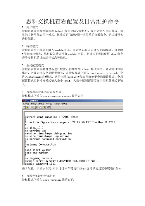
4.查看思科设备当前运行配置特权模式下输入show running-config显示如下:由于配置一页显示不完,可以通过回车键逐行显示,也可以通过空格键逐页显示。
5.查看设备软件版本信息特权模式下输入show version显示如下:此命令用于显示设备型号、序列号、系统版本和在线时间等等信息。
6.查看系统时钟特权模式下输入show clock用于显示当前系统时钟,可以用于查看LOG日志后对应时钟分析异常LOG的发起时间。
7.查看LOG日志特权模式下输入show log用于显示系统突发状况,例如端口异常关闭,链路的通断,主备机切换等等许多信息,可以帮助管理员分析故障原因。
8.查看端口详细状态特权模式下输入show interface显示如下:此命令用于显示端口的详细信息,例如IP地址、MAC地址、带宽负载及输入输出速率等。
9.快速查看端口UP or DOWN特权模式下输入show interface description和show interface status第一条命令查看端口的连接状态与描述,第二条命令查看端口的链接状态、所属vlan以及速率双工。
VSS(虚拟交换系统)配置手册
Active
Standby
虚拟交换链路(VSL)
多设备Etherchannel
一个Etherchannel是一个能把两个以上物理链路捆绑在一起形成一个逻 辑链路的技。二层协议的运作在Etherchannel上如同在一个单独链路 上一样。
多设备Etherchannel(MEC)是一种能把物理链路同时分布与VSS系统中 的两个设备上的Etherchannel技术。VSS下联设备看待MEC如同一个标 准的Etherchannel链路。 VSS最大支持128个Etherchannel。这个限制包括Etherchannel和MEC。 由于VSL需要两个Etherchannel号,所以能使用的Etherchannel只有126 个。
虚拟交换系统(VSS)将两台Cisco Catalyst 6500系列交换 机组合为单一虚拟交换机,对外来看,它管理冗余链路如同 管理自己的一个单一接口。 虚拟交换系统通过减少3层路由邻居和2层无环的拓扑,简化了 网络的配置和操作。
虚拟交换系统
虚拟交换系统将两台交换机结合成单一的交换机。
虚拟交换系统
VSS系统初始化
虚拟交换链路协议(VSLP)由状态决定协议(RRP)和链路管理协议(LMP)共同组成,并对 VSS系统的初始化起到一定作用。 当2台设备和他们之间的VSL链路正常工作后,一个VSS系统就形成了。2台设备通过 VSL相互协商所属状态。当系统安全初始化完成前VSL将正常工作。初始化分以下几 步:
思科交换产品
Cisco Catalyst 6500系列交换机虚拟 交换系统(VSS)
前言
网络管理员在考虑网络可靠性的时候,通常都是用冗余链路来配置连接交换 机。冗余的网络链路增加了网络的设计性和可操作性。
6500系列交换机升级指导说明书

6500系列交换机升级指导说明书一、6500系列交换机待升级的版本6503版本号:S6503-VRP3.10-0033BootRom版本:主控板升级为305(含)以上,业务板BootRom不用升级;6506版本号:S6506-VRP3.10-0033BootRom版本:主控板升级为305(含)以上,业务板BootRom不用升级;6506R版本号:S6506R-VRP3.10-0033BootRom版本:主控板升级为305(含)以上,业务板BootRom不用升级;二、该版本解决问题列表1.6503-033版本解决问题列表修改011版本DEV任务挂死问题。
判断方法:用display task命令查看任务如果DEV任务显示为ready表明挂死,正常情况下应该是Event Sem状态;。
修改011版本配置网管口导致CPU占用率高问题。
修改011版本重新建三层接口会将IP redirect报文上CPU错误打开问题。
通过debug rxtx evt 命令可以观察上CPU报文的类型和流量;修改012版本内存泄漏问题。
修改012(含)以前版本IPX报文二层无法透传问题。
修改013版本监控机制恢复RDRAM和2204引起硬件故障放大的问题。
修改016版本29、30、32等价路由引起Ping丢包问题。
修改016(含)以前版本5分钟速率不准问题。
修改016(含)以前版本端口速率大于64K,不恢复芯片引起端口不发送报文的问题。
修改016版本,在大路由表和ARP变化比较大的情况下删除三层接口,引起重起问题。
修改016(含)以前版本配置端口镜像,使得重启时CFM任务挂死,无法启动的问题。
修改016(含)以前版本交换机遭到TCN攻击反复删除ARP,MAC地址表导致网络严重丢包的问题。
修改016(含)以前版本不支持端口双向CAR问题,以前版本只支持端口出带宽限制,该版本可以同时支持端口入带宽限制和端口出带宽限制。
修改016(含)以前版本配置多条端口镜像,Display Current导致交换机重启的问题。
cisco 6500系列配置
老式65是存在二个镜像的问题,直接进入时为Cat IOS,只能配置二层信息,如果要配置路由等,需利用session 15这个命令访问MSFC,也就是所谓的native ios。
新款65都是native ios,可直接做二层及三层的配置需求。
1,查看交换机基本配置show version ;查看系统版本,内存配置,寄存器等基本信息show module all ;查看交换机配置模块show catalyst6000 chassis-mac-address ;查看交换机MAC地址2,配置机器名、telnet、密码在全局模式下,用conf t,进入配置模式,进行以下配置:#conf t#clock timezone GMT 8 ;配置时区#clock set 13:30:21 31 JAN 2004 ;配置交换机时间#clock calendar-valid ;使能硬件时钟同步#service timestamps debug datetime localtime ;配置系统debug记录时间格式#service timestamps log datetime localtime ;配置系统日志记录时间格式#service password-encryption ;配置使用加密服务,主要针对口令加密#hostname xxxx ;配置交换机名称#enable secret 0 xxxxx ;配置enable口令#copy run start ;将配置信息保存到NVRAM中,重启动不会丢失#line vty 0 4 ;配置telnet#exec-timeout 30 0#password 0 xxxx#login3,配置snmp#conf t#snmp-server community cisco ro(只读);配置只读通信字符串#snmp-server community secret rw(读写);配置读写通信字符串#snmp-server enable traps ;配置网关SNMP TRAP#snmp-server host 10.254.190.1 rw ;配置网关工作站地址4,查看和配置系统环境变量使用show bootvar命令查看系统启动环境变量,包括BOOT, BOOTLDR, andCONFIG_FILE参数:Router# show bootvarBOOT variable = slot0:c6sup22-jsv-mz.121-5c.EX.bin,1;CONFIG_FILE variable does not existBOOTLDR variable = bootflash:c6msfc2-boot-mz.121-3a.E4Configuration register is 0x2Router#改变BOOT,、BOOTLDR、CONFIG_FILE 这三个环境变量使用命令:BOOT #boot systemBOOTLDR #boot bootldrCONFIG_FILE #boot config端口设置5,端口基本设置Cisco 65xx系列交换机的端口缺省都是路由模式,一般都会配置为交换端口使用,进入端口配置模式:对于单一端口,在配置模式下输入:interface Ethernet,Fast Ethernet,GigabitEthernet x/y, x为槽位号,y为端口号。
6500交换机简单命令手册

6000交换机配置维护手册(Native IOS)目录1. 连接设备 (3)1.1.从CONSOLE连接 (3)1.2.远程TELNET连接 (5)2. 基本信息配置 (5)2.1.配置机器名、TELNET、密码 (5)2.2.配置SNMP网管串 (5)3. 冗余及系统高可用性配置 (6)3.1.同步S UPERVISOR E NGINE配置 (6)3.2.查看S UPERVISOR E NGINE冗余 (7)3.3.向冗余S UPERVISOR E NGINE拷贝IOS文件 (8)4. 端口设置 (9)4.1.基本设置 (9)4.2.配置三层端口 (10)5. 配置二层端口 (10)5.1.配置T RUNK: (10)6. 配置HSRP (11)6.1.配置二层普通交换接口 (12)6.2.清除二层接口配置 (12)7. 配置VLAN (12)8. 动态路由协议--OSPF配置 (13)8.1.启用OSPF动态路由协议 (14)8.2.定义参与OSPF的子网 (14)8.3.OSPF区域间的路由信息汇总 (14)8.4.配置密码验证 (15)8.5.设置产生缺省路由 (15)9. 交换机维护 (16)9.1.交换机IOS保存和升级 (16)9.2.交换机密码恢复 (16)1. 连接设备1.1. 从console连接第一次对6000交换机进行配置,必须从console进入。
首先先将机器上架,按要求接好电源,然后用随机附带的Console线和转接头将交换机的console口与PC的串口相联,如下:Com口设置如下:∙9600 baud∙8 data bits∙No parity∙ 2 stop bits检查电源无误后,开电,可能会出现类似下面的显示,按黑粗体字回答:System Bootstrap, Version 6.1(2)Copyright (c) 1994-2000 by cisco Systems, Inc.c6k_sup2 processor with 131072 Kbytes of main memoryrommon 1 > boot slot0:c6sup22-jsv-mz.121-5c.EX.binSelf decompressing the image : ################################################################################################################################ ############################################################################### ############################################################################### ############################################################################### [OK]Restricted Rights LegendUse, duplication, or disclosure by the Government issubject to restrictions as set forth in subparagraph(c) of the Commercial Computer Software - RestrictedRights clause at FAR sec. 52.227-19 and subparagraph(c) (1) (ii) of the Rights in Technical Data and ComputerSoftware clause at DFARS sec. 252.227-7013.cisco Systems, Inc.170 West Tasman DriveSan Jose, California 95134-1706Cisco Internetwork Operating System SoftwareIOS (tm) MSFC2 Software (C6MSFC2-BOOT-M), Version 12.1(3a)E4, EARLY DEPLOYMENT R ELEASE SOFTWARE (fc1)Copyright (c) 1986-2000 by cisco Systems, Inc.Compiled Sat 14-Oct-00 05:33 by eaarmasImage text-base: 0x30008980, data-base: 0x303B6000cisco Cat6k-MSFC2 (R7000) processor with 114688K/16384K bytes of memory.Processor board ID SAD04430J9KR7000 CPU at 300Mhz, Implementation 39, Rev 2.1, 256KB L2, 1024KB L3 CacheLast reset from power-onX.25 software, Version 3.0.0.509K bytes of non-volatile configuration memory.16384K bytes of Flash internal SIMM (Sector size 512K).Press RETURN to get started!--- System Configuration Dialog ---Would you like to enter the initial dialog? [yes]: no回答:NO,进入手工配置,在router>下,输入enable回车,进入全局模式1.2. 远程telnet连接当完成交换机配置,并起给交换机配置了管理地址,就可以直接采用远程telnet 登陆进入交换机了,但是必须先配置line vty的密码和enable密码才能允许远程登陆。
维护操作手册(Cisco设备)

DCN网思科网络设备操作维护手册(版本号:V2.0)中国移动江苏公司联创科技(南京)有限公司文档编号:文档日期:2007年9月18日文档信息文档变更记录审核批准版权说明本文件中出现的任何文字叙述、文件格式、插图、照片、方法等内容,除另有特别注明,版权均属江苏移动通信有限责任公司和南京联创科技股份有限公司所有,受到有关产权及版权法保护。
任何个人、机构未经江苏移动通信有限责任公司和南京联创科技股份有限公司的书面授权许可,不得复制或引用本文件的任何片断,无论通过电子形式或非电子形式。
目录1. 路由器配置基础 (9)1.1. 基本配置方式 (9)1.2. 命令状态 (10)1.3. 设置对话过程 (10)1.4. 常用命令 (13)1.5. 配置IP地址 (14)1.6. 配置静态路由 (17)2. 广域网协议设置 (18)2.1. HDLC (18)2.1.1. 相关命令 (18)2.1.2. 举例 (19)2.1.3. 举例使用EI线路实现多个64K专线连接. (19)2.2. PPP (21)2.3. X.25 (23)2.4. Frame Relay (27)2.5. ISDN (31)2.6. PSTN (40)3. 路由配置协议 (54)3.1. RIP协议 (54)3.2. IGRP协议 (56)3.3. OSPF协议 (57)3.4. 重新分配路由 (62)3.5. IPX协议设置 (64)4. 服务质量及访问控制 (66)4.1. 协议优先级设置 (66)4.2. 队列定制 (67)4.3. 访问控制 (68)5. 虚拟局域网(VLAN)路由 (69)5.1. 虚拟局域网 (69)5.2. 交换机间(ISL)协议 (69)5.3. 虚拟局域网(VLAN)路由实例 (70)6. PPPoE配置 (76)7. 路由器安全配置 (77)7.1. 访问列表 (77)7.1.1. 标准IP访问列表 (78)7.1.2. 扩展IP访问列表 (79)7.1.3. 管理和使用访问表 (80)7.2. 密码管理 (82)7.2.1. 登录口令管理 (82)7.2.2. 特权口令管理 (82)7.3. 控制线路访问 (83)7.3.1. 限制对VTY端口的访问 (83)7.3.2. 限制用户能够连接的地址 (83)7.3.3. 控制用户能够使用的命令 (83)7.4. CDP (83)7.5. HTTP配置服务 (84)7.6. 其他推荐缺省配置 (84)7.6.1. 拒绝RFC1918路由 (84)7.6.2. UDP和TCP服务器 (86)7.6.3. Finger服务 (86)7.6.4. IP Unreachable报文 (86)7.6.5. IP Redirect报文 (87)7.6.6. 定向广播 (87)7.6.7. Proxy Arp (87)7.6.8. Ip Verify (88)7.6.9. IP源路由 (88)7.7. TCP截获 (88)8. SNMP (90)8.1. SNMP的来源 (90)8.2. SNMP操作原理 (91)8.3. IOS中的SNMP配置 (92)9. DPT环的配置和管理 (93)10. 参考 (101)10.1. Cisco路由器口令恢复 (101)10.2. IP地址分配 (102)10.3. 做线线序 (102)1.路由器配置基础1.1. 基本配置方式一般来说,可以用5种方式来设置路由器:2.通过AUX口接MODEM,通过电话线与远方的终端或运行终端仿真软件的微机相连;3.通过Ethernet上的TFTP服务器;4.通过Ethernet 上的TELNET程序;5.通过Ethernet 上的SNMP网管工作站。
6500系列交换机手册
CATALYST 6500系列Supervisor Engine简明手册CATALYST 6500系列Supervisor Engine简明手册一.Supervisor Engine的介绍:CATALYST 6500系列交换机上的Supervisor Engine分为SupervisorEngine 1/2/32/720四种.Supervisor Engine 1又分:1.WS-X6K-SUP1-2GE:包含双1000BASE-X GBIC uplink口.QoS端口体系结构(Rx/Tx):1q4t/2q2t.2.WS-X6K-SUP1A-2GE:包含双1000BASE-X GBIC uplink口.QoS端口体系结构(Rx/Tx):1p1q4t/1p2q2t.3.WS-X6K-S1A-MSFC2:包含双1000BASE-X GBIC uplink口,PFC和MSFC2卡.QoS端口体系结构(Rx/Tx):1p1q4t/1p2q2t.4.WS-X6K-SUP1A-MSFC:包含双1000BASE-X GBIC uplink口,PFC和MSFC卡.QoS端口体系结构(Rx/Tx):1p1q4t/1p2q2t.5.WS-XSUP1A-PFC:包含双1000BASE-X GBIC uplink口以及PFC卡.QoS端口体系结构(Rx/Tx):1p1q4t/1p2q2t.注:CATALYST 6513不支持Supervisor Engine 1.Supervisor Engine 2又分:1.WS-X6K-S2-MSFC2:包含双1000BASE-X GBIC uplink口,矩阵特性,支持PFC2和MSFC2卡,在Supervisor Engine 2和MSFC2卡上各支持128M存储空间.QoS端口体系结构(Rx/Tx):1p1q4t/1p2q2t.2.WS-X6K-S2U-MSFC2:包含双1000BASE-X GBIC uplink口,矩阵特性,支持PFC2和MSFC2卡,在Supervisor Engine 2和MSFC2卡上各支持256M存储空间.QoS端口体系结构(Rx/Tx):1p1q4t/1p2q2t.3.WS-X6K-S2-PFC2:包含双1000BASE-X GBIC uplink口,矩阵特性,支持PFC2卡.QoS端口体系结构(Rx/Tx):1p1q4t/1p2q2t. Supervisor Engine 32又分:1.WS-SUP32-GE-3B:包括9个GE uplink口(其中8个为SFP接口另1个为10/100/1000Mbps RJ-45接口),MSFC2卡.QoS端口体系结构(Rx/Tx):2q8t/1p3q8t.2.WS-SUP32-10GE-3B:包含2个GE口,1个10/100/1000Mbps端口,FPC3B和MSFC2卡.QoS端口体系结构(Rx/Tx):2q8t/1p3q8t.Supervisor Engine 720包含:1.2个以太网uplink口(其中端口1支持SFP模块;端口2支持千兆SFP 或10/100/1000Mbps RJ-45接口),FPC3A卡,以及bootflash为64M,DRAM为512M的MSFC3卡.2.集成720Gbps的交换矩阵.3.2个CompactFlash Type II插槽(DISK 0/1).4.在6/9槽机箱必须插在5号或6号插槽;在13插槽机箱必须插在7号或8号插槽.要求安装高速风扇托盘.5.QoS端口体系结构(Rx/Tx):1p1q4t/1p2q2t.各个组件的介绍:1.RESET按键:用于重启交换机.2.CONSOLE口:用于本地或通过modem远程配置交换机.3.Switch Load(交换机负载):用于直观查看背板流量.4.PCMCIA插槽:额外的flash存储卡插槽,可用于保存软件镜象.5.uplink口以及USB 2.0口(只在Supervisor Engine 32上有).6.LED.各种LED颜色含义:1.STATUS LED:绿:诊断测试通过,运转正常.橘黄:模块刚启动或正在诊断测试中;模块温度过热.红:诊断测试失败;模块温度过热.2.SYSTEM LED:绿:所有环境监测状态正常.橘黄:供电失败或风扇故障;电源不兼容;VTT(电压终止)模块故障或温度过热.红:VTT(电压终止)模块故障或温度过;Supervisor Engine模块温度过热.3.ACTIVE LED:绿:运转正常并且为主模块.橘黄:Supervisor Engine模块处于备用(standby)状态.4.PWR MGMT LED:绿:所有模块电量充足.橘黄:模块电量不足.5.LINK LED:绿:端口正常.橘黄:交换机软件化的禁用该端口.闪烁橘黄:链路故障或硬件问题.熄灭:未检测到信号.二.CATALYST 6000/6500系列交换机的介绍:CATALYST 6000系列交换机支持Supervisor Engine 1/2(不支持Supervisor Engine 720),背板带宽高达32Gbps.CATALYST 6000系列交换机分为两种:1.6插槽(6006).2.9插槽(6009).CATALYST 6500系列交换机分以下几种:1.3插槽(6503).2.6插槽(6506).3.9插槽(6509).4.垂直结构的9插槽(6509-NEB).5.垂直结构的9插槽(6509-NEB-A).6.13插槽(6513).其中6503背板带宽上限为32Gbps,其余几款可扩展到256Gbps.CATALYST 6000/6500系列交换机支持双Supervisor Engine(必须一致),并可以采用以下几种搭配方式:1.不带PFC和MSFC卡的双Supervisor Engine.2.带PFC卡的双Supervisor Engine.3.带PFC和MSFC卡的双Supervisor Engine.注:6513不支持Supervisor Engine 1.CATALYST 6500系列交换机除支持相应的Supervisor Engine和交换模块等,还支持交换矩阵模块(WS-C6500-SFM/WS-X6500-SFM2).但要注意的是:1.只有Supervisor Engine 2支持交换矩阵模块;Supervisor Engine 720不支持.2.WS-C6500-SFM/WS-X6500-SFM2模块可安装于6插槽机箱(如6506/6509)的5号插槽,备用模块可插在第6号插槽.3.只有WS-X6500-SFM2模块能安装在6513的7号插槽,备用模块可以插在8号插槽.注:WS-C6500-SFM/WS-X6500-SFM2模块可以组合使用.谁先被安装,谁就做为主模块;如果同时安装,那么5/7号插槽的模块为主模块,6/8号的模块为备用模块.如果此时把5/7号插槽的模块重启,那么6/8号插槽的模块将做为主模块.CATALYST 6500系列交换机的存储组件:1.512K的NVRAM用于存储配置文件.2.Supervisor Engine上的EEPROM组件用于存储特定模块信息,如模块序列号,硬件修正号等.3.Supervisor Engine 1/2用于存储默认系统软件的DRAM大小为128M;Supervisor Engine 2U为256M;Supervisor Engine 720为512M.用于存储软件镜象的flash大小,Supervisor Engine 1为16M;Supervisor Engine 2为32M;Supervisor Engine 720为64M.4.flash文件系统(bootflash和PCMCIA卡).注:Supervisor Engine 1和2支持不同的PCMCIA卡,因此在使用前先格式化.CATALYST 6500系列交换机物理接口编址方式:插槽号/端口号(slot/port).模块插槽的自上而下进行编号,从1开始;端口号从左向右编号,也是从1开始.如下图:Supervisor Engine的热插拔(hot swapping):可以在不关闭电源的情况下插拔备用Supervisor Engine(即热交换,或热插拔).当热插拔备用Supervisor Engine模块的时候:1.交换机先确定该模块是否有充足电量可用.2.进行背板扫描,修改配置.3.初始化新插入的模块,或把移除的模块标记为管理性关闭(administratively down)的状态.4.将之前配置好的接口还原为移除模块后的配置;新增接口处于管理性关闭状态.交换机将对新增模块上的接口进行诊断测试,如果测试通过,交换机将继续正常工作.如果Supervisor Engine有故障,交换机正常运转的同时,将该模块处于禁用状态;如果诊断测试未通过,交换机将报错.本地化配置交换机可以通过CONSOLE口进行配置,PC超级终端的设置如下:。
CISCO交换机常用维护手册
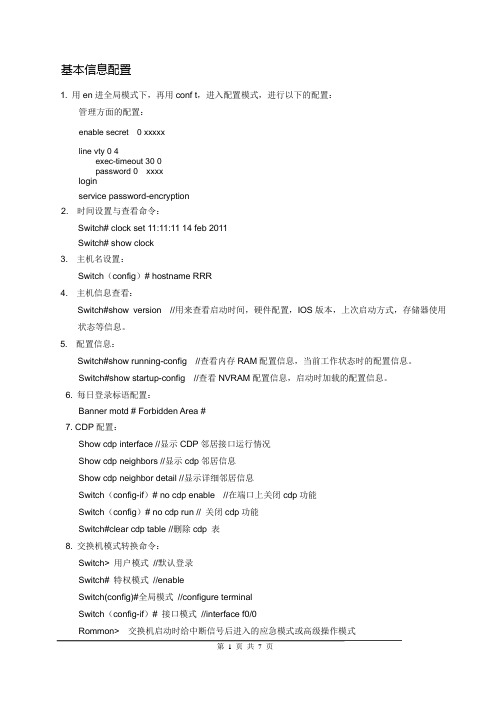
基本信息配置1. 用en进全局模式下,再用conf t,进入配置模式,进行以下的配置:管理方面的配置:enable secret 0 xxxxxline vty 0 4exec-timeout 30 0password 0 xxxxloginservice password-encryption2. 时间设置与查看命令:Switch# clock set 11:11:11 14 feb 2011Switch# show clock3. 主机名设置:Switch(config)# hostname RRR4. 主机信息查看:Switch#show version //用来查看启动时间,硬件配置,IOS版本,上次启动方式,存储器使用状态等信息。
5. 配置信息:Switch#show running-config //查看内存RAM配置信息,当前工作状态时的配置信息。
Switch#show startup-config //查看NVRAM配置信息,启动时加载的配置信息。
6. 每日登录标语配置:Banner motd # Forbidden Area #7. CDP配置:Show cdp interface //显示CDP邻居接口运行情况Show cdp neighbors //显示cdp邻居信息Show cdp neighbor detail //显示详细邻居信息Switch(config-if)# no cdp enable //在端口上关闭cdp功能Switch(config)# no cdp run // 关闭cdp功能Switch#clear cdp table //删除cdp 表8. 交换机模式转换命令:Switch> 用户模式//默认登录Switch# 特权模式//enableSwitch(config)#全局模式//configure terminalSwitch(config-if)# 接口模式//interface f0/0Rommon> 交换机启动时给中断信号后进入的应急模式或高级操作模式9. 启用三层交换功能Switch(config)#ip routing10 设置vlan nSwitch(config)#vlan 2Switch(config-vlan)#name vlan 2Switch(config)#exitSwitch(config-if)# switch mode accessSwitch(config-if)# switch mode access vlan 211 配置etherchannelSwitch(config)int port-channel 1 //建立捆绑口Switch(config)int range fa0/1-2 //Switch(config-if)channel-group 1 mode on // 将端口归属到捆绑口上Switch(config-if)switchport mode trunk enc dot1q // 定义TRUNK封装Switch(config-if)switchport mode trunk //Switch(config)port-channel load-balance dst-ip //定义负载方式检验命令:show etherchannel summary1配置接口速率和双工Switch(config-if)#speed [10 | 100 | auto](速度)Switch(config-if)# duplex [auto | full | half](双工)Switch(config-if)#des 描述字Switch(config-if)#shutdown 关闭接口Switch(config-if)#no sh 开启接口2 配置三层接口Switch(config-if)# ip add ip mask3 配置trunk接口Switch(config)# interface fastethernet x/y (以fastethernet为例,gigabitethernet一样)Switch(config-if)# shutdownSwitch(config-if)# switchportSwitch(config-if)# switchport mode dynamic desirable|trunk|autoSwitch(config-if)# switchport trunk encapsulation dot1qSwitch(config-if)# switchport trunk allowed vlan 2-3Switch(config-if)# no shutdownSwitch(config-if)# endSwitch# exit4端口划分vlanSwitch(config-if)# switch mode accessSwitch(config-if)# switch mode access vlan 25常用端口查看命令Switch# show int fa0/0Switch# show controllers s0/0Switch# show ip interface fa0/0Switch# show ip int briefSwitch# show vlan all //查看vlan信息Switch#show int trunk //查看trunk 端口6.修改NATIVE VLANSwitch(config-if)# switchport trunk native vlan 107.交换机端口安全Switch(config-if)# switch port-securitiySwitch(config-if)# switch port-securitiy maximum 1 //设置端口绑定mac地址数量Switch(config-if)# switch port-securitiy violation shutdown|protect|restrict //设置违规保护方式1. 配置HSRP在其中一台4507上按下面模版进行配置interface Vlan x //可选ip address 本机端口ip maskstandby 1 虚拟ipstandby 1 preemptstandby 1 priority 100可选standby 1 authentication 字符串Standby 1 时间参数1 时间参数2 // hello时间间隔1 失效时间间隔2Standby 1 track portnumber//没有实际意义在另一台4507上按下面模版进行配置interface Vlan x //可选ip address 本机端口ip maskstandby 1 虚拟ipstandby 1 preemptstandby 1 priority 100可选standby 1 authentication 字符串Standby 1 时间参数1 时间参数2 // hello时间间隔1 失效时间间隔2Standby 1 track portnumber//没有实际意义2. 基于策略的限速(QOS)配置1. Switch(config)# mls qos2. Access-list 12 permit 1.1.1.2 0.0.0.255 //用访问控制列表定义流量3. Switch(config)# class-map nameSwitch(config-cmap)# access-group 124. Switch(config)# policy-map nameSwitch(config-pmap)#class nameSwitch(config-pmap)#trust dscpSwitch(config-pmap)#police 1024000 1024000 exceed-action drop5. Switch(config-if)#service-policy input name日常维护及故障处理1. 常用系统检查命令:sh proc cpu // 检查cpu使用情况sh flash: //检查flash 内容sh mem //检查ram使用情况sh buffer //查看动态缓存利用状况sh env all //检查风扇,温度,电源状态sh module //检查机器板卡模块sh redundancy status // 检查冗余备引擎状态sh redundancy history //检查冗余主备引擎之间的状态sh redundancy switchover //检查系统状态sh log //检查系统日志sh runsh startup-config2. 系统配置备份命令:wr //配置保存命令copy run startup //同wrcopy flash: ios tftp: //备份ioscopy run tftp // 备份running-config3. 全面系统信息查看命令Show tech-support //全部系统状态信息的批处理显示建议利用secure-crt软件将其定期拷贝出来。
cisco6500双机实际配置(ios)

Cisco 6509配置如下:!! Last configuration change at 09:06:48 BEIJING Sun Oct 22 2006 ! NVRAM config last updated at 09:12:26 BEIJING Sun Oct 22 2006 !version 12.2service timestamps debug uptimeservice timestamps log uptimeservice password-encryptionservice counters max age 10!hostname Dual6509!boot system flash disk1:s72033-psv-mz.122-18.SXD7.binlogging buffered 16384 debuggingenable secret 5 $1$2O.e$9CBW1V.DhrfjSFkR8m4hh0enable password 7 14353D243F2705660C01070F06!no aaa new-modelclock timezone BEIJING 8ip subnet-zero!!no ip domain-lookup!mls ip multicast flow-stat-timer 9no mls flow ipno mls flow ipv6mls cef error action freeze!spanning-tree mode rapid-pvstno spanning-tree optimize bpdu transmissiondiagnostic cns publish s.device.diag_resultsdiagnostic cns subscribe s.device.diag_commands!redundancymode ssomain-cpuauto-sync running-config!vlan internal allocation policy ascendingvlan access-log ratelimit 2000!!interface Port-channel1no ip addressswitchportswitchport trunk encapsulation dot1q switchport mode trunk!interface GigabitEthernet5/1no ip addressshutdown!interface GigabitEthernet5/2no ip addressmedia-type rj45switchport!interface GigabitEthernet7/1no ip addressswitchportswitchport access vlan 10switchport mode accessspanning-tree portfast!interface GigabitEthernet7/2no ip addressswitchportswitchport access vlan 10spanning-tree portfast!interface GigabitEthernet7/3no ip addressswitchportswitchport access vlan 10spanning-tree portfast!interface GigabitEthernet7/4no ip addressswitchportswitchport access vlan 10spanning-tree portfast!interface GigabitEthernet7/5no ip addressswitchportswitchport access vlan 10spanning-tree portfast!interface GigabitEthernet7/6no ip addressswitchportswitchport access vlan 10spanning-tree portfast!interface GigabitEthernet7/7no ip addressswitchportswitchport access vlan 10spanning-tree portfast!interface GigabitEthernet7/8no ip addressswitchportswitchport access vlan 10spanning-tree portfast!interface GigabitEthernet7/9description connect 2610XM F0/0no ip addressswitchportswitchport access vlan 20spanning-tree portfast!interface GigabitEthernet7/10no ip addressswitchportswitchport access vlan 30spanning-tree portfast!interface GigabitEthernet7/11no ip addressswitchportswitchport trunk encapsulation dot1q switchport mode trunk!interface GigabitEthernet7/12no ip addressswitchportswitchport access vlan 40spanning-tree portfast!interface GigabitEthernet7/13no ip addressswitchportswitchport access vlan 40spanning-tree portfast!interface GigabitEthernet7/14no ip addressswitchportswitchport access vlan 40spanning-tree portfast!interface GigabitEthernet7/15no ip addressswitchportswitchport access vlan 40spanning-tree portfast!interface GigabitEthernet7/16no ip addressswitchportswitchport access vlan 40spanning-tree portfast!interface GigabitEthernet7/17no ip addressswitchportswitchport access vlan 40spanning-tree portfast!interface GigabitEthernet7/18description It is a test by hehero! no ip addressswitchportswitchport access vlan 40spanning-tree portfast!interface GigabitEthernet7/19no ip addressswitchportswitchport access vlan 40spanning-tree portfast!interface GigabitEthernet7/20 no ip addressswitchportswitchport access vlan 40spanning-tree portfast!interface GigabitEthernet7/21 no ip addressswitchportswitchport access vlan 40spanning-tree portfast!interface GigabitEthernet7/22 no ip addressswitchportswitchport access vlan 40spanning-tree portfast!interface GigabitEthernet7/23 no ip addressswitchportswitchport access vlan 40switchport mode accessspanning-tree portfast!interface GigabitEthernet7/24 no ip addressswitchportswitchport access vlan 40switchport mode accessspanning-tree portfast!interface GigabitEthernet7/25 no ip addressswitchportswitchport access vlan 40switchport mode accessspanning-tree portfast!interface GigabitEthernet7/26 no ip addressswitchportswitchport access vlan 40switchport mode accessspanning-tree portfast!interface GigabitEthernet7/27 no ip addressswitchportswitchport access vlan 40switchport mode accessspanning-tree portfast!interface GigabitEthernet7/28 no ip addressswitchportswitchport access vlan 40switchport mode accessspanning-tree portfast!interface GigabitEthernet7/29 no ip addressswitchportswitchport access vlan 40switchport mode accessspanning-tree portfast!interface GigabitEthernet7/30 no ip addressswitchportswitchport access vlan 60spanning-tree portfast!interface GigabitEthernet7/31 no ip addressswitchportswitchport access vlan 40switchport mode accessspanning-tree portfast!interface GigabitEthernet7/32 no ip addressshutdown!interface GigabitEthernet7/33 no ip addressshutdown!interface GigabitEthernet7/34no ip addressswitchport!interface GigabitEthernet7/35description connect Dual6506 G1/35no ip addressspeed 1000duplex fullswitchportswitchport trunk encapsulation dot1qswitchport mode trunkchannel-group 1 mode on!interface GigabitEthernet7/36description connect Dual6506 G1/36no ip addressspeed 1000duplex fullswitchportswitchport trunk encapsulation dot1qswitchport mode trunkchannel-group 1 mode on!interface GigabitEthernet7/37description connect XXZX-2960-24TT G0/1 no ip addressswitchportswitchport trunk encapsulation dot1qswitchport mode trunk!interface GigabitEthernet7/38no ip addressswitchportswitchport trunk encapsulation dot1qswitchport mode trunk!interface GigabitEthernet7/39no ip addressshutdown!interface GigabitEthernet7/40no ip addressswitchportswitchport access vlan 990 spanning-tree portfast!interface GigabitEthernet7/41 no ip addressspeed 1000duplex fullswitchportswitchport access vlan 10switchport mode accessspanning-tree portfast!interface GigabitEthernet7/42 no ip addressspeed 1000duplex fullswitchportswitchport access vlan 10switchport mode accessspanning-tree portfast!interface GigabitEthernet7/43 no ip addressspeed 1000duplex fullswitchportswitchport access vlan 10switchport mode accessspanning-tree portfast!interface GigabitEthernet7/44 no ip addressspeed 1000duplex fullswitchportswitchport access vlan 10switchport mode accessspanning-tree portfast!interface GigabitEthernet7/45 no ip addressspeed 1000duplex fullswitchportswitchport access vlan 10switchport mode accessspanning-tree portfast!interface GigabitEthernet7/46no ip addressspeed 1000duplex fullswitchportswitchport access vlan 10switchport mode accessspanning-tree portfast!interface GigabitEthernet7/47no ip addressswitchportswitchport access vlan 36switchport trunk encapsulation dot1qswitchport mode accessspanning-tree portfast!interface GigabitEthernet7/48no ip addressswitchportswitchport trunk encapsulation dot1qswitchport mode trunk!interface GigabitEthernet9/1description connect ZBGL-N-2970G-24 G0/25 no ip addressswitchportswitchport trunk encapsulation dot1qswitchport mode trunk!interface GigabitEthernet9/2description connect ZBGL-B-2970G-24 G0/25 no ip addressswitchportswitchport trunk encapsulation dot1qswitchport mode trunk!interface GigabitEthernet9/3description connect XSL-2970G-24 G0/25 no ip addressswitchportswitchport trunk encapsulation dot1qswitchport mode trunk!interface GigabitEthernet9/4description connect 1LG-2950G-48 G0/1no ip addressswitchportswitchport trunk encapsulation dot1qswitchport mode trunk!interface GigabitEthernet9/5description connect 2LG-2950G-24 G0/1no ip addressswitchportswitchport trunk encapsulation dot1qswitchport mode trunk!interface GigabitEthernet9/6description connect DGBGL-2960G-24 G0/21 no ip addressswitchportswitchport trunk encapsulation dot1qswitchport mode trunk!interface GigabitEthernet9/7description connect JSZX-3560G-48 G0/49 no ip addressswitchportswitchport trunk encapsulation dot1qswitchport mode trunk!interface GigabitEthernet9/8description connect LBZG-2960G-24 G0/1 no ip addressswitchportswitchport trunk encapsulation dot1qswitchport mode trunk!interface GigabitEthernet9/9description conn ZLGS-2960-24TC g0/1no ip addressswitchportswitchport trunk encapsulation dot1qswitchport mode trunk!interface GigabitEthernet9/10description connect DLFC-2960-24TC g0/1 no ip addressswitchportswitchport trunk encapsulation dot1qswitchport mode trunk!interface GigabitEthernet9/11description connect ZXGS-2960-48TC G0/1 no ip addressswitchportswitchport trunk encapsulation dot1qswitchport mode trunk!interface GigabitEthernet9/12description connect WBB-2960-48TC G0/1 no ip addressswitchportswitchport trunk encapsulation dot1qswitchport mode trunk!interface GigabitEthernet9/13description connect 50WD-3560-48 G0/1 no ip addressswitchportswitchport trunk encapsulation dot1qswitchport mode trunk!interface GigabitEthernet9/14no ip addressswitchportswitchport trunk encapsulation dot1qswitchport mode trunk!interface GigabitEthernet9/15no ip addressswitchportswitchport trunk encapsulation dot1qswitchport mode trunk!interface GigabitEthernet9/16no ip addressswitchportswitchport trunk encapsulation dot1q switchport mode trunk!interface GigabitEthernet9/17no ip addressswitchportswitchport trunk encapsulation dot1q switchport mode trunk!interface GigabitEthernet9/18no ip addressswitchportswitchport trunk encapsulation dot1q switchport mode trunk!interface GigabitEthernet9/19no ip addressswitchportswitchport trunk encapsulation dot1q switchport mode trunk!interface GigabitEthernet9/20no ip addressswitchportswitchport trunk encapsulation dot1q switchport mode trunk!interface GigabitEthernet9/21no ip addressswitchportswitchport trunk encapsulation dot1q switchport mode trunk!interface GigabitEthernet9/22no ip addressswitchportswitchport trunk encapsulation dot1q switchport mode trunk!interface GigabitEthernet9/23no ip addressswitchportswitchport trunk encapsulation dot1qswitchport mode trunk!interface GigabitEthernet9/24no ip addressswitchportswitchport trunk encapsulation dot1qswitchport mode trunk!interface Vlan1ip address 192.168.181.2 255.255.255.0 standby 1 ip 192.168.181.1standby 1 preempt!interface Vlan2no ip addressshutdown!interface Vlan10ip address 192.168.182.12 255.255.255.0 standby 1 ip 192.168.182.1standby 1 priority 110standby 1 preempt!interface Vlan20ip address 192.168.183.12 255.255.255.0 standby 1 ip 192.168.183.1standby 1 priority 110standby 1 preempt!interface Vlan22no ip addressshutdown!interface Vlan30ip address 192.168.184.2 255.255.255.0 standby 1 ip 192.168.184.254standby 1 priority 110standby 1 preempt!interface Vlan36ip address 192.168.36.2 255.255.255.0 standby 1 ip 192.168.36.1standby 1 priority 110standby 1 preempt!interface Vlan40ip address 192.168.185.2 255.255.255.0 standby 1 ip 192.168.185.1standby 1 priority 110standby 1 preempt!interface Vlan50ip address 192.168.186.2 255.255.255.0 standby 1 ip 192.168.186.1standby 1 priority 110standby 1 preempt!interface Vlan60ip address 192.168.187.2 255.255.255.0 standby 1 ip 192.168.187.1standby 1 priority 110standby 1 preempt!interface Vlan70ip address 192.168.188.2 255.255.255.0 standby 1 ip 192.168.188.1standby 1 priority 110standby 1 preempt!interface Vlan80ip address 192.168.189.2 255.255.255.0 standby 1 ip 192.168.189.1standby 1 priority 110standby 1 preempt!interface Vlan90ip address 192.168.190.2 255.255.255.0 standby 1 ip 192.168.190.1standby 1 priority 110standby 1 preempt!interface Vlan100ip address 192.168.191.2 255.255.255.0 standby 1 ip 192.168.191.1standby 1 priority 110standby 1 preempt!interface Vlan110ip address 192.168.192.2 255.255.255.0standby 1 ip 192.168.192.1standby 1 priority 110standby 1 preempt!interface Vlan120ip address 192.168.193.2 255.255.255.0standby 1 ip 192.168.193.1standby 1 priority 110standby 1 preempt!interface Vlan130ip address 192.168.194.2 255.255.255.128 standby 1 ip 192.168.194.1standby 1 priority 110standby 1 preempt!interface Vlan131ip address 192.168.194.252 255.255.255.128 standby 1 ip 192.168.194.129standby 1 priority 110standby 1 preempt!interface Vlan135ip address 192.168.195.2 255.255.255.0standby 1 ip 192.168.195.1standby 1 priority 110standby 1 preempt!interface Vlan140ip address 192.168.196.2 255.255.255.0standby 1 ip 192.168.196.1standby 1 priority 110standby 1 preempt!interface Vlan150ip address 192.168.197.2 255.255.255.0standby 1 ip 192.168.197.1standby 1 priority 110standby 1 preempt!interface Vlan160ip address 192.168.198.2 255.255.255.0 standby 1 ip 192.168.198.1standby 1 preempt!interface Vlan170ip address 192.168.199.4 255.255.255.0 shutdownstandby 1 ip 192.168.199.1standby 1 priority 110standby 1 preempt!interface Vlan180ip address 192.168.201.2 255.255.255.0 standby 1 ip 192.168.201.1standby 1 preempt!interface Vlan190ip address 192.168.202.2 255.255.255.0 standby 1 ip 192.168.202.1standby 1 preempt!interface Vlan200ip address 192.168.203.2 255.255.255.0 standby 1 ip 192.168.203.1standby 1 preempt!interface Vlan201ip address 192.168.204.2 255.255.255.0 standby 1 ip 192.168.204.1standby 1 preempt!interface Vlan202ip address 192.168.205.2 255.255.255.0 standby 1 ip 192.168.205.1standby 1 preempt!interface Vlan203ip address 192.168.206.2 255.255.255.0 standby 1 ip 192.168.206.1standby 1 preempt!interface Vlan204ip address 192.168.207.2 255.255.255.0 standby 1 ip 192.168.207.1standby 1 preempt!interface Vlan205ip address 192.168.208.2 255.255.255.0 standby 1 ip 192.168.208.1standby 1 preempt!interface Vlan206ip address 192.168.209.2 255.255.255.0 standby 1 ip 192.168.209.1standby 1 preempt!interface Vlan207ip address 192.168.210.2 255.255.255.0 standby 1 ip 192.168.210.1standby 1 preempt!interface Vlan208ip address 192.168.211.2 255.255.255.0 standby 1 ip 192.168.211.1standby 1 preempt!interface Vlan209ip address 192.168.212.2 255.255.255.0 standby 1 ip 192.168.212.1standby 1 preempt!interface Vlan210ip address 192.168.213.2 255.255.255.0 standby 1 ip 192.168.213.1standby 1 preempt!interface Vlan211ip address 192.168.214.2 255.255.255.0 standby 1 ip 192.168.214.1standby 1 preempt!interface Vlan212ip address 192.168.215.2 255.255.255.0 standby 1 ip 192.168.215.1standby 1 preempt!interface Vlan220ip address 192.168.220.2 255.255.255.0standby 1 ip 192.168.220.1standby 1 preempt!interface Vlan222ip address 192.168.222.2 255.255.255.0 standby 1 ip 192.168.222.1standby 1 preempt!interface Vlan990ip address 192.168.250.2 255.255.255.0 standby 1 ip 192.168.250.1standby 1 preempt!router ripversion 2network 192.168.36.0network 192.168.181.0network 192.168.182.0network 192.168.183.0network 192.168.184.0network 192.168.185.0network 192.168.186.0network 192.168.187.0network 192.168.188.0network 192.168.189.0network 192.168.190.0network 192.168.191.0network 192.168.192.0network 192.168.193.0network 192.168.194.0network 192.168.195.0network 192.168.196.0network 192.168.197.0network 192.168.198.0network 192.168.201.0network 192.168.202.0network 192.168.203.0network 192.168.204.0network 192.168.205.0network 192.168.206.0network 192.168.207.0network 192.168.208.0network 192.168.209.0network 192.168.210.0network 192.168.211.0network 192.168.212.0network 192.168.213.0network 192.168.214.0network 192.168.215.0network 192.168.220.0network 192.168.222.0network 192.168.250.0!ip default-gateway 192.168.181.1ip classlessip route 0.0.0.0 0.0.0.0 192.168.182.11ip route 172.18.0.0 255.255.0.0 192.168.184.139ip route 192.168.0.0 255.255.128.0 192.168.184.139ip route 192.168.10.0 255.255.255.0 192.168.36.254ip route 192.168.128.0 255.255.224.0 192.168.184.139ip route 192.168.160.0 255.255.240.0 192.168.184.139ip route 192.168.176.0 255.255.252.0 192.168.184.139ip route 192.168.200.0 255.255.255.0 192.168.184.139ip http server!!!logging history size 100logging 192.168.182.9arp 192.168.204.11 000a.e688.a437 ARPAarp 192.168.204.21 000a.e63c.fc37 ARPAarp 192.168.204.31 0016.1782.2437 ARPAarp 192.168.185.21 0011.857e.d45e ARPAarp 192.168.185.23 0011.857e.d475 ARPAarp 192.168.185.25 0011.857e.d485 ARPAarp 192.168.185.24 0011.857e.d384 ARPAarp 192.168.190.14 000f.fe13.90dc ARPAarp 192.168.186.15 000f.fe13.905d ARPAarp 192.168.187.62 000f.fe13.922c ARPAarp 192.168.197.91 000f.fe16.e726 ARPA!snmp-server community public ROsnmp-server community private RWsnmp-server packetsize 2048snmp-server enable traps snmp authentication linkdown linkup coldstart warmstart snmp-server enable traps chassissnmp-server enable traps modulesnmp-server enable traps ttysnmp-server enable traps casasnmp-server enable traps vtpsnmp-server enable traps vlancreatesnmp-server enable traps vlandeletesnmp-server enable traps slb real virtual csrpsnmp-server enable traps csg agent quota databasesnmp-server enable traps hsrpsnmp-server enable traps entitysnmp-server enable traps config-copysnmp-server enable traps fru-ctrlsnmp-server enable traps c6kxbar swbussnmp-server enable traps envmon fan shutdown supply temperature statussnmp-server enable traps bridge newroot topologychangesnmp-server enable traps stpxsnmp-server enable traps vlan-mac-limitsnmp-server enable traps flash insertion removalsnmp-server enable traps rfsnmp-server enable traps MAC-Notification move thresholdsnmp-server enable traps syslogsnmp-server enable traps bgpsnmp-server enable traps pim neighbor-change rp-mapping-change invalid-pim-message snmp-server enable traps ipmulticastsnmp-server enable traps msdpsnmp-server enable traps rsvpsnmp-server enable traps frame-relaysnmp-server enable traps rtrsnmp-server enable traps srpsnmp-server enable traps sonetsnmp-server enable traps mpls traffic-engsnmp-server enable traps mpls ldpsnmp-server enable traps dlswsnmp-server enable traps mpls vpnsnmp-server host 192.168.182.9 version 2c privatesnmp-server host 192.168.182.9 version 2c public!!control-plane!!!line con 0line vty 0 4password 7 070D325F4D06540D1E061108loginline vty 5 15password 7 094E5D1A1A0A5A1A02181E2Elogin!ntp master 3endcisco 6506配置如下:!! Last configuration change at 10:20:51 BEIJING Sun Oct 22 2006 ! NVRAM config last updated at 10:20:52 BEIJING Sun Oct 22 2006 !version 12.2service timestamps debug uptimeservice timestamps log uptimeservice password-encryptionservice internalservice counters max age 10!hostname Dual6506!boot system flash disk1:s72033-psv-mz.122-18.SXD7.binenable secret 5 $1$phuV$U7xfScp2MW6LcH.01WQjb/enable password 7 130704010803492222303237!no aaa new-modelclock timezone BEIJING 8ip subnet-zero!!no ip domain-lookup!mls ip multicast flow-stat-timer 9no mls flow ipno mls flow ipv6mls cef error action freeze!spanning-tree mode rapid-pvstno spanning-tree optimize bpdu transmissiondiagnostic cns publish s.device.diag_resultsdiagnostic cns subscribe s.device.diag_commands!redundancymode ssomain-cpuauto-sync running-config!vlan internal allocation policy ascending vlan access-log ratelimit 2000!!interface Port-channel1no ip addressswitchportswitchport trunk encapsulation dot1qswitchport mode trunk!interface GigabitEthernet1/1no ip addressswitchportswitchport access vlan 10spanning-tree portfast!interface GigabitEthernet1/2no ip addressswitchportswitchport access vlan 10spanning-tree portfast!interface GigabitEthernet1/3no ip addressswitchportswitchport access vlan 10spanning-tree portfast!interface GigabitEthernet1/4no ip addressswitchportswitchport access vlan 10spanning-tree portfast!interface GigabitEthernet1/5no ip addressswitchportswitchport access vlan 10spanning-tree portfast!interface GigabitEthernet1/6no ip addressswitchportswitchport access vlan 10spanning-tree portfast!interface GigabitEthernet1/7no ip addressswitchportswitchport access vlan 10spanning-tree portfast!interface GigabitEthernet1/8no ip addressswitchportswitchport access vlan 10spanning-tree portfast!interface GigabitEthernet1/9no ip addressswitchportswitchport access vlan 20spanning-tree portfast!interface GigabitEthernet1/10no ip addressswitchportswitchport access vlan 30spanning-tree portfast!interface GigabitEthernet1/11no ip addressswitchportswitchport trunk encapsulation dot1q switchport mode trunk!interface GigabitEthernet1/12no ip addressswitchportswitchport access vlan 40spanning-tree portfast!interface GigabitEthernet1/13 no ip addressswitchportswitchport access vlan 40spanning-tree portfast!interface GigabitEthernet1/14 no ip addressswitchportswitchport access vlan 40spanning-tree portfast!interface GigabitEthernet1/15 no ip addressswitchportswitchport access vlan 40spanning-tree portfast!interface GigabitEthernet1/16 no ip addressswitchportswitchport access vlan 40spanning-tree portfast!interface GigabitEthernet1/17 no ip addressswitchportswitchport access vlan 40spanning-tree portfast!interface GigabitEthernet1/18 no ip addressswitchportswitchport access vlan 40spanning-tree portfast!interface GigabitEthernet1/19 no ip addressswitchportswitchport access vlan 40spanning-tree portfast!interface GigabitEthernet1/20 no ip addressswitchportswitchport access vlan 40spanning-tree portfast!interface GigabitEthernet1/21 no ip addressswitchportswitchport access vlan 40spanning-tree portfast!interface GigabitEthernet1/22 no ip addressswitchportswitchport access vlan 40spanning-tree portfast!interface GigabitEthernet1/23 no ip addressswitchportswitchport access vlan 40spanning-tree portfast!interface GigabitEthernet1/24 no ip addressswitchportswitchport access vlan 40spanning-tree portfast!interface GigabitEthernet1/25 no ip addressswitchportswitchport access vlan 40spanning-tree portfast!interface GigabitEthernet1/26 no ip addressswitchportswitchport access vlan 40spanning-tree portfast!interface GigabitEthernet1/27 no ip addressswitchportswitchport access vlan 40spanning-tree portfast!interface GigabitEthernet1/28no ip addressswitchportswitchport access vlan 40spanning-tree portfast!interface GigabitEthernet1/29no ip addressswitchportswitchport access vlan 40spanning-tree portfast!interface GigabitEthernet1/30no ip addressswitchportswitchport access vlan 60spanning-tree portfast!interface GigabitEthernet1/31no ip addressswitchportswitchport access vlan 40spanning-tree portfast!interface GigabitEthernet1/32no ip addressswitchport!interface GigabitEthernet1/33no ip addressswitchport!interface GigabitEthernet1/34no ip addressswitchport!interface GigabitEthernet1/35description connect Dual6509 G7/35 no ip addressspeed 1000duplex fullswitchportswitchport trunk encapsulation dot1qswitchport mode trunkchannel-group 1 mode on!interface GigabitEthernet1/36description connect Dual6509 G7/36no ip addressspeed 1000duplex fullswitchportswitchport trunk encapsulation dot1qswitchport mode trunkchannel-group 1 mode on!interface GigabitEthernet1/37description connect XXZX-2960-24TT G0/2 no ip addressswitchportswitchport trunk encapsulation dot1qswitchport mode trunk!interface GigabitEthernet1/38no ip addressswitchportswitchport trunk encapsulation dot1qswitchport mode trunk!interface GigabitEthernet1/39no ip addressswitchport!interface GigabitEthernet1/40no ip addressswitchportswitchport access vlan 990spanning-tree portfast!interface GigabitEthernet1/41no ip addressswitchportswitchport access vlan 10spanning-tree portfast!interface GigabitEthernet1/42no ip addressswitchportswitchport access vlan 10spanning-tree portfast!interface GigabitEthernet1/43no ip addressswitchportswitchport access vlan 10spanning-tree portfast!interface GigabitEthernet1/44no ip addressswitchportswitchport access vlan 10spanning-tree portfast!interface GigabitEthernet1/45no ip addressswitchportswitchport access vlan 10spanning-tree portfast!interface GigabitEthernet1/46no ip addressswitchportswitchport access vlan 10spanning-tree portfast!interface GigabitEthernet1/47no ip addressswitchportswitchport access vlan 36spanning-tree portfast!interface GigabitEthernet1/48no ip addressswitchportswitchport trunk encapsulation dot1qswitchport mode trunk!interface GigabitEthernet3/1description connect ZBGL-N-2970G-24 G0/26 no ip address。
思科Cisco交换机配置手册配置教程
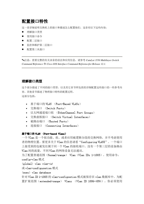
配置接口特性这一章详细说明交换机上的接口和描述怎么配置他们。
这章有以下这些内容:●理解接口类型●使用接口命令●配置二层接口●监控和维护第二层接口●配置第三从接口注意:需要完整的有关该章的语法和应用信息,请参考Catalyst 3550 Multilayer Switch Command Reference和Cisco IOS Interface Command Referencefor Release 12.1.理解接口类型这个部分描述了不同的接口类型,以及其它章节所包括的详细配置这些接口的一些参考内容。
其他章节描述了物理接口特性的配置过程。
这部分包括:•基于端口的VLAN (Port-Based VLANs)•交换端口(Switch Ports)•以太网通道端口组(EtherChannel Port Groups)•交换虚拟接口(Switch Virtual Interfaces)•被路由端口(Routed Ports)•连接接口(Connecting Interfaces)基于端口的VLAN (Port-based Vlans)一个Vlan是一个按功能、组、或者应用被逻辑分段的交换网络,并不考虑使用者的物理位置。
要更多关于Vlan的信息请看“Configuring VLANS”。
一个端口上接受到的包被发往属于同一个Vlan的接收端口。
没有一个第三层的设备路由Vlan间的流量,不同Vlan的网络设备无法通讯。
为了配置普通范围(Normal-range) Vlan(Vlan IDs 1-1005),使用命令:config-vlan模式(global) vlan vlan-id或vlan-configuration模式(exec) vlan database针对Vlan ID 1-1005的vlan-configration模式被保存在vlan数据库中。
为配置扩展范围(extended-range) Vlans (Vlan ID 1006-4094),你必须使用config-vlan模式,并把VTP的模式设为transparent透明模式。
Cisco Catalyst 6500系列交换机 说明书
!"
Cisco Catalyst 6500 系列不但能为企业和电信运营商提供市场领先的服务、性能、端口密度和可 用性,还能提供无与伦比的投资保护能力,包括: ● 最长的网络正常运行时间——利用 Cisco IOS 软件模块化、平台、电源、交换管理引擎、交换 矩阵和集成网络服务冗余性, 提供 1~3 秒的状态化故障切换, 提供应用和服务连续性统一在一 起的融合网络环境,减少关键业务数据和服务的中断。 ● 全面的网络安全性——将切实可行的数千兆位级思科安全解决方案集成到现有网络中, 包括入 侵检测、防火墙、VPN 和 SSL。 ● 可扩展性能——利用分布式转发架构提供高达 400mpps 的转发性能。 ● 能够适应未来发展并保护投资的架构——在同一种机箱中支持三代可互换、可热插拔的模块, 以提高 IT 基础设施利用率,增大投资回报,并降低总拥有成本。 ● 操作一致性—— 3 插槽、6 插槽、9 插槽和 13 插槽机箱配置使用相同的模块、Cisco IOS 软件、 Cisco Catalyst 操作系统软件以及可以部署在网络任意地方的网络管理工具。 ● 卓越的服务集成和灵活性——将安全、 无线局域网服务和内容等高级服务与融合网络集成在一 起,提供从 10/100 和 10/100/1000 以太网到万兆以太网,从 DS0 到 OC-48 的各种接口和密度, 并能够在任何部署项目中端到端地执行。
●
!"#
● ● ● ●
!"#$
在所有 Cisco Catalyst 6500 系列平台上提供集成式 IP 通信 提供 10/100 和 10/100/1000 线卡,可借助子卡进行现场升级以支持以太网供电 支持预标准思科馈线电源和基于标准的 IEEE 802.3af 以太网供电(PoE) 可为公共电话网(PSTN)接入、传统电话、传真和 PBX 连接提供高密度的 T1/E1 和 FXS 的 VoIP 语音网关接口
6500交换机配置维护手册

6500交换机配置维护手册(Native IOS)目录1. 设备硬件和连接设备 (3)1.1.机箱组件和进风试图 (3)1.2.3000 W电源规格 (6)1.3.WS-SUP270-3B (8)1.4.WS-X6408-GBIC (9)1.5.从CONSOLE连接 (9)1.6.远程TELNET连接 (12)2. 基本信息配置 (13)2.1.配置机器名、TELNET、密码 (13)2.2.配置SNMP网管串 (13)3. 冗余及系统高可用性配置 (14)3.1.同步S UPERVISOR E NGINE配置 (14)3.2.查看S UPERVISOR E NGINE冗余 (15)3.3.向冗余S UPERVISOR E NGINE拷贝IOS文件 (16)4. 端口设置 (18)4.1.基本设置 (18)4.2.配置三层端口 (19)5. 配置二层端口 (20)5.1.配置T RUNK: (20)6. 配置HSRP (22)6.1.配置二层普通交换接口 (22)6.2.清除二层接口配置 (22)7. 配置VLAN (24)8. 动态路由协议--OSPF配置 (26)Cisco Systems Inc8.1.启用OSPF动态路由协议 (26)8.2.定义参与OSPF的子网 (26)8.3.OSPF区域间的路由信息汇总 (26)8.4.配置密码验证 (27)8.5.设置产生缺省路由 (27)9. 交换机维护 (29)9.1.交换机IOS保存和升级 (29)9.2.交换机密码恢复 (29)9.3.设备IOS版本检查 (31)9.4.设备CPU利用状况检查 (32)9.5.设备MEMORY利用状况检查 (32)9.6.设备模块运行状况检查 (33)9.7.设备系统电源及风扇检查 (33)9.8.设备运行温度检查 (34)9.9.设备系统L OG检查 (34)Cisco Systems Inc1. 设备硬件和连接设备1.1. 机箱组件和进风试图机箱组件进风试图1.2. 3000 W 电源规格列出了电源供应器LED及其含义。
(完整版)思科交换机配置维护手册

思科交换机配置维护手册目录一、端口配置1.1 配置一组端口当使用interface range命令时有如下的规则:•有效的组范围:o vlan从1 到4094o fastethernet槽位/{first port} - {last port}, 槽位为0o gigabitethernet槽位/{first port} - {last port},槽位为0o port-channel port-channel-number - port-channel-number, port-channel号从1到64•端口号之间需要加入空格,如:interface range fastethernet 0/1 – 5是有效的,而interface range fastethernet 0/1-5是无效的.•interface range命令只能配置已经存在的interface vlan•所有在同一组的端口必须是相同类别的。
见以下例子:Switch# configure terminalSwitch(config)# interface range fastethernet0/1 - 5Switch(config-if-range)# no shutdown以下的例子显示使用句号来配置不同类型端口的组:Switch# configure terminalSwitch(config)# interface range fastethernet0/1 - 3, gigabitethernet0/1 - 2 Switch(config-if-range)# no shutdown1.2 配置二层端口1.2.1 配置端口速率及双工模式Switch# configure terminalSwitch(config)# interface fastethernet0/3 Switch(config-if)# speed 10Switch(config-if)# duplex half1.2.2 端口描述1.2.3 配置三层口Catalyst 3750支持三种类型的三层端口: •SVIs: 即interface vlan•三层以太网通道口(EtherChannel)•.路由口:路由口是指某一物理端口在端口配置状态下用no switchport命令生成的端口所有的三层都需要IP地址以实现路由交换配置步骤如下:配置举例如下:Switch# configure terminalEnter configuration commands, one per line. End with CNTL/Z.Switch(config)# interface gigabitethernet0/2Switch(config-if)# no switchportSwitch(config-if)# ip address 192.20.135.21 255.255.255.0 Switch(config-if)# no shutdownSwitch(config-if)# endshow ip interface命令:Switch# show ip interface gigabitethernet0/2 GigabitEthernet0/2 is up, line protocol is upInternet address is 192.20.135.21/24Broadcast address is 255.255.255.255Address determined by setup commandMTU is 1500 bytesHelper address is not setDirected broadcast forwarding is disabled<output truncated>1.3 监控及维护端口1.3.1 监控端口和控制器的状态主要命令见下表:举例如下:Switch# show interfaces statusPort Name Status Vlan Duplex Speed TypeGi0/1 connected routed a-full a-100 10/100/1000Base TXGi0/2 wce server 20.20.2 disabled routed auto auto 10/100/1000Base TX Gi0/3 ip wccp web-cache notconnect routed auto auto 10/100/1000Base TX Gi0/4 notconnect routed auto auto 10/100/1000Base TX Gi0/5 notconnect routed auto auto 10/100/1000Base TX Gi0/6 disabled routed auto auto 10/100/1000Base TX Gi0/7 disabled routed auto auto 10/100/1000Base TX Gi0/8 disabled routed auto 100 10/100/1000Base TX Gi0/9 notconnect routed auto auto 10/100/1000Base TX Gi0/10 notconnect routed auto auto 10/100/1000Base TX Gi0/11 disabled routed auto auto unknownGi0/12 notconnect routed auto auto unknownSwitch# show interfaces fastethernet 0/1 switchportName: Fa0/1Switchport: EnabledAdministrative Mode: static accessOperational Mode: downAdministrative Trunking Encapsulation: dot1qNegotiation of Trunking: OffAccess Mode VLAN: 1 (default)Trunking Native Mode VLAN: 1 (default)Trunking VLANs Enabled: ALLPruning VLANs Enabled: 2-1001Protected: falseUnknown unicast blocked: disabledUnknown multicast blocked: disabledVoice VLAN: dot1p (Inactive)Appliance trust: 5Switch# show running-config interface fastethernet0/2Building configuration...Current configuration : 131 bytes!interface FastEthernet0/2switchport mode accessswitchport protectedno ip addressmls qos cos 7mls qos cos overrideend1.3.2 刷新、重置端口及计数器Clear命令目的clear counters [interface-id] 清除端口计数器.clear interface interface-id重置某一端口的硬件逻辑clear line [number | console 0 | vty number] 重置异步串口的硬件逻辑Note clear counters 命令只清除用show interface所显示的计数,不影响用snmp得到的计数举例如下:Switch# clear counters fastethernet0/5Clear "show interface" counters on this interface [confirm] ySwitch#*Sep 30 08:42:55: %CLEAR-5-COUNTERS: Clear counter on interface FastEthernet0/5by vty1 (171.69.115.10)可使用clear interface或clear line命令来清除或重置某一端口或串口,在大部分情况下并不需要这样做:Switch# clear interface fastethernet0/51.3.3 关闭和打开端口使用no shutdown命令重新打开端口.举例如下:Switch# configure terminalSwitch(config)# interface fastethernet0/5Switch(config-if)# shutdownSwitch(config-if)#*Sep 30 08:33:47: %LINK-5-CHANGED: Interface FastEthernet0/5, changed state to a administratively downSwitch# configure terminalSwitch(config)# interface fastethernet0/5Switch(config-if)# no shutdownSwitch(config-if)#*Sep 30 08:36:00: %LINK-3-UPDOWN: Interface FastEthernet0/5, changed state to up二、配置VLAN2.1 VLAN论述一个VLAN就是一个交换网,其逻辑上按功能、项目、应用来分而不必考虑用户的物理位置。
- 1、下载文档前请自行甄别文档内容的完整性,平台不提供额外的编辑、内容补充、找答案等附加服务。
- 2、"仅部分预览"的文档,不可在线预览部分如存在完整性等问题,可反馈申请退款(可完整预览的文档不适用该条件!)。
- 3、如文档侵犯您的权益,请联系客服反馈,我们会尽快为您处理(人工客服工作时间:9:00-18:30)。
6500交换机配置维护手册(Native IOS)目录1. 连接设备 (3)1.1.从CONSOLE连接 (3)1.2.远程TELNET连接 (5)2. 基本信息配置 (5)2.1.配置机器名、TELNET、密码 (5)2.2.配置SNMP网管串 (5)3. 冗余及系统高可用性配置 (6)3.1.同步S UPERVISOR E NGINE配置 (6)3.2.查看S UPERVISOR E NGINE冗余 (7)3.3.向冗余S UPERVISOR E NGINE拷贝IOS文件 (8)4. 端口设置 (9)4.1.基本设置 (9)4.2.配置三层端口 (10)5. 配置二层端口 (10)5.1.配置T RUNK: (10)6. 配置HSRP (11)6.1.配置二层普通交换接口 (12)6.2.清除二层接口配置 (12)7. 配置VLAN (12)8. 动态路由协议--OSPF配置 (13)8.1.启用OSPF动态路由协议 (14)8.2.定义参与OSPF的子网 (14)8.3.OSPF区域间的路由信息汇总 (14)8.4.配置密码验证 (15)8.5.设置产生缺省路由 (15)9. 交换机维护 (16)9.1.交换机IOS保存和升级 (16)9.2.交换机密码恢复 (16)1. 连接设备1.1. 从console连接第一次对6000交换机进行配置,必须从console进入。
首先先将机器上架,按要求接好电源,然后用随机附带的Console线和转接头将交换机的console口与PC的串口相联,如下:Com口设置如下:∙9600 baud∙8 data bits∙No parity∙ 2 stop bits检查电源无误后,开电,可能会出现类似下面的显示,按黑粗体字回答:System Bootstrap, Version 6.1(2)Copyright (c) 1994-2000 by cisco Systems, Inc.c6k_sup2 processor with 131072 Kbytes of main memoryrommon 1 > boot slot0:c6sup22-jsv-mz.121-5c.EX.binSelf decompressing the image : ################################################################################################################################ ############################################################################### ############################################################################### ############################################################################### [OK]Restricted Rights LegendUse, duplication, or disclosure by the Government issubject to restrictions as set forth in subparagraph(c) of the Commercial Computer Software - RestrictedRights clause at FAR sec. 52.227-19 and subparagraph(c) (1) (ii) of the Rights in Technical Data and ComputerSoftware clause at DFARS sec. 252.227-7013.cisco Systems, Inc.170 West Tasman DriveSan Jose, California 95134-1706Cisco Internetwork Operating System SoftwareIOS (tm) MSFC2 Software (C6MSFC2-BOOT-M), Version 12.1(3a)E4, EARLY DEPLOYMENT R ELEASE SOFTWARE (fc1)Copyright (c) 1986-2000 by cisco Systems, Inc.Compiled Sat 14-Oct-00 05:33 by eaarmasImage text-base: 0x30008980, data-base: 0x303B6000cisco Cat6k-MSFC2 (R7000) processor with 114688K/16384K bytes of memory.Processor board ID SAD04430J9KR7000 CPU at 300Mhz, Implementation 39, Rev 2.1, 256KB L2, 1024KB L3 CacheLast reset from power-onX.25 software, Version 3.0.0.509K bytes of non-volatile configuration memory.16384K bytes of Flash internal SIMM (Sector size 512K).Press RETURN to get started!--- System Configuration Dialog ---Would you like to enter the initial dialog? [yes]: no回答:NO,进入手工配置,在router>下,输入enable回车,进入全局模式1.2. 远程telnet连接当完成交换机配置,并起给交换机配置了管理地址,就可以直接采用远程telnet 登陆进入交换机了,但是必须先配置line vty的密码和enable密码才能允许远程登陆。
2. 基本信息配置2.1. 配置机器名、telnet、密码1.在全局模式下,用conf t,进入配置模式,进行以下的配置:管理方面的配置:service timestamps debug datetime localtimeservice timestamps log datetime localtimeservice password-encryptionhostname xxxxenable secret 0 xxxxxline vty 0 4exec-timeout 30 0password 0 xxxxlogin2.2. 配置snmp网管串conf tsnmp-server community xxxxxx ro(只读)或snmp-server community xxxxxx rw(读写)3. 冗余及系统高可用性配置6000系列支持双supervisor engines或加强的高可用系统(EHSA),允许第二块supervisor engines处于standby模式或EHSA状态,在主用supervisor engines 有问题时进行切换(切换过程中会照成网络的暂时中断),当交换机加电后,EHSA会缺省地在二supervisor engine上运行(slot 1 or 2), 其中之一会成为活动的。
注意:二块supervisor engine必须有一致的IOS,内存等。
3.1. 同步Supervisor Engine配置在正常的操作过程中,初始配置(startup-config)及config-registers配置缺省会在二supervisor engines之间同步. 发生切换后,新的活动supervisor engine会运行当前的配置。
可按以下的步骤手工同步二块supervisor engines:注意 auto-sync standard命令不同步bootvariables.配置如下:Router(config)# redundancyRouter(config-r)# main-cpuRouter(config-r-mc)# auto-sync standardRouter(config-r-mc)# auto-sync bootvarRouter(config-r-mc)# endRouter# copy running-config startup-config注意手工同步某参数后,会使原缺省的同步特征3.2. 查看Supervisor Engine冗余如下Router# show module allMod Ports Card Type Model Serial No.--- ----- -------------------------------------- ------------------ -----------1 2 Catalyst 6000 supervisor 2 (Standby) WS-X6K-SUP2-2GE SAD04450LEU2 2 Catalyst 6000 supervisor 2 (Active) WS-X6K-SUP2-2GE SAD04160FSR3 48 SFM-capable 48-port 10/100 Mbps RJ45 WS-X6548-RJ-45 SAD050105Y04 48 SFM-capable 48-port 10/100 Mbps RJ45 WS-X6548-RJ-45 SAD0440799G5 16 SFM-capable 16 port 10/100/1000mb RJ45 WS-X6516-GE-TX SAD05030P0W7 0 Switching Fabric Module-136 (Active) WS-X6500-SFM2 SAD044406638 0 Switching Fabric Module-136 (Standby) WS-X6500-SFM2 SAD04510at49 16 Pure SFM-mode 16 port 1000mb GBIC WS-X6816-GBIC SAD044904N711 16 Pure SFM-mode 16 port 1000mb GBIC WS-X6816-GBIC SAD04390CCJ12 16 Pure SFM-mode 16 port 1000mb GBIC WS-X6816-GBIC SAD04260E2413 16 Pure SFM-mode 16 port 1000mb GBIC WS-X6816-GBIC SAD04260E1JMod MAC addresses Hw Fw Sw Status--- ---------------------------------- ------ ------------ ------------ -------1 0001.6461.38a8 to 0001.6461.38a9 1.1 Unknown 6.2(0.106) Ok2 0040.0b14.03e2 to 0040.0b14.03e3 0.220 6.1(2) 6.2(0.106) Ok3 0001.6441.47f0 to 0001.6441.481f 0.303 6.1(3) 6.2(0.106) Ok4 0002.b9ff.e8d0 to 0002.b9ff.e8ff 0.204 6.1(3) 6.2(0.106) Ok5 0001.64f8.3330 to 0001.64f8.333f 0.201 6.1(2) 6.2(0.106) Ok7 0040.0bff.0000 to 0040.0bff.0000 0.107 6.1(3) 6.2(0.106) Ok8 0040.0bff.0000 to 0040.0bff.0000 0.203 6.1(3) 6.2(0.106) Ok9 0002.fc90.0888 to 0002.fc90.0897 0.302 12.1(4r) 12.1(nightly Ok11 0001.64f8.37f0 to 0001.64f8.37ff 0.204 12.1(5r) 12.1(nightly Ok12 0001.64f8.3180 to 0001.64f8.318f 0.105 12.1(5r) 12.1(nightly Ok13 0001.64f8.3190 to 0001.64f8.319f 0.105 12.1(5r) 12.1(nightly OkMod Sub-Module Model Serial Hw Status--- --------------------------- --------------- --------------- ------- -------1 Cat6k MSFC2 daughterboard WS-F6K-MSFC2 SAD044509Y3 1.1 Ok2 Policy Feature Card 2 WS-F6K-PFC2 SAD04130A17 0.305 Ok2 Cat6k MSFC 2 daughterboard WS-F6K-MSFC2 SAD04160DBN 0.306 Ok4 Distributed Forwarding Card WS-F6K-DFC SAD04460KEJ 0.205 Ok5 Distributed Forwarding Card WS-F6K-DFC SAD04460KEL 0.205 Ok9 Distributed Forwarding Card WS-F6K-DFC SAD04440952 0.215 Ok11 Distributed Forwarding Card WS-F6K-DFC SAD04390CCJ 0.215 Ok12 Distributed Forwarding Card WS-F6K-DFC SAD04340BK2 0.118 Ok13 Distributed Forwarding Card WS-F6K-DFC SAD04340BK0 0.118 OkRouter#3.3. 向冗余Supervisor Engine拷贝IOS文件如果二块supervisor Engine与第一块的IOS相同,就不需要做此步使用以下命令将文件拷贝到冗余supervisor engine的slot0:Router# copy source_device:source_filename slaveslot0:target_filename使用以下命令将文件拷贝到冗余supervisor engine的bootflash:Router# copy source_device:source_filenameslavesup-bootflash:target_filename使用以下命令将文件拷贝到冗余MSFC的bootflash:Router# copy source_device:source_filename slavebootflash:target_filename4. 端口设置4.1. 基本设置进入端口配置模式:对于单一端口,在配置模式下输入:interface Ethernet,Fast Ethernet,Gigabit Ethernet x/y, x为槽位号,y为端口号。