高性能电流模式PWM控制器MXT7111
TC2263(电流模式PWM控制IC)
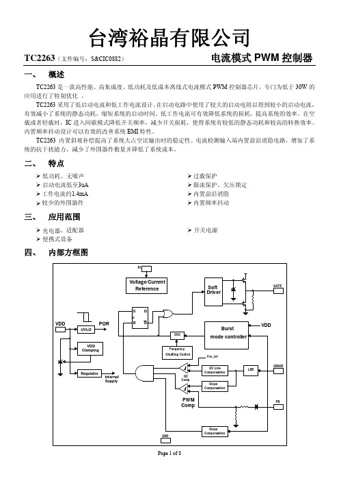
TC2263(文件编号:S&CIC0882) 电流模式PWM 控制器一、 概述TC2263是一款高性能、高集成度、低功耗及低成本离线式电流模式PWM 控制器芯片,专门为低于30W 的应用进行了特别优化 。
TC2263采用了低启动电流和低工作电流设计。
在启动电路中使用了较大的启动电阻以得到较小的启动电流,有效减小了系统的静态功耗,缩短系统的启动时间。
低工作电流可有效降低系统的损耗,提高系统的效率。
在空载或者轻载时,IC 进入间歇模式降低开关频率,减少开关损耗,使得系统有较低的静态功耗和较高的转换效率。
内置频率抖动设计可以有效的改善系统EMI 特性。
TC2263 内置斜坡补偿提高了系统大占空比输出时的稳定性。
电流检测输入端内置前沿消隐电路,增加了系统的抗干扰能力,减少了外围器件数量并降低了系统成本。
二、 特点低功耗、无噪声 启动电流低至3uA 工作电流约1.4mA 较少的外围器件过载保护限流保护、欠压锁定 内置前沿消隐 内置频率抖动三、 应用范围充电器、适配器 开关电源TC2263(文件编号:S&CIC0882)电流模式PWM控制器七、 最大额定值参数额定值VDD DC电源电压30VVDD钳位电压34VVDD DC 钳位电流10mAV FB输入电压-0.3-7VV SENSE输入电压-0.3-7VV RI输入电压-0.3-7V工作结温 -20℃-150℃贮存温度 -55℃-160℃注:最大允许额定值是指超过这些值可能会损坏器件,在这些条件式之下是不利于的器件工作的。
器件连续工作在最大允许额定值下可能影响器件可靠性。
所有的电压均是相对于器件GND的电压差。
八、 电气特性(参数都是在TA= 25℃的工作条件下测得,有另有注明的除外)符号参数测试条件最小值典型值最大值单位电源电压(VDD)I_VDD_Startup VDD启动电流V DD=12.5V,R I=100K 3 20uA I_VDD_Ops 芯片工作电流V DD=16V,R I=100K,V FB=3V 1.4 mA UVLO(ON) 进入欠压保护7.8 8.8 9.8 V UVLO(OFF) 退出欠压保护13 14 15 V VDD_Clamp VDD 钳位电压I VDD=10mA 34 V 反馈输入 (FB Pin)A VCS PWM 输入增益△V FB/△V CS 2.0 V/V V FB_Open FB开路电压 4.8 V I FB_Short FB pin短路电流 0.8 mAV TH_0D PWM 0占空比时FB门限电压VDD=16V, RI=100Kohm0.75VV TH_PL 过载保护FB 门限电压3.7 V T D_PL 过载保护延时 35 mSecZ FB_IN FB输入阻抗 6KohmDC_MAX 最大占空比V DD=18V, R I=100Kohm,F B=3V, CS=075 % 电流检测输入 (Sense Pin)T_blanking 前沿消隐时间RI=100Kohm 300 ns Z SENSE_IN CS输入阻抗 40KohmT D_OC 过流检测延时VDD=16V, CS>VTH_OC,FB=3.3V75 nSecVTH_OC PWM零占空比时过流门限电压FB=3.3V, RI=100Kohm0.70 0.75 0.80 V振荡频率Fosc 正常振荡频率RI=100Kohm 60 65 70 KHz△f_Temp 频率温度稳定度VDD = 16V, RI=100Kohm,T A -20℃ to 100℃ 5 % Δf_VDD频率电压稳定VDD = 12-25V, RI=100Kohm 5 %TC2263(文件编号:S&CIC0882)电流模式PWM控制器RI_range RI电阻设置范围50 100 150KohmV_RI_open RI 开路电压 2 V F osc_BM 间歇模式频率VDD = 16V, RI = 100Kohm 22 KHz驱动开关管输出VOL GATE输出低电平VDD = 16V, Io = -20 mA0.8V VOH GATE输出高电平VDD = 16V, Io = 20 mA10 V V_Clamp GATE输出钳位电压18 VT_r GATE输出上升沿时间VDD = 16V, CL = 1nf220 nSecT_f GATE输出下降沿时间VDD = 16V, CL = 1nf70 nSec频率抖动Δf_OSC 频率调制范围/基频RI=100K-3 3 % f_shuffling 抖动频率RI=100K 64 Hz九、 特性(典型参数)(VDD = 16V, RI = 100 Kohm, T A = 25o C 除非另有注明。
LN9T11 LN9T39 LN9T36 LN9T33力生美电源管理芯片
LN9T11/LN9T39/LN9T36/LN9T33描述:LN9T11 是高性能、高集成度电流模式PWM 控制器,可以方便地在应用中构建满足CoC V5 及Do2016 等6 级能效的低待机功耗、低成本、高性能的解决方案。
PWM开关频率由芯片内部设定并具有全温度补偿,其最大值被设定在65kHz. 在空载或轻载条件下,IC可工作在智能断续模式以减少开关损失,因此可以达到很好的转换效率同时又具有较小的待机功耗。
很低的VDD 启动电流与工作电流可以使LN9T11拥有非常高的可靠性和使用寿命,一个较大阻值的电阻即可用来完成电路的启动工作,这也减少了启动电阻的损失,进一步降低了系统待机功耗。
内置的电流斜坡补偿功能则极大地优化了电路在较大的PWM 占空比时的可靠性LN9T33 是一款高性能、高集成度电流模式PWM控制器功率开关,可以方便地在应用中构建满足CoC V5 及DoE 6 级能效的低待机功耗、低成本、高性能的解决方案。
PWM开关频率由芯片内部设定并具有全温度补偿,其最大值被设定在65kHz. 在空载或轻载条件下,IC 可工作在智能断续模式以减少开关损失,因此可以达到很好的转换效率同时又具有较小的待机功耗。
很低的VDD 启动电流与工作电流可以使LN9T33 拥有非常高的可靠性和使用寿命,一个较大阻值的电阻即可用来完成电路的启动工作,这也减少了启动电阻的损失,进一步降低了系统待机功耗。
内置的电流斜坡补偿功能则极大地优化了电路在较大的PWM占空比时的可靠性,避免了可能出现的次谐波振荡现象。
内置的前沿消隐电路避免了电感开启电流尖峰对电流采样的干扰以及缓冲二极管反向恢复电流的影响LN9T39 是一款高性能、高集成度电流模式PWM控制器功率开关,可以方便地在应用中构建满足CoC V5 及DoE 6 级能效的低待机功耗、低成本、高性能的解决方案。
PWM开关频率由芯片内部设定并具有全温度补偿,其最大值被设定在65kHz. 在空载或轻载条件下,IC 可工作在智能断续模式以减少开关损失,因此可以达到很好的转换效率同时又具有较小的待机功耗。
电源控制器XY6112

一、 概述XY6112为高性能,电流模式PWM 控制器。
内置高压功率管,在AC85-350V的宽电压范围内提供高达12W 的连续输出功率。
高性价比的双极型制作工艺生产的控制芯片,结合高压功率管的一体化封装最大程度上节约了产品的整体成本。
该电源控制器可工作于典型的反激电路拓扑中,构成简洁的AC/DC转换器。
IC内部的启动电路可利用功率开关管本身的放大作用完成启动,很大程度地降低了启动电阻的功率消耗;而在输出功率较小时IC将自动降低工作频率,从而实现了很低的待机功耗;专利的驱动电路使开关管工作于临界饱和状态,提高了系统的工作效率,使系统可以轻松满足“能源之星”关于待机功耗和效率的认证要求。
在实现待机降频的同时限制工作频率进入音频范围,防止音频噪音的产生。
4-12V的工作电压范围提供了轻松的VCC电压设计空间,同时VCC达到12V时芯片内部保护,限制输出功能可防止光耦或反馈电路损坏引起的输出电压过高,IC内部还提供了完善的防过载与防饱和功能,可实时防范过载、变压器饱和、输出短路等异常状况,提高了电源的可靠性。
IC内部还集成了温度保护功能,在系统过热的情况下降低输出功率,或关闭输出。
现可提供DIP8的标准封装和满足ROHS标准。
图1:电路框图二、 特点 满足AC85-350V的输入电压范围的设计要求。
具有待机降频功能,无音频噪音问题,待机功耗可做到0.25W以下 高效的驱动电路,比同类产品效率高4-5%。
和同类产品比芯片发热减小40% 能满足能源之星2.0关于效率和待机功耗的最新要求。
具有温度补偿功能,精确电流控制 低启动电流和低工作电流,4-12V的宽工作压范围。
宽电压连续输出功率可达12W, 峰值输出功率可达15W 过温保护功能(OTP) 过压保护功能(OVP) 可靠性高 可实现无Y电容系统设计极少的外围元器件,整体方案成本低三、 应用范围9小家电(如:电磁炉)9充电器9电源适配器(如通信终端产品) 9DVD/DVB电源电脑,LCD TV待机电源四、 引脚功能描述管脚 符号 管脚定义描述1 OB 功率管基极,启动电流输入,外接启动电阻2 VCC 供电脚3 GND 接地脚4 CT 开关频率设定脚,外接定频电容5 FB 反馈脚6 IS 开关电流取样与限制设定脚,外接电流取样电阻7,8 OC 输出脚,接开关变压器备注:PCB Layout时应将Pin6与Pin7之间保留1mm以上的安全距离,避免产生放电现象。
士兰微电子SD7530 LED照明高功率因数反激式PWM控制器说明书

高功率因数反激式PWM控制器
日光灯
产品规格分类
产品名称 封装形式 打印名称 材料 包装
无铅料管SD7530 DIP-8-300-2.54
SD7530
无铅料管
SD7530S
SD7530S SOP-8-225-1.27
无铅编带SD7530STR SOP-8-225-1.27
SD7530S
内部框图
40
OL -600/800
误差
放大器
比较器
SD7530说明书
电气参数 (除非特别指定,V
CC
=22V;C O=1nF;-25°C<T amb<125°C)
TEL 158********
SD7530说明书
TEL 158********
管脚描述
封装外形图
SD7530说明书
MOS电路操作注意事项:
静电在很多地方都会产生,采取下面的预防措施,可以有效防止MOS电路由于受静电放电影响而引起的损坏:
• 操作人员要通过防静电腕带接地。
• 设备外壳必须接地。
• 装配过程中使用的工具必须接地。
• 必须采用导体包装或抗静电材料包装或运输。
声明:
•士兰保留说明书的更改权,恕不另行通知!客户在下单前应获取最新版本资料,并验证相关信息是否完整和最新。
•任何半导体产品特定条件下都有一定的失效或发生故障的可能,买方有责任在使用Silan产品进行系统设计和整机制造时遵守安全标准并采取安全措施,以避免潜在失败风险可能造成人身伤害或财产损
失情况的发生!
•产品提升永无止境,我公司将竭诚为客户提供更优秀的产品!
TEL 158********。
R7731A PWM 控制器商品说明书

R7731A-10 August 2011General DescriptionThe R7731A is a high-performance, low cost, low start-up current and current mode PWM controller with burst triple mode to support green mode power saving operation. The R7731A integrates functions of soft start, Under Voltage LockOut (UVLO), Leading Edge Blanking (LEB), Over Temperature Protection (OTP) and internal slope compensation. It provides the users a superior AC/DC power application of higher efficiency, low external component counts and lower cost solution.To protect the external power MOSFET from being damaged by supply over voltage, the R7731A output driver is clamped at 12V. Furthermore, R7731A features fruitful protections like Over Load Protection (OLP) and Over Voltage Protection (OVP) to eliminate the external protection circuits and provide reliable operation. R7731A is available in SOT-23-6 and DIP-8 packages.Burst Triple Mode PWM Flyback ControllerFeaturesz Very Low Start-up Current (<30μA)z 10/14V UVLOz Soft Start Function z Current Mode Controlz Jittering Switching Frequency z Internal Leading Edge Blanking z Built-in Slope Compensationz Burst Triple Mode PWM for Green-Mode z Cycle-by-Cycle Current Limit z Feedback Open Protection z Over Voltage Protectionz Over Temperature Protection z Over Load Protectionz Soft Driving for Reducing EMI z Driver Capability ±200mA z High Noise ImmunityzOpto-Coupler Short ProtectionzRoHS Compliant and Halogen FreeApplicationsz Adaptor and Battery Charger z ATX Standby Power z Set-Top Box (STB)z DVD and CD(R)z TV/Monitor Standby Power zPC PeripheralsOrdering InformationR7731AG : Green (Halogen Free and Pb Free)Note :Richtek products are :` RoHS compliant and compatible with the current require-ments of IPC/JEDEC J-STD-020.` Suitable for use in SnPb or Pb-free soldering processes.Marking InformationIDP= : Product Code W : Date CodeR7731AGN : Product Number YMDNN : Date CodeR7731AGERichTek R7731A GNYMDNNPin Configurations(TOP VIEW)SOT-23-6DIP-8GATE VDD NC CSRTNCCOMP GND VO+VO-* : See Application InformationR7731A-10 August 2011Function Block DiagramVDDRTGATEGNDAbsolute Maximum Ratings(Note 1)z Supply Input Voltage, V DD-------------------------------------------------------------------------------------------------−0.3V to 30V z GATE Pin----------------------------------------------------------------------------------------------------------------------−0.3V to 20V z RT, COMP, CS Pin----------------------------------------------------------------------------------------------------------−0.3V to 6.5V z I DD-------------------------------------------------------------------------------------------------------------------------------10mAz Power Dissipation, P D @ T A = 25°CSOT-23-6----------------------------------------------------------------------------------------------------------------------0.4WDIP-8---------------------------------------------------------------------------------------------------------------------------0.714Wz Package Thermal Resistance (Note 2)SOT-23-6, θJA-----------------------------------------------------------------------------------------------------------------250°C/WDIP-8, θJA----------------------------------------------------------------------------------------------------------------------140°C/Wz Junction T emperature-------------------------------------------------------------------------------------------------------150°Cz Lead Temperature (Soldering, 10 sec.)---------------------------------------------------------------------------------260°Cz Storage T emperature Range----------------------------------------------------------------------------------------------−65°C to 150°C z ESD Susceptibility (Note 3)HBM (Human Body Mode)------------------------------------------------------------------------------------------------4kVMM (Machine Mode)--------------------------------------------------------------------------------------------------------250V Recommended Operating Conditions (Note 4)z Supply Input Voltage, V DD-------------------------------------------------------------------------------------------------12V to 25Vz Operating Frequency-------------------------------------------------------------------------------------------------------50k to 130kHz z Junction T emperature Range----------------------------------------------------------------------------------------------−40°C to 125°C z Ambient T emperature Range----------------------------------------------------------------------------------------------−40°C to 85°CElectrical CharacteristicsTo be continuedNote 1. Stresses listed as the above "Absolute Maximum Ratings" may cause permanent damage to the device. These are for stress ratings. Functional operation of the device at these or any other conditions beyond those indicated in the operational sections of the specifications is not implied. Exposure to absolute maximum rating conditions for extended periods may remain possibility to affect device reliability.Note 2. θJA is measured in the natural convection at T A = 25°C on a low effective single layer thermal conductivity test board of JEDEC 51-3 thermal measurement standard.Note 3. Devices are ESD sensitive. Handling precaution is recommended.Note 4. The device is not guaranteed to function outside its operating conditions.Note 5. Guaranteed by design.R7731A-10 August D MAX vs. Temperature7071727374757677787980-40-2020406080100120Temperature (°C)D M A X (%)Typical Operating CharacteristicsV TH vs. Temperature9101112131415-40-25-105203550658095110125Temperature (°C)V D D (V )I DD_ST vs. Temperature10121416182022242628-40-1510356085110135Temperature (°C)I D D _S T (µA)I DD_OP vs. Temperature1.251.301.351.401.451.501.55-40-1510356085110135Temperature (°C)I D D _O P (m A )f OSC vs. Temperature57585960616263-40-1510356085110135Temperature (°C)f O S C (k H z )V COMP vs. Temperature5.405.445.485.525.565.60-40-2020406080100120Temperature (°C)V C O M PR7731A-10 August 2011V CLAMP vs. V DD78910111213111213141516171819202122V DD (V)V C L A M P (V)V GATE_OFF vs. V DD400425450475500525550575600111213141516171819202122V DD (V)V G A T E _O F F (m V)I SUPPLY vs. Temperature0.300.350.400.450.50-40-2020406080100120Temperature (°C)I S U P P L Y (m A)I SUPPLY vs. V DD0.4080.4100.4120.4140.4160.4180.4200.4220.4240.426111213141516171819202122V DD (V)I S U P P L Y (m A)V CLAMP vs. Temperature10.010.511.011.512.012.513.0-40-1510356085110135Temperature (°C)V C L A M P (V)GATE vs. Temperature50100150200250300350-40-25-105203550658095110125Temperature (°C)G A T E (n s )V CSTH vs. Temperature0.8000.8150.8300.8450.8600.8750.890-40-25-105203550658095110125Temperature (°C)V C S T H (V )R7731A-10 August 2011Application InformationUVLOUnder Voltage LockOut (UVLO) block is to ensure V DD has reached proper operation voltage before we enable the whole IC blocks. To provide better temperature coefficient and precise UVLO threshold voltage, the reference voltage of hysteresis voltage (10V / 14V) is from band-gap block directly. By this way, R7731A can operate more reliable in different environments.The maximum start-up current (30μA) is only for leakage current of IC at UVLO(on)-0.1V. The external al-capacitor on VDD may have 5 to 6μA extra leakage current. So designed start-up current of the system should exceed 36μA or more and IC can start up normally. In addition,designed start-up current of system should be less than 380μA, and IC can work normally at hiccup mode.Jittering OscillatorFor better EMI performance, R7731A will operate the system with ±6% frequency deviation around setting frequency.To guarantee precise frequency, it is trimmed to 5%tolerance. It also generates slope compensation saw-tooth,75% maximum duty cycle pulse and overload protection slope. By adjusting resistor of RT pin according to the following formula :Figure 1. CompetitorV CSV OUTV CS(500mV/Div)V OUT (2V/Div))(k R 6500(kHz)f T OSCΩ=It can typically operate between 50kHz to 130kHz. Note that RT pin can 't be short or open otherwise oscillator will not operate.Built-in Slope CompensationTo reduce component counts, slope compensation is implemented by internal built-in saw-tooth. Since it 's built-in, it 's compromised between loop gain and sub-harmonic reduction. In general design, it can cancel sub-harmonic to 90Vac.Leading Edge Blanking (LEB)MOSFET C OSS , secondary rectifier reverse recovery current and gate driver sourcing current comprise initial current spike. The spike will seriously disturb current mode operation especially at light load and high line. R7731A provides built-in 420ns LEB to guarantee proper operation in diverse design.Noise ImmunityCurrent mode controller is very sensitive to noise. R7731A takes the advantages of Richtek long term experience in designing high noise immunity current mode circuit and layout. Also, we amplify current sense signal to compare with feedback signal instead of dividing feedback signal.All the effort is to provide clean and reliable current mode operation.Soft-StartDuring initial power on, especially at high line, current spike is kind of unlimited by current limit. Therefore,besides cycle-by-cycle current limiting, R7731A still provides soft-start function. It effectively suppresses the start-up current spike. As shown in the Figure 1 and Figure 2, the start-up V CS is about 0.3V lower than competitor. The typical soft-start duration is 4ms (R T =100k Ω). Again, this will provide more reliable operation and possibility to use smaller current rating power MOSFET .Gate DriverA totem pole gate driver is fine tuned to meet both EMI and efficiency requirement in low power application. An internal pull low circuit is activated after pretty low V DD to prevent external MOSFET from accidentally turning on during UVLO.Burst Triple ModeTo fulfill green mode requirement, there are 3 operation modes in R7731A. Please also refer to Figure 3 for details.`PWM ModeFor most of load condition, the circuit will run at traditional PWM current mode.`Burst ModeDuring light load, switching loss will dominate the power efficien cy calculation. This mode is to cut switching loss. As shown in Figure 3, when the output load gets light, feedback signal drops and touches V BURL (Typical value is 1.75V). Clock signal will be blanked and system ceases to switching. After V OUT drops and feedback signal goes back to V BURH (1.8V, typically), switching will be resumed. Burst mode so far is widely used in low power application because it 's simple, reliable and will not have any patent infringement issue.`VDD Holdup ModeWhen the V DD drops down to V DD turn off threshold voltage, the system will be shut down. During shut down period, controller does nothing to any load change and might cause V OUT down. To avoid this, when V DD drops to a setting threshold, 11V, the hysteresis comparator will bypass PWM and burst mode loop and force switching at a very lo w level to supply energy to VDD pin. The designed value is 11.25V with 0.5V hysteresis band.Furthermore, VDD holdup mode is only designed to prevent V DD from touching turn off threshold voltage under light load or load transient moment. Relative to burst mode, switching loss will increase on the system at VDD holdup mode, so it is highly recommended that the system should avoid operating at this mode during light load or no load condition, normally.Figure 3. Burst Triple ModeFigure 2. R7731AV CSV OUTV CS(500mV/Div)V OUT (2V/Div)V V V V V V VR7731A-10 August 2011ProtectionR7731A provides fruitful protection functions that intend to protect system from being damaged. All the protection functions can be listed as below :`Cycle-by-Cycle Current LimitThis is a basic but very useful function and it can be implemented easily in current mode controller.`Over Load ProtectionLong time cycle-by-cycle current limit will lead to system thermal stress. To further protect system, system will be shut down after about 4096 clock cycles. it 's about 60ms delay in 67kHz operation. After shutdown, system will resume and behave as hiccup. By proper start-up resistor design, thermal will be averaged to an acceptable level over the ON/OFF cycle of IC. This will last until fault is removed. #It's highly recommended to add a resistor in parallel with the opto-coupler. T o provide sufficient bias current to make TL-431 regulate properly,1.2k Ω resistor is suggested.`Brownout ProtectionDuring heavy load, this will trigger 60ms protection and shut down the system. If it 's in light load condition,system will be shut down after V DD is running low and triggers UVLO.` OVPOutput voltage can be roughly sensed by VDD pin.If the sensed voltage reaches 27V threshold, system will be shut down after 20μs deglitch delay.`Feedback Open and Opto-Coupler ShortThis will trigger OVP or 60ms delay protection. It depends on which one occurs first.`OTPInternal OTP function will protect the controller itself from suffering thermal stress and permanent damage. It stops the system from switching until the temperature is under threshold level. Meanwhile, if V DD reaches V DD turn off threshold voltage, system will hiccup till over temperature condition is gone.Figure 4. R-C Filter on CS PinNegative Voltage Spike on Each PinNegative voltage (< −0.3V) on each pin will cause substrate injection. It leads to controller damage or circuit false trigger. Generally, it happens at CS pin due to negative spike because of improper layout or inductive current sense resistor. Therefore, it is highly recommended to add a R-C filter to avoid CS pin damage, as shown in Figure 4. Proper layout and careful circuit design should be done to guarantee yield rate in mass production.Auxiliary Ground (c)ICGround (d)MOSFET Ground (b)Figure 5. PCB Layout GuideLayout ConsiderationA proper PCB layout can abate unknown noise interference and EMI issue in the switching power supply. Please refer to the guidelines when you want to design PCB layout for switching power supply:The current path (1) from bulk capacitor, transformer,MOSFET, Rcs return to bulk capacitor is a huge high frequency current loop. It must be as short as possible to decrease noise coupling and kept a space to other low voltage traces, such as IC control circuit paths, especially.Besides, the path (2) from RCD snubber circuit to MOSFET is also a high switching loop, too. So keep it as small as possible.It is good for reducing noise, output ripple and EMI issue to separate ground traces of bulk capacitor (a), MOSFET (b), auxiliary winding (c) and IC control circuit (d). Finally,connect them together on bulk capacitor ground (a). The areas of these ground traces should be kept large.Placing bypass capacitor for abating noise on IC is highly recommended. The bypass capacitor should be placed as close to controller as possible.To minimize reflected trace inductance and EMI minimize the area of the loop connecting the secondary winding,the output diode, and the output filter capacitor. In addition,provide sufficient copper area at the anode and cathode terminal of the diode for heatsinking. Provide a larger area at the quiet cathode terminal. A large anode area can increase high-frequency radiated EMI.R7731A-10 August 2011Outline DimensionA1HSOT-23-6 Surface Mount PackageRichtek Technology CorporationHeadquarter5F, No. 20, Taiyuen Street, Chupei City Hsinchu, Taiwan, R.O.C.Tel: (8863)5526789 Fax: (8863)5526611Information that is provided by Richtek Technology Corporation is believed to be accurate and reliable. Richtek reserves the right to make any change in circuit design,specification or other related things if necessary without notice at any time. No third party intellectual property infringement of the applications should be guaranteed by users when integrating Richtek products into any application. No legal responsibility for any said applications is assumed by Richtek.Richtek Technology CorporationTaipei Office (Marketing)5F, No. 95, Minchiuan Road, Hsintien City Taipei County, Taiwan, R.O.C.Tel: (8862)86672399 Fax: (8862)86672377Email:*********************8-Lead DIP Plastic Package。
OB2273互换的高性能电流模式PWM控制器MXT7110
OB2273互换的高性能电流模式PWM控制器MXT7110
MXT7110是高性能,低待机功耗(小于100mW)和成本效益的离线反激式转换器的应用进行了优化,高度集成的电流模式PWM控制IC。
它提供完整的保护范围,自动恢复,包括逐周期电流限制(OCP),过载保护(OLP),VDD,欠压锁定(UVLO)。
它还提供锁存关闭包括过温保护(OTP),过电压(固定或可调)保护(OVP)的保护。
特点:
◆电源软启动降低MOSFET的VDS应力
◆改善EMI的频率抖动
◆改善效率和待机功率最小化的扩展burst模式设计
◆音频无噪声运行
◆固定的65kHz开关频率
◆全面的保护范围
◇VDD,根据迟滞电压锁定(UVLO)
◇循环周期的恒定输出功率限制的电流阈值设置的通用输入电压范围
◇过载保护(OLP)与自动恢复
◇过温保护(OTP)与锁存关闭
◇VDD过电压保护(OVP)闩锁关闭
◇通过外部稳压可调过压保护
◆SOT23-6封装,符合RoHS
应用范围:
离线AC / DC反激式转换器
◆LED显示器电源供应器
◆上网本/平板电脑适配器
◆电池充电器
◆电源适配器
◆机顶盒电源
◆开放式框架开关电源
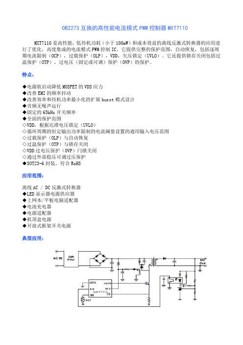
典型应用:。
高性能电流模式PWM控制器MXT7208
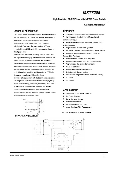
High Precision CC/CV Primary-Side PWM Power SwitchGENERAL DESCRIPTIONis a high performance offline PWM Power switchfor low power AC/DC charger and adapter applications. It operates in primary-side sensing and regulation. Consequently, opto-coupler and TL431 could be eliminated. Proprietary Constant Voltage (CV) and Constant Current (CC) control is integrated as shown in the figure below.In CC control, the current and output power setting can be adjusted externally by the sense resistor Rs at CS pin. In CV control, multi-mode operations are utilized to achieve high performance and high efficiency. In addition, good load regulation is achieved by the built-in cable drop compensation. Device operates in PFM in CC mode as well at large load condition and it operates in PWM with frequency reduction at light/medium load.offers power on soft start control and protectioncoverage with auto-recovery features including Cycle-by-Cycle current limiting, VDD OVP, VDD clamp and UVLO. Excellent EMI performance is achieved with Power-Source proprietary frequency shuffling technique.High precision constant voltage (CV) and constant current (CC) can be achieved by FEATURES⏹±5% Constant Voltage Regulation at Universal AC input ⏹High Precision Constant Current Regulation at Universal AC input⏹Primary-side Sensing and Regulation Without TL431 and Opto-coupler⏹Programmable CV and CC Regulation⏹Adjustable Constant Current and Output Power Setting ⏹Built-in Secondary Constant Current Control with Primary Side Feedback⏹Built-in Adaptive Current Peak Regulation ⏹Built-in Primary winding inductance compensation ⏹Programmable Cable drop Compensation ⏹Power on Soft-start⏹Built-in Leading Edge Blanking (LEB)⏹Cycle-by-Cycle Current Limiting⏹VDD Under Voltage Lockout with Hysteresis (UVLO)⏹VDD OVP ⏹VDD ClampAPPLICATIONS⏹Low Power AC/DC offline SMPS for⏹Cell Phone Charger ⏹Digital Cameras Charger ⏹Small Power Adapter⏹Auxiliary Power for PC, TV etc.⏹Linear Regulator/RCC Replacementis offered in SOT23-6 package.Product SpecificationTYPICAL APPLICATIONMXT7208MXT7208MXT7208MXT7208MXT7208High Precision CC/CV Primary-Side PWM Power SwitchPin ConfigurationThe pin map is shown as below for SOT23-6.Absolute Maximum RatingsProduct SpecificationTERMINAL ASSIGNMENTSGENERAL INFORMATIONPin Num.Pin Name I/O Description 1GND P Ground 2GD O Drive MOSFET 3CS I Current sense input4FB I Feedback5COMP I Loop Compensation for CV Stability6VDD P Power SupplyBLOCK DIAGRAMHigh Precision CC/CV Primary-Side PWM Power SwitchELECTRICAL CHARACTERISTICSProduct Specification(TA = 25C, VDD=VDDG=16V, if not otherwise noted)1. Freq_Max indicates IC internal maximum clock frequency. In system application, the maximum operation frequency of 60Khz nominal occurs at maximum output power or the transition point from CV to CC.Note:High Precision CC/CV Primary-Side PWM Power SwitchProduct Specification CHARACTERIZATION PLOTSHigh Precision CC/CV Primary-Side PWM Power Switch OPERATION DESCRIPTIONProduct Specificationis a cost effective PWM power switch optimized for off-line low power AC/DC applications including battery chargers and adapters. It operates in primary side sensing and regulation, thus opto-coupler andTL431 are not required. Proprietary built-in CV and CC control can achieve high precision CC/CV control meeting most adapter and charger application requirements.● Startup Current and Start up ControlStartup current of is designed to be very low so that VDD could be charged up above UVLO threshold and starts up quickly. A large value startup resistor can therefore be used to minimize the power loss in application.● Operating CurrentThe Operating current of is as low as 2.5mA. Good efficiency is achieved with the low operating current together with ‘Muti-mode’ control features.● Soft Startfeatures an internal soft start to minimize the component electrical over-stress during power on startup. As soon as VDD reaches UVLO (OFF), the control algorithm will ramp peak current voltage threshold gradually from nearly zero to normal setting of 0.90V. Every restart is a soft start.● CC/CV Operationis designed to produce good CC/CV control characteristic as shown in the Fig. 1. In charger applications, a discharged battery charging starts in the CC portion of the curve until it is nearly full charged and smoothly switches to operate in CV portion of the curve. In an AC/DC adapter, the normal operation occurs only on the CV portion of the curve. The CC portion provides output current limiting. In CV operation, the output voltage is regulated through the primary side control. In CC operation mode, will regulate the output current constant regardless of the output voltage drop.● Principle of OperationTo support proprietary CC/CV control, system needs to be designed in DCM mode for flyback system (Refer to Typical Application Diagram on page1). In the DCM flyback converter, the output voltage can be sensed via the auxiliary winding. During MOSFET turn-on time, the load current is supplied from the output filter capacitor Co. The current in the primary winding ramps up. When MOSFET turns off, the primary current transfers to the secondary at the amplitude ofThe auxiliary voltage reflects the output voltage as shown in fig.2 and it is given byWhere ΔV indicates the drop voltage of theoutput Diode.Fig.2. Auxiliary voltage waveformVia a resistor divider connected between the auxiliary winding and INV (pin 3), the auxiliary voltage is Sampled at the end of the demagnetization and it is hold until the next sampling. The sampled voltage is compared with Vref(2.0V) and the error is amplified. The error amplifier output COMP reflects the load condition and controls the PWM switching frequency to regulate the output voltage, thus constant output voltage can be achieved.When sampled voltage is below Vref and the error amplifier output COMP reaches its maximum, the switching frequency is controlled by the sampled voltage thus the output voltage to regulate the output current, thus the constant output current can be achieved.● Adjustable CC point and Output PowerIn , the CC point and maximumoutput power can be externally adjusted by external current sense resistor Rs at CS pin as illustrated in Typical Application Diagram. The output power is adjusted through CC point change. The larger Rs, the smaller CC point is, and the smaller output power becomes, and vice versaas shown in Fig.3.MXT7208MXT7208MXT7208MXT7208MXT7208MXT7208MXT7208MXT7208High Precision CC/CV Primary-Side PWM Power SwitchProduct Specification●Operation switching frequencyThe switching frequency of is adaptively controlled according to the load conditions and the operation modes. No external frequency setting components are required. The operation switching frequency at maximum output power is set to 60KHz internally.For flyback operating in DCM, The maximum output power is given byWhere Lp indicate the inductance of primary winding and Ip is the peak current of primary winding.Refer to the equation 3, the change of the primary winding inductance results in the change of the maximum output power and the constant output current in CC mode. To compensate the change from variations of primary winding inductance, the switching frequency is locked by an internal loop such that the switching frequency isSince TDemag is inversely proportional to the inductance, as a result, the product Lp and fsw is constant, thus the maximum output power and constant current in CC mode will not change as primary winding inductance changes. Up to ±10% variation of the primary winding inductance can be compensated. Frequency shuffling for EMIimprovement The frequency shuffling (switching frequency modulation) is implemented in . The oscillation frequency is modulated so that the tone energy is spread out. The spread spectrum minimizes the conduction band EMI and therefore eases the system design.● Current Sensing and Leading Edge BlankingCycle-by-Cycle current limiting is offered incurrent mode PWM control. The switch current isdetected by a sense resistor into the CS pin. An internal leading edge blanking circuit chops off the sensedvoltage spike at initial internal power MOSFET on state so that the external RC filtering on sense input is no longer needed. The PWM duty cycle is determined by the current sense input voltage and the EA output voltage.● Gate DriveThe internal power MOSFET in is driven by adedicated gate driver for power switch control.Too weak the gate drive strength results in higher conduction and switch loss of MOSFET while too strong gate drivecompromises EMI.A good tradeoff is achieved through the built-in totem pole gate design with right output strength control.● Programmable Cable drop Compensation In , cable drop compensation is implemented to achieve good load regulation. An offset voltage isgenerated at INV by an internal current flowing into the resister divider. The current is inversely proportional to the voltage across pin COMP, as a result, it is inversely proportional to the output load current, thus the drop due to the cable loss can be compensated.As the load current decreases from full-load to noload,the offset voltage at INV will increase. It can also be programmed by adjusting the resistance of the divider to compensate the drop for various cable lines used.● Protection ControlGood power supply system reliability is achieved with its rich protection features including Cycle-by-Cycle current limiting (OCP), VDD clamp, Power on Soft Start, and Under Voltage Lockout on VDD (UVLO).VDD is supplied by transformer auxiliary winding output.The output of is shut down when VDD dropsbelow UVLO (ON) limit and Switcher enters power onstart-up sequence thereafter.MXT7208MXT7208MXT7208MXT7208MXT7208MXT7208High Precision CC/CV Primary-Side PWM Power SwitchProduct Specification PACKAGE MECHANICAL DATASOT23-6。
士兰微电子 SD4871 电流模式PWM控制器 说明书

电流模式PWM 控制器描述SD4871是电流模式PWM 控制芯片。
用于高性能、低待机功耗的离线反激变换器的控制。
在空载或轻载时,芯片工作在轻载模式,减小开关损耗,提高效率。
芯片的低启动电流,使得启动电路可以采用阻值大的启动电阻,来减小待机电流。
自带各种保护功能,包括每周期的过流保护、过载保护、V DD电压的过压及欠压保护等。
抖频工作技术以及带软开关控制的图腾柱式驱动输出可以达到极佳的EMI 性能。
主要特点* 开关的抖频控制提高EMI 性能 * 轻负载模式减小待机功耗 * 外部设置开关频率 * 3 A 低启动电流 * 内置前沿消隐电路 * V DD 电压的过压及欠压保护 * 栅驱动输出高电压钳位* 电流限制 * 过负载保护 * SOT-23-6L 封装形式应用* 电池充电器 * 适配器 * 机顶盒电源产品规格分类内部框图极限参数=25︒C)电气参数(除非特别说明,Tamb注:过载保护抗干扰时间和软启动时间受开关周期影响。
因此减小RT电阻会使开关频率增加,使过载保护抗干扰时间和软启动时间减小。
管脚排列图SD4871641235GNDFBRISENSE V DD GATE管脚描述功能描述SD4871是电流模式的PWM 控制芯片,应用于离线式反激变换器的应用。
以下是对芯片各功能的具体描述。
启动控制SD4871的启动电流很低,因此可以快速启动。
外部启动电路可以采用较大的启动电阻,在保证启动正常的同时减小待机功耗。
在输入电压范围之内,可以采用2 M Ω,1/8 W 的启动电阻。
抖频控制芯片采用抖频控制来改善EMI 性能。
振荡频率随机调制后,基频的能量被扩展到一个窄频带中,从而减小基频处的电磁干扰。
整个应用系统的设计会变得更简单。
轻负载模式在轻负载或空载条件下,MOSFET 的开关损耗、变压器的损耗以及外部snubber 电路的损耗占总功耗的很大一部分。
而以上这些损耗正比与单位时间内的开关次数。
所以减小单位时间内的开关次数将直接降低以上损耗。
hx711中文资料
HX711中文资料一、HX711简介1. 高分辨率:24位ADC,能够精确地测量微小的重量变化。
2. 低功耗:在正常工作模式下,功耗仅为1.5毫安。
3. 简单的接口:采用SPI数字接口,方便与各种微控制器(如51、AVR、PIC等)相连。
4. 内置稳压电路:支持2.7V至5.5V的宽电压范围,适应不同场景需求。
5. 抗干扰能力强:具有优异的电磁兼容性和温度稳定性。
二、HX711核心参数1. 输入通道:两个差分模拟输入通道,可接桥式传感器或直接接入传感器。
2. 采样率:10SPS至80SPS可调,可根据实际需求选择合适的采样率。
3. 精度:最高±0.0015%FS(满量程)4. 量程:±20mV至±80mV,可根据传感器类型和量程进行配置。
5. 工作温度:40℃至+85℃三、HX711引脚说明1. VCC:电源输入,2.7V至5.5V。
2. GND:地线。
3. A:模拟输入端,接传感器正端。
4. B:模拟输入端,接传感器负端。
5. C:传感器激励端,输出高电平时,为传感器提供激励电流。
6. D:传感器激励端,输出低电平时,为传感器提供激励电流。
7. E:数字输出端,用于接收外部时钟信号。
8. PD_SCK:串行时钟输入,用于控制AD转换和数据输出。
9. DOUT:串行数据输出,输出AD转换结果。
10. GN:增益选择端,接VCC时为128倍增益,接GND时为64倍增益。
四、HX711应用电路1. 电源电路:为HX711提供稳定的电源输入,确保其正常工作。
2. 传感器接口:将传感器与HX711的A、B、C、D引脚相连,实现信号输入。
3. 微控制器接口:通过SPI接口将HX711与微控制器相连,实现数据传输和控制。
4. 去耦电路:在电源输入端加入滤波电容,提高电路的抗干扰能力。
五、HX711编程基础1. 初始化设置将PD_SCK引脚设置为高电平,确保HX711处于待机状态。
Kiwi KP3110高性能、低成本离线式PWM功率开关说明书

VDD_OFF(v)
KP3110
高性能、低成本离线式 PWM 功率开关
VDD_OFF vs Temperature
4.6 4.5 4.4 4.3 4.2
-40 -20 0 20 40 60 80 100 120
Temperature(°C)
Vcs(max)(v)
Vcs(max) vs Temperature
0.49
0.485
0.48
0.475
0.47 -40 -20 0 20 40 60 80 100 120
Temperature(°C)
FOSC(KHz)
FOSC vs Temperature
33.5
32.5
31.5
30.5
29.5
28.5 -40 -20 0 20 40 60 80 100 120
Temperature(°C)
DMAX
最大占空比
TD_OLP
过流保护检测周期
电流采样部分 (CS 管脚)
测试条件 VDD=6V 满载输出
VDD=5.46V
(备注 2) VDD=5.46V
数值 7
-0.3 to 500 120 260 150
-65 to 150 260 3
单位 V V
℃/W ℃/W
℃ ℃ ℃ kV
数值 -40 to 125
4
TLEB Vcs(max)
前沿消隐 过流保护阈值
TD_OCP
过流保护延时
过热保护部分
TSD
过热保护阈值
高压 MOSFET 部分 (Drain 管脚)
VBR Rdson
高压 MOSFET 击穿电压 导通阻抗
PW-1000说明书
L P C 控 制 器PW-1000使用说明书MITSUHASHICORPORATION为面向新世纪不断进步的人类前言首先,非常感谢阁下购买及使用本公司的LPC产品。
本自动控制系统是一套由LPC控制器PW-1000根据从传感器检测到的信号来控制驱动机(直线型、中心支点型滚轮导向、边缘支点型滚轮导向)动作的高性能蛇行修正装置。
为了能充分发挥本机的性能,请务必在使用前通读本使用说明书并请将本手册保存于在需要时随时可翻阅参考的地方。
安全注意事项在使用前,请务必仔细阅读以下关于安全方面的注意事项,本手册把操作上的错误和使用场合的注意事项分为[危险]、[警告]、[注意]加以区别。
危险使用说明书上有[危险]的场合,为必须遵守的条目,否则会大大损坏机械,引起人身事故和严重伤害甚至死亡。
(相当于Danger)警告使用说明书上有[警告]的场合,为必须遵守的条目,否则可能会大大损坏机械,引起人身事故和严重伤害甚至死亡。
(相当于Warning)注意使用说明书上有[注意]的场合,为必须遵守的条目,否则可能会部分损坏机械,引起人身轻到中伤。
(相当于Caution)在使用时请注意以下各事项:1.搬运 · 安装警告◎请不要让本装置高处跌落及受到强烈碰撞。
◎请不要在装置上面踩踏及放置重物,否则会造成装置的损坏和出现故障。
◎装置内部不能放入金属片等导电异物和油等可燃性异物,否则会引起火灾、装置的损坏和出现故障。
◎请在本手册注明的环境下使用,不要置于高温多湿、多尘、腐蚀性气体的地方,避免振动、冲击,否则容易发生触电、火灾及故障。
◎请按本手册所述安装,否则可能会出现故障。
◎本装置没有防爆类型,本机绝对不适合安装在必须防爆型才能使用的场合。
2.接线危险◎接线工作和检查必须由专业技术人员进行,否则可能触电。
◎必须进行第三种接地,否则会造成触电。
◎连接电缆的破损、不合理的外加应力、承载重物和安装在狭小空间里,都是发生触电的原因。
JT3027 高性能电流模式PWM开关电源控制器说明书
概述:特点:JT3027是一款高集成度、高性能的电流模式PWM控制器芯片。
适用于电源适配器等中小功率的开关电源设备。
为了降低待机功耗,满足更高的绿色环保标准,芯片提供了脉冲模式功能。
即在轻载或者无负载情况下,JT3027可以线性地降低芯片的开关频率,减少开关的损耗,提高电源系统的转化效率。
通过优化设计,JT3027具有极低的启动电流和工作电流,不仅有利于启动电路设计,而且可以使用大阻值的启动电阻,以降低待机功耗,提高转换效率。
JT3027内置同步斜坡补偿电路,改善了系统的大信号稳定性,避免了PWM在高占空比输出的时候可能产生的谐波振荡。
JT3027在反馈输入引脚端内置了前沿消隐电路,能有效去除反馈信号中的尖峰。
有助于减少开关电源系统的外部元器件数量,降低系统的整体成本。
JT3027提供了多种全面的可恢复保护模式,其中包括:逐周期电流限制保护(OCP)、过载保护(OLP)、VDD嵌位保护、以及低压关闭(UVLO)。
其中,为了更好的保护外部MOSFET功率管,栅极驱动输出电压被钳位在18V。
JT3027内部采用了频率抖动技术同时在图腾柱栅极驱动输出端使用了软开关控制技术,可以很好的改善开关电源系统的EMI性能。
通过优化设计,当芯片的工作频率低于20KHz的情况下,音频能量可以降低到最小值。
因此,音频噪声性能可以获得很大程度的改善。
JT3027芯片可以作为线性电源或者RCC模式电源的最佳替代产品,从而提高开关电源系统的整体性能,并有效地降低系统成本。
JT3027提供8-PIN的SOP8与DIP8的封装以及6-PIN的SOT23-6封装。
■ Burst Mode功能;■ 低启动电流(4.5uA)和低工作电流(1.75mA);■ 内置前沿消隐;■ 内置同步斜坡补偿;■ 电流模式工作;■ 频率抖动功能;■ 外部可编程的PWM开关频率;■ 逐周期电流限制保护(OCP);■ 内建系统VDD嵌位保护;■ 低电压关闭功能(UVLO);■ 栅驱动输出电压钳位(18.5V);■ 恒定输出功率限制;■ 过载保护(OLP);■ 工作时不产生音频噪声应用:通用的开关电源设备以及离线AC/DC反激式电源转换器:■ 笔记本电源适配器;框图: ■ 机顶盒电源;■ 开放式开关电源;■ 电池充电器典型应用图:引脚功能说明:符号引脚类型功能说明GATE 驱动输出图腾柱栅极驱动输出引脚。
SCM1710A高度集成PWM控制器
应用范围●AC-DC变换器功能描述SCM1710A 是一款高度集成的电流模式PWM 控制器,适用于离线式AC-DC 开关电源。
在SCM1710A 内部,芯片工作频率是经过修调的,具有很高的精度,并且可通过外接不同阻值的电阻改变其最大工作频率;轻载时,芯片的工作频率和峰值电流幅度会随着负载的减小而降低,接近空载时工作在间歇模式,从而可使变换器在整个负载范围都维持高效率,也减小了待机功耗;芯片集成了各种补偿电路,无需片外增加器件就能实现极高的输出电压精度、优良的动态响应和极低的输出电压温度系数;自带软启动功能,改善启机应力并有效抑制轻载输出过冲;采用软驱动和抖频技术改善EMI 问题;内置了管理时钟,防止干扰使环路进入死区。
此外,SCM1710A 内部集成一系列保护功能提高系统的可靠性,包括:VDD 欠压锁定(UVLO)、VDD 过压保护(OVP)、开环保护、输出短路保护、过载保护(OLP )、CS 引脚悬空保护、RI 引脚短路保护、输入欠压保护、过温保护等。
典型应用电路●芯片最大工作频率可外部设置●内置光耦补偿电路●内置前馈补偿电路●内置过流保护●轻载时模拟降幅降频●软启动功能●VDD 过压保护与欠压锁定●开环和输出短路保护●CS 引脚悬空保护●RI 引脚短路保护●输入欠压保护●软驱动技术●抖频功能●内置芯片管理时钟●外接热敏电阻可实现过温保护产品可选封装:SOP-8,丝印信息请见“订购信息”封装特点SCM1710A 高度集成PWM 控制器目录引脚描述编号名称I/O说明1UVP I通过一个电阻连接到接到辅助绕组,可检测电源输入电压2FB I电压反馈引脚,它通过光耦形成环路反馈,与电流采样(CS)信号一起调节PWM信号占空比3CS I电流采样输入端口4BOS I BOS引脚功能:外接热敏电阻NTC实现过温保护功能5RI I通过外接到地的电阻,可设定芯片的工作频率;外接电阻并联电容,实现抖频,改善满载下EMI6GND P芯片参考地7GATE O MOSFET驱动端口8VDD P芯片电源端口内部框图引脚封装特点及封装 (1)应用范围 (1)功能描述 (1)典型应用电路及其功能曲线 (1)引脚封装及描述 (2)极限额定值 (3)推荐工作参数 (3)电学特性 (3)典型曲线 (4)参数测量信息 (5)产品工作模式 (6)应用电路 (10)订购、封装及包装 (12)下列数据是在自然通风,正常工作温度范围内测得(除非另有说明)。
LN9T11LN9T39LN9T36LN9T33力生美电源管理芯片

LN9T11LN9T39LN9T36LN9T33⼒⽣美电源管理芯⽚LN9T11/LN9T39/LN9T36/LN9T33描述:LN9T11 是⾼性能、⾼集成度电流模式PWM 控制器,可以⽅便地在应⽤中构建满⾜CoC V5 及Do2016 等6 级能效的低待机功耗、低成本、⾼性能的解决⽅案。
PWM开关频率由芯⽚内部设定并具有全温度补偿,其最⼤值被设定在65kHz. 在空载或轻载条件下,IC可⼯作在智能断续模式以减少开关损失,因此可以达到很好的转换效率同时⼜具有较⼩的待机功耗。
很低的VDD 启动电流与⼯作电流可以使LN9T11拥有⾮常⾼的可靠性和使⽤寿命,⼀个较⼤阻值的电阻即可⽤来完成电路的启动⼯作,这也减少了启动电阻的损失,进⼀步降低了系统待机功耗。
内置的电流斜坡补偿功能则极⼤地优化了电路在较⼤的PWM 占空⽐时的可靠性LN9T33 是⼀款⾼性能、⾼集成度电流模式PWM控制器功率开关,可以⽅便地在应⽤中构建满⾜CoC V5 及DoE 6 级能效的低待机功耗、低成本、⾼性能的解决⽅案。
PWM开关频率由芯⽚内部设定并具有全温度补偿,其最⼤值被设定在65kHz. 在空载或轻载条件下,IC 可⼯作在智能断续模式以减少开关损失,因此可以达到很好的转换效率同时⼜具有较⼩的待机功耗。
很低的VDD 启动电流与⼯作电流可以使LN9T33 拥有⾮常⾼的可靠性和使⽤寿命,⼀个较⼤阻值的电阻即可⽤来完成电路的启动⼯作,这也减少了启动电阻的损失,进⼀步降低了系统待机功耗。
内置的电流斜坡补偿功能则极⼤地优化了电路在较⼤的PWM占空⽐时的可靠性,避免了可能出现的次谐波振荡现象。
内置的前沿消隐电路避免了电感开启电流尖峰对电流采样的⼲扰以及缓冲⼆极管反向恢复电流的影响LN9T39 是⼀款⾼性能、⾼集成度电流模式PWM控制器功率开关,可以⽅便地在应⽤中构建满⾜CoC V5 及DoE 6 级能效的低待机功耗、低成本、⾼性能的解决⽅案。
iw1规格书中文版

IW1710机翻中文版IW1710数字PWM电流模式控制器,应用准谐工作模式1.0 产品特点原边反馈简化了设计,并去除了光耦准谐振模式,提高的整体效率EZ-EMI ®设计,轻松满足全球EMI标准高达130 kHz的开关频率,适用于小尺寸变压器极为严格的输出电压调节无需外部补偿元件符合CEC/ EPA空载功耗和平均效率规定内置输出恒流控制与初级侧反馈低启动电流(典型值10μA)内置软启动内置短路保护和输出过压保护可选的AC线路欠压/过电压保护轻负载时工作在PFM模式电流检测电阻短路保护过温保护2.0 说明iW1710是一款高性能的AC/DC电源控制器,它采用数字控制技术,打造峰值电流PWM模式反激式电源。
iW1700工作在准谐振模式,在重负载提供高效率,以及一些关键的内置保护功能,同时最大限度地减少了外部元件数量,简化了EMI设计,降低材料成本的总费用。
iW1710不再需要次级反馈电路,同时实现出色的线性和负载调节。
它在去除了环路补偿元件的同时保证稳定的工作。
脉冲波形分析使环路响应是比传统的解决方案快得多,从而提高了动态负载响应。
内置电流限制功能可优化变压器设计,通用的离线应用程序在很宽的输入电压范围。
在轻负载时超低的工作电流和和待机功率,保证iW1710是新管理标准和平均效率应用的理想选择。
3.0 应用3.1 典型应用电路4.0 引脚说明引脚名称类型说明1 NC - 悬空脚2 V SENSE模拟输入辅助电压检测(用于初级端调节)3 V IN模拟输入输入端电压平均值检测4 SD 模拟输入外部关断控制。
通过一个电阻连接到地,如不使用见10.165 GND 地地6 I SENSE模拟输入初级电流检测(用于逐周期峰值电流控制和限制)7 OUTPUT 输出外部MOSFET管栅极驱动。
8 V CC电源输入控制逻辑的电源和电压检测的上电复位电路。
5.0 额定最大值参数符号数值单位VCC直流电压范围(PIN8 V CC)V CC-0.3~18V直流电源电流(PIN8 V CC)I CC20mA MOSFET栅极驱动(PIN7 OUTPUT)-0.3~18V电压反馈(PIN2 V SENSE)-0.7~4V输入端电压检测(PIN3 V IN)-0.3~18VSD输入(PIN4 SD)-0.3~18V功耗 T A≤25℃P D526mW最高结温T JMAX125℃工作温度T STG-65~150℃结到环境的热阻θJA160℃/W防静电等级2000V闩锁测试±100mA6.0 电气特性VCC=12V -40℃至85℃7.0 典型性能特性8.0 功能框图9.0 工作原理iW1710采用了专有的初级侧控制技术,去除了光耦反馈和传统设计所需的二次调节电路的数字控制器。
LX1011 规格说明书
LX1011
6~36V/1.2A 高调光比 LED 恒流驱动器
1. 产品概述
LX1011 是一款连续电感电流导通模式的降 压恒流源,用于驱动一颗或者多颗串联LED。芯片 内置导通电阻为0.3Ω的功率开关,输入电压可以由 6V到36V,并且根据不同外部器件,芯片可以驱动 高 达 数 十 瓦 的 LED , 最 大 输 出 电 流 可 达 1.2A 。
LX1011 具有调光功能,通过DIM引脚实现模拟调 光和宽范围PWM调光。当VDIM低于0.3V时,功率开 关关断,芯片进入低功耗待机状态
2. 主要技术参数
z 输入电压范围:6V to 36V z 最大输出LED电流1.2A z 5%的输出电流精度 z 高达 97%的效率 z 极少的外部器件 z 复用 DIM 引脚进行 LED 开关、模拟调光和
Page 2 of 17
LX1011
6~36V/1.2A 高调光比 LED 恒流驱动器
15.2 低输入电压下工作 ...............................................................................................12 15.3 负载电流的热补偿 ...............................................................................................12 16 典型应用电路 ...............................................................................................................13 17. 封装信息......................................................................................................................14 17.1 SOT89-5 封装 ......................................................................................................14 17.2 SOT23-5 封装 ......................................................................................................15 17.3 ESOP8 封装 ........................................................................................................16 18 修订记录.......................................................................................................................17
高性能电流控制PWM芯片YTE760

管脚定义描述
功率管基极,启动电流输入,外接启动电阻 供电脚 接地脚
振荡电容脚,外接定时电容 反馈脚
开关电流取样与限制设定,外接电流取样电阻 输出脚,接开关变压器
注 1:PCB Layout时应将 Pin6与 Pin7之间保留 1mm以上的安全距离,避免产生放电现象。
极限参数(注 2)
参数
供电电压 VCC 引脚输入电压 OC集电极承受电压 峰值开关电流 总耗散功率 工作温度范围 储存温度范围 焊接温度
率管超上限电流,则上限电流触发器优先置位,强制FB下降,占空比变小,多而保护功率管和变压器;在
下一个关周期开始沿或FB小于1.8V,上限电流触发器复位。另外,YTE760内置热保护,在内温度高于140
℃后调宽振荡器的周期,使YTE760温度产超过150℃;内置斜坡补偿,在YTE760大占空比或连续电流模式
(温度变化时的 Ron变化 很大)开关芯片,开关电流在一个较宽的范围都 可以非常精准,这样将允许设计者在设计方案时 不必留有太大的余量即可满足较大的工作温度范 围,提高电流的使用安全性。对于 YTE760,其
过温保护
典型的最大开关电流限制值约为 0.80A,在一个 设计在 65V反射电压 0.8A开关电流的反激式电
YTE760
功能描述
直至振荡器关闭。
CT定时电容与开关频率的关系由内部
功率管驱动特性与高耐压偏置技术功
112μA电流源对 CT电容进行恒流充电形成时钟 的上升沿,在充电电压至 2.5V时,内部电流将以 1.95mA的下拉电流对 CT放电,形成时钟的下降 沿,完成一个时钟周期,一个时钟周期约为:
率管采用斜坡电流驱动,驱动电流随输出功率增加 而增加,在 IS=0V时,OB电流约为 40mA,在 IS=0.6V时,OB电流约为 120mA,小输出时的驱 动功耗得到显著的降低。IC内部集成了独特的偏置
tfc719 高性能电流模式pwm开关电源控制器 说明书
DataSheetTFC719【开关电源控制器集成电路】目录 (2)概述、特点、应用领域 (3)内部电路参考框图 (4)引脚功能描述 (4)极限参数 (5)推荐工作条件 (5)电气参数 (6)原理描述 (7)电参数定义 (9)应用信息 (9)典型应用电路 (13)元器件清单 (15)变压器绕制 (16)测试数据 (17)主要测试点波形 (18)热阻与结温参数 (20)封装尺寸图 (21)联系信息 (22)概述高性能电流模式PWM 控制器。
专为高性价比AC/DC转换器设计。
在85V-265V的宽电压范围内提供高达5W的连续输出功率,峰值输出功率更可达8W。
优化的高合理性的电路设计结合高性能价格比的双极型制作工艺,最大程度上节约了产品的整体成本。
该电源控制器可工作于典型的反激电路拓扑中,构成简洁的AC/DC 转换器。
IC内部的启动电路可利用功率开关管本身的放大作用完成启动,很大程度地降低了启动电阻的功率消耗;而在输出功率较小时IC将自动降低工作频率,从而实现了极低的待机功耗。
在功率管截止时,内部电路将功率管BE反向偏置,直接利用了双极性晶体管的CB高耐压特性,大幅提高功率管的耐电压能力,达到800V的高压,这保证了功率管的耐压裕度。
IC内部还提供了完善的防过载防饱和功能,可实时防范过载、变压器饱和、输出短路等异常状况,提高了电源的可靠性。
IC内部还集成了一个2.5V的电压基准,为时钟电路提供精确的供电电压,而时钟频率则可由外部定时电容进行设定。
现可提供DIP8的标准封装和满足欧洲标准的环保无铅封装。
特点l内置800V高压功率开关管l锁存脉宽调制,逐脉冲限流检测l低输出降频功能,待机功耗低于0.25Wl内建比例驱动与反馈补偿功能l独立上限电流检测控制器,实时处理控制器的过流、过载l关断周期发射极偏压输出,提高了功率管的耐压l内置具有温度补偿的电流限制电阻,精确电流限制l内置热保护电路l利用开关功率管的放大作用完成启动,减少启动电阻的功耗l极少的外围元器件l低启动电流和低工作电流l VCC过压自动限制l宽电压连续输出功率可达5W,峰值输出功率可达8W应用领域l适配器ADAPTOR (如旅行充电器、外置电源盒等)l绿色节能型家电内部电源(如电磁炉、微波炉等)内部电路参考框图图 1. 内部电路方框图引脚功能描述管脚符号管脚定义描述1 OB 功率管基极,启动电流输入,外接启动电阻2 CT 震荡电容脚,外接定时电容3 GND 接地脚4 FB 反馈脚5 VCC 供电脚6 OE OE脚,应用中悬空*7,8 OC 输出脚,接开关变压器* : PCB Layout时应将Pin6悬空处理,并与Pin7之间保留1mm以上的安全距离,避免产生放电现象。
Intersil推出系列高性能单电流模式PWM控制器

Intersil推出系列高性能单电流模式PWM控制器
佚名
【期刊名称】《电子元器件应用》
【年(卷),期】2004(006)009
【摘要】Intersil公司推出ISL6840至ISL6845系列单端电流模式PWM控制器,适用于电信、数字通信及服务器AC/DC和48V DC/DC转换器应用中。
ISL684x 系列PWM控制器为工业标准产品引脚兼容的高性能升级产品,具有5 MHz带宽的误差放大器,是现有产品的5倍,具有快速瞬态响应,无需价格昂贵且大体积的电容。
【总页数】1页(P33)
【正文语种】中文
【中图分类】TM571
【相关文献】
1.Intersil推出新型电流模式PWM控制器 [J],
2.Intersil发布新型电流模式PWM控制器ISL6726 [J],
3.Intersil业内首个具有AVSBus和综合电流控制的数字多相PWM控制器系列ISL681xx/691xx [J],
4.安森美半导体推出新系列的高性能PWM控制器 [J],
5.Intersil推出新的数字多相PWM控制器系列 [J],
因版权原因,仅展示原文概要,查看原文内容请购买。
- 1、下载文档前请自行甄别文档内容的完整性,平台不提供额外的编辑、内容补充、找答案等附加服务。
- 2、"仅部分预览"的文档,不可在线预览部分如存在完整性等问题,可反馈申请退款(可完整预览的文档不适用该条件!)。
- 3、如文档侵犯您的权益,请联系客服反馈,我们会尽快为您处理(人工客服工作时间:9:00-18:30)。
MXT7111 is offered in SOT23-6 packages. MXT7111 offers complete protection coverage with converter applications in sub 36W range. MXT7111. A large value resist MXT7111 is a highly intCurrent Mode PWM Power SwitchProduct SpecificationFreq ShufflingGENERAL DESCRIPTIONegrated current mode PWM control IC optimized for high performance, low standby power and cost effective offline flyback PWM switching frequency at normal operation is externally programmable and trimmed to tight range.At no load or light load condition, the IC operates in extended‘burst mode’to minimize switching loss. Lower standby power and higher conversion efficiency is thus achieved.VDD low startup current and low operating current contribute to a reliable power on startup design with or could thus be used in the startup circuit to minimize the standby power. The internal slope compensation improves system large signal stability and reduces the possible subharmonic oscillation at high PWM duty cycle output.Leading-edge blanking on current sense(CS) input removes the signal glitch due to snubber circuit diode reverse recovery and thus greatly reduces the external component count and system cost in the design.automatic self-recovery feature including Cycle-by- Cycle current limiting (OCP), over load protection (OLP), VDD over voltage clamp and under voltage lockout (UVLO). The Gate-drive output is clamped to maximum 18V to protect the power MOSFET. Excellent EMI performance is achieved with Power-Source proprietary frequency shuffling technique together with soft switching control at the totem polegate drive output.Tone energy at below 20KHZ is minimized in thedesign and audio noise is eliminated during operation.FEATURES■ Level 5 compliance with <100mW standby power at universal AC input.■ Power Source Proprietary Frequency Shuffling Technology for Improved EMI Performance. ■ Extended Burst Mode Control For Improved Efficiency and Minimum Standby Power Design ■ Audio Noise Free Operation■ External Programmable PWM Switching Frequency■ Internal Synchronized Slope Compensation ■ Low VDD Startup Current and Low Operating Current (1.4mA)■ Leading Edge Blanking on Current Sense Input ■ Good Protection Coverage With Auto Self- Recoveryo VDD Over Voltage Clamp and Under Voltage Lockout with Hysteresis (UVLO)o Gate Output Maximum Voltage Clamp (18V) o Power Source Proprietary Line InputCompensated Cycle-by-Cycle Over-current Threshold SettingFor Constant Output Power Limiting Over Universal Input Voltage Range. o Overload Protection (OLP)APPLICATIONSOffline AC/DC flyback converter for ■ Battery Charger ■ Power Adaptor■ Set-Top Box Power Supplies ■ Open-frame SMPSTYPICAL APPLICATIONMXT71117111: Product Name X: Lot Number CodeThe MXT7111 is offered in SOT23-6 packages,GENERAL INFORMATIONPin Configurationshown as below.Package Dissipation Rating Package R θJA(℃/W)SOT23-6 200Absolute Maximum Ratings Parameter Value VDD DC Supply Voltage 30 V VDD Zener ClampVoltage NoteVDD_Clamp+0.1VVDD DC Clamp Current 10 mA VFB Input Voltage -0.3 to 7V V SENSE Input Voltage toSense Pin-0.3 to 7VVRI Input Voltage to RIPin-0.3 to 7VMin/Max OperatingJunction Temperature TJ -20 to 150 oCMin/Max StorageTemperature Tstg-55 to 160 oCNote : VDD_Clamp has a nominal value of 34V.Stresses beyond those listed under “absolute maximum ratings” may cause permanent damage to the device. These are stress ratings only, functional operation of the device at these or any other conditions beyond those indicated under “recommended operating conditions” is not implied. Exposure to absolutemaximum-rated conditions for extended periods may affect device reliability.Marking InformationTERMINAL ASSIGNMENTSPin Name I/O Description GND P GroundFB IFeedback input pin. The PWM duty cycle is determained by voltage level intothis pin and SENSE pin input.RI IInternal Oscillator frequency setting pin. A resistor connected between RI andGND sets the PWM frequency.SENSE I Current sense input pin. Connected to MOSFET current sensing resistor node.VDD P Chip DC power supply pin. GATE O Totem-pole gate drive output for the power MOSFET.GND FB RISENSEVDD GATE Current Mode PWM Power SwitchProduct SpecificationFreq ShufflingS:PackageRECOMMENDED OPERATING CONDITIONUnit Symbol Parameter Min/MaxVDD VDD Supply Voltage 10 to 30 VRI RI Resistor Value 100 KohmT A Operation Ambient Temperature -20 to 85 ℃BLOCK DIAGRAMELECTRICAL CHARACTERISTICS(T A =25℃ if not otherwise noted)Symbol Parameter Test Conditions Min Typ Max Unit Supply Voltage (VDD)I_VDD_Startup VDD Start upCurrentVDD=12.5V,RI=100KMeasure Leakage current into VDD 3 20 uAI_VDD_Ops Operation Current VDD=16V,RI=100K,V FB =3V1.4 mAUVLO(ON) VDD Under VoltageLockout Enter6.27.28.2 VUVLO(OFF) VDD Under VoltageLockout Exit(Recovery)13 14 15 V VDD_Clamp VDD Zener ClampVoltageI VDD =5mA34 V Feedback Input Section(FB Pin)A VCS PWM Input Gain△V FB /△V CS 2.0 V/V V FB _Open V FB Open LoopVoltage4.8 VI FB _Short FB pin short circuit current Short FB pin to GNDand measure current 1.0 mAV TH _0D Zero Duty Cycle FBThreshold Voltage VDD =16V,RI =100K 0.75 VV TH _PL Power Limiting FBThreshold Voltage 3.7 VT D _PL Power LimitingDebounce Time35 mSecZ FB _IN Input Impedance 6 KohmDC_MAX Maximum Duty Cycle VDD=18V,RI=100K,FB=3V,CS=0V75 %Current Sense Input(Sense Pin)T_blanking Leading edgeblanking timeRI =100K 300 nsZ SENSE _IN Input Impedance 40 KohmT D _OC Over CurrentDetection andControl Delay VDD=16V,CS >V TH _OC,FB=3.3V75 nSec V TH _OC Over CurrentThreshold Voltage atzero Duty CycleFB = 3.3V,RI =100K 0.70 0.75 0.80 V OscillatorF OSC Normal OscillationFrequency RI =100K 60 65 70 KHz△f_Temp FrequencyTemperatureStabilityVDD=16V,RI=100K,T A -20℃ to 100℃5 % △f_VDD Frequency VoltageStabilityVDD =12-25V,RI =100K 5 %RI_range Operating RI Range 50 100 150 Kohm V_RI_open RI open load voltage 2 VF OSC _BM Burst Mode BaseFrequencyVDD =16V,RI =100K 22 KHzSymbol Parameter TestConditions MinTypMaxUnit Gate Drive OutputVOL Output Low Level VDD=16V, I O=-20mA 0.8 V VOH Output High Level VDD=16V, I O=20mA 10 VV_Clamp Output ClampVoltage Level18VT_r Output Rising Time VDD=16V, CL=1nF 220 nSec T_f Output Falling Time VDD=16V, CL=1nF 70 nSec Frequency Shuffling△f_OSC FrequencyModulation range/Base FrequencyRI=100K -33%f_shuffling ShufflingFrequency RI=100K 64 HzCHARACTERIZATION PLOTSVDD=16V,RI=100Kohm,TA=25℃ condition applies if not otherwise noted.applications in sub 36W power range. The extendedThe MXT7111 is a highly inOPERATION DESCRIPTIONtegrated PWM controllerIC optimized for offline flyback converter burst mode control greatly reduces the standby powerconsumption and helps the design easily meet the international power conservation requirements.• Startup Current and Start up Controlso that VDD could be charged up above UVLO threshold level and device starts up quickly. A largevalue startup resistor can therefore be used to minimize the power loss yet provides reliable startupin application. For AC/DC adaptor with universalinput range design, a 2 M Ω, 1/8 W startup resistor could be used together with a VDD capacitor toprovide a fast startup and low power dissipation solution.• Operating Current operating current together with extended burst mode control features. • Frequency shuffling for EMI improvement The frequency Shuffling/jittering (switching The oscillation frequency is modulated with a random source so that the tone energy is spread out. The spread spectrum minimizes the conduction band EMI and therefore reduces system design challenge. • Extended Burst Mode Operation At zero load or light load condition, majority of the power dissipation in a switching mode power supply is from switching loss on the MOSFET transistor, the core loss of the transformer and the loss on the snubber circuit. The magnitude of power loss is inproportion to the number of switching events within a fixed period of time. Reducing switching events leads to the reduction on the power loss and thus conserves the energy. the loading condition. At from no load to light/medium load condition, the FB input drops below burst mode threshold level. Device enters Burst Mode control. The Gate drive output switches only when VDD voltage drops below a preset level and FB input is active to output an on state. Otherwise the gate drive remains at off state to minimize theswitching loss and reduces the standby power consumption to the greatest extend. The frequencycontrol also eliminates the audio noise at any loading conditions.• Oscillator Operation A resistor connected between RI and GND sets the constant current source to charge/discharge the internal cap and thus the PWM oscillator frequency is determined. The relationship between RI andswitching frequency follows the below equation within the specified RI in Kohm range at nominalloading operational condition. 6500()(ohm)OSC F KHz RI K• Current Sensing and Leading Edge Blanking Cycle-by-Cycle current limiting is offered incurrent is detected by a sense resistor into the sensepin. An internal leading edge blanking circuit chopsoff the sense voltage spike at initial MOSFET on statedue to Snubber diode reverse recovery so that the external RC filtering on sense input is no longerrequired. The current limit comparator is disabled and thus cannot turn off the external MOSFET during the blanking period. PWM duty cycle is determined by the current sense input voltage and the FB inputvoltage. • Internal Synchronized Slope Compensation Built-in slope compensation circuit adds voltage ramponto the current sense input voltage for PWM generation. This greatly improves the close loop stability at CCM and prevents the sub-harmonic oscillation and thus reduces the output ripple voltage.• Gate Drive gate for power switch control. Too weak the gate drive strength results in higher conduction and switch loss of MOSFET while too strong gate drive output compromises the EMI.A good tradeoff is achieved through the built-in totem pole gate design with right output strength and dead time control. The low idle loss and good EMI system design is easier to achieve with this dedicated control scheme. An internal 18V clamp is added for MOSFET gate protection at higher than expected VDD input.Current Mode PWM Power Switch Product SpecificationFreq ShufflingStartup current of MXT7111 is designed to be very lowThe Operating current of MXT7111 is low at 1.4mA. frequency modulation) is implemented in MXT7111.MXT7111 self adjusts the switching mode according toGood efficiency is achieved with MXT7111 lowMXT7111 current mode PWM control. The switchMXT7111 Gate is connected to an external MOSFET• Protection ControlsGood power supply system reliability is achieved with its rich protection features including Cycle-by- Cycle current limiting (OCP), Over Load Protection (OLP) and over voltage clamp, Under Voltage Lockout on VDD (UVLO).With Power Source Proprietary technology, the OCP threshold tracks PWM Duty cycles and is line voltage compensated to achieve constant output power limit over the universal input voltage range with recommended reference design.At overload condition when FB input voltage exceeds power limit threshold value for more than TD_PL, control circuit reacts to shut down the output power MOSFET. Device restarts when VDD voltage drops below UVLO limit.VDD is supplied by transformer auxiliary winding output. It is clamped when VDD is higher than threshold value. The power MOSFET is shut down when VDD drops below UVLO limit and device enters power on start-up sequence thereafter.PACKAGE MECHANICAL DATASOT23-6Dimensions In Millimeters Dimensions In Inches SymbolMin Max Min Max0.0410.049A 1.050 1.2500.004A1 0.000 0.100 0.0000.045A2 1.050 1.150 0.0410.0160.012b 0.300 0.4000.008c 0.100 0.2000.0040.1110.119D 2.820 3.0200.0670.059E 1.500 1.7000.116E1 2.650 2.950 0.104e 0.950Typ 0.037Typ0.079e1 1.800 2.000 0.071L 0.700Ref 0.028RefL1 0.300 0.600 0.0120.024θ 0° 8° 0° 8°。
