福禄克说明书
福禄克17B万用表使用说明书
PN 4372130February 2014 (Simplified Chinese)© 2014 Fluke Corporation. All rights reserved. Specifications are subject to change without notice. All product names are trademarks of their respective companies.15B+/17B+/18B+Digital Multimeters有限保修及责权范围本产品自购买之日起,将可享受一年材料上及工艺上的质保,但此保修不包括保险丝(熔断)、一次性电池(用完)、或者由于意外事故、疏忽、滥用、改造、污染、及操作环境的反常而形成的损害。
零售商没有被授权代表 Fluke 扩充该保修的内容。
质保期间,如需服务,您可联系最近的 Fluke维修中心,获得认可信息,然后将产品送至该中心,并附上故障说明。
该保是您可获取补偿的唯一保修。
除此之外,没有为特别的目的而制定的保修,对于任何特殊的、间接的、偶然的、并发性的损害或各种损耗,Fluke概不负责。
因为有国家不允许对暗示保修或偶然的、并发性的损坏的排除或限制,上述责任限制也许不适用于您。
Fluke CorporationP.O. Box 9090 Everett, WA 98206-9090 U.S.A. Fluke Europe B.V. P.O. Box 1186 5602 BD Eindhoven The Netherlands11/99Service Centers:Fluke Beijing Service Center Room 401 SCITEC Tower Jianguomenwai Dajie Beijing 100004, PRCTel: 400-810-3435 Shanghai Shilu Instrument Co., Ltd.#139, Lane 2638, Hongmei Road (South) Shanghai 201108Standard Number: Q/SXAV 1-2002目录标题页码概述 (1)如何联系 Fluke (1)安全须知 (2)仪器概述 (5)接线端 (5)显示屏 (6)自动关机 (7)背照灯自动关闭 (7)测量 (7)手动及自动量程选择 (7)数据保持 (8)相对测量(仅限 17B+) (8)最小值/最大值模式(仅限 17B+) (8)测量交流电压和直流电压 (9)测量交流或直流电流 (10)i15B+/17B+/18B+用户手册测量电阻 (11)通断性测试 (11)测试二极管 (12)测量电容 (12)测量温度(仅限 17B+) (12)测量频率和占空比(仅限 17B+/18B+) (13)测试 LED(仅限 18B+) (13)维护 (14)一般维护 (15)测试保险丝 (15)更换电池和保险丝 (16)维修和零件 (17)通用技术指标 (18)准确度指标 (19)交流和直流电压 (19)交流和直流电流 (20)二极管测试、温度、电阻、电容、频率和占空比 (21)LED 测试和通断性阈值 (23)输入特性 (23)ii概述Fluke 15B+/17B+/18B+ Multimeters(以下称本产品)是4000 计数仪器。
福禄克 iFlex 探头的 393 FC CAT III 1500 V 真有效值钳形表 产品说明书

为何在太阳能装置中使用 CAT III 级工具?在全球范围内,太阳能装置(也称为光伏或 PV 装置)继续快速增长,这是由于公用事业规模的太阳能发电其经济效益极具吸引力以及对电网去碳化的努力所致。
随着配电系统和负载变得越来越庞大、越来越复杂,发生瞬态过电压的可能性不断增加,并且对安全的影响变得比以往任何时候都更加重要。
应用介绍当您在太阳能装置上测量时,这些瞬态难以察觉,而且很大程度上是不可避免的危险因素,这意味着对您的保护取决于工具中内在的安全余量。
这就是“测量类别等级”的作用:它旨在告诉用户测量设备可以安全测量的电气装置类型。
但是,仅凭电压额定值并不能得知手持式工具适合承受多高的瞬态脉冲——它的测量类别等级也需要适合您正在工作的环境。
关于测量类别等级的须知信息测量类别等级标准完全是为了确保安全。
国际电工委员会 (IEC) 制定了针对测量设备的安全标准,以确保仪器和操作员永远不会成为系统中的薄弱环节。
并且如果发生电压瞬变,也不会成为故障点。
测量类别的定义如下。
表 1—IEC 61010 测量类别适用于执行小于 3000 V 电源测量的测试设备,并与 IEC 60664 中为电源装置定义的过电压类别和瞬态保护相对应。
配电系统的分类依据如下事实:危险性高能瞬变(比如雷击、开关瞬态)在穿过系统的阻抗(交流电阻)时将会发生衰减或阻尼。
测量类别越高,可用的预期故障电流就越大,电压瞬变也就越高——以 CAT III ≤ 1500 V类别测量电源时,峰值电压最高可达 10000 V。
太阳能装置是 CAT III 环境IEC 61730-1 将光伏模块定义为永久接线的电气装置 (CAT III),而非终端电源插座 (CAT II)。
除了经受实际过电压瞬态值测试之外,手持式测量工具还需要在内部组件和电路节点之间具有最低绝缘水平(固体绝缘、间隙和爬电因素的组合),才能达到相应的类别等级。
绝缘可防止内部电路发生火灾/电弧故障,也可防止操作员触电。
福禄克1578C说明书
福禄克1578C说明书一、产品特点1.高清晰度:福禄克1578C配备了一块高清晰度的显示屏,显示效果清晰且色彩鲜艳,可满足用户对图像质量的要求。
2.多功能:该产品支持多种功能,如音乐播放、视频观看、图像查看等,满足用户的多样化需求。
3.大内存容量:福禄克1578C内置大容量存储器,可存储大量的音乐、视频和图像文件,用户可以随时随地享受多媒体娱乐。
4.长时间续航:福禄克1578C内置高容量电池,可提供长时间的续航能力,用户无需频繁充电。
5.轻巧便携:该产品采用轻巧的设计,重量轻,体积小,易于携带,使用户在户外活动中也能畅享娱乐。
二、使用方法1.开机:长按电源键,屏幕亮起,产品即开始启动。
2.功能选择:在主界面上,通过点击相应的图标选择要使用的功能,如音乐、视频、图像等。
3.文件传输:通过USB接口将文件从电脑传输到福禄克1578C,或者通过蓝牙连接其他设备进行文件传输。
4.文件管理:在福禄克1578C中,可以进行文件的管理,如新建文件夹、删除文件等,方便用户整理和查找文件。
5.设置:福禄克1578C提供了一些设置选项,如亮度调节、声音调节、系统语言等,用户可以根据需要进行设置。
三、注意事项1.使用时请注意保护屏幕,避免受到硬物或者尖锐物体的损坏。
2.避免将福禄克1578C接触到水或者其他液体,以防止短路或损坏。
3.在使用蓝牙功能时,请确保与其他设备的距离在合理范围内,以保证传输的稳定性。
4.在充电时,请使用原装充电器,避免使用不符合规范的充电器,以免影响电池寿命和产品稳定性。
5.在长时间不使用福禄克1578C时,请关机,并将产品放置在干燥的环境中,以防止产品受潮或积灰。
四、维护保养1.使用软布轻轻擦拭屏幕表面,避免使用化学溶剂或者粗糙的物体擦拭,以防止划伤屏幕。
2.避免让福禄克1578C长时间暴露在高温或低温环境中,以免影响产品的正常工作。
福禄克 Norma 6000 系列 便携式功率分析仪 产品说明书

Fluke Norma 6000系列便携式功率分析仪轻装上阵,为便捷而生!一台可随身携带的功率分析仪小而精悍,卓尔不凡!谐波图趋势图波形图相位图表计功能针对现场应用而设计:便携手带,后部支撑,IP50防风沙全中文操作界面:图示引导式设置,接线指南32G内存支持最长连续记录2年通过主从机模式实现双机互联,最多扩展至8个通道,完美实现复杂系统全测量厚度仅9.6cm,适合携带到狭小空间使用●真正的便携式设计:与同类产品相比,节省60%的体积、减轻50%的重量●超强电池续航能力:高达10小时,满足一天测试所需●全中文操作界面:图示引导,一键直达测试功能●可靠的安全性:安全等级高达CAT III 1000V / CAT IV 600V●双机互联:保证从输入至输出、直流到交流的全覆盖,可扩展至8通道●高精度大量程的附件:2000A大开口交直流钳式电流传感器输入通道置于顶部,便于接线操作标配高达100次的谐波测试功能,满足测试标准要求。
一键直达测试功能23典型应用太阳能电机及驱动测量光伏发电的功率曲线和逆变器转换效率测量各种电机负载和变频器的功率消耗及运行效率在防止全球气候变暖的背景下,光伏发电备受关注。
由于火力发电等发电方式以石油、煤炭等非再生能源为原料,排放出导致全球气候变暖的二氧化碳气体,影响我们的自然环境。
因此,光伏发电因其不排放二氧化碳的优点,被人们认为是未来重要的可再生能源之一。
Fluke Norma 6000系列便携式功率分析仪可以通过测量直流信号和交流信号,来评价光伏发电:一种可再生能源所产生的电压、电流和交直流功率转换效率。
各种工业用电机和泵、空调风机及其变频驱动被工业企业广泛使用。
为了节约能源、降低长期运行成本,需要降低电机及其驱动的输出效率。
随着高效电机和节能变频驱动技术的发展,电机节能领域未来的发展前景广阔。
Fluke Norma 6000系列便携式功率分析仪不但可以测量电压、电流、功率的变化,评估这些电机和驱动的特性。
福禄克 Fluke 287真有效值电子记录万用表 安全须知 说明书
287/289 True-rms Digital Multimeters安全须知访问以注册您的产品并获取更多信息。
警告表示可能对用户造成危险的状况和操作。
XW警告为了防止可能发生的触电、火灾或人身伤害:•使用仪表前请先阅读“安全须知”。
•必须按照本手册的规定使用仪表,否则仪表提供的保护措施可能会失效。
•切勿使用已损坏的仪表。
使用仪表之前,请检查仪表的外壳,检查是否存在裂纹或塑胶缺损。
特别注意接头周围的绝缘。
•使用仪表之前,请确定电池盖已经闭合并且扣紧。
•打开电池盖之前,请先取下仪表上的测试导线。
•检查测试导线的绝缘是否损坏或导线金属是否裸露在外。
检查测试导线是否导通。
若导线有损坏,请更换以后再使用仪表。
•在端子间或任何一个端子与接地点之间施加的电压不能超过仪表上标示的额定值。
•在外盖取下或机壳打开时,请勿使用仪表。
•对 30 V 交流(有效值)、42 V 交流(峰值)或 60 V直流以上的电压,应格外小心。
这些电压有电击危险。
•必须使用本手册指定的替换保险丝。
•测量时,必须使用正确的端子、功能档和量程档。
•不要单独工作。
•测量电流时,应先切断电路的电源,再把仪表连接到电路上。
记住:仪表必须和电路串联。
•在进行电气连接时,先连接公用测试导线,然后再连接带电测试导线;拆线时,先拆除带电测试导线,然后再拆除公用测试导线。
•若仪表工作失常,请勿使用。
产品的保护功能可能受损。
若有疑问,应将仪表送修。
PN 4271782 (Simplified Chinese)August 2012 Rev. 1, 1/18© 2012-2018 Fluke Corporation. All rights reserved.All product names are trademarks of their respective companies. Specifications are subject to change without notice.•切勿在有爆炸性的气体、蒸汽或灰尘附近使用仪表。
福禄克 Fluke 360 漏电流钳表 漏电流测试仪说明页 说明书
®360 Leakage Current Clamp Meter说明书安全须知XW请先阅读:安全须知为了避免触电或人身伤害,确保漏电流钳表(“钳表”)的安全操作和使用,请遵循以下规定:•使用前先阅读操作说明并遵守所有安全指示。
•始终依照操作说明的规定使用钳表,否则仪器的安全特性可能无法提供保护。
•遵守当地和国家安全法规。
在危险带电导线外露的环境中,必须使用个人保护设备来防止触电和电弧放电的伤害。
•每次使用前都应检查钳表。
查看夹钳外壳是否有破裂或缺损。
还要查看是否有连接松脱或功能弱化的组件。
特别注意钳口附近的绝缘。
•在打开机壳更换电池之前,应将钳表从被测导线上断开。
•如果仪器曾被雨水浸湿或处于潮湿的环境中,或者您的双手潮湿,则请勿使用仪器。
•请勿在有爆燃性气体存在的环境中使用本仪器。
•请勿在发出噪音的设备附近或者温度可能发生骤变的环境中使用钳表。
否则钳表可能产生不稳定的读数或错误。
•切勿在电压大于 300 V 第三类(CAT III)的电路上使用本钳表。
CAT III(第三类)设备用于保护固定设备装置中的设备,如配电盘、馈线和短分支电路及大型建筑中的防雷设施免受瞬态电压的损害。
•在裸露的导线或母线附近工作时要格外小心。
与导线接触可导致触电。
•在电压超出 60 伏直流(dc)或 30 伏交流(ac)时,请特别留意。
该类电压有导致触电的危险。
•请勿让钳表长时间受到阳光直射或者放在高温或潮湿的场所。
•将手指放置在触摸挡板之后。
请见图 1。
PN 2726405October 2006 (Simplified Chinese)© 2006 Fluke Corporation, All rights reserved. Printed in Japan.All product names are trademarks of their respective companies.符号表 1. 符号符号符号T产品有双重绝缘保护。
fluke使用说明书
福禄克FLUKE DTX系列(Dtx-1800,Dtx-1200,Dtx-lt)简单操作步骤说明:一、福禄克测试仪初始化步骤:1、充电:产品主机、辅机分别用电源适配器充电,直至电池显示灯转为绿色;2、设置语言:操作:将fluke dtx系列产品主机旋钮转至“SET UP”档位,按右下角绿色按钮开机;使用↓箭头;选中第三条“Instrument setting ”(本机设置)按“ENTER”进入参数设置,首先使用→箭头,按一下;进入第二个页面,↓箭头选择最后一项Language按“ENTER”进入; ↓箭头选择最后一项 Chinese 按“ENTER”选择。
将语言选择成中文后才进行以下操作。
3、自校准:取fluke dtx系列产品Cat 6A/Class EA 永久链路适配器,装在主机上,辅机装上Cat6A/Class EA 通道适配器。
然后将永久链路适配器末端插在Cat 6A/Class EA 通道适配器上;打开辅机电源,辅机自检后,“PASS”灯亮后熄灭,显示辅机正常。
“SPECIAL FUNCTIONS”档位,打开主机电源,显示主机、辅机软件、硬件和测试标准的版本(辅机信息只有当辅机开机并和主机连接时才显示),自测后显示操作界面,选择第一项“设置基准”后(如选错用“EXIT”退出重复),按“ENTER”键和“TEST”键开始自校准,显示“设置基准已完成”说明自校准成功完成。
二、设置福禄克测试仪基本参数操作:将fluke dtx系列产品主机旋钮转至“SET UP”档位,使用“↑↓”来选择第三条“仪器值设置”,按“ENTER”进入参数设置,可以按“←→”翻页,用“↑↓”选择你所需设置的参数,按ENTER进入参数修改,用“↑↓”选择你所需采用的参数设置,选好后按ENTER 选定并完成参数设置。
1、新机第一次使用需要设置的参数,以后不需更改。
(将旋钮转至“SET UP”档位,使用↓箭头;选中第三条:仪器设置值按ENTER进入如果返回上一级请按EXIT):1) 线缆标识码来源:(一般使用自动递增,会使电缆标识的最后一个字符在每一次保存测试时递增一般不用更改)2) 图形数据存储:(是)(否)通常情况下选择(是)3) 当前文件夹: DEFAULT 可以按ENTER进入修改其名称(你想要的名字)4) 结果存放位置:(使用默认值“内部存储器”假如有内存卡的话也可以选择“内存卡”)5) 按→进入第2个设置页面,操作员:You Name 按ENTER 进入按F3删除原来的字符“←→↑↓”来选择你要的字符选好后按ENTER确定6) 地点: Client Name,是你所测试的地点可以依照地e)小点进行修改7) 公司:You Company Name,你公司的名字8) 语言:Language,默认是英文9) 日期:输入现在日期10) 时间:输入现在时间11) 长度单位:通常情况下选择米(m)2、新机不需设置采用原机器默认值的参数:1) 电源关闭超时:默认30分钟2) 背光超时:默认1分钟3) 可听音:默认是4) 电源线频率:默认50Hz5) 数字格式:默认是6) 将旋钮转至“SET UP”档位选择双绞线按ENTER 进入后 NVP 不用修改7) 光纤里面的设置,在测试双绞线是不须修改3、使用过程中经常需要改动的参数:将旋钮转至“SET UP”档位,选择双绞线,按ENTER进入:线缆类型:按ENTER进入后按↑↓选择你要测试的线缆类型例如我要测试超5类的双绞线在按ENTER进入后选择UTP 按ENTER ↑↓选择“Cat 5e UTP ” 按ENTER 返回。
福禄克 568 Ex 本安型红外测温仪 解决方案 说明书

福禄克红外线工具经验。
性能。
自信。
温度测量解决方案福禄克红外线工具让您的工作畅通无阻福禄克红外工具精其业,专其攻。
经验 - 我们拥有 65 年设计和制造工具的专业经验,这使我们成为测试和测量业界公认的行业标准。
我们了解,您和您需要使用的工具都在不断演变。
这使我们不断创新,了解您所面临的挑战和您对工具的需求。
性能 - 我们深知作业现场可能非常复杂、混乱,有时还很危险。
您的工具必须具有出色的性能,能够在多变的环境中保证您的安全。
您希望它们设计为单手可简单操作并且提供优秀的图像质量和深度分析能力。
我们称之为“适合用途” - 专为工业用途而设计;专为您的用途而设计。
信心 - 我们知道我们所生产的每件福禄克工具的质量、准确性和可靠性是我们产品组合的 DNA。
我们知道您基于测量而做出的决策关乎您的声誉。
您需要准确可信的工具,以便能够做出正确的决策。
图像质量超越像素关注像素之外的特性。
您将看到差异。
像素只是决定红外图像质量的等式的一部分。
图像质量=对焦+光学镜头+空间分辨率(像素 + 视场)只选用最好的光学镜头福禄克只选用覆有特殊涂层的 100% 金刚石车削锗透镜。
这是将能量传导到探测器以生成高质量红外图像的最高效的物质。
空间分辨率:图像质量的终极密码通常,热像仪的检测器像素越高或视场角越窄,则空间分辨率越高。
空间分辨率以 mRad 度量,数字越小,图像细节就越丰富。
对于配备标准镜头的福禄克热像仪,该范围是从 0.6 mRad(最佳)到 7.8 mRad,而竞争对手型号范围最高为10.3 mRad。
以上图像具有相同的探测器像素数并且在发动机的同一距离拍摄1,但是顶级图像具有更好的空间分辨率,并且您可以看到更多细节,这主要是由于视场更近。
两幅图像均由福禄克热像仪拍摄领先的对焦技术使用手动对焦系统获得对焦准确的图像可能非常困难,而有些自动对焦系统可能无法对焦到您所需的目标。
福禄克专业和专家系列热像仪采用当前最先进的对焦技术。
福禄克说明书
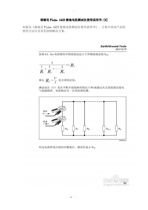
福禄克Fluke 1625接地电阻测试仪使用说明书:[5]本篇为《福禄克Fluke 1625接地电阻测试仪使用说明书》,主要介绍该产品的使用方法以及常见故障解决方案。
100 Ω精度±(读数的 2 % + 2 位数)操作误差±(读数的 5 % + 5 位数)测量时间通常为 6 秒最大干扰电压24 V,超过 24 V 无法启动测量最大过载U rms最大= 250 V电阻测量(R 直流)测量方法可按照 IEC61557-4 进行电流-电压测量测量电压20 V 直流电短路电流250 mA 直流电测量值的公式对于四极测量,可延长 H、S、ES 导线而不会产生附加误差。
导线 E 中的电阻 > 1 Ω时,可导致 5m Ω/Ω的附加误差。
测量范围0.020 Ω至 300 kΩ显示范围0.001 Ω至 2.999 Ω3.00 Ω至 29.99 Ω30.0 Ω至 299.9 Ω300 Ω至 2999 Ω3.0 kΩ至 29.99 kΩ30.0 kΩ至 299.9 kΩ分辨率0.001 Ω0.01 Ω0.1 Ω1 Ω10 Ω100 Ω精度±(读数的 2 % + 2 位数)操作误差±(读数的 5 % + 5 位数)测量序列约 2 次测量/秒测量时间通常为 4 秒,包括极性反转(二极或四极)最大干扰电压直流或交流电压≤3 V,超过 3 V 无法启动测量最大感应率 2 Henry最大过载U rms = 250 V导线电阻补偿 (R K)在 R [414]K在 R [416]E在 R [418]E在 R [420]测量值的公式R 显示屏 = R 测得 - R 补偿** 设定点输入值 RK = 0.000 Ω,通过调整测量在 0.000 至 29.99 Ω范围内变化。
无桩接地回路测量(双钳口,无桩)开关档位RA 四极(双钳口,无桩)分辨率0.001 Ω至 0.1 Ω测量范围0.02 Ω至 199.9 Ω精度±(读数的 7 % + 3 位数)操作误差±(读数的 10 % + 5 位数)测量电压Vm = 48 V 交流(初级电压)测量频率128 Hz噪声电流 (IEXT) 最大IEXT = 10 A(交流)(RA < 20 Ω)最大IEXT = 2 A(交流)(RA > 20 Ω)测量原理:使用两个电流互感器对闭合环路中的电阻进行无桩测量。
福禄克1523 1524参考测温仪说明书

1523/1524 参考测温仪一台工具即可测量三种传感器 并具备图形显示和记录功能技术数据您期待已久的通用型参考测温仪 - 像您一样的多面手福禄克计量校准部推出的 1523/1524 参考测温仪可测量 PRT 、热电偶及热敏电阻,并具图形显示和记录功能。
这两款测温仪读出器均具有精度高、量程宽的优点,还能记录读数和显示趋势图 - 这些可以四处携带的手持式工具堪称不折不扣的多面手。
1523/1524 让您轻松应对现场应用、实验室测量和数据记录任务。
另外,1524 型号的双通道测量功能让用户事半功倍。
无论何种场合, 总能精确、一致 地完成测量任务为了确保合规、获得优异的产量、出色的节能效果和稳定一致的结果,您需要准确无误的测量。
1523/1524 采用了只有高档仪表中才使用的电流反向技术,消除了热电动势 (EMF),可以精确测量温度数据。
各项技术指标均在 -10 ºC 至 60 ºC 的环境中有效。
特殊的精密电阻和高度稳定的参考电压源可以使 1523/1524 几乎不受外部环境温度的影响。
就像 Fluke 的所有手持工具一样, 1523/1524 参考测温仪也在极端温度和苛刻的振动条件下经过了严格的测试,用户可以放心地把它带到任何需要的地方。
您可使用磁性挂钩选件将仪表悬挂起来,既方便查看测量数据,又能腾出双手,专注于工作。
1523 25 • 1524:双通道;存储器可记录 15,000 条测量数据;带有用于生成日期和时间戳的实时时钟1 RS-232 串口连接器。
如需与 PC 通信,可从存储器和探头 INFO-CON 连接器上传和下载数据。
2 传感器连接器(PRT 、热电偶或热敏电阻)4 外部电源适配器插口,可持续使用仪表而无需更换电池。
或者,在现场可使用3 节 AA 电池持续供电 20 分钟。
1523 参考测温仪是一款多功能单通道测温仪,让用户通过一台工具便可测量三种传感器并具备测量数据绘图和记录功能。
福禄克 1742 1746和1748 在线可移动式电能质量记录仪 说明页 说明书

PN 4947664 November 2017 (Simplified Chinese)©2017 Fluke Corporation. All rights reserved.Specifications are subject to change without notification.All product names are trademarks of their respective companies.Fluke CorporationP.O. Box 9090 Everett, WA 98206-9090 U.S.A.Fluke Europe B.V.P.O. Box 11865602 BD EindhovenThe NetherlandsООО «ФлюкСИАЙЭС»125167, г. Москва,Ленинградскийпроспектдом 37,корпус 9, подъезд 4, 1 этаж174xIP65 Voltage Adapter使用说明书IP65 Voltage Adapter(以下简称“本产品”或“本适配器”)使174x Logger 系列能够在苛刻的环境中安全可靠地运行。
本适配器可密封和保护电压测量输入和电源端子,以免进水和进入灰尘。
如何联系 Fluke可通过以下电话号码联系 Fluke:•美国:1-800-760-4523•加拿大:1-800-36-FLUKE (1-800-363-5853)•巴西:+55-11-3530-8901•欧洲:+31 402-675-200•日本:+81-3-6714-3114•新加坡:+65-6799-5566•中国:+86-400-810-3435•世界任何地区:+1-425-446-5500访问以注册您的产品并获取更多信息。
要查看、打印或下载最新版的手册补遗,请访问/usen/support/manuals。
福禄克FLUKE过程校准仪使用使用说明
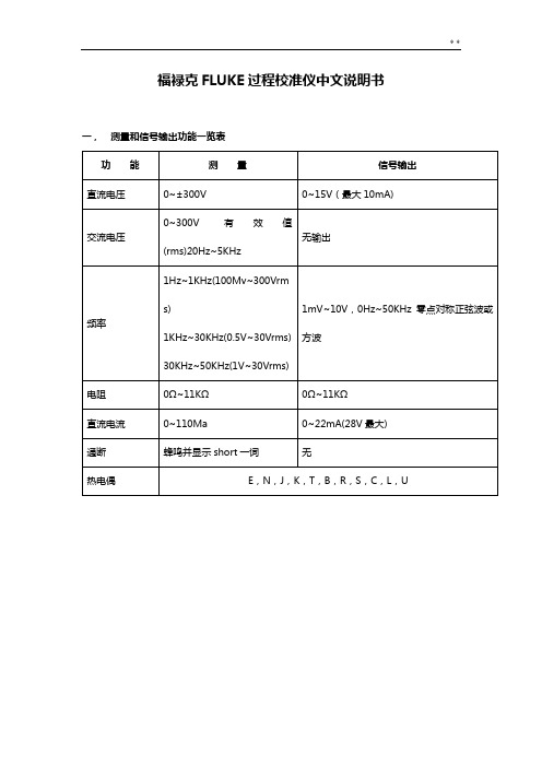
福禄克FLUKE过程校准仪中文说明书一,测量和信号输出功能一览表热电阻2,3,4线测量2线输出100ΩPlatinum(3926)100ΩPlatinum(385)120ΩNickel(672)200ΩPlatinum(385)500ΩPlatinum(385)1000ΩPlatinum(385)10ΩCopper(427)100ΩPlatinum(3916)压力27种压力模块从2.5kPa至69,000kPa *回路电压24或28V(22mA最大)*对于压力输出功能,是指由外部手动压力泵或其它压力源作为压力信号二、初识校准仪1.当你第一次取出校准仪,你需要将电池充电见图9,给电池充电2小时。
2.将电池放入校准仪中。
3.连接校准仪的电压输出端和输入端如下:连接最左端的一对插孔(V、Ω、RTD输出)和最右端的一对插孔(VMEAS)(见图3)。
图3 跨接线连接图4 输入输出的例子4.开机按⊙,按▲,▼以调整对比度。
以达到最好的显示效果。
校准仪在接通电源时是直流电压的测量功能,可以在一对VMEAS输入插孔中得到读数。
5.按看到其测量情况。
6.按V—…键,选择直流电压输出。
按数字键5和ENTER=开始输出5.0000V直流电压。
7.量直流电压。
你将在上半部屏幕看到测量读数,在下半部屏幕看到输出值,如图4所示。
三、操作功能1.输入和输出插孔图5所示,校准器输入和输出插孔,表2解释它的用途。
表2 输入/输出插孔和连接器7,8!SOURCE(输出)mA测量mAΩRTD插孔输出或测量电流、电阻和RTDS插孔,并提供回路电源9,10!SOURE(输出)V ΩRTD插孔输出电压、电阻、频率、和模拟RTDS输出插孔图5 输入/输出插孔和连接2.按键校准仪按键如图6所示,表3解释它们的功能,有4个未带标记的兰色按键,在显示屏幕下面称之为功能键。
其功能在操作过程中屏幕出现的定义所确定。
功能键和其显示内部在本手册中用黑体字标明,例如:Choices图6 按键表3 键的功能序号性能说明15 V-键测量方式中选择直流电压,输出方式中选择直流电压16 开关键电源开关3.显示屏幕图7为典型的显示屏幕。
福禄克 Fluke 317 319 真有效值交直流数字钳形表 说明书
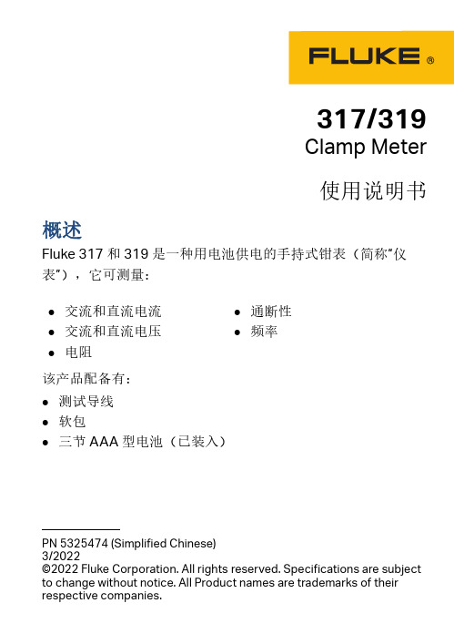
317/319Clamp Meter使用说明书概述Fluke 317 和 319 是一种用电池供电的手持式钳表(简称“仪表”),它可测量:该产品配备有:●测试导线●软包●三节 AAA 型电池(已装入)●交流和直流电流●交流和直流电压●电阻●通断性●频率PN 5325474 (Simplified Chinese)3/2022©2022 Fluke Corporation. All rights reserved. Specifications are subject to change without notice. All Product names are trademarks of their respective companies.2联系 FlukeFluke Corporation 在全球范围内运营。
如需获取本地联系信息,请访问我们的网站: 。
要注册您的产品或查看、打印、下载最新的手册或手册补遗,请访问我们的网站。
+1-425-446-5500 ********************安全须知警告表示可能对用户造成危险的状况和操作。
小心表示可能对产品或受测设备造成损坏的状况和操作。
警告为了防止可能发生的触电、火灾或人身伤害:●在使用产品前,请先阅读所有安全须知。
●仔细阅读所有说明。
●请勿改装本产品,并且只能将本产品用于指定用途,否则可能减弱本产品所提供的防护功能。
●若本产品不能正常工作,请勿使用。
●如果产品被改动或已损坏,请勿使用。
●请仅将产品用于指定用途,否则可能减弱产品提供的防护。
Fluke Corporation P.O. Box 9090Everett WA 98206-9090U.S.A.Fluke Europe B.V.P.O. Box 11865602 BD Eindhoven The Netherlands●请按照指定的测量类别、电压或电流额定值进行操作。
●请勿触摸电压超过 30 V 交流有效值、42 V 交流峰值或60V 直流的带电导体。
福禄克 Fluke a3002 FC 系列无线万用表 校准手册 说明书
a3002 FCWireless AC/DC Current ClampCalibration Manual August 2014© 2014 Fluke Corporation. All rights reserved. Specifications are subject to change without notice.All product names are trademarks of their respective companies.LIMITED WARRANTY AND LIMITATION OF LIABILITYEach Fluke product is warranted to be free from defects in material and workmanship under normal use and service. The warranty period is three years and begins on the date of shipment. Parts, product repairs, and services are warranted for 90 days. This warranty extends only to the original buyer or end-user customer of a Fluke authorized reseller, and does not apply to fuses, disposable batteries, or to any product which, in Fluke's opinion, has been misused, altered, neglected, contaminated, or damaged by accident or abnormal conditions of operation or handling. Fluke warrants that software will operate substantially in accordance with its functional specifications for 90 days and that it has been properly recorded on non-defective media. Fluke does not warrant that software will be error free or operate without interruption.Fluke authorized resellers shall extend this warranty on new and unused products to end-user customers only but have no authority to extend a greater or different warranty on behalf of Fluke. Warranty support is available only if product is purchased through a Fluke authorized sales outlet or Buyer has paid the applicable international price. Fluke reserves the right to invoice Buyer for importation costs ofrepair/replacement parts when product purchased in one country is submitted for repair in another country.Fluke's warranty obligation is limited, at Fluke's option, to refund of the purchase price, free of charge repair, or replacement of a defective product which is returned to a Fluke authorized service center within the warranty period.To obtain warranty service, contact your nearest Fluke authorized service center to obtain return authorization information, then send the product to that service center, with a description of the difficulty, postage and insurance prepaid (FOB Destination). Fluke assumes no risk for damage in transit. Following warranty repair, the product will be returned to Buyer, transportation prepaid (FOB Destination). If Fluke determines that failure was caused by neglect, misuse, contamination, alteration, accident, or abnormal condition of operation or handling, including overvoltage failures caused by use outside the product’s specified rating, or normal wear and tear of mechanical components, Fluke will provide an estimate of repair costs and obtain authorization before commencing the work. Following repair, the product will be returned to the Buyer transportation prepaid and the Buyer will be billed for the repair and return transportation charges (FOB Shipping Point).THIS WARRANTY IS BUYER'S SOLE AND EXCLUSIVE REMEDY AND IS IN LIEU OF ALL OTHER WARRANTIES, EXPRESS OR IMPLIED, INCLUDING BUT NOT LIMITED TO ANY IMPLIED WARRANTY OF MERCHANTABILITY OR FITNESS FOR A PARTICULAR PURPOSE. FLUKE SHALL NOT BE LIABLE FOR ANY SPECIAL, INDIRECT, INCIDENTAL OR CONSEQUENTIAL DAMAGES OR LOSSES, INCLUDING LOSS OF DATA, ARISING FROM ANY CAUSE OR THEORY.Since some countries or states do not allow limitation of the term of an implied warranty, or exclusion or limitation of incidental or consequential damages, the limitations and exclusions of this warranty may not apply to every buyer. If any provision of this Warranty is held invalid or unenforceable by a court or other decision-maker of competent jurisdiction, such holding will not affect the validity or enforceability of any other provision.Fluke CorporationP.O. Box 9090 Everett, WA 98206-9090 U.S.A. Fluke Europe B.V. P.O. Box 1186 5602 BD Eindhoven The Netherlands11/99Table of ContentsPage TitleIntroduction (1)Contact Fluke (1)Safety Information (2)Symbols (3)Specifications (4)Required Equipment (5)Performance Tests (6)Test the Display (6)Backlight (7)Keypad Test (7)Current Test (7)Before Calibration Adjustment (9)Maintenance Mode (9)Password Entry (9)Change the Password (9)Restore the Default Password (10)Calibration Adjustment (11)Maintenance (12)Clean the Product (12)Battery Replacement (12)User-Replaceable Parts (13)ia3002 FCCalibration ManualiiList of TablesTable Title Page ..................................................................................................................31. SymbolsEquipment (5)2. Required7.................................................................................................3. PerformanceTestsAdjustment (11)4. Calibration5. User-Replaceable Parts (13)iiia3002 FCCalibration ManualivvList of FiguresFigure Title Page1. All Segments of the Display (6)2. Performance Test and Calibration Connections (8)3. Calibration Password Reset (10)4. Battery Replacement (13)a3002 FCCalibration ManualviIntroductionWarningRead "Safety Information" before you use the Product.This manual has the verification and calibration adjustment procedures for thea3002 FC Wireless AC/DC Current Clamp (the Product). Please see thea3002 FC AC/DC Current Clamp Quick Reference Guide for usage information. Contact FlukeTo contact Fluke, call one of the following telephone numbers:•Technical Support USA: 1-800-44-FLUKE (1-800-443-5853)•Calibration/Repair USA: 1-888-99-FLUKE (1-888-993-5853)•Canada: 1-800-36-FLUKE (1-800-363-5853)•Europe: +31 402-675-200• Japan: +81-3-6714-3114• Singapore: +65-6799-5566•Anywhere in the world: +1-425-446-5500Or, visit Fluke's website at .To register your product, visit .To view, print, or download the latest manual supplement, visit/usen/support/manuals.1a3002 FC Calibration Manual2 Safety InformationA Warning identifies conditions and procedures that are dangerous to the user.A Caution identifies conditions and procedures that can cause damage to theProduct or the equipment under test.WarningTo prevent possible electrical shock, fire, or personal injury:•Carefully read all instructions.•Use the Product only as specified, or the protectionsupplied by the Product can be compromised.•Limit operation to the specified measurement category,voltage, or amperage ratings.•Do not touch voltages > 30 V ac rms, 42 V ac peak, or60 V dc.•Do not use the Product around explosive gas, vapor, or indamp or wet environments.•Do not use the Product if it is damaged.•Disable the Product if it is damaged.•Do not use the Product if it operates incorrectly.•The battery door must be closed and locked before youoperate the Product.•Replace the batteries when the low battery indicator showsto prevent incorrect measurements.•Have an approved technician repair the Product.•Use only specified replacement parts.•Do not connect directly to mains.For safe operation and maintenance of the Product:•Remove batteries to prevent battery leakage and damage tothe Product if it is not used for an extended period.•Repair the Product before use if the battery leaks.•Be sure that the battery polarity is correct to prevent batteryleakage.•Batteries contain hazardous chemicals that can cause burns or explode. If exposure to chemicals occurs, clean withwater and get medical aid.Symbols SymbolsThe symbols in Table 1 are used on the Product or in this manual.Table 1. SymbolsSymbol MeaningRisk of Danger. Important information. See Manual.Hazardous voltageDouble insulationBatteryConforms to relevant South Korean EMC standards.CAT III Measurement Category III is applicable to test and measuring circuits connected to the distribution part of the building’s low-voltage MAINS installation.CAT IV Measurement Category IV is applicable to test and measuring circuits connected at the source of the building’s low-voltage MAINS installation.Conforms to European Union directives.Conforms to relevant North American Safety Standards. Conforms to relevant Australian EMC requirements.This product complies with the WEEE Directive (2002/96/EC) marking requirements. The affixed label indicates that you must not discard this electrical/electronic product in domestic household waste. Product Category: With reference to the equipment types in the WEEE Directive Annex I, this product is classed as category 9 "Monitoring and Control Instrumentation” product. Do not dispose of this product as unsorted municipal waste. Go to Fluke’s website for recycling information.Calibration ManualSpecificationsRangeA dc ................................................................. 1000 AA ac ................................................................. 600.0 AResolutionA dc ................................................................. 0.1 AA ac ................................................................. 0.1 AAccuracyA dc ................................................................. (0.5% + 3 counts)A ac ................................................................. (1.0% + 3 counts) from 45 Hz to 1000 HzLCD w/Backlight.................................................... 3 ½ digitsLog Rate/Interval................................................... 1 second to 1 hour adjustable by PC, default, 1 minuteBattery Type .......................................................... 2 AA, NEDA 15 A, IEC LR6Battery Life ............................................................ 400 hoursMemory .................................................................. Record a maximum of 65,000 readingsRadio Frequency Communications .................... 2.4 GHz ISM BandRadio Frequency Communication Range .......... 20 m (65.61 ft)Radio Frequency Certification............................. FCC: T68-DMFBLE; IC: 6627A-DMFBLEOperating Temperature ........................................ -10 °C to +50 °C (14 °F to 122 °F)Storage Temperature............................................ -40 °C to +60 °C (-40 °F to 140 °F)Operating Humidity............................................... 90 % from 0 °C to 35 °C, 45 % to 40 °C, 45 % to 50 °C(90 % from 32 °F to 95 °F, 45 % to 104 °F, 45 % to 122 °F)Operating Altitude................................................. 2,000 m (6,562 ft)Storage Altitude .................................................... 12,000 m (39,370 ft)Ingress Protection (IP) rating............................... IP42Safety ..................................................................... IEC 61010-1, Pollution Degree 2Electromagnetic Environment............................. IEC 61236-1, PortableElectromagnetic Compatibility ............................ Radio Frequency Emissions, IEC CISPR 11: Group 1, Class A.Group 1 have intentionally generated and/or use conductively coupledradio-frequency energy which is necessary for the internal functioningof the equipment itself.Class A equipment is suitable for use in non-domestic locations and/ordirectly connected to a low-voltage power supply network. Class Aequipment may have potential difficulties in ensuring electromagneticcompatibility in other environments due to conducted as well asradiated disturbances.Applies to use in Korea only. .............................. Class A Equipment (Industrial Broadcasting & CommunicationEquipment) [1][1] This product meets requirements for industrial (Class A) electromagneticwave equipment and the seller or user should take notice of it. Thisequipment is intended for use in business environments and is not to beused in homes.Temperature Coefficient....................................... Add 0.1 X (specified accuracy)/ °C (<18 °C or >28 °C)Add 0.1 X (specified accuracy)/ °F (<64.4 °F or >82.4 °F) Size......................................................................... 160 mm x 66 mm x 38 mm (6.3 in x 2.6 in x 1.5 in)Weight.................................................................... 0.255 kg (9 oz)Required Equipment Required EquipmentThe equipment in Table 2 is necessary for performance tests and calibrationadjustment.Table 2. Required EquipmentRecommended Equipment Function Required CharacteristicsFluke 5522A Calibrator (or equivalent) AC Volts6 mV to 600 V±0.25 % @ 45 Hz to 1 kHz DC Volts 0 V to ±1000 V ±0.1 %Calibration ManualPerformance TestsWarningTo prevent possible electrical shock, fire, or personal injury,do not perform the performance test procedures unless theProduct is fully assembled.The performance tests verify the full operation of the Product and measure theaccuracy of each function against Product specifications. If the Product fails apart of the test, calibration adjustment and/or repair is necessary. See“Calibration Adjustment”.Test the DisplayTo verify that all segments of the display function:1. With the Product OFF, push and hold .2. Push while you keep pushed until all of the display segments areshown. See Figure 1.hby002.epsFigure 1. All Segments of the DisplayIf segments of the display are missing, repair is necessary. See “ContactFluke”.Performance TestsBacklightTo verify that the backlight functions:1. With the Product ON, push .2. The backlight will come on. If it does not, repair is necessary. See “ContactFluke”.Keypad TestTo verify that the keypad functions, turn ON the Product and push each buttonseparately. Each button push will turn on a display annunciator, and will turnon the backlight. If the buttons do nothing, repair is necessary. See “ContactFluke”.Current TestBefore you do the current test:1. Make sure that you have the necessary equipment. See Table2.2. Make sure the Product battery is good and replace it if necessary. See“Battery Replacement”.3. Warm up the Calibrator as necessary. Refer to its specifications.4. Let the temperature of the UUT become stable to room temperature.To do the current test:1. Connect the Calibrator volts output and ground to the Product. See Figure2.2. Apply the input level for each step shown in Table3.3. Compare the indication on the Product display with the UUT reading limits inTable 3.4. If the display indication falls outside of the range shown in Table 3, calibrationadjustment or repair of the Product is necessary. See “CalibrationAdjustment”.Table 3. Performance TestsTest CalibratorInput Resolution Specification UUT Reading LimitUnit Low HighAC mV6.0 mV,45 Hz0.1 ±[1.0 %, 3 digits]5.66.4 ACA6.0 mV,1000 Hz 5.6 6.4 600.0 mV,45 Hz 593.7 606.3 600.0 mV,1000 Hz 593.7 606.3DC mV 980.0 mV, 0 Hz±[0.5 %, 3 digits] 974.8 985.2 DCA0.0 mV, 0 Hz -0.3 0.3-980.0 mV, 0 Hz -985.2 -974.8Calibration ManualFigure 2. Performance Test and Calibration ConnectionsBefore Calibration Adjustment Before Calibration AdjustmentBefore the Product calibration can be adjusted, you must go through themaintenance mode menu and enter your password.Maintenance ModeThe Product maintenance mode can be used to set different parameters on theProduct that include auto power off, backlight adjustment, and calibration. To usethe maintenance mode:1. With the Product OFF, push and hold .2. Push . Keep pushed until all the display segments are shown.3. Release and .The Product is now in maintenance mode.Password EntryTo go to the calibration mode, push until CAL is shown. You will need toenter a password to access calibration mode.To enter the password:1. Push and the CAL count is shown. For example n002.2. Push to show “”. The first “?” flashes.3. Push to change the flashing “?” to the first digit of your password(default: 1234).4. Push to confirm your choice. The subsequent “?” flashes.5. Do steps 3 and 4 again to enter the subsequent digits of the four-numberpassword.6. When all of the correct digits are entered, push to confirm the input.If the correct password is entered, “C-01” is shown. If the incorrect passwordis entered, “” is shown and the password must be correctly entered togo to the first calibration point, “C-01”.Change the PasswordNoteIf you change the password and then lose it, see the “Restore theDefault Password” section.To change the password:1. Do steps 1 through 5 in the “Password Entry” section.2. Before you push to confirm your final input (step 6), push to show “----”on the display. The first “-” flashes.3. Push to change the first “-” to the first digit of your new password.4. Push to confirm your choice. The next “-” flashes.5. Repeat steps 3 and 4 to enter the subsequent digits of the new four-numberpassword.6. When the correct digits are entered, push to confirm the input and changethe password. If the Product has been calibrated, it will go to normalmeasurement mode, or it will show “donE”.Calibration ManualRestore the Default PasswordIf the calibration password is lost, the default password (1234) can be manuallyrestored with the subsequent steps:WarningTo prevent electric shock or personal injury, remove all inputsignals before you open the Product.1. Remove the Product battery door. See “Battery Replacement”.2. With a Phillips screwdriver, remove the bottom case screws. Two of thescrews are inside of the battery door.3. Keep the pca in the top case.4. Apply 3.0 V across the battery contacts on the pca. Note the polarity that isshown in Figure 3.5. Push on the front of the Product.6. Short across the CAL keypad on the pca. See Figure 3. The default passwordis now restored.7. Remove the 3.0 V supply and replace the bottom case, batteries, and batterydoor.Figure 3. Calibration Password ResetCalibration Adjustment Calibration AdjustmentThe Product features closed-case calibration adjustment and uses knownreference sources. The Product measures the applied reference source,calculates correction factors, and stores the correction factors in nonvolatilememory.Should the Product fail any of the performance tests, do the calibrationadjustment procedure.When “C-01” is shown on the display, apply the correct input signal shown inTable 4 to the Product. Then push to confirm the calibration step. If the inputsignal does not satisfy the calibration requirement, “Err” is shown. If the signal isnot stable, it can be necessary to push several times to confirm the calibration.After confirmation, the Product goes to the subsequent calibration step.NoteAfter you push , wait until the calibration step number advancesbefore you change the calibrator source. Some adjustment stepscan take several seconds to execute before the Product goes to thesubsequent step.Set the Calibrator to Standby after you complete adjustment of eachfunction.Input each signal to the Product in the sequence shown in Table 4. When the lastcalibration point is recorded, “End” shows on the display.NoteWhile the calibration adjustment points are shown in Table 4, theProduct also can show the necessary inputs. For each step, pushto see the necessary current input and then push to see thenecessary frequency input.Table 4. Calibration AdjustmentCalibration Step Calibrator Output SignalC-01 6.0 mV, 55 HzC-02 60.0 mV, 55 HzC-03 600.0 mV, 55 HzC-04 1000.0 mV, 0 HzCalibration ManualMaintenanceClean the ProductCautionTo prevent possible damage to the Product or to equipmentunder test, do not use abrasive cleaners. They will damage thecase.To clean the Product, use a cloth with a mild cleaning solution.Battery ReplacementWarningTo prevent possible explosion, fire, or personal injury, Replacethe batteries when the low battery indicator ( ) shows toprevent incorrect measurements.CautionTo prevent possible damage to the Product or to equipmentunder test:•Remove batteries to prevent battery leakage and damage tothe Product if it is not used for an extended period.•Be sure that the battery polarity is correct to prevent batteryleakage.To change the batteries, see Figure 4:1. Make sure the Product is OFF.2. Turn over the Product to access the battery compartment door screw.3. Use a flat-head screwdriver to loosen the battery compartment door screwand lift off the battery compartment door.4. Replace the two AA batteries. Make sure to use the correct polarity when youput the batteries into the battery compartment door.5. Reattach the battery compartment door.6. Tighten the battery compartment door screw.Wireless AC/DC Current ClampUser-Replaceable PartsFigure 4. Battery ReplacementUser-Replaceable PartsUser-replaceable parts are shown in Table 5.Table 5. User-Replaceable PartsFluke Part Number Description Qty4108300 FLK-A3000-2003, DOOR, BATTERY 1376756 Battery, AA 1.5 V, NEDA 15 A, IEC LR6 24466484 INFORMATION PACK, FLK-A3002 FC 113a3002 FC Calibration Manual 14。
福禄克 Fluke a3001 FC 系列无线万用表 校准手册 说明书
a3001 FCWireless iFlexCalibration Manual August 2014© 2014 Fluke Corporation. All rights reserved. Specifications are subject to change without notice.All product names are trademarks of their respective companies.LIMITED WARRANTY AND LIMITATION OF LIABILITYEach Fluke product is warranted to be free from defects in material and workmanship under normal use and service. The warranty period is three years and begins on the date of shipment. Parts, product repairs, and services are warranted for 90 days. This warranty extends only to the original buyer or end-user customer of a Fluke authorized reseller, and does not apply to fuses, disposable batteries, or to any product which, in Fluke's opinion, has been misused, altered, neglected, contaminated, or damaged by accident or abnormal conditions of operation or handling. Fluke warrants that software will operate substantially in accordance with its functional specifications for 90 days and that it has been properly recorded on non-defective media. Fluke does not warrant that software will be error free or operate without interruption.Fluke authorized resellers shall extend this warranty on new and unused products to end-user customers only but have no authority to extend a greater or different warranty on behalf of Fluke. Warranty support is available only if product is purchased through a Fluke authorized sales outlet or Buyer has paid the applicable international price. Fluke reserves the right to invoice Buyer for importation costs ofrepair/replacement parts when product purchased in one country is submitted for repair in another country.Fluke's warranty obligation is limited, at Fluke's option, to refund of the purchase price, free of charge repair, or replacement of a defective product which is returned to a Fluke authorized service center within the warranty period.To obtain warranty service, contact your nearest Fluke authorized service center to obtain return authorization information, then send the product to that service center, with a description of the difficulty, postage and insurance prepaid (FOB Destination). Fluke assumes no risk for damage in transit. Following warranty repair, the product will be returned to Buyer, transportation prepaid (FOB Destination). If Fluke determines that failure was caused by neglect, misuse, contamination, alteration, accident, or abnormal condition of operation or handling, including overvoltage failures caused by use outside the product’s specified rating, or normal wear and tear of mechanical components, Fluke will provide an estimate of repair costs and obtain authorization before commencing the work. Following repair, the product will be returned to the Buyer transportation prepaid and the Buyer will be billed for the repair and return transportation charges (FOB Shipping Point).THIS WARRANTY IS BUYER'S SOLE AND EXCLUSIVE REMEDY AND IS IN LIEU OF ALL OTHER WARRANTIES, EXPRESS OR IMPLIED, INCLUDING BUT NOT LIMITED TO ANY IMPLIED WARRANTY OF MERCHANTABILITY OR FITNESS FOR A PARTICULAR PURPOSE. FLUKE SHALL NOT BE LIABLE FOR ANY SPECIAL, INDIRECT, INCIDENTAL OR CONSEQUENTIAL DAMAGES OR LOSSES, INCLUDING LOSS OF DATA, ARISING FROM ANY CAUSE OR THEORY.Since some countries or states do not allow limitation of the term of an implied warranty, or exclusion or limitation of incidental or consequential damages, the limitations and exclusions of this warranty may not apply to every buyer. If any provision of this Warranty is held invalid or unenforceable by a court or other decision-maker of competent jurisdiction, such holding will not affect the validity or enforceability of any other provision.Fluke CorporationP.O. Box 9090 Everett, WA 98206-9090 U.S.A. Fluke Europe B.V. P.O. Box 1186 5602 BD Eindhoven The Netherlands11/99Table of ContentsPage TitleIntroduction (1)Contact Fluke (1)Safety Information (2)Symbols (3)Specifications (4)Required Equipment (5)Performance Tests (5)Test the Display (5)Backlight (6)Keypad Test (6)AC Current Test (6)Before Calibration Adjustment (9)Maintenance Mode (9)Password Entry (9)Change the Password (9)Restore the Default Password (10)Calibration Adjustment (11)Maintenance (12)Clean the Product (12)Battery Replacement (12)User-Replaceable Parts (13)ia3001 FCCalibration ManualiiList of TablesTable Title Page ..................................................................................................................31. SymbolsEquipment (5)2. Required7.................................................................................................3. PerformanceTestsAdjustment (11)4. Calibration5. User-Replaceable Parts (13)iiia3001 FCCalibration ManualivList of FiguresTitle Page Figure1. All Segments of the Display (5)Connections for Simulated Voltages (7)Test2. PerformanceConnections for Applied Current (8)3. PerformanceTest4. Calibration Password Reset (10)..............................................................................................13Replacement5. Batteryva3001 FCCalibration ManualviIntroductionWarningRead "Safety Information" before you use the Product.This manual has the verification and calibration adjustment procedures for thea3001 FC Wireless iFlex (the Product). Please see the a3001 FC QuickReference Guide for usage information.Contact FlukeTo contact Fluke, call one of the following telephone numbers:•Technical Support USA: 1-800-44-FLUKE (1-800-443-5853)•Calibration/Repair USA: 1-888-99-FLUKE (1-888-993-5853)•Canada: 1-800-36-FLUKE (1-800-363-5853)•Europe: +31 402-675-200• Japan: +81-3-6714-3114• Singapore: +65-6799-5566•Anywhere in the world: +1-425-446-5500Or, visit Fluke's website at .To register your product, visit .To view, print, or download the latest manual supplement, visit/usen/support/manuals.1a3001 FC Calibration Manual2 Safety InformationA Warning identifies conditions and procedures that are dangerous to the user.A Caution identifies conditions and procedures that can cause damage to theProduct or the equipment under test.WarningTo prevent possible electrical shock, fire, or personal injury:•Carefully read all instructions.•Use the Product only as specified, or the protectionsupplied by the Product can be compromised.•Limit operation to the specified measurement category,voltage, or amperage ratings.•Do not touch voltages > 30 V ac rms, 42 V ac peak, or 60 Vdc.•Do not use the Product around explosive gas, vapor, or indamp or wet environments.•Do not use the Product if it is damaged.•Disable the Product if it is damaged.•Do not use the Product if it operates incorrectly.•The battery door must be closed and locked before youoperate the Product.•Replace the batteries when the low battery indicator showsto prevent incorrect measurements.•Have an approved technician repair the Product.•Use only specified replacement parts.•Comply with local and national safety codes. Use personalprotective equipment (approved rubber gloves, faceprotection, and flame-resistant clothes) to prevent shockand arc blast injury where hazardous live conductors areexposed.•Do not work alone.•Before each use, examine the Product. Look for cracks ormissing pieces of the clamp housing or output cableinsulation. Also look for loose or weakened components.Carefully examine the insulation around the jaws.•De-energize the circuit or wear personal protectiveequipment in compliance with local requirements beforeyou apply or remove the Flexible Current Probe.•Do not operate the Product with covers removed or the caseopen. Hazardous voltage exposure is possible.•Remove the input signals before you clean the Product.SymbolsFor safe operation and maintenance of the Product:•Remove batteries to prevent battery leakage and damage tothe Product if it is not used for an extended period.•Repair the Product before use if the battery leaks.•Be sure that the battery polarity is correct to prevent batteryleakage.•Batteries contain hazardous chemicals that can causeburns or explode. If exposure to chemicals occurs, cleanwith water and get medical aid.SymbolsThe symbols in Table 1 are used on the Product or in this manual.Table 1. SymbolsSymbol MeaningRisk of Danger. Important information. See Manual.Hazardous voltageDouble insulationBatteryConforms to relevant South Korean EMC standards.CAT III Measurement Category III is applicable to test and measuring circuits connected to the distribution part of the building’s low-voltage MAINS installation.CAT IV Measurement Category IV is applicable to test and measuring circuits connected at the source of the building’s low-voltage MAINS installation.Conforms to European Union directives.Conforms to relevant North American Safety Standards. Conforms to relevant Australian EMC requirements.This product complies with the WEEE Directive (2002/96/EC) marking requirements. The affixed label indicates that you must not discard this electrical/electronic product in domestic household waste. Product Category: With reference to the equipment types in the WEEE Directive Annex I, this product is classed as category 9 "Monitoring and Control Instrumentation” product. Do not dispose of this product as unsorted municipal waste. Go to Fluke’s website for recycling information.Calibration ManualSpecificationsRange..................................................................... 2500 A acResolution ............................................................. 0.1 A for 0 A to 1000 A; 1 A for 1000 A to 2500 AAccuracy................................................................ 3 % ±5 digits (45 Hz to 500 Hz)Crest Factor (50 Hz/60 Hz).................................... 3.0 at 1100 A, 2.5 at 1400 A, 1.42 at 2500 A, add 2 % for C.F. >2Frequency.............................................................. 45 to 500 Hz 0.5 % ±5 digitsLCD w/Backlight.................................................... 3 ½ digitsLog Rate/Interval................................................... 1 second to 1 hour adjustable by PC, default, 1 minuteBattery Type .......................................................... 2 AA, NEDA 15 A, IEC LR6Battery Life ............................................................ 370 hoursMemory .................................................................. Record a maximum of 65,000 readingsRadio Frequency Communications .................... 2.4 GHz ISM BandRadio Frequency Communication Range .......... 20 m (65.61 ft)Radio Frequency Certification............................. FCC: T68-FBLE; IC: 6627A-FBLEOperating Temperature ........................................ -10 °C to +50 °C (14 °F to 122 °F)Storage Temperature............................................ -40 °C to +60 °C (-40 °F to 140 °F)Operating Humidity............................................... 90 % at 35 °C, 75 % at 40 °C, 45 % at 50 °C(90 % at 95 °F, 75 % at 104 °F, 45 % at 122 °F)Operating Altitude................................................. 2,000 m (6,562 ft)Storage Altitude .................................................... 12,000 m (39,370 ft)Temperature Coefficien t ....................................... Add 0.1 X (specified accuracy)/ °C (<18 °C or >28 °C)Add 0.1 X (specified accuracy)/ °F (<64.4 °F or >82.4 °F) Safety ..................................................................... IEC 61010-1, Pollution Degree 2Electromagnetic Environment............................. IEC 61236-1, PortableElectromagnetic Compatibility ............................ Radio Frequency Emissions, IEC CISPR 11: Group 1, Class A.Group 1 have intentionally generated and/or use conductively coupledradio-frequency energy which is necessary for the internal functioningof the equipment itself.Class A equipment is suitable for use in non-domestic locations and/ordirectly connected to a low-voltage power supply network. Class Aequipment may have potential difficulties in ensuring electromagneticcompatibility in other environments due to conducted as well asradiated disturbances.Applies to use in Korea only. .............................. Class A Equipment (Industrial Broadcasting & CommunicationEquipment) [1][1] This product meets requirements for industrial (Class A) electromagneticwave equipment and the seller or user should take notice of it. Thisequipment is intended for use in business environments and is not to beused in homes.Ingress Protection (IP) rating............................... IP42Size......................................................................... 165 mm x 64 mm x 36 mm (6.5 in x 2.5 in x 1.4 in)Weight.................................................................... 0.283 kg (10 oz)Jaw Opening.......................................................... 10 in coilPerformance TestsRequired EquipmentThe equipment in Table 2 is necessary for performance tests and calibrationadjustment.Table 2. Required EquipmentEquipment Required Characteristics Recommended ModelCalibrator 4.5-digit resolutionDC Current Accuracy:600 μA to 20 A ±0.25 %Fluke 5522A Calibrator(or equivalent)Wired coil 50 turns 5500A/COILTest Probe for iFlex 2 mm to 4 mm Slim Reach Probe TP2, PN 650892Test Lead Test Lead with retractable sheath 6358, PN1903307Performance TestsWarningTo prevent possible electrical shock, fire, or personal injury,do not perform the performance test procedures unless theProduct is fully assembled.The performance tests verify the full operation of the Product and measure theaccuracy of each function against Product specifications. If the Product fails apart of the test, calibration adjustment and/or repair is necessary. See“Calibration Adjustment”.Test the DisplayTo verify that all segments of the display function:1. With the Product off, push and hold .2. Push while you keep pushed until all of the display segments areshown. See Figure 1.hby002.epsFigure 1. All Segments of the DisplayIf segments of the display are missing, repair is necessary. See “Contact Fluke”.Calibration ManualBacklightTo verify that the backlight functions:1. With the Product on, push .2. The backlight will come on. If it does not, repair is necessary. See “ContactFluke”.Keypad TestTo verify that the keypad functions, turn on the Product and push each buttonseparately. Each button push will turn on a display annunciator and will turnon the backlight. If the buttons do nothing, repair is necessary. See “ContactFluke”.AC Current TestBefore you do the ac current test:1. Make sure that you have the necessary equipment. See Table2.2. Make sure the Product battery is good and replace it if necessary. See“Battery Replacement”.3. Warm up the Calibrator as necessary. Refer to its specifications.4. Let the temperature of the unit under test (UUT) become stable to roomtemperature.To do the ac current test:1. Connect the Calibrator to one of the three Test Connections, as called out inTable 3.2. Apply the input level for each step shown in Table3.3. Compare the indication on the Product display with the UUT reading limits inTable 3.4. If the display indication falls outside of the range shown in Table 3, calibrationadjustment or repair of the Product is necessary. See “CalibrationAdjustment”.Performance Tests Table 3. Performance TestsTest ConnectionCalibratorOutput ValueRes. Spec.UUT Reading LimitLow HighSingle-Turn Loop 0 A,0 Hz0.13.0 % ±5 digits 00.5Single-Turn Loop 10 A,45 Hz0.19.210.8 50-Turn Coil 12 A,45 Hz0.1581.5618.5 50-Turn Coil 20 A,45 Hz19651035 Simulate 67.5 mV,45 Hz124202580 Single-Turn Loop 10 A,500 Hz0.19.210.8 Simulate 180 mV,500 Hz0.1581.5618.5 Simulate 300 mV,500 Hz19651035 Simulate 750 mV,500 Hz12420258050-Turn Coil45 Hz,0.4 A0.10.5% ±5 digits 44.345.750-Turn Coil500 Hz,0.325 A0.1497.0503.0Figure 2. Performance Test Connections for Simulated VoltagesCalibration ManualFigure 3. Performance Test Connections for Applied CurrentBefore Calibration Adjustment Before Calibration AdjustmentBefore the Product calibration can be adjusted, you must go through themaintenance mode menu and enter your password.Maintenance ModeThe Product maintenance mode can be used to set different parameters on theProduct that include auto power off, backlight adjustment, and calibration. To usethe maintenance mode:1. With the Product off, push and hold .2. Push . Keep pushed until all the display segments are shown.3. Release and .The Product is now in maintenance mode.Password EntryTo go to the calibration mode, push until CAL is shown. You will need toenter a password to access calibration mode.To enter the password:1. Push and the CAL count is shown. For example n002.2. Push to show “”. The first “?” flashes.3. Push to change the flashing “?” to the first digit of your password(default: 1234).4. Push to confirm your choice. The subsequent “?” flashes.5. Do steps 3 and 4 again to enter the subsequent digits of the four-numberpassword.6. When all of the correct digits are entered, push to confirm the input.If the correct password is entered, “C-01” is shown. If the incorrect passwordis entered, “” is shown and the password must be entered correctly togo to the first calibration point, “C-01”.Change the PasswordNoteIf you change the password and then lose it, see the “Restore theDefault Password” section.To change the password:1. Do steps 1 through 5 in the “Password Entry” section.2. Before you push to confirm your final input (step 6), push to show “----”on the display. The first “-” flashes.3. Push to change the first “-” to the first digit of your new password.4. Push to confirm your choice. The next “-” flashes.5. Repeat steps 3 and 4 to enter the subsequent digits of the new four-numberpassword.6. When the correct digits are entered, push to confirm the input and changethe password. If the Product has been calibrated, it will go to normalmeasurement mode, or it will show “donE”.Calibration ManualRestore the Default PasswordIf the calibration password is lost, the default password (1234) can be manuallyrestored with the subsequent steps:WarningTo prevent electric shock or personal injury, remove all inputsignals before you open the Product.1. Remove the Product battery door. See “Battery Replacement”.2. With a Phillips screwdriver, remove the bottom case screws. Two of thescrews are inside of the battery door.3. Keep the pca in the top case.4. Apply 3.0 V across the battery contacts on the pca. Note the polarity that isshown in Figure 4.5. Push on the front of the Product.6. Short across the CAL keypad on the pca. See Figure 4. The default passwordis now restored.7. Remove the 3.0 V supply and replace the bottom case, batteries, and batterydoor.Figure 4. Calibration Password ResetCalibration Adjustment Calibration AdjustmentThe Product features closed-case calibration adjustment and uses knownreference sources. The Product measures the applied reference source,calculates correction factors, and stores the correction factors in nonvolatilememory.Should the Product fail any of the performance tests, do the calibrationadjustment procedure.When “C-01” is shown on the display, apply the correct input signal shown inTable 4 to the Product. Then push to confirm the calibration step. If the inputsignal does not satisfy the calibration requirement, “Err” is shown. If the signal isnot stable, it can be necessary to push several times to confirm the calibration.After confirmation, the Product goes to the subsequent calibration step.NoteAfter you push , wait until the calibration step number advancesbefore you change the calibrator source. Some adjustment stepscan take several seconds to execute before the Product goes to thesubsequent step.Set the Calibrator to Standby after you complete adjustment of eachfunction.Input each signal to the Product in the sequence shown in Table 4. When the lastcalibration point is recorded, “End” shows on the display.NoteWhile the calibration adjustment points are shown in Table 4, theProduct also can show the necessary inputs. For each step, pushto see the necessary ac reference signal amplitude and thenpush to see the necessary frequency input. For this calibrationadjustment, volts are used in place of current. Use the connectionsshown in Figure 2.Table 4. Calibration AdjustmentCalibration Step Calibrator Output SignalC-01 1.35 mV, 45 HZC-02 5.4 mV, 45 HZC-03 16.2 mV, 45 HZC-04 4.05 mV, 45 HZC-05 12.15 mV, 135 HZC-06 20.25 mV, 225 HZC-07 32.4 mV, 360 HZC-08 44.55 mV, 495 HZCalibration ManualMaintenanceClean the ProductCautionTo prevent possible damage to the Product or to equipmentunder test, do not use abrasive cleaners. They will damage thecase.To clean the Product, use a cloth with a mild cleaning solution.Battery ReplacementWarningTo prevent possible explosion, fire, or personal injury, replacethe batteries when the low battery indicator ( ) shows toprevent incorrect measurements.CautionTo prevent possible damage to the Product or to equipmentunder test:•Remove batteries to prevent battery leakage and damage tothe Product if it is not used for an extended period.•Be sure that the battery polarity is correct to prevent batteryleakage.To change the batteries, see Figure 5:1. Make sure the Product is off.2. Turn over the Product to access the battery compartment door screw.3. Use a Phillips screwdriver to loosen the battery compartment door screw andlift off the battery compartment door.4. Replace the two AA batteries. Make sure to use the correct polarity when youput the batteries into the battery compartment door.5. Reattach the battery compartment door.6. Tighten the battery compartment door screw.Wireless iFlexUser-Replaceable PartsFigure 5. Battery ReplacementUser-Replaceable PartsUser-replaceable parts are shown in Table 5.Table 5. User-Replaceable PartsFluke Part Number Description Qty4130305 FLK-3000-2003, DOOR, BATTERY 13676410 FLUKE-I2500-10, IFLEX 2500A PROBE 10IN 11881997 TPAK, meter hanging kit 14466358 INFORMATION PACK,FLK-A3001 FC 1376756 Battery, AA 1.5 V, NEDA 15 A, IEC LR6 213a3001 FC Calibration Manual 14。
福禄克 Fluke 323真有效值钳型表 安全须知 说明书
323/324/325Clamp Meters安全说明书访访 以注册您的产品并获取更多信息。
警告表示可能对用户造成危险的状况和操作。
警告为了防止可能发生的触电、火灾或人身伤害:•请请格按照手册说明使用产品,否则可能减弱产品提供的防护。
•仅使用正确的测量标准类类 (CAT)、电电和电流额定探头、测测测测和适配器进行测量。
•交流电电真有效值高于 30 V、交流电电峰值高于42 V 或直流电电高于 60 V 时,请勿触摸。
•仔细细细所有说明。
•将手握于产品的安全触摸壁后面。
•请勿超出产品、探针或附件中额定值最低的单个元件的测量类类 (CAT) 额定值。
•测测测测位于输入插孔时,请勿测量电流。
•请勿在爆炸性气体、蒸汽周围或在潮湿环境中使用产品。
•应按照指定的测量类类、电电或电流额定值使用。
•不要单独工作。
•端子间或每个端子与接地点之间施加的电电不能超过额定值。
•遵守当地和国家的安全规范。
穿戴个人防护用品(经认可的橡胶手套、面具和阻燃衣物等),以防危险险电测体裸露时遭受电电和电弧而受伤。
•当显示电池电量不足指示时请更换电池,以防测量不正确。
•操作本产品前请确保电池盖关闭且锁定。
•先测量一个已知电电,以确定产品运行正常。
•移除测量不需要的所有探头、测测测和附件。
PN 4637516 (Simplified Chinese) March 2015© 2015 Fluke Corporation. All rights reserved.•请仅使用与仪器具有相同测量类类和额定电电的探头、测测测测和附件。
•请将手指握在探头护指装置的后面。
•测量时,请先连接零测或地测,再连接火测;断开时,请先切断火测,再断开零测和地测。
•打开电池盖之前,首先断开所有探头、测测测测和附件。
•若产品损坏,请勿使用。
•若产品损坏,请将其禁用。
•若产品工作异常,请勿使用。
•请勿使用已损坏的测测测测。
检检测测测测的绝绝是否损坏或测测金属是否裸露在外。
FLUKE15B型万用表使用说明书

FLUKE15B型万用表使用说明书
福禄克15B数字万用表是一款功能齐全、精准可靠的电子测试仪器。
以下是使用说明书:
电池安装:将电池盖打开,按照正负极方向正确地安装9V电池。
选择测量模式:根据需要选择直流电压、交流电压、直流电流、交流电流、电阻或二极管测试等模式。
旋转选择旋钮到相应的位置。
连接测试引线:将红色测试引线插入“VΩmA”插孔,黑色测试引线插入“COM”插孔。
测试测量对象:根据选定的测量模式,将测试引线连接到待测对象上。
读取测量结果:在液晶显示屏上读取测量结果。
如果需要记录结果,可以按下“HOLD”键进行保存。
自动关机:当15B数字万用表处于未使用状态时,它会自动关闭以节省能源和延长电池寿命。
如果要关闭自动关机功能,请同时按下“SELECT”和“HOLD”键,并保持不少于2秒钟。
注意事项:
在使用前,请确保已经正确地安装了9V电池。
在进行任何操作之前,请先断开所有连接的导线。
在使用时,请避免接触高电压或高电流的部件。
在进行测量前,请检查测试引线是否损坏或磨损,如有问题请
更换。
在使用过程中,如发现任何异常情况(例如液晶显示屏不正常),请立即停止使用并咨询专业人士。
当万用表长时间未使用时,请将电池取出以防止漏电导致设备损坏。
福禄克 Fluke 87V MAX 真有效值数字万用表 说明书

October 2019 Rev. 1, 2/20 (Simplified Chinese)© 2019-2020 Fluke Corporation. All rights reserved. Specifications are subject to change without notice. All product names are trademarks of their respective companies. 87V MAXDigital Multimeter用户手册终生有限保证Fluke 保证每一台Fluke 20、70、80、170、180 和 280 系列的 DMM,其用料和做工都是终生毫无瑕疵的。
此处所谓的 “终生 ”是指 Fluke 终止制造本产品后七年,但本项保证期应自产品购买日起至少十年内有效。
本项保证不包括保险丝、可弃置的电池以及因疏忽、误用、污染、改变、意外或非正常状况下的使用或处理所造成的损坏(包括使用产品规范以外的测量所引起的故障或机械部件的正常损耗)。
本项保证仅适用于原购买者并且不得转让。
自购买日起十年内,本保证也包括 LCD。
十年以后直到仪表的终生,Fluke 将以收费的方式更换 DMM 的 LCD (根据当时该组件的成本价格收取费用)。
欲建立原购买者与购买日期的根据,请填妥并寄回产品所附上的注册登记卡,或在 上注册产品。
对于从 Fluke 授权销售处以适当的国际价格所购买而损坏的产品,Fluke 可选择免费修理、更换或以原购买价退款的方式处理该产品。
若产品是从一个国家购买却被送到其它地区修理,Fluke保留收取修理/更换零件的进口费用的权利。
如果发现产品损坏,请和最靠近您的Fluke授权服务中心联络以取得同意退回产品的信息,然后请把产品寄到该服务中心。
请说明遭遇到困难的地方,并预付邮资和保险费(目的地离岸价格)。
Fluke 不负责产品在运输上的损坏。
- 1、下载文档前请自行甄别文档内容的完整性,平台不提供额外的编辑、内容补充、找答案等附加服务。
- 2、"仅部分预览"的文档,不可在线预览部分如存在完整性等问题,可反馈申请退款(可完整预览的文档不适用该条件!)。
- 3、如文档侵犯您的权益,请联系客服反馈,我们会尽快为您处理(人工客服工作时间:9:00-18:30)。
电阻测量(R~)
测量方法
测量电流和电压
测量电压
20 V矩形脉冲交流电压
短路电流
> 250 mA交流电
测量频率
手动或自动选择94、105、111和128 Hz (AFC)
测量范围
0.020Ω至300kΩ
显示范围
0.001Ω至2.999Ω
3.00Ω至29.99Ω
30.0Ω至299.9Ω
测量分辨率的自动转换取决于辅助接地电极电阻RH
RH,U测量= 48 V
< 300Ω
< 6Ω
< 60Ω
< 600Ω
RH,U测量= 20 V
< 250Ω
< 2.5kΩ
< 25kΩ
< 250kΩ
分辨率
1mΩ
10mΩ
100mΩ
1Ω
接地电阻的选择性测量(RE钳口)
测量方法
按照EN61557-5标准用探针测量电流和电压,并通过额外的电流互感器测量单个支路中的电流(专利适用)。
USB电缆
电流钳
EI-162AC
夹式电流互感器(感应型)
EI-162BN
EI-162BN 320毫米直径对分式变压器
EI-162X
夹式电流互感器(传感型,带屏蔽电缆组)
EI-1623
选择性/无桩钳口装置
电缆和硬件
电缆盘(25M绿色电线)
接地电缆盘(25 m (81.25ft))
电缆盘(25M蓝色电线)
重量
≤ 1.1 kg (2.43lb)(不含附件);7.6 kg (16.8lb)(携带箱中含附件和电池)
外壳材料
聚酯
直流和交流干扰电压的测量(UST)
测量误差极限:方法
全波整流
测量范围
1 V至50 V
显示范围
0.0 V至50 V
分辨率
0.1 V
频率范围
交流/直流45 Hz至400 Hz正弦波
精度
±(读数的5 % + 5位数)
无桩接地回路测量(双钳口,无桩)
开关档位
RA四极(双钳口,无桩)
分辨率
0.001Ω至0.1Ω
测量范围
0.02Ω至199.9Ω
精度
±(读数的7 % + 3位数)
操作误差
±(读数的10 % + 5位数)
测量电压
Vm= 48 V交流(初级电压)
测量频率
128 Hz
噪声电流(IEXT)
最大IEXT = 10 A(交流)(RA < 20Ω)
3.00Ω至29.99Ω
30.0Ω至299.9Ω
0.300kΩ至2.999kΩ
3.00kΩ至29.99kΩ
分辨率
0.001Ω
0.01Ω
0.1Ω
1Ω
10Ω
精度
±(读数的7 % + 2位数)
操作误差
±(读数的10 % + 5位数)
由于探针和辅助接地典型电极电阻导致的附加误差
RH(RS+ 2000 Ω)/RETOTALx 1.25 x 10⁻⁶% + 5位数
三极和四极电位降(使用地桩)
四极土壤电阻率测试(使用地桩)
选择性测试(使用地桩和1个钳口)
无桩测试(仅使用2个钳口)
详细技术指标
通用
存储器
通过USB端口可访问内部存储器存储的多达1500条记录
测量功能
干扰电压和频率、含/不含夹式电流互感器的三极和四极接地电阻、二极交流电阻、二极和四极直流电阻
显示屏
4数位(2999数位)- 7段液晶显示屏(可视性提高)
三极和四极电位降接地电阻回路测试
四极土壤电阻率测试
使用1个钳口进行的选择性接地棒测试
使用2个钳口进行的无桩接地棒测试
IP56防护等级满足户外使用
硬质携带箱
USB数据存储和传输
而且,该测试仪易于使用。每一次测试时,测试仪都会提示您所需使用的地桩或钳口;大尺寸旋转开关确保您即使戴着手套也能操作。
无桩测试
电阻测量(R直流)
测量方法
可按照IEC61557-4进行电流-电压测量
测量电压
20 V直流电
短路电流
250 mA直流电
测量值的公式
对于四极测量,可延长H、S、ES导线而不会产生附加误差。
导线E中的电阻> 1 Ω时,可导致5m Ω/Ω的附加误差。
0.001Ω至2.999Ω
RH和R的测量误差S
通常为RE+ RS+ R的10 %H
最大探针电阻
≤ 1 MΩ
最大辅助接地电极电阻
≤ 1 MΩ
如果误差处于IEC61557-5要求的限定范围之内,则会自动检查。
如果由于某些条件的影响,导致测量探针、辅助接地电极和接地电阻后的测量误差超过30%,显示屏将显示警告符号并提示RS或RH过高。
测量序列
约4次测量/秒
内阻
约1.5 MΩ
最大过载
Urms= 250 V
干扰频率的测量(F )
测量误差极限:方法
测量干扰电压的振荡周期
测量范围
6.0 Hz至400 Hz
显示范围
16.0 Hz至299.9 Hz至999 Hz
分辨率
0.1 Hz至1 Hz
量程
1 V至50 V
精度
±(读数的1 % + 2位数)
警告–插口"钳口"至插口E、ES、S或H
Urms= 0 V
插口E、ES、S或H相互之间任意组合,最大Urms= 250 V(属于误用)
安全性
采用双重和/或加强绝缘保护。对地最大50 V(按照IEC61010-1)。300V CAT II,污染等级2
质量标准
按照DIN ISO 9001标准开发、设计和生产
RH和R的测量误差S
通常为RETOTAL+ RS+ R的10 %H
测量时间
固定频率时通常为8秒使用自动频率控制,最大30秒,完成所有测量频率循环。
待测单个支路的最小电流
0.5 mA
使用互感器(1000:1)
0.1 mA
使用互感器(200:1)
通过互感器的最大干扰电流
3:00 AM
使用互感器(1000:1)
采用无桩测试时,无需断开接地棒-保持结合的接地系统在测试中的完整性即可。如今无需再花费时间为系统上的接地棒放置和连接地桩,这能够节约大量的时间。在一些您之前从未考虑过的位置,您也可以执行接地测试,包括建筑物内部、电缆塔或任何您无法接触到土地的位置。
最全面的测试仪
Fluke 1625-2是一款与众不同的接地测试仪,可以完成所有四种类型的接地测量:
第5部分4.3节
R
A =固有误差
En =变量
R =常规测试
T =典型测试
B[%] = ± B/基准值x 100%
测量范围
0.020Ω至300kΩ
显示范围
0.001Ω至2.999Ω
3.00Ω至29.99Ω
30.0Ω至299.9Ω
0.300kΩ至2.999kΩ
3.00kΩ至29.99kΩ
30.0kΩ至299.9kΩ
接地电缆盘(25 m (81.25ft))
电缆盘(50M红色电线)
接地电缆盘(50 m (162.5ft))
附件套件
ES-162P3-2
用于三极测量的地桩装置
ES-162P4-2
用于四极测量的地桩装置
下載手冊»
注册产品»
Data Sheet »
分辨率
0.001Ω
0.01Ω
0.1Ω
1Ω
10Ω
100Ω
精度
±(读数的2 % + 2位数)
操作误差
±(读数的5 % + 5位数)
测量时间
固定频率时通常为8秒使用自动频率控制,最大30秒,完成所有测量频率循环
由于探针和辅助接地电极的电阻导致的附加误差
RH(RS+ 2000 Ω)/REx 1.25 x 10⁻⁶% + 5位数
福禄克Fluke 1625接地电阻测试仪使用说明书》,主要介绍该产品的使用方法以及常见故障解决方案。
Fluke 1625-2 GEO接地测试仪能够通过USB端口存储和下载数据。一流的配件有助于简化和加快测试时间。
接地电阻(RE)
测量方法
按照IEC61557-5标准用探针测量电流和电压
开路电压
20/48 V交流电
短路电流
250 mA交流电
测量频率
手动或自动选择94、105、111和128 Hz (AFC),在函数R*中为55 Hz。
噪声抑制
120 dB(16 2/3、50、60和400 Hz)
最大过载
Urms= 250 V
开路电压
20/48 V交流电
短路电流
250 mA交流电
测量频率
手动或自动选择94、105、111和128 Hz (AFC),55 Hz (R*)
噪声抑制
120 dB(162/3、50、60和400 Hz)
最大过载
最大Urms= 250 V(将不会启动测量)
测量范围
0.020Ω至300kΩ
显示范围
0.001Ω至2.999Ω
操作
中央旋转开关和功能键
温度范围
工作温度
-10 °C至50 °C(14 °F至122 °F)
存放温度
-30 °C至60 °C(-22 °F至140 °F)
温度系数
±读数的0.1 % /°C <18 °C >28 °C
防护类型
按照EN60529,壳体防护等级为IP56;电池盖防护等级为IP40