SMC-MSQA-气动小转台-高精度型-中文样本
维萨拉MAWS201M中文版说明书
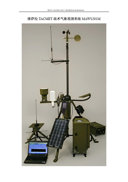
维萨拉TACMET战术气象观测系统MAWS201M维萨拉TACMET MAWS201M是一款便携式高性能自动气象站,适用于各种环境和任何天气情况。
产品特点●经济,部署快捷,便于携带的自动气象站●增强型配置可全面支持小型飞机跑道、空投场、测试区、无人机系统和未知机场●最紧凑的轻型系统,提供全面的航空支持●通过内置诊断和高质量传感器技术获得高可靠性和高精确度●坚固耐用的设计,适用于恶劣环境●增强冻雨检测●准确的二次风测量地点协助方法●预先配置的数字显示器,用于将数据分发到指挥中心紧凑轻巧的基本系统MAWS201M对风速/风向、空气温度、相对湿度(露点)、压力和降水量的数据进行采集、处理和输出报告。
该系统支持AC(主要)或者集成的太阳能板供电。
在不充电的情况下,备用电池可支持最少7天的供电。
增强系统的全面航空支持MAWS201M的增强型配置可全面支持航空应用。
附加的光学传感器组件增强了基本系统,用于云的高度和云覆盖范围、能见度、当前天气和闪电探测。
此外,可以向系统添加远程风站点和数字显示。
支持冻雨传感器的接入。
MAWS201M包括一个手持显示器,可用于设置站点特定参数,查看测量和计算参数,以及系统警报等功能。
强大的可移植性和易用性系统的机械结构即轻便又坚固。
所有电缆均配有快速拆卸连接器,让安装与拆卸快速方便。
轻便型携带箱结实耐用,在运输过程中能够起到良好的缓冲防护作用。
自动多功能报告根据情况,MAWS201M可以与先进的AviMet®软件交互,该软件可显示数字和图形,自动生成代码功能。
系统还可以根据用户定义的天气事件,自动发布METAR和SPECI报告。
报告中可以轻松设置备注信息。
该软件还可以进行归档和传输,以便对数据进行进一步处理。
高可靠性和高精度MAWS201M进行统计计算、数据质量控制和标准化格式输出。
内置的质量控制软件可根据用户设定的限制和连续测量之间的阶跃变化来验证传感器数据。
万一发生意外故障,MAWS201M可以进行自检,并且在现场可以对异常传感器进行快速更换。
SMC ZSE40A(F) ISE40A数字压力开关操作手册说明书

Digital Pressure SwitchOperation ManualZSE40A(F)/ISE40AThank you for purchasing the SMC ZSE40A(F)/ISE40A Series Digital Pressure Switch.Please read this manual carefully before operating the digital pressure switch and make sure you understand the digital pressure switch, its capabilities and limitations.Please keep this manual handy for future reference.To get information in detail for operating this product, refer to SMC website (URL ) or contact us.Indication light (Orange LED): Displays the switch operation condition.LCD display: Displays the current status of pressure, setting mode and error code.Four display modes can be selected to display always in red orgreen only, or changing from green to red, red to green according to the output status.button (UP): Selects the mode or increases the ON/OFF set value.Press this button to change to the peak display mode.button (DOWN): Selects the mode or decreases the ON/OFF set value.Press this button to change to the bottom display mode.button (SET): Press this button to change to either mode and to set a value.These safety instructions are intended to prevent hazardous situations and/or equipment damage.These instructions indicate the level of potential hazard with the labels of"Caution", " Warning" or "Danger". They are all important notes for safety and must be followed in addition to International standards (ISO/IEC), Japan Industrial Standards (JIS) and other safety regulations.OperatorInstallationMountingMount the optional bracket and panel mount adapter to the pressure switch.When the pressure switch is to be mounted in a place where water and dust splashes occur, insert a tube into the air-relieving port of the pressure switch.(Refer to "Tube attachment")Mounting with bracketFix the bracket to the pressure switch with the set screws M3x5L (2 pcs.) or M4x5L (2 pcs.) supplied.Apply a tightening torque of 0.5 to 0.7 Nm for the M3 set screws or 1.4 to 1.6 Nm for the M4 set screws .WiringConnection Make connection after turning the power e a separate route when connecting the wire ofthe Pressure switch.Malfunction stemming from noise may occur if the wire is installed in the same route as that of power or high-voltage cable.Be sure to ground terminal FG when using a commerically available switch-mode power supply.When the switch-mode power supply is connected to the Pressure switch,switching noise wil be superimposed and product specification can no longer be met. This can be prevented by inserting a noise filter, such as a line noise filter and ferrite core, between the switch-mode power supply and the Pressure switch, or by using a series power supply instead of the switch-mode power supply.Names of individual partsSet ON point and OFF point of the Pressure switch.Operation When the pressure exceeds a set value, the Pressure switch will be turned on.When the pressure falls below the set value by the amount of hysteresis or more, the Pressure switch will be turned off.The default setting of the output set value is the central value between the atmospheric pressure and the upper limit of the rated pressure range. If theoperation shown the right does not cause any problem, keep this operation setting.Switch ONP_1H_1Time [s]P r e s s u r e [P a ]<How to operate>button once in measurement mode.(2)[P_1] or [n_1] and set value are displayed in turn.Normal output Reversed outputbutton once to increase by one figure, and press it continuously to keep button once to decrease by one button to finish the setting of OUT1.[ Window comparator mode ]The Pressure switch turns on within a set pressure range (from P1L to P1H)during window comparator mode. Set P1L (switch lower limit) and P1H (switch At the time of shipment, the following settings are provided.If the setting is acceptable, keep it for use.To change setting, refer to SMC website (URL ) to get information in detail or contact us.[F 0] Unit conversion functionSame setting as [F 1] OUT1.At the output mode, Error detection mode can be selected.Display color is linked to the setting of OUT1, and can not be selected.Other parameter settingMeasurement modeThe measurement mode is the condition where the pressure is detected and indicated, and the switch function is operating.This is the basic mode, and other modes should be selected for setting change and other function setting changes.Function selection modeMeasurement modePeak/Bottom hold value indication Zero clear Key lockTo set each function the above in detail, refer to SMC website (URL ) to get information in detail or contact us.MaintenanceHow to reset the product after power cut or forcible de-energizing The setting of the product will be retained as it was before a power cut or de-energizing.The output condition is also basically recovered to that before a power cut or de-energizing, but may change depending on the operating environment.Therefore, check the safety of the whole facility before operating the product. If the facility is using accurate control, wait until the pressure switch has warmed up.(About 10 to 15 minutes)∗:Some functions are not available depending on part number. All functions are displayed with[F ] and followed with function description. If a function is not available for specified type, the function is displayed as [---].TroubleshootingError indication functionThis function is to display error location and content when a problem or an error occurs.SpecificationRefer to the product catalogue or SMC website (URL ) to get information about product specifications in detail.Outline with Dimensions (in mm)Refer to the product catalogue or SMC website (URL ) to get information about outline dimensions in detail.Akihabara UDX 15F, 4-14-1, Sotokanda, Chiyoda-ku, Tokyo 101-0021, JAPAN Phone: +81 3-5207-8249 Fax: +81 3-5298-5362URL Note: Specifications are subject to change without prior notice and any obligation on the part of the manufacturer.© 2009 SMC Corporation All Rights Reserved•Bracket A or D(Model: ZS-24-A/ZS-24-D)•Bracket B (Model: ZS-24-B)[01/N01 type][W1/WF1 type]button for 2[F 0]. Select to display the function setting to be changed, [F ].button for 2selection mode to return tomeasurement mode.。
精密测试仪器-MA 2012 单元型手动测试台说明书
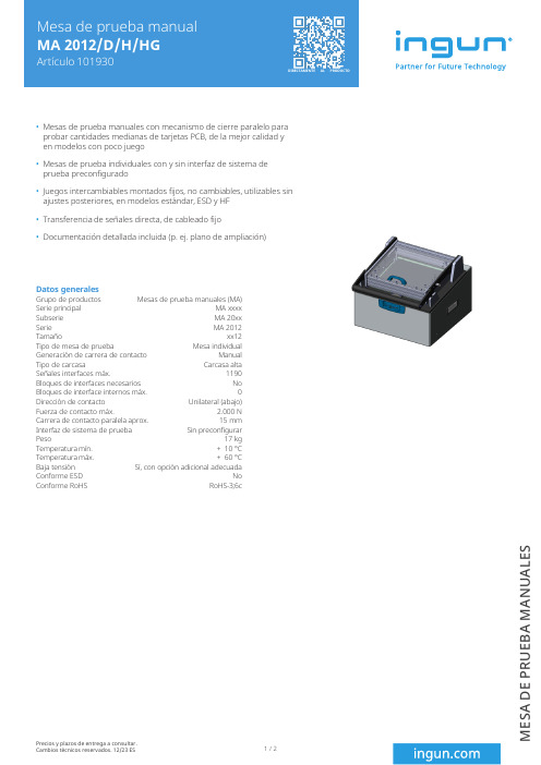
Mesas de prueba manuales con mecanismo de cierre paralelo para probar cantidades medianas de tarjetas PCB, de la mejor calidad y en modelos con poco juegoMesas de prueba individuales con y sin interfaz de sistema de prueba preconfiguradoJuegos intercambiables montados fijos, no cambiables, utilizables sin ajustes posteriores, en modelos estándar, ESD y HF Transferencia de señales directa, de cableado fijoDocumentación detallada incluida (p. ej. plano de ampliación)Grupo de productos Datos generalesMesas de prueba manuales (MA)Serie principal MA xxxx Subserie MA 20xx Serie MA 2012Tamaño xx12Tipo de mesa de prueba Mesa individual Generación de carrera de contacto Manual Tipo de carcasa Carcasa alta Señales interfaces máx.1190Bloques de interfaces necesarios No Bloques de interface internos máx.0Dirección de contacto Unilateral (abajo)Fuerza de contacto máx. 2.000 N Carrera de contacto paralela aprox.15 mm Interfaz de sistema de prueba Sin preconfigurar Peso 17 kg Temperatura mín.+ 10 °C Temperatura máx.+ 60 °C Baja tensión Sí, con opción adicional adecuada Conforme ESD No Conforme RoHS RoHS-3;6cPrecios y plazos de entrega a consultar.Cambios técnicos reservados. 12/23 ES1 / 2M E S A D E P R U E B A M A N U A L E SLongitud émbolo de pisador Altura de montaje libre sobre la placa de circuitos impresos 58mm Force of gas pressure springs 300 N (100 N a la izquierda) / 200N der.)Contacto adicional superior (ZSK)Sí, con opción adicional adecuada Datos técnicos60 mm Altura de montaje GKS superior 16 mm Altura de montaje GKS inferior 10,5 mm Altura de montaje GKS 2 fases inferior 16 mm Altura de montaje libre sobre la placa de circuitos impresos 58mm Force of gas pressure springs 300 N (100 N a la izquierda) / 200N der.)Ángulo de apertura pisador 75 °Modelo estándar SíSuperficie útil estándar (AnxP)285 x 240 mm Modelo ESD No Modelo radiofrecuencia No Modelo aguja rígida No Modelo 2 fases Sí, con opción adicional adecuada Superficie útil 2 fases (AnxP)285 x 240 mm Contacto adicional superior (ZSK)Sí, con opción adicional adecuada Dimensiones exteriores abierto (AnxPxAl)492 x 461 x 688 mm Dimensiones exteriores cerrado (AnxPxAl)492 x 515 x 370 mmINGUN Prüfmittelbau GmbHMax-Stromeyer-Straße 16278467, Constance, Germany Phone +49 7531 8105-0Customer hotline +49 7531 8105-888Fax +49 7531 8105-65**************Precios y plazos de entrega a consultar.Cambios técnicos reservados. 12/23 ESMás información sobre el tema Mesas de prueba manuales (MA)2 / 2M E S A D E P R U E B A M A N U A L E S。
VBAT-OM-S008操作手册,VBAT-M46A空气坡头,SMC品牌
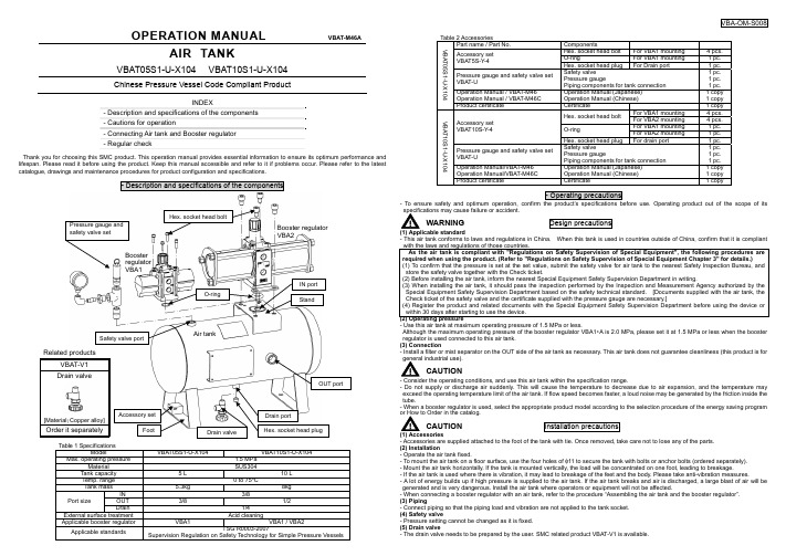
VBA-OM-S008OPERATION MANUALVBAT-M46AAIR TANKVBAT05S1-U-X104 VBAT10S1-U-X104Chinese Pressure Vessel Code Compliant ProductINDEX- Description and specifications of the components - Cautions for operation- Connecting Air tank and Booster regulator - Regular checkThank you for choosing this SMC product. This operation manual provides essential information to ensure its optimum performance and lifespan. Please read it before using the product. Keep this manual accessible and refer to it if problems occur. Please refer to the latest catalogue, drawings and maintenance procedures for product configuration and specifications.- Description and specifications of the componentsTable 1 SpecificationsModel VBAT05S1-U-X104VBAT10S1-U-X104Max. operating pressure1.5 MPaMaterial SUS304 Tank capacity 5 L 10 LTemp. range 0 to 75oC Tank mass 5.3kg 8kgIN 3/8OUT 3/8 1/2Port size Drain 1/4External surface treatment Acid cleaning Applicable booster regulator VBA1 VBA1 / VBA2Applicable standardsTSG R0003-2007Supervision Regulation on Safety Technology for Simple Pressure VesselsTable 2 AccessoriesPart name / Part No. Components Hex. socket head bolt For VBA1 mounting 4 pcs. O-ring For VBA1 mounting 1 pc. Accessory set VBAT5S-Y-4Hex. socket head plug For Drain port 1 pc.Pressure gauge and safety valve set VBAT-USafety valvePressure gaugePiping components for tank connection1 pc. 1 pc. 1 pc. Operation Manual / VBAT-M46 Operation Manual / VBAT-M46C Operation Manual (Japanese) Operation Manual (Chinese) 1 copy 1 copy VBAT05S1-U-X104 Product certificate Certificate 1 copyFor VBA1 mounting 4 pcs.Hex. socket head boltFor VBA2 mounting 4 pcs. For VBA1 mounting 1 pc.O-ringFor VBA2 mounting 1 pc.Accessory set VBAT10S-Y-4Hex. socket head plug For drain port 1 pc.Pressure gauge and safety valve set VBAT-USafety valvePressure gaugePiping components for tank connection1 pc. 1 pc. 1 pc. Operation Manual/VBAT-M46 Operation Manual/VBAT-M46C Operation Manual (Japanese) Operation Manual (Chinese) 1 copy 1 copyVBAT10S1-U-X104Product certificateCertificate 1 copy- Operating precautions- To ensure safety and optimum operation, confirm the product’s specifications before use. Operating product out of the scope of its specifications may cause failure or accident.△! WARNING Design precautionsHex. socket head bolt(1) Applicable standard- This air tank conforms to laws and regulations in China. When this tank is used in countries outside of China, confirm that it is compliant with the laws and regulations of those countries.As the air tank is compliant with "Regulations on Safety Supervision of Special Equipment", the following procedures are required when using the product. (Refer to "Regulations on Safety Supervision of Special Equipment Chapter 3" for details.) (1) To confirm that the pressure is set at the set value, submit the safety valve for air tank to the nearest Safety Inspection Bureau, and store the safety valve together with the Check ticket.(2) Before installing the air tank, inform the nearest Special Equipment Safety Supervision Department in writing.(3) When installing the air tank, it should pass the inspection performed by the Inspection and Measurement Agency authorized by the Special Equipment Safety Supervision Department based on the safety technical standard. [Documents supplied with the air tank, the Check ticket of the safety valve and the certificate supplied with the pressure gauge are necessary.](4) Register the product and related documents with the Special Equipment Safety Supervision Department before using the device or within 30 days after starting to use the device. (2) Operating pressure- Use this air tank at maximum operating pressure of 1.5 MPa or less.Although the maximum operating pressure of the booster regulator VBA1∗A is 2.0 MPa, please set it at 1.5 MPa or less when the booster regulator is used connected to this air tank. (3) Connection- Install a filter or mist separator on the OUT side of the air tank as necessary. This air tank does not guarantee cleanliness (this product is for general industrial use).△! CAUTION- Consider the operating conditions, and use this air tank within the specification range.- Do not supply or discharge air suddenly. This will cause the temperature to decrease due to air expansion, and the temperature may exceed the operating temperature limit of the air tank. If flow speed becomes faster, a loud noise may be generated by the friction inside the tube.- When a booster regulator is used, select the appropriate product model according to the selection procedure of the energy saving program or How to Order in the catalog.△! CAUTION Installation precautions(1) Accessories- Accessories are supplied attached to the foot of the tank with tie. Once removed, take care not to lose any of the parts. (2) Installation- Operate the air tank fixed.- To mount the air tank on a floor surface, use the four holes of φ11 to secure the tank with bolts or anchor bolts (ordered separately). - Mount the air tank horizontally. If the tank is mounted vertically, the load will be concentrated on one foot, leading to breakage.- If the air tank is used where there is vibration, it may lead to breakage of the feet and the body. Please take anti-vibration measures.- A lot of energy builds up if high pressure is supplied to the air tank. If the air tank breaks and air is discharged, a large blast of air will be generated and is very dangerous. Install the air tank where operators or equipment will not be affected.- When connecting a booster regulator with an air tank, refer to the procedure “Assembling the air tank and the booster regulator”. (3) Piping- Connect piping so that the piping load and vibration are not applied to the tank socket. (4) Safety valve- Pressure setting cannot be changed as it is fixed. (5) Drain valve- The drain valve needs to be prepared by the user. SMC related product VBAT-V1 is available.O-ringAir tankBooster regulator VBA2Safety valve portRelated productsVBAT-V1 Drain valve[Material :Copper alloy]Order it separatelyIN port (I)Safety valve portRc3/8OUT port(J) Drain port Rc1/4IN port Rc3/84×φ11 - Connecting Air Tank and Booster Regulator(1) Accessory check: Check the items and the quantity of parts in the package shown in Table 2.(Accessories are attached to the foot of the air tank.)(2) Prepare tools: Prepare a hexagon wrench key. The hexagon wrench keyfor VBA1 is with nominal size 4 and 6, for VBA2 with nominal size 8, and for the drain port with nominal size 6.: Tighten the optional safety valve and drainvalve with a monkey spanner.(3) Change of the booster regulator OUT port plugof the booster regulator. (Remove any sealing agent left on the thread.) booster regulator by applying the seal tape. VBA1: Tightening torque of 12 to 14 Nm (R1/4) VBA2: Tightening torque of 22 to 24 Nm (R3/8) (4) O-ring: Mount the O-ring in the groove on the joint of the tank at the back of the booster regulator.(5) Mounting direction: When mounting the booster regulator VBA2 to the air tank VBAT10S1-∗, the direction of IN of the booster regulator and OUT of the air tank can be changed to suit the application. Align the direction of the booster regulator IN port and the air tank OUT port when mounting the booster regulator VBA1.(6) Installation: Tighten diagonally with the hexagon socket head bolts included in the package.VBA1: Tightening torque: 3 Nm (M5) VBA2: Tightening torque: 24 Nm (M10)Assembly dimensionsAir tankBoosterregulator φ A B C D E F G H I J K L MVBAT05S1VBA10A VBA11A 150337********* 160 100 200 Rc3/825760VBA10AVBA11A 391328Rc 1/420VBAT10S1VBA20A VBA22A 180460454417367170 180 120 312 Rc 3/8Rc1/2 39278130- Maintenance△! WARNING(1) Regular check- The user of the air tank shall keep a record of maintenance by making a special equipment safety technical document. - The use of a pressure vessel could lead to an unexpected accident due to external damage or internal corrosion caused by drainage. Therefore, make sure to check periodically for external damage, or the extent of internal corrosion through the port hole. An ultrasonic thickness indicator may also be used to check for any reduction in material thickness.(2) Drain discharge- If the product is used with a large amount of drainage, the drainage could flow out, leading to equipment malfunction or corrosion inside the tank. Perform drain flushing regularly. Phone: +81 3 5207 8249 Fax: +81 3 5298 5362Specifications are subject to change without prior notice and any obligation the part of the manufacturer. 2008 SMC Corporation All Rights ReservedURL Akihabara UDX 15F,4-14-1, Sotokanda, Chiyoda-ku, Tokyo 101-0021, JAPANMounting baseVBAT05S1-∗ VBAT10S1-∗VBA1 VBA2OUT ->。
机械设备安装维护手册范本
酒泉钢铁(集团)有限责任公司200万吨热轧薄板项目铁钢项目部炼钢常规板坯连铸机工程机械设备安装维护手册R605C0502二OO四年九月酒泉钢铁(集团)有限责任公司200万吨热轧薄板项目铁钢项目部炼钢常规板坯连铸机工程机械设备安装维护手册R605C0502审核:胡波编制:陆华二OO四年九月目录1.前言 (3)2.机械设备制造及施工安装验收标准 (4)3.连铸机基准线和基准点 (5)4.机械设备说明 (6)4.1钢结构 (6)4.2钢包回转台 (8)4.3.钢包加盖机构 (12)4.4 中间罐及塞棒启闭机构 (13)4.5中间罐车组 (13)4.6结晶器 (17)4.7振动装置 (20)4.8弯曲段 (22)4.9扇形段1~6 (23)4.10扇形段7 (28)4.11扇形段8 (30)4.12扇形段9~13 (33)4.13基础框架 (35)4.14扇形段驱动装置 (38)4.15扇形段更换导轨 (40)4.16脱引锭装置 (41)4.17切割前辊道 (43)4.18切割下辊道 (44)4.19 自动火焰切割机 (46)4.20切头筐 (47)4.21切后及引锭存放辊道 (47)4.22下线辊道 (48)4.23引锭杆及引锭杆存放装置 (49)4.24中间罐烘烤及干燥装置................................... 错误!未定义书签。
4.25油气润滑系统 (52)4.26液压系统 (52)4.27结晶器维修对弧台 (53)4.28弯曲段对弧台 (55)4.29扇形段内弧和外弧对弧台 (55)4.30喷嘴试验台 (55)4.31振动单元试验台 (55)5. 连铸机弧形段设备的定位 (55)6. 连铸机整机的试运行 (56)7. 连铸机的维护要点 (56)1.前言1.1 本说明书是酒泉钢铁(集团)有限责任公司200万吨热轧薄板项目铁钢项目部炼钢常规板坯连铸机工程设计文件不可分割的一部分,与设计图纸具有同等效力。
重庆川仪气动执行器样本

产品技术规格P E C I F I C A T I O N S®调节阀配件AccessoriesHA 多弹簧薄膜执行机构Pneumatic Multi-spring Diaphragm ActuatorsHA多弹簧薄膜执行机构是一种采用多弹簧结构,体积小、重量轻、性能高、输出力大的直行程气动薄膜执行机构。
HA多弹簧薄膜执行机构,它把气动调节仪表的输出压力转换成推杆位移的变化。
因此,只要它与调节阀的阀体部分相应连接就可把阀芯移到与输入信号相对应的位置。
该执行机构与本公司的定位器配合使用可实现高精度的位置控制。
This Series provides high performance, high power diaphragm actuators of multi-spring type that are compact and light.It accepts the pneumatic output of a control instrument and converts the pneumatic force into a mechanical force with diaphragm that can make the stem moving. Thereby, it can drive the plug to a set position after installing on the valve body.Combination with the positioner provides high accuracy position control..重庆川仪调节阀有限公司Chongqing Chuanyi Control Valve Co.,Ltd.表1 HA执行机构行程范围及输出力重庆川仪调节阀有限公司Chongqing Chuanyi Control Valve Co., Ltd.表2 手轮机构配置表3 外形尺寸及重量注:尺寸L是供气压力为零时的尺寸,括号内数字是反作用执行机构的尺寸。
麦克西莫特手动阀气动执行器 MT R3 0713说明书
Air Pressure Required to Open Valve At: System Pressure (ksi)
1-4 6
8
10
65 65 65 75 0.19 0.19 0.19 0.25
0.25 35 35 35 40 0.19 0.19 0.19 0.25
0.25 65 65 75 85 0.19 0.19 0.25 0.31
5.67”
3.94”
1/8” NPT
(2) 9/32” Dia. Mounting Holes Centered 1 1/8” apart
Valve Series
21V4
21V6, 15V4,
**
21V9, 15V6, 15V8,
**
21V12
21V16
Air Actuator
Type
Ordering Suffix
All general terms and conditions of sale, including limitations of our liability, apply to all products and services sold. MT R3 0713
4%#(./,/')%3
Air Valve Actuators
Medium Duty Actuator
Heavy Duty Actuator
3.94”
1/8” NPT
(2) 9/32” Dia. Mounting Holes Centered 1 1/8” apart
(2) 9/32” Dia. Mounting Holes Centered 1 1/8” apart
SMC

Ÿ DPI 通信 Ÿ 液晶显示屏 Ÿ 键盘编程 Ÿ 四个可编程辅助触点
目录
特性 ............................................... 本页 目录号说明............................ 8 产品选型................................... 9 选件 ............................................... 19 附件 ............................................... 20 技术参数................................... 22 近似尺寸................................... 27
100%
ۉუӥݴຕ
100%
ཌഔۯ
ۉუӥݴຕ
؛๔ ገਈ
ഔۯ
ሏႜ
้क़ (௱)
限流启动
该方法提供限流启动,用于必须限制最大启动电流的场合。启动电流 的大小可由用户调整。电流限制作用时间也可由用户调整。
600%
้क़ (௱)
线性加速 在这种加速模式下,闭环反馈系统使电机以恒定的速率保持加速。 所需的反馈信号由与电机相连的直流转速计提供 (转速计由用户自备, 0…5 V DC,4.5 V DC = 100% 转速)。这种模式支持突跳启动。
欠载保护 利用 SMC Flex 控制器的欠载保护,可在检测到电流下降时暂停电机 操作。 SMC Flex 控制器提供可调的欠载脱扣设置,设置范围为所设定的电机 满负载电流额定值的 0…99%,而脱扣延迟时间可在 0…99 秒之间进行 调节。
microaire 7000 系列大功率气动器械系统 说明书
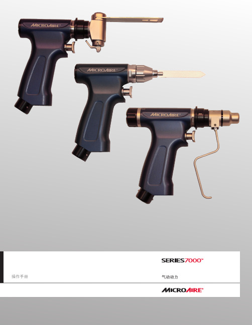
操作手册气动动力目录7000系列大功率气动器械系统简介和一般警告 . . . . . . . . . . . . . . . . . . . . . . . . . . . . . . . . . . . .3标志 . . . . . . . . . . . . . . . . . . . . . . . . . . . . . . . . . . . . . . . . .4标准和环境参数 . . . . . . . . . . . . . . . . . . . . . . . . . . . . . . . . . . . .4 REF7105-XXX 钻铰复合刀具机头............................5-8 REF7205-XXX 摆锯.................................8-11 REF7405-XXX 往复锯................................12-15传动联轴器 . . . . . . . . . . . . . . . . . . . . . . . . . . . . . . . . . . . .16-24清洁和灭菌说明 . . . . . . . . . . . . . . . . . . . . . . . . . . . . . . . . . .25-28故障排除 . . . . . . . . . . . . . . . . . . . . . . . . . . . . . . . . . . . . . . 29保修、服务与维修 . . . . . . . . . . . . . . . . . . . . . . . . . . . . . . . . .30-31简介本手册旨在描述 MicroAire7000 系列大功率气动系统与各型号机头正常工作的过程:REF7105-XXX、REF7205-XXX 和 REF7405-XXX。
川仪M系列电动执行机构样本
33
93.5
114
150
160
210
280
330
400
142
151.5
175
198
81
83
94
113
4-M16深25 4-M20深30
8-M16深22
8-M20深 32
—
4
4
4
—
130
200
230
140
165
254
298
204
244
310
350
35
35
54
54
75
80
105
105
104
130
133
158
葵花接线盒
插拔式接线方式让更换执行机构变得更加方便 快捷,只需把葵花盘插入接线盒即可,免去了 二次接线
绝对编码器
阀输出轴带动绝对编码器转动,形成的编码信 号送入主控芯片计算出当前阀位值,用作阀位 显示信号。由于绝对编码器获取的是阀位的绝 对信息,掉电和干扰均不会对其造成影响,得 到的阀位永远是正确的。
520
630
135
223
270
338
448
580
52.5
36
40
36
36
25
68.5
93.5
114
150
160
250
15
25
23
24
30
30
263.5
332
369.5
F14:46(618) F16:466
668
666
477
546
583
678(832)F16:738
- 1、下载文档前请自行甄别文档内容的完整性,平台不提供额外的编辑、内容补充、找答案等附加服务。
- 2、"仅部分预览"的文档,不可在线预览部分如存在完整性等问题,可反馈申请退款(可完整预览的文档不适用该条件!)。
- 3、如文档侵犯您的权益,请联系客服反馈,我们会尽快为您处理(人工客服工作时间:9:00-18:30)。
型号表示方法
※导线长度记号 0.5m……………无记号(例) M9NW
1m…………… M (例) M9NWM
3m…………… L (例) M9NWL
5m…………… Z (例) M9NWZ
※○号的无触点磁性开关按订货规格生产。
※磁性开关同包出厂(未组装)。
※※可安装耐水性强的磁性开关,但不表示摆动气缸耐水性强。
无触点磁性开关带导线前置插头型详见
P.843、844。
摆台/齿轮齿条式
MSQ系列
尺寸: 10, 20, 30, 50, 70, 100, 200
307
CRB2
-Z
CRBU2
CRB1
MSU
D-;
规格
注1) 缓冲器的最大允许推力决定执行元件的最高使用压力。
注2) 带内部缓冲器的摆动角度设定时,若小于下表的值,按缓冲器的有效行程,活塞的有效行程变小,
允许动能与摆动时间调整范围
注) 不含磁性开关质量的值。
质量
(g)
JIS 图形符号
基本型/MSQB
高精度型/MSQA
液压缓冲器的寿命,根据使用条件,与摆台本体不同。
更换标准请参见单独注意事项栏。
注1) 超过允许值的动能动作的场合,产品内部有可能发生会破损,不能使用,故设计、运转时,要特别
注意不要超过动能的允许值。
注2) 内部缓冲器的摆动时间设定比表中值长的场合,液压缓冲器的动能吸收能力明显下降,请注意。
MSQ 系列
端面通口
侧面通口
308
90°摆动
90°摆动90°摆动摆动角度范围的设定例
·通过对调整螺钉A 、B 的调整,如下图,可设定不同的摆动范围。
(图中表示了定位销孔的摆动范围)
·带内部液压缓冲器的场合,同样也可设定摆动角度。
摆动方向及摆动角度
·从A 口加压,摆台顺时针回转,从B 口加压,摆台则逆时针回转。
·通过对调整螺钉的调整,在下图范围内设定回转端,可得到任意的摆动角度。
·带内部液压缓冲器的场合,同样也可设定摆动角度。
摆台/齿轮齿条式
MSQ 系列
309
CRB2-Z
CRBU2CRB1MSU
D-;
洁净系列
从摆台侧面的真空口进行真空吸引,使产品内部的发尘不会在洁净室内飞散。
外形尺寸图
洁净系列的回转中心无中空孔。
型号表示方法规格
注1)详细内容参见样本「空气压洁净系列」。
基本型
11-MSQB □A 11-MSQB □
高精度型
11-MSQA □A 11-MSQA □
上表以外的尺寸与基本型相同。
上表以外的尺寸与高精度型相同。
MSQ 系列
除以上规格外,其他规格与11-MSQA 高精度型,11-MSQB 基本型相同。
310
结构图
MSQA □□(高精度型)
MSQ □□ R (带内部缓冲器)
润滑脂包型号:GR-S-010(10g)
※不能对应单独零件的出厂。
311
摆台/齿轮齿条式
MSQ 系列
CRB2-Z
CRBU2CRB1MSU
D-;
外形尺寸图/尺寸10, 20, 30, 50基本型/MSQB □A
带内部液压缓冲器MSQA □R MSQB □R 高精度型
MSQA □A /带调整螺钉
MSQA □R /带内部液压缓冲器
※Rc1/8以外,也可选择G1/8、NPT1/8。
MSQ 系列
312
外形尺寸图/尺寸70, 100, 200基本型/MSQB □A
带液压缓冲器
MSQB □R
※Rc1/8以外,也可选择G1/8、NPT1/8。
摆台/齿轮齿条式
MSQ 系列
313
CRB2-Z
CRBU2CRB1MSU
D-;。