气动执行器说明
ACTUATECH气动执行器说明书

INSTRUCTION MANUALPart turn pneumatic actuatorwith Manual Override-Complete aluminium protection versionGDV60 - GDV3840 GSV30 – GSV19201)GENERAL FEATURES………………………………………………………………………………………………..pg.32)DATASHEET……………………………………………………………………………………………..pg.43)FUNCTIONAL DESCRIPTION……………………………………………..………….…………………….……………pg.54)DANGERS……….………………………………………………………………………………………..pg.75)PART DESCRIPTION……………..………………………………………………………….………………….pg.86)TRUOBLESHOOTING ………………………………………..…………………...…………………….pg.97)DISPOSAL…….………………...………………………………………………………..…………….....pg.9Environmentally friendly handling of the product.1)GENERAL FEATURES ••••••••••••••••••••••••••••••••••••••••••••••••••••••••••••••••••••••••••••••••••••••••••••••••••Actuatech manufacture a manual handwheel override for a wide range of part turn pneumatic actuators.The actuators with manual override are available on Double Acting “GDV” and Spring Return “GSV” versions.- The principle of the manual handwheel override application is to provide the possibility to open and close the valve connected to the actuator when this operation can’t be done with remote control.- Actuatech manual override actuator is itself equipped with an handwheel for manual operations and it doesn’t need any added declutchable gear box. This solution guarantees a compact size and a more light system on the valve.- When the actuator is manual operated it can be locked in Open/Closed position.- Actuator versions for low temperature and high temperature applications allow to operate respectively until temperatures of -50°C and +150°C, thanks to proper kind of lubrication and material for the gaskets.The maintenance should be done by Actuatech trained personnel only.This instruction manual contains important information regarding the Actuatech manual override actuator operation, installation, maintenance and storage.Please read carefully before installation and keep it in a safe place for further reference.Modification reserved. Rev.date 04/2018. No guarantee for accuracy. Older data sheets are invalid 2)DATASHEET•••••••••••••••••••••••••••••••••••••••••••••••••••••••••••••••••••••••••••••••••••••••••••••••••• DOUBLEACTINGNOMINALTORQUE (Nm)ISOFLANGESQUAREØHANDWEELRim pull forces ( N )To obtain thenominal torqueWeight( Kg )Teorical n° of turnsto close / openstarting from theneutral positionA B C DGDV60 60 F05-F07 14 180 19.3 2.8 11 - 99 263.3 137.6 GDV106 106 F05-F07 17 180 27.8 4 13 - 118.5 279.3 154.8 GDV120 120 F05-F07 17 180 33.8 4.5 14 - 122.1 288.4 163.9 GDV180 180 F07-F10 22 220 44.1 6 16 - 144.9 338.1 183.5 GDV240 240 F07-F10 22 220 54.5 8 18 - 156.8 353.7 199.1 GDV360 360 F07-F10 22 300 67.5 10.2 15 - 169.6 398 220.8 GDV480 480 F10-F12 27 300 83.3 13.2 16 - 193.8 440.6 236.4 GDV720 720 F10-F12 27 350 108.8 17.8 19 - 216.6 503.5 282.3GDV960 960 F10-F12 /F1436 350 128.6 23.8 20 - 239.7 518.3 297.1 GDV1440 1440 F12 / F14 36 400 133.5 33.6 25 - 283.5 636.4 365.6GDV1920 1920 F12-F16 /F1446 400 162.5 43 26 - 300.4 653.7 382.9 GDV3840 3840 F16 46 575 243.5 75 30 - 353.3 890.2 537.5SIMPLEACTINGNOMINALTORQUE (Nm)ISOFLANGESQUAREØHANDWEELRim pull forces ( N )To obtain thenominal torqueWeight( Kg )Teorical n° of turnsto close / openstarting from theneutral positionA B C DGSV30 30 F05-F07 14 180 19.3 3.2 11 129.4 - 263.3 137.6 GSV053 53 F05-F07 17 180 27.8 4.5 13 152.1 - 279.3 154.8 GSV060 60 F05-F07 17 180 33.8 4.5 14 169.3 - 288.4 163.9 GSV090 90 F07-F10 22 220 44.1 6.8 16 196.8 - 338.1 183.5 GSV120 120 F07-F10 22 220 54.5 9 18 204.8 - 353.7 199.1 GSV180 180 F07-F10 22 300 67.5 11.7 15 237 - 398 220.8 GSV240 240 F10-F12 27 300 83.3 15.2 16 260.2 - 440.6 236.4 GSV360 360 F10-F12 27 350 108.8 19.5 19 306.6 - 503.5 282.3GSV480 480 F10-F12 /F1436 350 128.6 28.1 20 324.1 - 518.3 297.1GSV720 720 F12 / F14 36 400 133.5 38.8 25 399 - 636.4 365.6GSV960 960 F12-F16 /F1446 400 162.5 50.6 26 414 - 653.7 382.9GSV1920 1920 F16 46 575 243.5 91 30 509 - 890.2 537.5 All the dimensions are in mm, for missing data see standard catalogue .Modification reserved. Rev.date 04/2018. No guarantee for accuracy. Older data sheets are invalid3) FUNCTIONAL DESCRIPTION •••••••••••••••••••••••••••••••••••••••••••••••••••••••••••••••••••••••••••••••••••••••••••••••••• NB: PRIOR TO MANUAL OVERRIDE OPERATE, ENSURE THAT THE ACTUATOR IS FREE FROM PRESSURE.1.Remove the cap to ensure there is no pressure in the actuator2.Engage the manual override and operate as required3.Disconnect the manual override (neutral position)*for standard actuators.TO CLOSE THE VALVETo close the valve turn the wheel in clockwise direction*.TO OPEN THE VALVETo open the valve turn the wheel in counterclockwise direction.* NB: Before commissioning to ensure proper disengagement, perform an ON-OFF maneuver of the actuatorModification reserved. Rev.date 04/2018. No guarantee for accuracy. Older data sheets are invalidNB: WHEN THE ACTUATOR HAS BEEN MANUALLY OPERATED, RETURN TO THE NEUTRAL POSITION PRIOR TO START NORMAL OPERATIONS.NEUTRAL POSITIONWith the screw in neutral position the piston can move freely and the actuator can be driven pneumatically. MANUAL OPERATION GDV : The handwheel turned counter clockwise, pushes the screw and piston inwards. The valve opens. GSV : The handwheel turned clockwise pushes the screw and piston inwards. The valve closes.MANUAL OPERATIONGDV : When the handwheel is turned clockwise, the screwand piston are drawn outwards. The valve closes. GSV : When the handwheel is turned counter clockwise, the screw and the piston are drawn outwards. The valve opens.Modification reserved. Rev.date 04/2018. No guarantee for accuracy. Older data sheets are invalid4)WARNINGS •••••••••••••••••••••••••••••••••••••••••••••••••••••••••••••••••••••••••••••••••••••••••••••••••• a) Don’t disassemble, compressed spring inside.b) Don’t use levers or bars.c) Don’t use the handwheel to lift the actuator.NB:Manual override is not recommended for safety related applications (SIL) as bypass of a security function. In this application, to prevent an unauthorized use, the manual override is provided with a locking device.Modification reserved. Rev.date 04/2018. No guarantee for accuracy. Older data sheets are invalid5)PART DESCRIPTION ••••••••••••••••••••••••••••••••••••••••••••••••••••••••••••••••••••••••••••••••••••••••••••••••••NB: In the case of actuator low or high temperature the pistons and the material of the O ring are different from the standard actuator.Modification reserved. Rev.date 04/2018. No guarantee for accuracy. Older data sheets are invalid6)TROUBLESHOOTING •••••••••••••••••••••••••••••••••••••••••••••••••••••••••••••••••••••••••••••••••••••••••••••••••• POTENTIAL EFFECT OFFAILUREPOTENTIAL CAUSE OF FAILURE SOLUTION Difficult manual operationsBlocked valve Repair or replace the valvePresence of particles inside the actuator due toan incorrect filtration of the airVerify the condition of the supply airand contact ActuatechThe actuator is pressurized Remove supply air7)DISPOSAL •••••••••••••••••••••••••••••••••••••••••••••••••••••••••••••••••••••••••••••••••••••••••••••••••• Our products are designed so that when they are at the end of their life cycle they can be completely disassembled, separating the different materials for the proper disposal and/or recovery. All materials have been selected in order to ensure minimal environmental impact, health and safety of personnel during their installation and maintenance, provided that, during use, they are not contaminated by hazardous substances.The personnel in charge of the product disposal/recovery, must be qualified and equipped with appropriate personal protective equipment (PPE), according to the product size and the type of service for which the device was intended. The management of waste generated during the installation, maintenance or due to the product disposal, is governed by the rules in force in the country where the product is installed, in any case, the following are general guidelines:- The metal components (aluminum/steel) can be restored as raw material;- Seals/sealing elements as contaminated by fluids from other materials and lubrication,must be disposed of.- The packaging materials that come with the product, should be transferred to the differentiated collection systemavailable in the country.。
气动执行器结构及原理
气动执行器结构及原理 The final edition was revised on December 14th, 2020.气缸结构与原理学习气动执行机构气动执行机构俗称又称气动执行器(英文:Pneumatic actuator )按其能源形式分为气动,电动和液动三大类,它们各有特点,适用于不同的场合。
气动执行器是执行器中的一种类别。
气动执行器还可以分为单作用和双作用两种类型:执行器的开关动作都通过气源来驱动执行,叫做DOUBLE ACTING (双作用)。
SPRING RETURN (单作用)的开关动作只有开动作是气源驱动,而关动作是弹簧复位。
气动执行机构简介气动执行器的执行机构和调节机构是统一的整体,其执行机构有薄膜式、活塞式、拨叉式和齿轮齿条式。
活塞式行程长,适用于要求有较大推力的场合;而薄膜式行程较小,只能直接带动阀杆。
拨叉式气动执行器具有扭矩大、空间小、扭矩曲线更符合阀门的扭矩曲线等特点,但是不很美观;常用在大扭矩的阀门上。
齿轮齿条式气动执行机构有结构简单,动作平稳可靠,并且安全防爆等优点,在发电厂、化工,炼油等对安全要求较高的生产过程中有广泛的应用。
齿轮齿条式:齿轮齿条:活塞式:气动执行机构的缺点控制精度较低,双作用的气动执行器,断气源后不能回到预设位置。
单作用的气动执行器,断气源后可以依靠弹簧回到预设位置工作原理说明班当压缩空气从A管咀进入时,气体推动双活塞向两端(缸盖端)直线运动,活塞上的齿条带动旋转轴上的齿轮逆时针方向转动90度,阀门即被打开。
此时气动执行阀两端的气体随B管咀排出。
反之,当压缩空气从B官咀进入气动执行器的两端时,气体推动双塞向中间直线运动,活塞上的齿条带动旋转轴上的齿轮顺时针方向转动90度,阀门即被关闭。
此时气动执行器中间的气体随A管咀排出。
以上为标准型的传动原理。
根据用户需求,气动执行器可装置成与标准型相反的传动原理,即选准轴顺时针方向转动为开启阀门,逆时针方向转动为关闭阀门。
STI气动执行器使用说明书
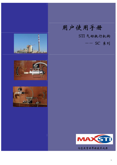
用户使用手册STI 气动执行机构 ―― SC 系列与您共享世界新技术成果目 录声明 (3)一﹑产品介绍 (4)1.1简述 (4)1.2功能特性 (4)1.3技术资料 (4)1.4系统原理 (4)二﹑安装说明 (6)2.1安装准备 (6)2.2气路和电路连接 (6)2.3控制柜和执行器现场安装图 (7)三﹑调试说明 (8)3.1 DE/3M-1气动执行机构 (8)3.2 SA/CL-1气动执行机构 (8)3.3 2030电子式位置变送器 (9)四﹑设备维护 (11)4.1搬运 (11)4.2储存 (11)4.3维护 (11)4.4垫圈的更换 (11)五﹑常见设备故障及处理 (13)六﹑附录 (15)声 明一.感谢您购买大连万讯电力仪表有限公司所代理的,意大利原装STI气动执行机构,以及本公司所生产的配套气动控制柜。
二.请在设备到现场后,应放置在干燥﹑清洁的地方,防止受潮淋雨,造成设备进水导致不能正常工作并且影响设备寿命。
在设备安装前认真阅读本说明书,并严格按照本说明书的要求去执行。
三.作为气动设备,本公司强烈要求您在使用前,对供气设备及气路进行检查,防止有粉尘杂质进入设备,造成设备的堵塞甚至损坏,另外由于本设备是精密自控设备,有的部件比较脆弱,请在安装调试时特别注意。
对于使用过程中,由于误操作引起的损失,我公司不承担任何经济责任。
产 品 介 绍1.1意大利STI 公司成立于1960年,是世界上著名的执行机构专业生产商,其产品广泛使用于电厂、石油化工、冶金、造纸、水泥等行业。
STI 产品为世界许多锅炉及特种阀门厂如:ABB、BTG、BRAY、LONZA、WHEELER 等所采用,成为其特种阀门和风门的OEM 供应商。
STI 产品系列SC/V 系列:适合于对阀门的控制SC 长行程系列:配以连杆可实现对风门挡板的控制 APL、CML、CMV 系列: 用于风门挡板和蝶阀的控制 辅助装置:定位器、位置变送器、气锁系统、加速单元 气体过滤干燥装置:用于气源的干燥过滤1.2SC 系列气动执行机构推力和行程较大,双耳环的设计使安装固定更容易,活塞杆通过U 型夹可直接同摆动燃烧器档板联接。
气动执行器的产品说明书

S E R I E S P L S O L E N O I D V A L V E SDirect acting solenoid valves Series PL2/2-way - Normally Open (NO)3/2-way - Normally Closed (NC) and Normally Open (NO) 3/2-way - Universal (UNI)Series PL solenoid valves are available in the normally closed, normally open and universal versions. They can be mounted on single sub-bases or manifolds.Please note that all Series PL solenoid valves are supplied with direct current (DC). To operate in alternating current (AC), it is necessary to use the connector with bridge rectifier Mod. 125-900.»Application sectors: - Industrial Automation - Life Science - Transportation »Mounting on a single base (M5 connections) or on manifold (M5 or fittings Ø3 and Ø4)GENERAL DATATECHNICAL FEATURES Function OperationPneumatic connections Orifice diameterFlow coefficient kv (l/min) Operating pressure Operating temperature MediaResponse time Manual override Installation2/2 NO - 3/2 NC - 3/2 NO - 3/2 UNI direct acting poppet type on subbase 0.8 ... 1.6 mm 0.30 ... 0.62 0 ÷ 3.5 ... 10 bar0 ÷ 50 °C (FKM) / -50 ÷ 50 °C (low temperature NBR on demand)filtered air class [5:4:4] according to ISO 8573-1:2010 (max oil viscosity 32 cSt), inert gas ON <10 ms - OFF <15 msmono/bistable - PBT 3/2 versions onlyin any positionMATERIALS IN CONTACT WITH THE MEDIUM Body SealsInternal parts brass - PBT - PPSFKM - NBR - EPDM (on demand) brass - stainless steelELECTRICAL FEATURES VoltageVoltage tolerance Power consumption Duty cycleElectrical connection Protection class6 ... 110 V DC - other voltages on demand ±10% 1.2 ... 3 W ED 100%industry standard connector (9.4 mm) IP65 with connectorSpecial versions available on demandS E R I E S P L S O L E N O I D V A L V ES* 3/2 NO IN-LINE version: the position of the ports 1 - 2 - 3 is identical to 3/2 NC versionCODING EXAMPLES E R I E S P L S O L E N O I D V A L V E SSeries PL solenoid valve - 2/2-way NO - series PD interfaceSupplied with: 2x O-Rings2x M3x20 screws for mounting on metal or2x Ø3x23 screws for mounting on plastic(opt. P)* add - VOLTAGE - FIXING(see CODING EXAMPLE)Series PL solenoid valve - 3/2-way NCSupplied with: 1x interface seal2x M3x20 screws for mounting on metal or2x Ø3x23 screws for mounting on plastic (opt. P)Also available ST models forT amb. -50 ÷ 50 °C with NBR seals.* add - VOLTAGE - FIXING(see CODING EXAMPLE)S E R I E S P L S O L E N O I D V A L V E S2x M3x20 screws for mounting on metal or2x Ø3x23 screws for mounting on plastic (opt. P)Also available ST models forT amb. -50 ÷ 50 °C with NBR seals.* add - VOLTAGE - FIXING(see CODING EXAMPLE)Series PL solenoid valve - 3/2-way NO IN-LINESupplied with: 1x interface seal2x M3x20 screws for mounting on metal or2x Ø3x23 screws for mounting on plastic (opt. P)Also available ST models forT amb. -50 ÷ 50 °C with NBR seals.* add - VOLTAGE - FIXING(see CODING EXAMPLE)S E R I E S P L S O L E N O I D V A L V E S2x M3x20 screws for mounting on metal or2x Ø3x23 screws for mounting on plastic (opt. P)Also available models for T amb. -50 ÷ 50 °C with NBR sealsVacuum operation with max. pressurereduction* add - VOLTAGE - FIXING(see CODING EXAMPLE)S E R I E S P L S O L E N O I D V A L V ESSingle sub-base for 15mm size 2 way interfaceSingle sub-base suitable for 2-way solenoid valves Series PD and PL models PD000-2A..., PL000-9B... Use solenoid valves with fixing screws for metal (see codification page)Material: anodized aluminiumConnections: G1/8 threadsSingle sub-base for 3-way solenoid valve size 15 mmSingle sub-base suitable for Series P - PL - PN - W 3-way solenoid valveUse solenoid valves with screws for mounting on metal (see coding)Material: anodized aluminiumConnections: M5 threadsSingle manifold with rear outletsManifold suitable for Series P - PL - PN - W 3-way solenoid valveUse solenoid valves with screws for mounting on metal (see coding)Material: anodized aluminiumS E R I E S P L S O L E N O I D V A LV E SManifold - single side valve - frontal outletsManifold suitable for Series P - PL - PN - W 3-way solenoid valveUse solenoid valves with screws for mounting on metal (see coding)Can be fixed through DIN 46277/3 guide with the accessory PCF-E520.Material: anodized aluminiumManifold - double side valve - bottom outletsManifold suitable for Series P - PL - PN - W 3-way solenoid valveUse solenoid valves with screws for mounting on metal (see coding)Material: anodized aluminiumManifold - double side valve - frontal outletsManifold suitable for Series P - PL - PN - W 3-way solenoid valveUse solenoid valves with screws for mounting on metal (see coding)Can be fixed through DIN 46277/3 guide with the accessory PCF-E520.Material: anodized aluminiumS E R I E S P L S O L E N O I D V A L V ESPosition valve capSupplied with:1x position valve cap 1x interface seal2x screwsConnector Mod. 125-... - industrial std. 9.4 mmConnector Mod. 125-... - industrial std. 9.4 mm - 90° cableThe internal rectifier circuit of the connectorMod. 125-900 allows to use solenoid valves with different AC voltage, even if the voltage indicated onthe solenoid valve is DC.S E R I E S P L S O L E N O I D V A L V E SConnector Mod. 125-... - industrial std. 9.4 mm - in-line cablewithout electronicsConn. Mod. 125-... - ind. std. 9.4 mm - in-line cable+rectifierwith voltage rectifierAC/DC。
气动执行器
AW系列气动执行器一、产品[AW系列气动执行器]概述:1、AW气动执行器分为双作用式和单作用式(弹簧复位),两个分体气缸,容易制造大尺寸缸体。
满足各种大型旋转类阀门的需求。
2、输出扭矩大,动作灵活平稳;缸体内壁和活塞轴镀硬铬,具有很好的抗磨性;所有滑动部件之间配有无油润滑轴和导向环以降低摩擦系数,延长使用寿命,AW气动执行器的U型曲线特性输出扭矩更适用于大口径球阀、蝶阀。
3、回转角度:双作用式=90°,单作用式=90°从两端可调节角度±5°4、工作环境温度:-20~90℃。
5、气源:过滤、干燥或加润滑油的洁净空气,最小气压0.4MPa,最大气压1.0MPa。
6、基本设计:气动双气缸双活塞拔叉传动机构。
型号AWxx=双作用式;型号AWxxS=单作用式(弹簧复位)。
7、强大的附件功能:可配单(双)电控电磁阀、限位开关回讯器、电气位器、气源处理三联件以及手动操作机构,完全实现自动或手动控制。
二、AW系列双作用气动执行器输出扭矩表:三、AWS系列单作用气动执行器输出扭矩表:四、AW/AWS系列执行器安装尺寸:订货须知:一、①AW系列气动执行器产品名称与型号②AW系列气动执行器口径③AW系列气动执行器是否带附件二、若已经由设计单位选定公司的AW系列气动执行器型号,请按AW系列气动执行器型号三、当使用的场合非常重要或环境比较复杂时,请您尽量提供设计图纸和详细参数,相关产品:回转式电动执行机构PS电子式电动执行器3810系列角行程电动执行器防爆电动执行机构直行程电动执行机构直行程电动执行器VA3000超小型直行程电动头智能阀门定位器(机外型)阀门定位器PS电子式阀门执行机构PS电子式执行机构空气过滤减压阀智能阀门定位器部分回转阀门电动装置多弹簧气动薄膜执行机构电气阀门定位器气动执行器信号反馈开关防爆限位开关气动三联件多回转阀门电动装置其它阀系列价格供用户或设计院工程项目做预算管夹阀价格表口径手动电动DN50 450 1350 DN65 690 1575 DN80 1020 3375 DN100 1500 4050 DN125 1950 4500 DN150 **** **** DN200 4350 8400 DN250 7050 9750 DN300 12450 17700 DN350 21450 71700 DN400 29250 35400电动二通阀价格名称型号通径价格三速温控开关液晶显示温控开关大中小电动二通阀VA7010DN15 87 37.5 78 75 72DN20 87 37.5 78 75 72(风机管盘)1.6mpa≤180℃DN25 127.5 37.5 78 75 72HYDF1.6mpa≤120℃DN15 97.5 34.5 78 75 72DN20 97.5 34.5 78 75 72DN25 127.5 34.5 78 75 72名称通径价格电动二通阀配套驱动器,传感器,变压器,温度控制器DN25 600 DN32 630 DN40 675 DN50 720 DN65 1125 DN80 1575 DN100 1725 DN125 2100 DN150 23400 DN200 3450 DN250 5250 DN300 7800 DN350 9750 DN400 12900产品名称通径DN工作压力(mpa)1.6(Z)2.5(c)Y416XY110X 减压稳压阀25/110 225 270 32/110 285 345 40/110 315 382.5 50/110 345 42050 585 70565 630 75080 757.5 900 100 915 1095 125 1470 1770 150 1800 21750JM744X气动,液动快开排80 825 990 100 900 1080 125 1575 1890泥阀150 **** ****200 1950 2340250 3150 3780300 4650 5580产品名称公称通径工作压(mpa)1.0/1.6CARX 复合式排气阀DN20DN25DN32DN40 507 DN50 507 DN65 591 DN80 637.5 DN100 675 DN125 862.5 DN150 1125 DN200 2250产品名称公称通径工作(mpa)1.0/1.6排气阀DN40 216 DN50 216 DN65 262.5 DN80 300 DN100 328.5 DN125 337.5 DN150 394.5 DN200 694.5 DN250 1125 DN300 1500 DN350底阀价格底阀H42F-6P口径4Ni 8Ni 普料DN15DN20DN25DN32DN40 172.5 217.5 135 DN50 240 277.5 150 DN65 315 382.5 210 DN80 457.5 517.5 277.5 DN100 525 570 307.5 DN125 720 900 540 DN150 **** ****.5 757.5 DN200 1650 2182.5 1140 DN250 2400 2775 1650 DN300 3450 3975 2625型号口径单位单价(元)双门底阀DN40 只255 DN50 只300 DN80 只495电动二通阀价格名称型号通径价格三速温控开关液晶显示温控开关大中小电动二通阀(风机管盘)VA70101.6mpa≤180℃DN15 87 37.5 78 75 72DN20 87 37.5 78 75 72DN25 127.5 37.5 78 75 72 HYDF1.6mpa≤120℃DN15 97.5 34.5 78 75 72DN20 97.5 34.5 78 75 72DN25 127.5 34.5 78 75 72名称通径价格电动二通阀配套驱动器,传感器,变压器,温度控制器DN25 600 DN32 630 DN40 675 DN50 720 DN65 1125 DN80 1575 DN100 1725 DN125 2100 DN150 23400 DN200 3450 DN250 5250 DN300 7800 DN350 9750 DN400 12900呼吸阀阻火器价格型号呼吸阀GFQ-2 阻火呼吸阀ZFQ-1 呼吸阀QZF-89 口径铸钢不锈钢铸钢不锈钢铸钢不锈钢DN25 187.5 450 255 502.5 //DN32 262.5 585 315 675 //DN40 277.5 660 330 705 //DN50 315 727.5 360 795 765 1905 DN65 397.5 922.5 465 1125 1005 2505 DN80 465 1170 555 1327.5 1080 2760 DN100 585 1417.5 705 1590 1215 3120 DN125 727.5 2100 915 2280 2085 4485 DN150 952.5 2415 1125 2670 2715 5880 DN200 1425 3367.5 1635 3795 3135 8625 DN250 1897.5 4560 2250 5355 4485 11115 DN300 3360 6555 3825 7905 5700 15015型号管道阴火器GYW-1 管道阻火器GZW-1 阻火器ZGB-1 口径铸钢不锈钢铸钢不锈钢铸钢不锈钢DN25 210 420 240 555 210 420 DN32 285 675 315 900 255 570 DN40 315 765 345 1005 270 600 DN50 360 870 390 1170 315 690DN65 420 1125 465 1635 345 840 DN80 555 1380 600 1815 450 1035 DN100 660 1635 720 2250 555 1305 DN125 810 2325 1005 3795 660 1980 DN150 **** **** 1350 4830 915 2325 DN200 1635 4320 1980 6645 1290 3150 DN250 2325 5865 2670 9495 1635 4395阻火透气帽公称通径铝合金铸钢不锈钢单价(元)单价(元)DN40 105 150 420 DN50 105 195 450 DN80 210 375 780 DN100 345 450 990 DN150 825 810 1635 DN200 1020 1065 2595型号公称通径铸钢不锈钢单价(元)单价(元)网型阻火器HGS一07DN25 382.5 570 DN40 630 1050 DN50 697.5 1125 DN65 900 1695 DN80 1035 1905 DN100 1417.5 2505 DN150 **** **** DN200 4050 7245 DN250 4275 10530 DN300 6007.5 13455管道砾石阻火器口径DN25 DN50 0N65 DN80 DN100 DN150 铸钢375 600 690 780 1080 1635流量计价格名称通径价格LDE智能型DN15 3300电磁流量计DN20 3300 DN25 3300 DN32 3450 DN40 3450 DN50 3450 DN65 3450 DN80 3450 DN100 3600 DN125 3750 DN150 4050 DN200 4800 DN250 5700 DN300 7200 DN350 7800 DN400 9300 DN500 10800 DN600 13500 DN700 16500 DN800 21750 DN900 24750 DN1000 28500 DN1200 36000名称通径价格涡街流量计DN25 3450 DN32 3525 DN40 3600 DN50 3750 DN65 3900 DN80 4275 DN100 4500 DN125 5250 DN150 6300 DN200 8250 DN250 9750 DN300 11700水处理器价格多功能微电子水处理器DN20 1125 DN25 1125 DN32 1200 DN40 1200 DN50 1200 DN65 1275 DN80 1350 DN100 1500 DN125 1650 DN150 1875 DN200 2400 DN250 3000 DN300 3600 DN350 4200 DN400 5700 DN450 6750 DN500 8400 DN600 9000 DN700 12750 DN800 16500 DN900 21000 DN1000 24750名称通径价格内磁水处理器DN25 1500 DN32 1650 DN40 1725 DN50 1950DN6522502550 DN80 2550 DN100 3000 DN125 3750 DN150 4350 DN200 5700DN250 7350DN300 8700DN400 11250DN500 14250DN600 18000 橡胶接头价格KXT(JGD)可曲挠橡胶接头规格单球单球翻边单球翻边双球变径球l.OMPa 1.6MPa 2.5MPa l.OMPa 1.6MPa 1.OMPa规格型号1.OMPa DN25 61.5 61.5 118.5DN32 99 99 165 65×50 313.5 DN40 108 108 174 111 80×65 394.5 DN50 115.5 115.5 214.5 120 165 100×65 435 DN65 151.5 151.5 280.5 162 202.5 100×80 472.5 DN80 169.5 169.5 313.5 175.5 250.5 100×125 571.5 DN100 198 198 346.5 208.5 292.5 100×150 708 DN125 300 300 561 334.5 442.5 125×150 708 DN150 351 351 750 417 457.5 538.5 200×100 1170 DN200 487.5 544.5 1125 624 690 703.5 200x125 1170 DN250 646.5 792 1560 867 952.5 1056 200x150 1170 DN300 888 1015.5 2205 1224 1350 1287 250×125 1497 DN350 1023 1270.5 2352 1306.5 1440 2118 250×150 1497 DN400 1339.5 1639.5 3255 1809 1995 2178 250×200 1497 DN450 1617 2178 4200 22885.5 2565 0 300X200 1665 DN500 1815 2722.5 5460 3033 3337.5 4290 300×250 1665 DN600 2392.5 8070 4483.5 4935 6154.5 350X200 1873.5KXT(JGD) 可曲挠橡胶接头规格单球单球翻边单球翻边双球变径球l.OMPa 1.6MPa 2.5MPa l.OMPa 1.6MPa 1.OMPa规格型号1.OMPaDN700 3157.5 9892.5 5494.5 6045 7590 350*300 1873.5 DN800 4290 12022.5 6679.5 7350 8745 400*300 2068.5 DN900 5313 7986 8790 0 400*350 2236.5 DN1000 6135 9438 10380 12243 1200*800 32670DN1100 82500 备注以上产品橡胶为天然胶, 法兰锻钢。
第八讲 执行器

第一节 气动执行器
3.控制阀口径的选择
控制阀的选择是由控制阀流量系数Kv值决定。 Kv定义:当阀两端压差为100KPa,流体密度为 1g/cm3,阀全开时,流经控制阀的流体流量。
Kv表示:控制阀容量的大小,是表示控制阀流通 能力的参数。
举例
有一个 Kv 值为 40 的控制阀 , 表示当此阀全开 , 阀 前后压差为0.1MPa时,每小时能通过的水量为40m3。
隔膜阀
第一节 气动执行器
(6)蝶阀 原理 特点 缺点 用途 通过杠杆带动挡板使挡板偏转,改变流通面积, 达到改变流量的目的。 结构简单、重量轻、价格便宜、流阻极小。 泄漏量大。 适用于大口径、大流量、低压差的场合,也可 适用于含少量纤维或悬浮颗粒状介质的控制。
蝶
阀
(7)球阀 阀芯和阀体都呈球形体,转动阀芯使之与阀体处 于不同的相对位置时,就有不同的流通面积。
第一节 气动执行器
表5-1 组合方式表
序号 (a) (b) (c) (d)
执行机构 控制阀 正 正 反 反 正 反 正 反
气动执行器 气关(正) 气开(反) 气开(反) 气关(正)
图5-19组合 方式图
第一节 气动执行器
气开、气关的选择要求
主要从工艺生产上安全要求出发。信号压力中断时, 应保证设备和操作人员的安全。如果阀处于打开位置时 危害性小,则应选用气关式,以使气源系统发生故障, 气源中断时,阀门能自动打开,保证安全。反之阀处于 关闭时危害性小,则应选用气开阀。
第一节 气动执行器
3.控制机构
通过阀杆上部与执行机构相连,下部与阀芯相
连。由于阀芯在阀体内移动,改变了阀芯与阀座 之间的流通面积,即改变阀的阻力系数,被控变 量 也就相应的改变,从而达到控制参数的目的。
柏勒夫气动执行器说明书

BELEF Pneumatic Actuators Incorporate latest mechanical technology, materials available through designing, developing, testing and engineering application, we have obtained a high grade product with the characteristics of reliability, high performance, long cycle life, large adjustment, highest levels of corrosion protection, wide selection of model with easy and economy.柏勒夫气动执行器柏勒夫气动执行器综合了国际最新材料技术、精密加工技术、工业美术设计技术。
经过设计、开发、测试、生产和工程运用,该系列执行器具有运行可靠、工作寿命长、可调范围大、防腐性能高、规格多、选型灵活、经济实惠等优点。
性能、结构和设计特点● 挤压铝质(ASTM6005)缸体,内表面细磨精加工,内部和外部均采用高级防腐技术,气缸摩擦系数小,使用寿命长,抗腐蚀性能强。
● 双活塞齿轮齿条式设计,结构紧凑、安装位置对称、改变输出轴转向方便,使用寿命长、动作迅速。
活塞齿条背面装有复合轴承及导向环,动作精确、摩擦系数小、使用寿命延长。
● 组合式预负荷镀层弹簧,工作寿命长。
● 高精度齿轮和齿条,啮合间隙小、精度高,输出功率大。
● 不锈钢紧固件,安全美观,抗腐蚀性强。
● 采用国际规范尺寸:输出轴槽、螺孔;顶部安装孔尺寸符合NAMUR 标准;气源接口尺寸符合NAMUR 标准;底部安装孔尺寸符合IS05211、DIN3337标准,方便安装电磁阀限位开关等附件。
Design & Constructin of BAILEFU Pneumatic Actuators气动执行器结构Construction of Pneumatic Actuator● Extruded aluminum ASTM6005 body with bath internal and external corrosion protection having honed cylinder surface for longer life and low coefficient of friction.● Dual piston rack and pinion design for compact construction, symmetric mounting position, high-cycle fife and fast operation, reverse rotation can be accomplished in the field by simply inverting the pistons. ● Multiple bearings and guides on racks and pistons, low friction, high cycle life an d prevent shaft blowout.● Modular preloaded spring cartridge design, with coatedspring for simple versatile range, greater safely and corrosion resistance, longer cycle life.● Fully machined teeth on piston and pinion for accurate low backlash rack and pinion engagement, maximum efficlency. Stalnless steel fasteners for long term corroslon resistance● Full conformance to the latest specifications: IS05211,DIN 3337 and Namur or product inter changeahility and easy mounting of solenoids, limit switches and other aocessodes.have obtained a high grade product with the characteristics of reliability, high performance, long cycle life, large adjustment, highest levels of corrosion protection, wide selection of model with easy and economy.执行器零件、材料一览表Actuators Parts and Material Tablehave obtained a high grade product with the characteristics of reliability, high performance, long cycle life, large adjustment, highest levels of corrosion protection, wide selection of model with easy and economy.工作原理和输出扭矩Operating Principle and Out Torquehave obtained a high grade product with the characteristics of reliability, high performance, long cycle life, large adjustment, highest levels of corrosion protection, wide selection of model with easy and economy.工作原理和输出扭矩Operating Principle and Out Torquehave obtained a high grade product with the characteristics of reliability, high performance, long cycle life, large adjustment, highest levels of corrosion protection, wide selection of model with easy and economy.工作原理和输出扭矩Operating Principle and Out Torque柏勒夫气动执行器柏勒夫气动执行器综合了国际最新材料技术、精密加工技术、工业美术设计技术。
执行器说明
1、说明这一本作为本公司的气动执行器的指导手册,内有关于安装、操作、维护和仓储的重要技术信息。
在安装连接各个部件和现场设备安装及控制操作之前,请详细的阅读手册内容并保留指导手册以备将来参考之用。
2、产品介绍2.1简述本公司RAT系列气动执行器在综合运用国内外新技术,新材料,新工艺和创新观念的基础上进行研制、开发、设计而成。
2.2RAT系列执行器及附件功能与用途●双作用执行器:控制阀门的开启和关闭。
●单作用执行器(弹簧复位):当电路气路切断或故障时,自动关闭( 常闭式)。
●双电控电磁阀:一个线圈通电时阀门打开,另一个线圈通电时阀门关闭,,有记忆功能(可供防爆型)。
●单电控电磁阀:供电时阀门打开或关闭,断电时阀门关闭或打开(可供防爆型)。
●限位开关(回讯器):远距离传送阀门打开或关闭的信号(可供防爆型)。
●气动定位器:根据气压信号(0.2~1bar)的大小对阀门的介质流量进行调节控制(可供防爆型)。
●电气定位器:根据电流信号(4~20mA)的大小对阀门的介质流量进行调节控制(可供防爆型)。
●电气换位器:将电流信号转换成气压信号,与气动定位器配套使用。
●气源处理三联件:包括减压阀、过滤阀、油雾器。
对气源稳压、清洁及对连动部件起润滑作用。
●手动装置:当气路电路切断或有故障时,用于手动操作阀门的启闭。
2.3RAT系列执行器的设计特点●全面符合最新的国际规范:ISO5211/DIN5211和VD/VDE3845、NAMUR标准。
●挤压的高强度铝制缸体,内表面经细磨及硬质阳极氧化处理,使用寿命长,摩擦系数低,动作迅速。
●优美紧凑,现代化的造型,多规格的系列产品使用选型更经济实惠。
●所有的活动表面均采用高质量的轴承,低摩擦,长寿命,无噪音。
●外部安装两个独立的行程调节机构,方便进行±5°全开或关位置调节。
●外部结构一样的执行器有双作用式和单作用式(弹簧复位)供选择,便于安装输出的所有附件。
●NAMUR标准的多功能位置指示器可视化指示。
《气动执行器》课件

气动执行器的应用领域
化工行业
用于控制各种化工设备 的开关和调节阀,如反
应器、分离器等。
电力行业
用于控制火力发电厂的 各种阀门和开关,如汽 轮机控制阀、锅炉安全
阀等。
环保行业
用于污水处理、垃圾焚 烧等领域的设备控制和
调节。
自动化生产线
用于自动化生产线的各 种机械手、传送带等设
备的控制和调节。
02
CATALOGUE
用于制造密封圈,具有良 好的密封性能和耐腐蚀性 。
03
CATALOGUE
气动执行器的工作流程与控制
气动执行器的工作流程
压缩空气的供给
气动执行器通过压缩空气作为动力源 ,首先需要确保供给的压缩空气清洁 、干燥,并具有一定的压力。
位置调节与反馈
气动执行器通常配备有位置传感器, 用于检测活塞杆的位置,实现执行器 的精确控制和位置反馈。
《气动执行器》PPT课件
CATALOGUE
目 录
• 气动执行器概述 • 气动执行器的组成与结构 • 气动执行器的工作流程与控制 • 气动执行器的性能参数与测试 • 气动执行器的维护与保养
01
CATALOGUE
气动执行器概述
气动执行器的定义与工作原理
定义
气动执行器是一种利用压缩气体 驱动的执行机构,通过气体的压 力和流量来推动执行器的运动。
双座式
有两个阀芯和阀体的气动执行器, 通常用于控制双向流动的气体。
角式
阀体和阀芯之间的角度可调的气动 执行器,通常用于控制气体流向。
气动执行器的材料选择
01
02
03
铸铁或铸钢
用于制造阀体,具有较高 的机械强度和耐腐蚀性。
不锈钢
AT气动执行器使用说明

v1.0 可编辑可修改AT气动执行器使用说明AT系列气动执行器在综合运用国内外新技术、新材料、新工艺和创新观念的基础上进行研制、开发设计而成。
AT气动执行器使用说明:首先确定阀门启、闭时所需要的扭矩,在正常使用条件下,推荐安全系数为15~20%。
再根据阀门使用的流体介质增加安全值。
对清洁、润滑介质增加20%安全值;对水蒸气或非润滑液体介质增加25%安全值;非润滑的浆料液体介质增加40%安全值;非润滑的颗粒介质增加80%安全值、选择双气控执行器时,根据上计算的扭矩值及使用气源压力查找双气控执行器的扭矩表,就可得到准确AT型号。
AT气动执行器型号选择:选择单气控执行器时,根据上述计算的扭矩值及使用气源压力,在弹簧复位栏内查找终点时扭矩(此扭矩要大于上述计算的扭矩),就可得到准确的SR型号。
例如:气源压力为0。
4Mpa,经上述计算需要控制一个扭矩为165N。
m的阀门,首先按表查找弹簧复位终点相近扭矩171N.m,再向左查看执行器型号为SR160型(共装10组弹簧)。
说明:SR单气控型输出扭矩表中,弹簧复位“终点”扭矩即为关闭阀门的扭矩,弹簧复位“开始”扭矩即为打开阀门时的扭矩。
相对应的气源压力开始的扭矩即关闭阀门状态的扭矩,气源压力终点扭矩即为打开阀门的扭矩。
AT气动执行器结构特点:1)、挤压成型的铝合金缸体,经硬质氧化处理,表面质地坚硬,耐磨性强。
2)、紧湊的双活塞齿轮、齿条式结构,啮合精确,传动平稳,安装位置对称,输出扭矩恒定。
3)、活塞、齿条和输出轴的活动部位均安装F4导向环,实现低摩擦,长寿命,避免金属间接触。
4)、缸体、端盖、输出轴、弹簧、紧固件等均经防腐处理。
5)、单气控型执行器的弹簧经预压后安装,可安全、方便的拆卸和组装。
6)、AT气动执行器在全开和全关位置均可进行0度和90度正负5度的双向行程调节。
7)、安装连接尺寸符合I SO5211、DIN3337和VD1/VDE3845以及NUMAR标准,确保AT160气动执行器间的互换性和方便安装电磁阀、限位开关等附件。
气动执行器结构及原理

气缸结构与原理学习气动执行机构气动执行机构俗称气动头又称气动执行器(英文:Pn eumatic actuator )执行器按其能源形式分为气动,电动和液动三大类,它们各有特点,适用于不同的场合。
气动执行器是执行器中的一种类别。
气动执行器还可以分为单作用和双作用两种类型:执行器的开关动作都通过气源来驱动执行,叫做DOUBLE ACTING (双作用)。
SPRING RETURN (单作用)的开关动作只有开动作是气源驱动,而关动作是弹簧复位。
气动执行机构简介气动执行器的执行机构和调节机构是统一的整体,其执行机构有薄膜式、活塞式、拨叉式和齿轮齿条式。
活塞式行程长,适用于要求有较大推力的场合;而薄膜式行程较小,只能直接带动阀杆。
拨叉式气动执行器具有扭矩大、空间小、扭矩曲线更符合阀门的扭矩曲线等特点,但是不很美观;常用在大扭矩的阀门上。
齿轮齿条式气动执行机构有结构简单,动作平稳可靠,并且安全防爆等优点,在发电厂、化工,炼油等对安全要求较高的生产过程中有广泛的应用。
齿轮齿条式:齿轮齿条:活塞式:编辑本段气动执行机构的缺点控制精度较低,双作用的气动执行器,断气源后不能回到预设位置。
单作用的气动执行器,断气源后可以依靠弹簧回到预设位置编辑本段工作原理说明班当压缩空气从A管咀进入气动执行器时,气体推动双活塞向两端(缸盖端)直线运动,活塞上的齿条带动旋转轴上的齿轮逆时针方向转动90度,阀门即被打开。
此时气动执行阀两端的气体随B管咀排出。
反之,当压缩空气从B官咀进入气动执行器的两端时,气体推动双塞向中间直线运动,活塞上的齿条带动旋转轴上的齿轮顺时针方向转动90度,阀门即被关闭。
此时气动执行器中间的气体随A管咀排出。
以上为标准型的传动原理。
根据用户需求,气动执行器可装置成与标准型相反的传动原理,即选准轴顺时针方向转动为开启阀门,逆时针方向转动为关闭阀门。
单作用(弹簧复位型)气动执行器A管咀为进气口,B管咀为排气孔(B管咀应安装消声器)。
中德 气动执行器操作说明
中德机械集团有限公司
气动执行器操作说明
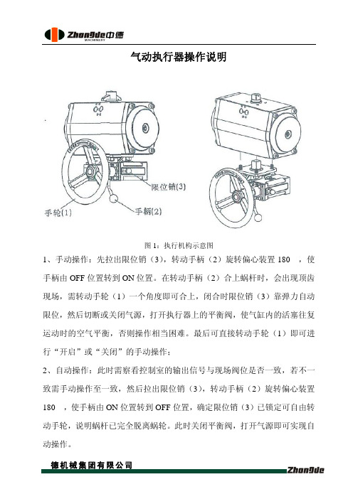
图1:执行机构示意图
1、手动操作:先拉出限位销(3),转动手柄(2)旋转偏心装置180°,使手柄由OFF 位置转到ON 位置。
在转动手柄(2)合上蜗杆时,会出现顶齿现场,需转动手轮(1)一个角度即可合上,闭合时限位销(3)靠弹力自动限位,然后切断或关闭气源,打开执行器上的平衡阀,使气缸内的活塞往复运动时的空气平衡,否则操作相当困难。
最后可直接转动手轮(1)即可进行“开启”或“关闭”的手动操作;
2、自动操作:此时需察看控制室的输出信号与现场阀位是否一致,若不一致需手动操作至一致,然后拉出限位销(3),转动手柄(2)旋转偏心装置180°,使手柄由ON 位置转到OFF 位置,确定限位销(3)已锁定可自由转动手轮,说明蜗杆已完全脱离蜗轮。
此时关闭平衡阀,打开气源即可实现自动操作。
气动执行器METSO说明书
PNEUMATIC CYLINDER ACTUATORSSeries BJ and B1JInstallation, Maintenance andOperating Instructions2Table of Contents1GENERAL. . . . . . . . . . . . . . . . . . . . . . . . . . . 31.1Scope of the manual. . . . . . . . . . . . . . . . . . . . 31.2Structure and operation. . . . . . . . . . . . . . . . . 31.3Actuator markings. . . . . . . . . . . . . . . . . . . . . . 31.4Specifications. . . . . . . . . . . . . . . . . . . . . . . . . . 31.5Recycling and disposal of a rejected actuator. 41.6Safety precautions. . . . . . . . . . . . . . . . . . . . . . 42TRANSPORTATION, RECEPTION ANDSTORAGE. . . . . . . . . . . . . . . . . . . . . . . . . . 53MOUNTING AND DEMOUNTING. . . . . 53.1Actuator gas supply. . . . . . . . . . . . . . . . . . . . . 53.2Mounting the actutor on the valve. . . . . . . . 53.3Operating directions. . . . . . . . . . . . . . . . . . . . 63.4Demounting the actuator from the valve. . . 64MAINTENANCE. . . . . . . . . . . . . . . . . . . . . . . . . 64.1General. . . . . . . . . . . . . . . . . . . . . . . . . . . . . . . 64.2Maintenance of the BJ actuator. . . . . . . . . . . 74.3Maintenance of the BJA actuator. . . . . . . . . . 94.4Changing the BJ actuator into a BJA actuator104.5BJR and BJAR actuators. . . . . . . . . . . . . . . . . 114.6BJV and BJK actuators. . . . . . . . . . . . . . . . . . 124.7BJVA and BJKA actuators. . . . . . . . . . . . . . . 124.8BJ 322 and BJA 322 actuators. . . . . . . . . . . 125MALFUNCTIONS. . . . . . . . . . . . . . . . . . . 136TOOLS. . . . . . . . . . . . . . . . . . . . . . . . . . . . 137ORDERING SPARE PARTS. . . . . . . . . . . 138EXPLODED VIEW AND PARTS LISTS. 148.1Actuators BJ/B1J 8-20. . . . . . . . . . . . . . . . . . 148.2Actuators BJ/B1J 25-32. . . . . . . . . . . . . . . . . 158.3Actuators BJA/B1JA 8-20. . . . . . . . . . . . . . . 168.4Actuator BJA/B1JA 25-32. . . . . . . . . . . . . . . 179DIMENSIONS AND WEIGHTS. . . . . . . . 189.1Actuators BJ/B1J, BJA/B1JA. . . . . . . . . . . . . . 189.2Actuator BJR/B1JR. . . . . . . . . . . . . . . . . . . . . 189.3Mounting face dimensions. . . . . . . . . . . . . . 1910TYPE CODING. . . . . . . . . . . . . . . . . . . . . 20READ THESE INSTRUCTIONS FIRST!These instructions provide information about safe handling and operation of the actuator.If you require additional assistance, please contact the manufacturer or manufacturer’s representative.Addresses and phone numbers are printed on the back cover.SAVE THESE INSTRUCTIONS!Subject to change without noticeAll trademarks are property of their respective owners.1GENERAL1.1Scope of the manualThese instructions provide essential information for the use of Metso Automation BJ and B1J series actuators. For more details about valves, positioners and accessories, refer to the separate installation, operating and maintenance instructions of the par-ticular unit.1.2Structure and operationThe BJ and B1J series actuators are pneumatic cylinder actuators designed for control and shut-off service.The linkage has PTFE, PE-HD and Glacier DU bearings. The robust cast-iron housing efficiently protects the mechanism from ambient dust and moisture.The spring provides the required safety function; the valve either opens or closes if the air supply is interrupted.The mounting face dimensions of the BJ actuator comply with the manufacturer ’s internal standard and those of the B1J with the ISO 5211 standard.In the BJ type, the spring is located on the piston rod side. The secondary shaft of the actuator, operated by the spring, rotates clockwise as seen from the pointer cover side. The piston then moves towards the end of the cylinder. The BJ type is normally applied for the spring-to-close operation, as it normally closes in the clockwise direction. The two keyways in the secondary shaft are positioned at an angle of 90° to each other, making it possible to change the position of the actuator in relation to the valve,see Fig. 1.In the BJA type, the spring is located in the cylinder end side. The secondary shaft, operated by the spring, rotates counter-clock-wise as seen from the pointer cover side. The piston moves away from the cylinder end. The BJA type is used for the spring-to-open function, see Fig. 1.The size of the spring actuator is selected according to the torque given by the spring. It is, however, important to check that there is sufficient supply pressure to give the required torque in the opposite direction.Screws are located in the upper end of the cylinder and in the lower end of the housing to regulate the length of the piston stroke and also the rotation angle of the actuator shaft.1.3Actuator markingsThe actuator is provided with an identification plate, see Fig. 2.Identification plate markings are:1.Type 2. PO number 3.Manufacturing date 4.Checked by 5. Max. supply pressure1.4SpecificationsAmbient temperature:Standard design-20° - + 70°CLow temperature design -40° - + 70°C High temperature design -20° - +120°C Maximum supply pressure:8.5 bar/850 kPa Stroke volume, dm 3(liters):BJ 80,9BJ 101,8BJ 123,6BJ 166,7BJ 2013BJ 2527BJ 3253BJ 322106BJBJAvalve closedvalve open2 keyways2 keywaysopening pressure closing pressurevalve closedvalve openFig. 1.Operating principle of the actuatorFig. 2.Identification plate markings3(5)(1)(2)(4)(3)Nominal torque at maximum supply pressure, Nm:BJ 870BJ 10150BJ 12300BJ 16600BJ 201200BJ 252400BJ 324800BJ 3229600NB. The torque changes according to supply pressure.1.5Recycling and disposal of a rejected actuatorMost actuator parts can be recycled if sorted according to material. Most parts have material marking. A material list is supplied with the actuator. In addition, separate recycling and disposal instructions are available from the manufacturer. An actuator can also be returned to the manufacturer for recycling and disposal against a fee.1.6Safety precautionsCAUTION:Don’t exceed the permitted values!Exceeding the permitted pressure value marked on the actuator may cause damage and lead to uncontrolled pressure release in the worst case. Damage to the equipment and personal injury may result.CAUTION:Don’t dismantle a pressurized actuator!Dismantling a pressurized actuator leads to uncontrolled pressure release. Shut off the supply pressure and release pressure from the cylinder before dismantling the actuator.Otherwise, personal injury and damage to equipment may result.CAUTION:Follow the instructions given on the actuator warning plates!CAUTION:Before opening the cylinder fastening screws,release spring tension directed on actuator warning plate and in these instructions!CAUTION:Don’t operate the actuator manually by turning from the lever arm!CAUTION:Don’t dismantle the spring package!The spring package within the cylinder is preloaded. The lock-welded fastening screw of the piston must never be opened or the spring package dismantled. The piston, piston rod, spring and spring plate of the BJ actuator are always delivered as a pre-assembled package.CAUTION:Don’t use the lever in the torsion arm for manual operation when the actuator is pressurized!Shut off the supply pressure and release pressure from the cylinder before using the hand lever. Note also the dynamic torque caused by the pipe flow.Otherwise, personal injury and damage to equipment may result.CAUTION:Take the weight of the actuator or valve combination into account when handling it!Do not lift the valve combination from the actuator,positioner or limit switch or their piping.Lift the actuator as directed in section 2,lifting ropes for a valve combination should be fastened around it.Weights are listed in the table on page 18.Dropping may result in personal injury or damage to equipment.M β / M Nβ °BJAFig. 3.Output torque a a function of turning angleM β / M Nβ °BJ42TRANSPORTATION, RECEPTION AND STORAGEMake sure that the actuator and associated equipment have not been damaged during transportation. Store the actuator carefully before installation, preferably indoors in a dry place. Do not take it to the installation site or remove the protective caps of ports for piping until just before installation.Lift the actuator as shown in Fig. 4: in a horizontal position from the stop screws, in a vertical position from an eye bolt screwed in the place of a stop screw. Do not use the lug for lifting dual-cylinder actuators. Refer to page 18 for weights.3MOUNTING AND DEMOUNTING 3.1Actuator gas supplyDry compressed air or natural gas can be used in actuators in open-close operation, no oil spraying is needed. Clean, dry and oil-free instrument air must be used for cylinder actuators with a positioner. The air supply connections are presented in the dimensional drawings on page 18. The maximum supply pressure is 8.5 bar.3.2Mounting the actutor on the valveCAUTION:Take the weight of the actuator or valve combination into account when handling it!CAUTION:Beware of the cutting movement of the valve!Install the actuator so that the shaft of the valve or any other device to be actuated goes into the shaft bore of the actuator.If the bore is larger than the shaft diameter, use a collar in between. The actuator shaft bore has two keyways at an angle of 90°. These allow the installation position of the actuator to be changed in relation to the valve. Metso Automation valves have a bevel at the end of their shafts to facilitate installation.The installation position can be selected freely, but Metso Automation recommends installation with the cylinder upright.The actuator is thus best protected against damage due to supply air impurities or water.When the installation position of the actuator is altered, the arrow indicating the operating direction must be turned to correspond with the actual operation of the valve.When necessary, lubricate the actuator bore and collar with Cortec VCI 369 or an equivalent anti-corrosive agent to prevent it from jamming due to rust.The actuator must not be allowed to come in contact with the pipework, because the vibrations may damage it or cause unsat-isfactory operation.In some cases, e.g. when using large actuators or with extensive pipework vibrations, the actuator should be supported. Consult Metso Automation for instructions.If the actuator is used with devices other than Metso Automation valves, any additional parts attached to the actuator must beproperly protected.Fig. 4.Lifting the actuatorFig. 5.Ways to install the actuator53.3Operating directions A sticker on the actuator cylinder indicates the spring action direction.NOTE:Separate instructions are available for adjusting the close limit of metal-seated butterly valves. Refer to the installation,operating and maintenance instructions of the valve.3.3.1BJ actuator -spring-to-close directionInstall the actuator on the valve with the piston in the upper end of the cylinder and the valve in the closed position, see Fig. 6.The cylinder must be depressurized and the air ports open.Adjust the closed-position setting using the stop screw (26) at the end of the cylinder. Seal the screw thread with a non-hard-ening sealant, such as Locktite 225 or the equivalent. The open-position setting is adjusted with the stop screw (27) at the bottom of the housing while the actuator is pressurized and the piston is in the lower position.3.3.2BJA actuator -spring-to-open directionInstall the actuator on the valve with the piston in the lower end of the cylinder and the valve in the open position, see fig 7. The cylinder must be unpressurized and the air ports open. Adjust the open-position setting using the stop screw (27) at the end of the cylinder. The close-position setting is adjusted with the stop screw (26) at the end of the cylinder while the actuator is pressurized and the piston is in the upper position.3.4Demounting the actuator from the valveCAUTION:Take the weight of the actuator or valve combination into account when handling it!CAUTION:Beware of the cutting movement of the valve!The actuator must be depressurized and the supply air pipes disconnected. Unscrew the actuator-side screws of the bracket and pull the actuator off the valve shaft. This is best done using a specific extractor, see fig 8 and section 6 ’Tools ’.Note the mutual positioning of the valve and the actuator to ensure correct functioning after reassembly.4MAINTENANCE 4.1GeneralCAUTION:Note the precautions in section 1.6 before beginning work!Under normal conditions, the actuators do not need regular maintenance. Maintenance procedures that the end user can do himself when necessary are described below.Unless stated otherwise, the part numbers given refer to the exploded view and parts list in section 8.In especially harsh corrosive conditions the linkage system inside the housing must be lubricated every six months. Use Cortec VCI 369 anti-corrosive agent or the equivalent. The housing may also be half filled with semi-fluid water-resistant grease (e.g.Mobilux EP2) while the piston rod is in the lower position.If you remove the stop screw, adjust the limits after lubrication or grease filling !2 keyways Closed-position stop screwOpen position stop screw80°90°Fig. 6.BJ actuator2 keyways Closed-position stop screwOpen position stop screw80°90°Fig. 7.BJA actuatorFig. 8.Removing the actuator with an extractor64.2Maintenance of the BJ actuatorCAUTION:Don ’t dismantle a pressurized actuator!CAUTION:To release spring tension, the stop screw at the end of the cylinder must be removed before the cylinder fastening screws are opened!CAUTION:Don ’t dismantle the spring package!The spring package within the cylinder is preloaded. Never open the lock-welded fastening screw of the piston or dismantle the spring package. The piston, piston rod, spring and spring plate of the BJ actuator are always delivered as a pre-assembled package.The cylinder has a warning plate (43). When servicing the unit, check that the plate is in place and legible. See Fig. 9. Also check that thecylinder has the arrow sticker indicating the spring operating direction.4.2.1Replacment of piston sealsWe recommend that all seals and soft bearings be replaced whenthe actuator has been dismantled for servicing.Detach the actuator.Check that the cylinder has been depressurized, and the piston is at the outermost end of the cylinder.Remove the cylinder end side stop screw (26).Remove cylinder end (44).Remove housing cover (2).Unscrew the bearing screw (29) and the cylinder fastening screws (31) from the cylinder base (6) side, see Fig. 10. If the piston turns, do not prevent the turning with the piston fastening nut; send the entire actuator to the manufacturer to be repaired. It is very dangerous if the lock welding of the piston fastening nut is broken!Remove the cylinder with the piston - do not dismantle the spring package!Remove the O-rings.Slide the piston out of the cylinder.Remove old seals and O-rings (24, 18).Remove piston rod seal (16) and bearing (22). Clean the seal space.Lubricate seal space and new O-ring with Unisilikon L250L or Molykote III. Install new bearing and O-ring, see fig 11.Clean piston seal groove and apply a thin coat of Cortec VCI 369.Install the O-ring (18) located under the piston seals.Place piston seals (24) around the piston so that the ends of the strips are located at opposite sides. Tighten the strips with a tie ring as in Fig. 12. Strips indicated with an asterisk can be cut 1.5 to 3 mm shorter to facilitate assembly.NOTE:The inside surface of the cylinder must be free of any grease!1824BJ 8-251824BJ 32Fig. 9. Warning plate of the BJ actuatorFig. 10.Opening the fastening screw of the actuator bearing unit(22)Press the bearing strip like this to facilitate installation(16)Fig. 11. Mounting the piston rod bearing and seal*)*)*)Fig. 12.Tightening piston seals with a tie ring7Hammer or press the piston into the cylinder through the tie ring. Note the indicator arrow direction. See Fig. 13.Install new O-rings (19). Replace cylinder end and install cylinder with piston. Note the location of the air supply port:it must correspond to the exhaust air port in the cylinder base. Tighten screws (31); the torque is given in table 1.Apply bearing unit screw (29) thread with a sealant, e.g.Locktite 225, and tighten the screw as in table 1.Fasten the housing cover temporarily so that the secon-dary shaft bearings function but the linkage can still be seen, see Fig. 14.CAUTION:Keep your fingers, tools or other items out of the housing while operating the actuator with the cover open!Check the attachment of the end and the base before temporarily connecting the compressed air supply to the actuator with a shut-off valve.Operate the actuator to check cylinder function and the condition of linkage bearings. Close the air supply and depressurize the cylinder.Lubricate the linkage throughout with Cortec VCI 369anti-corrosive agent.Apply sealant, e.g. Loctite 573, to the interface between housing and cover and fasten the cover. See table 1 for torque.Install the actuator on the valve and adjust the stop screws.To remove the cylinder base, you will need a special tool for opening the lock nut, see section 6 ’Tools ’.4.2.2Replacement of linkage bearings and O-ringsDetach actuator from valve.Check that the cylinder has been depressurized, and the piston is at the outermost end.Remove cylinder end side stop screw (26).Remove housing cover (2).Open bearing unit (5) fastening screw (29). See Fig. 10.Turn lever arm (3) to detach the bearing unit from the piston rod (10). Lift the entire linkage out of the housing.See Fig. 15.Remove lock rings (36) and support rings (37). See Fig.16.Remove connection arms (4) and check the condition of the bearings (20, 21).Torque, Nm Item 2829303135Actuator BJ 8BJ 10BJ 12BJ 16BJ 20BJ 25BJ 3290901803007001100200035901803007001100200088121220307018408080802002501501802002504008001500Table 1.Tightening torques for screwsFig. 13.Placing the piston in the cylinderFig. 14.Mounting the cover on the housing Fig. 15.Removing the linkage from the housingFig. 16.Dismantling the linkage8The connection arm (4) bearings (20, 21) of the BJ8-25 actuator are fastened with a press-on fit, and therefore the entire connec-tion arm must be replaced instead of changing the bearings. In the BJ32 actuator, the bearings can be removed.Remove lever arm bearings (23) and O-rings (17).Clean the linkage parts and apply Cortec VCI 369 to bearing and seal surfaces.Install new lever arm bearings and O-rings.Assemble the linkage and install in the housing; the correct position is shown in Fig. 15.Apply sealant, e.g. Locktite 225, to the bearing unit screw (29) thread and tighten the screw as in table 1.Lubricate the linkage throughout with Cortec VCI 369anti-corrosive agent.Apply sealant, e.g. Loctite 573, to the interface between housing and cover and fasten the cover. See table 1 for torque.Operate the actuator to check that it is moving properly.Install the actuator on the valve and adjust the stop screws.In a corrosive environment with high ambient humidity the linkage must be lubricated with Cortec VCI 369 every six months or the housing filled with grease. See section 4.1.4.3Maintenance of the BJA actuatorCAUTION:Don ’t dismantle a pressurized actuator!CAUTION:To release spring tension, always remove the stop screw at the bottom of the housing before opening the cylinder fastening screws !The cylinder has a warning plate (43), see fig 17. When servicing the unit, check that the plate is in place and legible. Also check that the cylinder has the arrow sticker indicating the spring operating direction.CAUTION:Don ’t dismantle the spring package!The spring pack within the cylinder is preloaded. Never open the lock-welded fastening screw or the piston or dismantle the spring package. The piston, piston rod, spring and spring plate of the BJA actuator are always delivered as a pre-assembled package.4.3.1Replacement of piston sealsWe recommended that all seals and soft bearings be replaced when the actuator has been dismantled for servicing.Detach the actuator from the valve.Check that the cylinder has been depressurized, and the piston is at the cylinder base end.Remove the cylinder base side stop screw (27).Remove cylinder fastening screws (31) from the cylinder base (6) side. Lift the cylinder off together with the end.Remove housing cover (2).Turn the linkage enough to expose the bearing unit fastening screw (29). Open the screw.Remove the piston with the spring package - do not dismantle the spring package!Remove old seals and the O-ring (24, 18).Remove piston rod seal (16) and bearing (22). Clean the seal space.Lubricate seal space and new O-ring with Unisilikon L250L or Molykote III. Install new bearing and O-ring, see fig 11.Clean piston seal groove and apply a thin coat of Cortec VCI 369.Install the O-ring (18) located under the piston seals.Place piston seals (24) around the piston so that the ends of the strips are at opposite sides. Tighten the strips with a tie ring as in Fig. 18. Strips indicated with an asterisk can be cut 1.5 to 3 mm shorter to facilitate assembly.NOTE:The inside surface of the cylinder must be free of any grease!Fig. 17.BJA actuator warning plateFig. 18.Tightening piston seals with the tie ring1824BJA 8-25*)1824BJA 32*)*)9Hammer or press the piston into the cylinder through the tie ring. Note the indicator arrow direction. See Fig. 19.Install new cylinder base O-rings (19). Replace cylinder with piston.Apply sealant, e.g. Locktite 225, to the bearing unit screw (29) thread and tighten the screw as in table 1 before mounting onto cylinder base.Fasten the housing cover temporarily so that the secon-dary shaft bearings function but the linkage can be seen.CAUTION:Keep your fingers, tools or other items out of the housing while operating the actuator with the cover open!Check the attachment of the end and the base before temporarily connecting the compressed air supply to the actuator with a shut-off valve.Operate the actuator to check cylinder function and the condition of bearings. Close the air supply and depressur-ize the cylinder.Lubricate the linkage throughout with Cortec VCI 369anti-corrosive agent.Apply sealant, e.g. Loctite 573, to the interface between housing and cover and fasten the cover. See table 1 for torque.To remove the cylinder base, you will need a special tool for opening the lock nut, see section 6 ’Tools ’. When reinstalling,secure the nut with Loctite 225.Install the actuator on the valve and adjust the stop screws.4.3.2Replacement of linkage bearings and O-ringsCAUTION:For reasons of safety, follow the work procedure given below exactly.Detach actuator from valve.Check that the cylinder has been depressurized, and the piston is at the cylinder base end.Remove cylinder base stop screw (27).Remove housing cover (2).Open cylinder fastening screws (31) from the base side.Lift cylinder and piston until the bearing unit fastening screw (29) can be opened.Open fastening screw. See Fig. 10.Turn lever arm (3) to detach the bearing unit (5) from the piston rod. Lift the entire linkage out of the housing. See Fig. 15.Remove lock rings (36) and support rings (37). See Fig. 16.Remove connection arms (4) and check the condition of the bearings (20, 21).The connection arm (4) bearings (20, 21) of the BJ8-25 actuator are fastened with a press-on fit, and so the entire connection arm must be replaced instead of changing the bearings. In the BJ32actuator, the bearings can be removed.Remove lever arm bearings (23) and O-rings (17).Clean linkage parts and apply Cortec VCI 369 to bearing and seal surfaces.Install new lever arm bearings and O-rings.Assemble the linkage and install in the housing.Apply sealant, e.g. Locktite 225, to bearing unit screw (29)thread and tighten the screw as in table 1.Install new cylinder base O-ring (19). Install the cylinder.Apply Cortec VCI 369 anti-corrosive agent to the linkage throughout.Apply sealant, e.g. Loctite 573t, to the interface between housing and cover, and fasten the cover.Operate the actuator to check that it is moving properly.Install the actuator on the valve and adjust the stop screws.In a corrosive environment with high ambient humidity the linkage must be lubricated with Cortec VCI 369 about every six months, or the housing filled with grease. See section 4.1.4.4Changing the BJ actuator into a BJA actuatorThe BJ actuator can be changed into a BJA actuator by replacing the spring package and turning the cylinder the other way around.4.4.1Removing the cylinderRemove the cylinder as in section 4.2.1.4.4.2Changing the spring packageReplace the spring package of the BJ actuator with a BJA spring package ordered from the manufacturer. The cylinder must be turned 180°. See Fig. 20.NOTE:The warning plate of the cylinder must also be changed tocorrespond with the BJA actuator!Fig. 19.Placing the piston in the cylinderFig. 20.Turning the cylinder104.4.3Assembling the actuatorAssemble the actuator as in section 4.3.1.4.5BJR and BJAR actuators4.5.1BJR actuatorThe BJR actuator is otherwise like the BJ except that it can be operated manually to bring the piston to the lower position against the spring in case there is no air supply. The BJ actuator can be changed into a BJR by replacing the cylinder end (44) accordingly and adding parts (50 to 56).4.5.1.1MaintenanceCAUTION:To release spring tension, always remove the threaded spindle and spindle nut at the cylinder end before opening the cylinder fastening screws!The cylinder has a warning plate (43), see fig 21. When servicing the unit, check that the plate is in place and legible. Also check that the cylinder has the arrow sticker indicating the spring operating direction.If air escapes between the spindle (50) and spindle nut (51), check the O-ring (54) and replace it if necessary. Also check the condition of the cylindrical rollers (56). See Fig. 22. Other maintenance as described for the BJ actuator in section 4.2.Parts list for Fig. 22:Part Quantity Name501Spindle511Spindle nut521Hand wheel531Lock nut541O-ring551Spring pin561Cylindrical roller4.5.1.2Valve close and open position adjust-mentIn the BJR actuator, unlike in the BJ, the upper valve position limit is adjusted with the spindle nut (51) secured with the lock nut (53). During adjusting, the spindle (50) must be in the extreme outer position.4.5.2BJAR actuatorThe BJAR actuator is otherwise like the BJA, except that it can be operated manually to bring the piston to the upper position against the spring in case there is no air supply. The BJA actuator can be changed into a BJAR by replacing the housing (1) and adding parts (50 to 56), see Fig. 24.To make the change, the actuator must be dismantled, see section 4.3.2. A special tool is needed to unscrew and fasten the lock nut (35) fastening the cylinder base to the housing. See chapter 6 ’Tools’.4.5.2.1MaintenanceCAUTION:To release spring tension, always remove the threaded spindle and spindle nut at the cylinder end before opening the cylinder fastening screws!The cylinder has a warning plate (43). When servicing the unit, check that the plate is in place and legible, see Fig. 23. Also check that the cylinder has the arrow sticker indicating the springoperating direction.If stiffness or noise occurs when the actuator is operated with thehandwheel, check the condition of the bearings (56), see Fig. 24.Other maintenance as described for the BJA actuator in section 4.3. Fig. 21.BJR actuator warning plateFig. 22.BJR actuatorFig. 23.BJAR actuator warning plate11。
气动执行器工作原理
气动执行器工作原理
气动执行器是一种利用气压驱动来完成物体运动的装置。
其工作原理可以分为三个部分:气源、控制系统和执行器。
首先,气源提供了气体压力,通常使用压缩空气或气体瓶。
气源通过管道将气体传输到控制系统中。
接下来,控制系统根据输入的信号来控制气体的流动。
常见的控制系统有电磁阀、脚踏阀或手动阀等。
当接收到控制信号时,控制系统打开或关闭相应的阀门,控制气体的流动。
最后,执行器将气体压力转化为机械力来驱动物体运动。
执行器通常由气缸和阀门组成。
当气缸接收到气体压力时,气缸内部的活塞会移动,从而产生机械力。
通过控制阀门的开启和关闭,可以控制气缸的运动方向和速度。
总结来说,气动执行器的工作原理是通过气源提供气体压力,控制系统控制气体流动,最后由执行器将气体压力转化为机械力来驱动物体运动。
通过合理的控制和调节,可以实现准确和可靠的运动控制。
三段式气动执行器使用说明

三段式气动执行器使用说明
三段式气动执行器是一种常用于工业自动化控制系统中的执行器,主要用于控制阀门、门窗等设备的开闭。
该执行器由三个部分组成:气缸、齿轮箱和输出轴。
气缸接收气源,通过气压控制齿轮箱的运转,进而驱动输出轴实现设备的开闭。
第二段:使用方法
1. 安装:将三段式气动执行器安装在需要控制的设备上,并连接好气源和控制信号线。
2. 调试:在接通气源前,请确保输出轴处于关闭状态。
接通气源后,通过控制信号线发送信号,使气缸接收到气压并推动齿轮箱转动,从而驱动输出轴实现设备的开启。
3. 维护:定期检查气源和控制信号线是否正常,清理齿轮箱和输出轴,确保三段式气动执行器的正常运转。
第三段:注意事项
1. 在使用前,请确认执行器的型号、规格是否与所需应用相符。
2. 在使用过程中,注意避免过度冲击和振动,以免影响执行器的稳定性和寿命。
3. 请勿将气动执行器用于超过其额定负载的场合,以免造成气缸、齿轮箱等部件的损坏。
4. 请勿将气动执行器暴露在潮湿、高温或腐蚀环境中,以免影响其正常运转。
5. 使用前请仔细阅读说明书,并按照说明操作。
如有任何疑问,
请咨询专业人士。
- 1、下载文档前请自行甄别文档内容的完整性,平台不提供额外的编辑、内容补充、找答案等附加服务。
- 2、"仅部分预览"的文档,不可在线预览部分如存在完整性等问题,可反馈申请退款(可完整预览的文档不适用该条件!)。
- 3、如文档侵犯您的权益,请联系客服反馈,我们会尽快为您处理(人工客服工作时间:9:00-18:30)。
气动执行器
气动执行器俗称气动头
执行器按其能源形式分为气动,电动和液动三大类,它们各有特点,适用于不同的场合。
气动执行器是执行器中的一种类别。
气动执行器还可以分为单作用和双作用两种类型:执行器的开关动作都通过气源来驱动执行,叫做DOUBLE ACTING (双作用)。
SPRING RETURN (单作用)的开关动作只有开动作是气源驱动,而关动作是弹簧复位。
气动执行器简介
气动执行器的执行机构和调节机构是统一的整体,其执行机构有薄膜式、活塞式和齿轮齿条式。
活塞式行程长,适用于要求有较大推力的场合;而薄膜式行程较小,只能直接带动阀杆。
由于齿轮齿条式气动执行机构有结构简单,输出推力大,动作平稳可靠,并且安全防爆等优点,在发电厂、化工,炼油等对安全要求较高的生产过程中有广泛的应用。
齿轮齿条式:
齿轮齿条
内部结构
薄膜式:
活塞式
气动执行器的缺点
控制精度较低,双作用的气动执行器,断气源后不能回到预设位置。
单作用的气动执行器,断气源后可以依靠弹簧回到预设位置
工作原理说明
当压缩空气从A管咀进入气动执行器时,气体推动双活塞向两端(缸盖端)直线运动,活塞上的齿条带动旋转轴上的齿轮逆时针方向转动90度,阀门即被打开。
此时气动执行阀两端的气体随B管咀排出。
反之,当压缩空气从B官咀进入气动执行器的两端时,气体推动双塞向中间直线运动,活塞上的齿条带动旋转轴上的齿轮顺时针方向转动90度,阀门即被关闭。
此时气动执行器中间的气体随A管咀排出。
以上为标准型的传动原理。
根据用户需求,气动执行器可装置成与标准型相反的传动原理,即选准轴顺时针方向转动为开启阀门,逆时针方向转动为关闭阀门。
单作用(弹簧复
位型)气动执行器A管咀为进气口,B管咀为排气孔(B管咀应安装消声器)。
A管咀进气为开启阀门,断气时靠弹簧力关闭阀门。
特点
紧凑的双活塞齿条式结构,啮合精确,效率高,输出扭矩恒定。
铝制缸体、活塞及端盖,与同规格结构的执行器相比重量最轻。
缸体为挤压铝合金,经硬质阳极氧化处理,内表面质地坚硬,强度,硬度高。
采用低摩擦材料制成的滑动轴承,避免了金属间的相互直接接触,摩擦系数低,转动灵活,使用寿命长。
气动执行器与阀门连接符合ISO5211标准
气源孔符合NAMUR 标准。
气动执行器底部轴装配孔(符合ISO5211标准)成双四方形,便于带方杆的阀线性或45°转角安装。
输出轴的顶部和顶部的孔符合NAMUR 标准。
两端的调整螺钉可调整阀门的开启角度。
相同规格的有双作用式、单作用式(弹簧复位)。
可根据阀门需要选择方向,顺时针或逆时针旋转。
根据用户需要安装电磁阀、定位器(开度指示)、回信器、各种限位开关及手动操作装置。
气动执行器分类
执行器按其能源形式分为气动,电动和液动三大类,它们各有特点,适用于不同的场合。
气动执行器是执行器中的一种类别。
气动执行器还可以分为单作用和双作用两种类型:执行器的开关动作都通过气源来驱动执行,叫做DOUBLE ACTING (双作用)。
SPRING RETURN (单作用)的开关动作只有开动作是气源驱动,而关动作时弹簧复位。
[1]气动执行器的选型
注:本文均以DA/SR系列气动执行机构为例,说明执行机构的选用这个参考资料的目的是帮助客户正确选择执行机构,在把气动/电动执行机构安装到阀门之前,必须考虑以下因素。
* 阀门的运行力矩加上生产厂家的推荐的安全系数/根据操作状况。
* 执行机构的气源压力或电源电压。
* 执行机构的类型双作用或者单作用(弹簧复位)以及一定气源下的输出力矩或额定电压下的输出力矩。
* 执行机构的转向以及故障模式(故障开或故障关)正确选择一个执行机构是非常重要的,如执行机构过大,阀杆可能受力过大。
相反如执行机构过小,侧不能产生足够的力矩来充分操作阀门。
一般地说,我们认为操作阀门所需的力矩来自阀门的金属部件(如球芯,阀瓣)和密封件(阀座)之间的磨擦。
根据阀门使用场合,使用温度,操作频率,管道和压差,流动介质(润滑、干燥、泥浆),许多因素均影响操作力矩
球阀的结构原理基本上根据一个抛光球芯(包括通道)包夹在两个阀座这间(上游
和下游),球心的旋转对流体进行拦截或流过球芯,上游和下游的压差产生的力使球芯紧靠在下游阀座(浮动球结构)。
这种情况下操作阀门的力矩是由球芯与阀座、阀杆
与填料相互摩擦所决定的。
如图1所示,力矩最大值发生在出现压差且球芯在关闭位置向打开方向旋转时
蝶阀。
蝶阀的结构原理基本上根据固定在轴心的蝶板。
在关闭位置蝶板与阀座完全密封,当蝶板旋转(绕着阀杆)后与流体的流向平行时,阀门处于全开位置。
相反当蝶板与流体的流向垂直时,阀门处于关闭位置。
操作蝶阀的力矩是由蝶板与阀座、阀杆与填料之间的磨擦所决定的,同时压差作用在蝶板上的力也影响操作力矩如阀门在关闭时力矩最大,微小地旋转后,力矩将明显减小
旋塞阀的结构原理是基本根据密封在锥形塞体里的塞子。
在塞子的一个方向上有一个通道。
随着塞子旋入阀座来实现阀门的开启和关闭。
操作力矩通常不受流体的压力影响而是由开启和关闭过程中阀座和塞子之间的摩擦所决定的。
阀门在关闭时力矩最大。
由于有受压力的影响,在余下的操作中始终保持较高的力矩
双作用执行机构的选用以DA系列气动执行机构为例
齿轮条式执行机构的输出力矩是活塞压力(气源压力所供)乘上节圆半径(力臂)所得,如图4所示。
且磨擦阻力小效率高。
如图5所示,顺时针旋转和逆时针旋转时输出力矩都是线性的。
在正常操作条件下,双作用执行机构的推荐安全系数为25-50% 单作用执行机构的选用
以SR系列气动执行机构为例在弹簧复位的应用中,输出力矩是在两个不同的操作过程中所得,根据行程位置,每一次操作产生两个不同的力矩值。
弹簧复位执行机构的输出力矩由力(空气压力或弹簧作用力)乘上力臂所得第一种状况:输出力矩是由空气压力进入中腔压缩弹簧后所得,称为"空气行程输出力矩"在这种情况下,气源压力迫使活塞从0度转向90度位置,由于弹簧压缩产生反作用力,力矩从起点时最大值逐渐递减直至到第二种状况:输出力矩是当中腔失气时弹簧恢复力作用在活塞上所得,称为"弹簧行程输出力矩"在这种情况下,由于弹簧的伸长,输出力矩从90度逐渐递减直0度如以上所述,单作用执行机构是根据在两种状况下产生一个平衡力矩的基础上设计而成的。
如图11所示。
在每种情况下,通过改变每边弹簧数量和气源压力的关系(如每边2根弹簧和5.5巴气源或反之),有可能获得不平衡力矩在弹簧复位应用中可获得两种状况:失气开启或失气关闭。
在正常工作条件下,弹簧复位执行机构的推荐安全系数为25-50%
弹簧复位执行机构的选用示例(同时见技术数据表):
弹簧关(失气)
*球阀的力矩=80NM
*安全系数(25%)=80NM+25%=100NM
*气源压力=0.6MPa
被选用的SY-SR执行机构是SR125-05,因为可产生下列数值:
*弹簧行程0o=119.2NM
*弹簧行程90o=216.2NM
*空气行程0o=228.7NM
*空气行程90o=118.8NM。