autonics旋转编码器中文选型手册及说明书
DC 2线系列(中文)

约 约
约 约 约
约 约 约
约 约 约
约
并列安装
重量不含包装盒.
外形尺寸图
区分
配线引出型 接插型 配线引出接插型
单位
配线引出型
设定距离设定方法
被测物体 被测物体 移动方向
警告
用于人身及财产上影响大的机器 如:核能控制、医疗器械、车辆、铁路、航空、 易燃装置、娱乐设施及安全装置时 务必加装双重安全措施 否则易引发火灾、人身伤亡及财产损失 请连接负载后再接电源 否则会损坏内部元件
周围金属的影响
若接近传感器周围有金属,受其影响会引起复位不良,为避免因周围金属引起误动作, 安装时最小尺寸如下表所示。
并列安装
非常感谢您选择Autonics的产品 为了您的安全,请在使用前阅读以下内容 注意安全
注意安全 是为安全正确使用产品,预防事故及危险发生,请务必遵守 注意安全中 警告 和 注意 两种意思如下
保存温度
使用环境湿度
保护电路 防护等级 材质 获得认证 重量
浪涌保护电路
浪涌保护电路,过电流保护电路
规格
外壳/螺母:黄铜,镀镍处理,垫片:铁,镀镍处理,检测面:耐热ABS 一般型线(黑色):聚氯乙烯(PVC),耐油型强化线(灰色):聚氯乙烯(耐油强化PVC)
型号名 项目 相对安装
警告 如果不按照说明操作会引发严重伤亡 注意 如果不按照说明操作会导致轻微伤害及产品损伤
后端 后端 力矩 (8.82N m)
(3.92N m)
(6.37N m) (11.76N m) (1.47N m) (49N m) 表 (78.4N m)
数字 圆柱形 方形
单位:mm 检测面的直径(mm) 检测面(正方形)的边长(mm) 直流2线型 直流2线式电缆输出接插型 直流2线式接插型 圆柱型 方型 高频振荡型接近传感器 规格是配线一般型2,000mm,配线一般接插型300mm。 式样是 3.5,2芯(导体截面积:0.2mm ,绝缘面直径
旋转编码开关(RotaryEncoderswitch)使用说明及程序
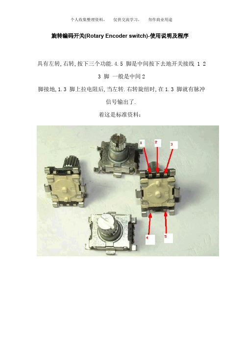
旋转编码开关(Rotary Encoder switch)-使用说明及程序具有左转,右转,按下三个功能.4.5 脚是中间按下去地开关接线 1 23 脚一般是中间2脚接地,1.3 脚上拉电阻后,当左转.右转旋纽时,在1.3 脚就有脉冲信号输出了.着这是标准资料:在单片机编程时,左转和右转地判别是难点,用示波器观察这种开关左转和右转时两个输出脚地信号有个相位差,见下图:由此可见,如果输出1 为高电平时,输出2 出现一个高电平,这时开关就是向顺时针旋转; 当输出1 为高电平,输出2 出现一个低电平,这时就一定是逆时针方向旋转.所以,在单片机编程时只需要判断当输出1 为高电平时,输出2 当时地状态就可以判断出是左旋转或是右旋转了.还有另外一种3 脚地,除了不带按钮开关外,和上面是一样地使用.参考:#include "reg51.h"#define uint unsigned intsbit CodingsWitch_A=P1_1;sbit CodingsWitch_B=P1_2;uint CodingsWitchPolling()//{static Uchar Aold,Bold; //定义了两个变量用来储蓄上一次调用此方法是编码开关两引脚地电平static Uchar st; //定义了一个变量用来储蓄以前是否出现了两个引脚都为高电平地状态uint tmp = 0;if(CodingsWitch_A&&CodingsWitch_B)st = 1; //if(st) //如果st 为1 执行下面地步骤{if(CodingsWitch_A==0&&CodingsWitch_B==0) //如果当前编码开关地两个引脚都为底电平执行下面地步骤{if(Bold) //为高说明编码开关在向加大地方向转{st = 0;tmp++; //}if(Aold) //为高说明编码开关在向减小地方向转{st = 0;tmp--; //设返回值}}}Aold = CodingsWitch_A; //Bold = CodingsWitch_B; //储return tmp; //}//编码器计数程序void encoder_cnt(void){uchar temp;temp = PIND; //取端口D 管脚信号couch_clr = (temp & 0x08); //取编码器清零信号if(couch_clr != false) //有编码器清零信号{couch_num = 0; //水平床码清零}else{if(encoder_cnt_en == false) //编码器计数模块没有启动{pr_couch_ba = temp & 0x03; //取编码器A.B 相电平信号}else{couch_ba = temp & 0x03; //取编码器A.B 相电平信号if(pr_couch_ba == 0x00){if(couch_ba == 0x01){couch_num++; //水平床码加1}else if(couch_ba == 0x10){couch_num--; //水平床码减1}}else if(pr_couch_ba == 0x01){if(couch_ba == 0x11){couch_num++; //水平床码加1}{couch_num--; //水平床码减1}}else if(pr_couch_ba == 0x10){if(couch_ba == 0x00){couch_num++; //水平床码加1}else if(couch_ba == 0x11){couch_num--; //水平床码减1}}else if(pr_couch_ba == 0x11){if(couch_ba == 0x10){couch_num++; //水平床码加1}{couch_num--; //水平床码减1}}}pr_couch_ba = couch_ba;}}编码器及其计数模块原理飘扬地旋转编码器地检测程序(MCS51)//旋转编码器检测程序,A/B信号分别接在了INT0和INT1上//程序作者:BG4UVR//2005 年1 月15 用KEIL编译.硬件测试通过//注意:编码器地信号,程序未做消抖处理.测试中,A/B信号上各//接了一只104地瓷片电容,工作很正常.如果不接电容,请自行编//写信号消抖程序.#include <at89x51.h>sbit led="0xB1";//有一只LED接在了RXD 引脚上,用来指示正反转;main(){EA=1; //总中断允许EX0=1; //外部中断0允许IT0=1; //外部中断0为边沿触发方式while(1);;}/*********************编码器中断函数入口:无出口:无*********************/void encoder(void) interrupt 0 { //外部中断0if (INT1){led=1;}else{led=0;}}whimsy 地AVR 程序//外部中断0,用于编码开关解码,解码图: A 接中断脚(AVR 地PD2),以此为基准,B 用来判断方向(连到AVR 地PA1), C 接地//A -|// | -----|__________|----------|____________//C -|////B -|// | ----------|__________|----------|____________//C -|// CW ===>>> ROTATION//外部中断设置(ISC01=0,ISC00=1): INT0 引脚上任意地逻辑电平变化都将引发中断#pragma interrupt_handler int0_isr:2void int0_isr(void){//external interupt on INT0GICR=0; //禁止外部中断if ((PIND & 0x04)==0) //先判断是高电平产生地中断还是低点平地中断if ((PINA & 0x02)==0) //再判断B 线上地电平{keycounter--;keydirection="0";}个人收集整理资料,仅供交流学习,勿作商业用途else{keycounter++;keydirection="1";}elseif ((PINA & 0x02)==0){keycounter++;keydirection="1";}else{keycounter--;keydirection=0;}GICR=0x40;}。
奥托尼克斯 CT6-2P 计数器 计时器 中文说明书

型号构成计数器没有规格面板标注过程值显示红色计数值计数器计数器过程时间计时器计时器设定符号设定符号高度高度值显示黄/绿值值检查值检查值,单段单段双段双段和它的显示变化和它的显示变化锁键显示输出的动作表示输出动作表示计数器动作表示计时器动作当计时器动作时闪烁键键键键将改变为和的输出,在没时。
在中。
中。
在键在中尺寸接线图信号当当信号在计数器动作时,信号在计数器动作时,禁止计数输入计时停止接点输入的连接在选择无电压输入的状态输入连接输入逻辑输入逻辑无电压输入电压输入固态输入固态输入标准传感器标准传感器型传感器型传感器接点输入接点输入输出连接连接输出固态输出固态输出连接使用合适的负载和电源,固态输出不能过度ON/OFF,容量以内确认电源没有接反。
当使用感性负荷时继电器等滤波电路二极管,变阻器等必须连接在负荷两端。
计时/计数器非常感谢您选择AUTONICS的产品为了您的安全,请在使用前阅读以下的内容注意安全1. 在以下情况下使用这个设备,如(核能控制,医疗设备,汽车,火车,飞机,航空,娱乐或 安全装置等),需要安装安全保护装置,或联系我们索取这方面的资料. 否则会引起严重的损失,火灾或人身伤害.必须要安装面板.否则可能会发生触电.否则可能会发生触电.在供电状态中不要接触接线端子.不要随意拆卸和改动这个产品,如确实需要请联系我们.否则会引起触电和火灾.否则会引起火灾.请在连接电源线或信号输入时检查端子号. 这个装置不能使用在户外. 否则会缩短此产品的使用寿命或发生触电事故.当电源输入端或信号输入端接线时, 螺丝拧到端子上的力矩为--否则可能会发生损坏或连接端子起火.请遵守额定的规格.否则会缩短这个产品的寿命后发生火灾.清洁这个产品时,不要使用水或油性清洁剂.否则会发生触电或火灾,也将损坏本产品.在易燃易爆,潮湿,太阳光直射,热辐射,振动等场所应避免使用这个单元.否则可能会引起爆炸.在这个单元中不能有流尘或沉淀物.否则可能会引起火灾或机械故障.以上规格如有变化,不另行通知.双预设功能。
SICK增量旋转编码器选型手册

43.1 (1.70)
Ø 60 (2.36) 3 x 120°
Ø0.05 C
其它公差遵循DIN ISO 2768-mk标准 电缆直径- =5.6±0.2mm 弯曲半径 R=30mm
3 x M4 (6-deep)
Ø 48±0.05 (1.89)
夹紧法兰型外形尺寸图,M12 或 M23 插头式
3 x M4 Ø 48±0.05 (1.89) (6-deep)
01000 01024 01250
00200 02048
B型-可选择的分辨率 00050 00100 00200 00250
00300 00314 00360
00500 00512 00720
01000 01024 01250
00200 02048 02500 03600
04000 04096 05000
外壳防护等级IEC60529
质量 EMC5)
DFS60 实心轴,夹紧法兰型 O/ 60mm O/ 10 x 19 mm 0,5 Ncm 0,3 Ncm 6,2 gcm2
5 x 10⁵ rad/s2 径向 轴向 3 x 10⁹ 圈
90% 冲击3) 振动4) 外壳部分 实心轴部分 0.3kg
E
10,000 min-1 80 N 40 N
DFS60全系列产 品
DFS60夹紧法 兰型 外形 尺 寸 : 10× 19mm
DFS60伺服法 ቤተ መጻሕፍቲ ባይዱ型
运
外形尺寸: 6×10mm
动
控
制
DFS60盲孔型
传
轴径范围: 8- 15mm
感
器
分辨率: 电气输出接口: 最大转动速度: 工作温度范围: 最大输出频率: 外壳防护等级:
EC110901K2B旋转开关编码器
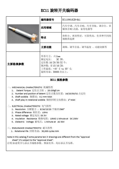
EC11旋转开关编码器编码器型号EC110901K2B-HA1应用领域汽车空调、汽车音响,汽车导航、调音台、多媒体音响\功放,家用电器等特点体积小,密封性好,可靠性高,有多种不同的规格供选择主要功能调频、调节音量、调节温度、功能切换等主要格规参数外形尺寸:∮11mm额定电压:DC5V;定位数:16/20/30/32个;脉冲数:8/15/16/20;工作温度:-40°C to85°C;旋转寿命:30000次以上;EC11规格参数一、MECHANICAL CHARACTERISTIC机械特性1、Detent Torque定位点力矩:20-200gf.cm2、Number and position of detent定位点数及位置:16/20/30/32点定位3、Shaft wobble轴摆动:0.2mm MAX4、Shaft play in rotational wobble轴的回转方向摆动:2°MAX二、ELECTRICAL CHARACTERISTIC电气特性1、Resolution分解能力:8/16/15/20个脉冲/360°2、Phase difference相位差:≥3ms3、Rated voltage额定电压:DC5V4、Insulation Resistance绝缘电阻:10MΩ1Minute at DC250V5、Dielectric Voltage耐电压:1Minute at AC50V三、ENDURANCE CHARACTERISTIC耐久特性1、Rotational life回转寿命:30,000cycles MinNote:In this catalog,if some parame ters lr drawings are different from the"Approval sheet",it's subject to the"Approval sheet".注明:如说明书与承认书规格参数、图面有异,均以承认书为准。
ATM60-90系列绝对值旋转编码器选型手册(中文版)

1030006 1030007 1030008
动
角度分辨率
0.043°
控
测量误差 重复精度
± 0.25° 0.1°
制
输出接口
SSI,RS422
传
输出码
格雷 码/二 进 制码
感
编码方向
顺时 针/逆 时 针
器
定位时间
0.15ms
接口信号 Clock+,Clock-,Data+,Data-8)
用 于SSI通 讯 模 式 : 最 大 时钟
频 率1MHz; 也 就 是 说 , 时 钟
分ቤተ መጻሕፍቲ ባይዱ率 高达26位
多圈绝对型旋转编码器
ATM60/ATM90: 多圈绝对型旋转编码器 结构坚固,性能可靠
多种接线方式: 插头式,接线端子式
多种输出接口: SSI,Profibus,CANopen和 DeviceNet等;可以满足不 同应用场合的需求。
旋转编码器提供了SSI输出接口 或者RS422参数配置接口也可作为 标准输出接口,并提供连接到
1)在这种 情 况下,用 户将轴封去掉 2)参照DIN IEC 68,2-27部 分 3)参照DIN IEC 68,2-6部分 4)在编 码 器 上 无密封 圈 5)在编 码 器 上 有密封 圈
订货资料
ATM60夹 紧 法 兰 ; 6mm轴 径 ; 电 源 电 压US 10...32V;SSI输 出 接 口/ RS422输出 接 口 1 出 厂 设 置 :4,096脉 冲/圈x 4,096圈 , 格 雷 码 , 电 调 节 信 号"Set”=0
596 运动控制传感器
1 R=最 小 弯 曲 半 径40mm
针脚号
1 2 3 4 5 6 7 8 9 10 11 12
AUTONICS 光电传感器 BUP SERIES 说明书
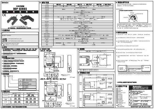
使用环境温度 使用环境湿度 保护结构 材质 配线事项 附件 重量 重量是包装盒除外的重量.
的情况
保存时
警告 注意
如果不按照说明操作会发生意外. 如果不按照说明操作会导致产品损坏.
规格
规格 外壳 : ABS, 盖子
长度 调节起子 约90g 约140g 调节起子
产品和使用说明书中的符号如下表示. 在特殊情况下会出现意外或危险.
各方向2小时 各方向3次 以下 收光面照度 未结冰状态 规格 保存时 规格
以下 和
白炽灯
使用注意事项
避免强光光源(太阳光,聚光灯等)直接照射,可使用遮光板,保护套等处理. 光电传感器在荧光灯下使用可能引起误动作,应使用遮光板隔离. 光电传感器的配线与高压线,动力线一起铺管时,可能因此发生误动作或引起 故障,须另外布线或单独铺管使用.
警告
以下情况使用这个设备时,如(核能控制,医疗设备,汽车,火车,飞机,航空, 娱乐或安全装置等).需要安装安全保护装置,或联系我们索取这方面的资料. 否则会引起严重的损失,火灾或人身伤害. 不要随意拆卸和改动这个产品,如确实需要请联系我们. 否则会引起触电和火灾.
本产品使用在尘埃大或腐蚀性场所可能引起误动作.
遮光动作
注)控制输出端子电流在额定保护电流以上时,保护电路动作,控制信号不输出.
本说明书的记载事项,外型尺寸图如有改善恕不另行通知.
单位
NO20070925-EP-CE-08-0120E
�
〈BUP-30S,BUP-50S,BUP-50S-P〉
检测范围 最佳检测位置
非常感谢您选择AUTONICS的产品 为了您的安全,请在使用前阅读以下的内容
注意安全
在使用前请认真阅读说明书 请遵守下面的要点
CT6 计数器说明书

计数值
计数输入 计数命令输入
当
是 计数
当
是
计数
(加/减-C) 相位差输入
计数值
计数 计数
输出 输出
当
和
应用
将保留先前的计数值.
当使用编码器的A,B相位输出到
输入, 请设置计数器的相位差模式
记号
输入类型
电压输入
连接输入 短路 开路
的计数动作 显示专用
向上计数输入模式
向下计数输入模式
命令输入模式 相位差输入
出为ON和计数值将复位的 同一时间计数再次动作.
OUT2的
时间过后
OUT1的维持输出关掉 ,
的 输出
与
的动作无关.
UP计数后,这个显示值增加
或减少由OUT2的.
时间决定, OUT2的
时间过后
OUT1的维持输出关掉 ,
的 输出
与
的动作无关.
显示值和OUT1的保持输出是
维持到复位信号来.
的 输出
与
的动作无关.
要按 两次。
改变 到 按
设定
时间,按
自动模式。
第一个数位闪烁。
两次 进入
随时按 键,改变预设时间的状态。 切换闪烁的位数是从右到左。
切换闪烁的数位到 的位置可按 2次。
使用
时 ,不能使用双预设。
改变
到
按
2次,完成预设值的设置和 返回到运行模式请按 键。
计数和
计数的动作
预设值
复位 预设值
输出
计数动作
计数值是增量的,当
清洁这个产品时,不要使用水或油性清洁剂.
否则会发生触电或火灾,也将损坏本产品.
在易燃易爆,潮湿,太阳光直射,热辐射,振动等场所应避免使用这个单元.
Autonics 电感型接近开关 说明书
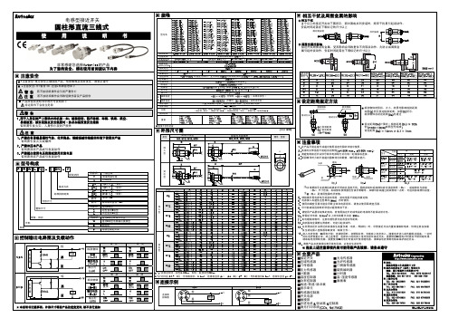
规格
型号名
检测距离 应差距离 标准检测物 设定距离 电源电压
使用电压范围
消耗电流 响应频率 残留电压 温度影响 控制输出 绝缘阻抗
耐电压 耐振动 抗冲击 指示灯
PR08-1.5DN PR08-1.5DP PR08-1.5DN2 PR08-1.5DP2 PRL08-1.5DN PRL08-1.5DP PRL08-1.5DN2 PRL08-1.5DP2 PRW08-1.5DN PRW08-1.5DP PRW08-1.5DN2 PRW08-1.5DP2 PRW08-1.5DN-V PRW08-1.5DP-V PRWL08-1.5DN PRWL08-1.5DP PRWL08-1.5DN2 PRWL08-1.5DP2
PR18-8DN PR18-8DP PR18-8DN2 PR18-8DP2 PRL18-8DN PRL18-8DP PRL18-8DN2 PRL18-8DP2 PRW18-8DN PRW18-8DP PRW18-8DN2 PRW18-8DP2 PRWL18-8DN PRWL18-8DP PRWL18-8DN2 PRWL18-8DP2
-
5
35
42
2,000
-
5
35
42
300
44
5
35
42
300
44
5
35
42
5,3芯(导体截面积0.3mm ,绝缘体直径 1.25)
连接示例
连接器 接线图
21 34
NPN
棕
黑 蓝
+V 负载
0V
PNP
21 棕 34 黑
蓝
+V
负载 0V
相互干扰及周围金属的影响
个以上的接近开关如下图所示,面对面或并列安装时,频率干扰易引起误动作, 安装时间距需在下表标记的尺寸以上
autonics旋转编码器中文选型手册及说明书
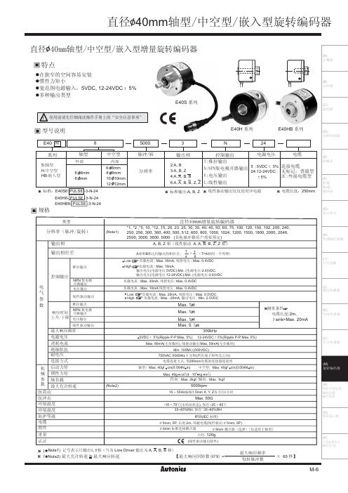
>4@PUT B ?4@PUT B N4@PUT C D4@PUT C c4@PUT Z C4@PUT Z F4@1V.;VED O;,/ c4@HOE.6V/ yQ@GM H
Nb@f OQO JuI\m@f ul@f
\g.w@f
/; @f m4 /;
Q
PUT B >4 Q
B
PUT C N4 B
C PUT Z c4 C
B2 C2 Z ]J\g.w B2 B2 C2 C2 Z2 Z ]K
.Ogk^8/
Mgn Ib`a
B]<C]4O@fq]S`L
T :
OT >
JTAB]qp1<{K
,*ul @ N[o4 96eB2 [kul @ N[o4 64:VED
,*ul @ N[o4 76eB2 @ful.uzul ;VED/@Nbf4 .uzul3846/VED2 @ful.uzul 7838:VED/@Nbf4 .uzul3946/VED
376 q =6?.RSVBG/2 Pi@38; q >;? 9;q>;,RI2 Pi@ 9;q?6,RI
JQ;6.JFD TC/
@;ee2 ;Q2 by@8e2 yQud.\g.w@@;ee2 >Q/
@<ee TChRK=~
@>ee K=~Jk,K6T>uw=e7
k|4 786`
.\g.w@fgO/
=;6VBD ;65<6Ip 7 *9.EvzE<O^4O/ udhR}:2 l866eeudqhR~hRe
=eLN[o4 :6`_ \e.6466:O e/ 8_eLN[o4 :6`_ \e.6466:O e/ N[o4 :6` \e8 .: =763< c` e8/ X` @ N[o4 8c`_2 =` @ N[o4 7c`_ ;666ihe 76 q ;;Ip1+74;ee X2 Y2 Z2}`|b8 N[o4 ;6H
IXARC绝对旋转编码器说明书.pdf_1730164991.9233062

Data SheetIXARC Absolute Rotary EncoderOCD-D2C1B-1216-S06V-H3PInterface Interface DeviceNetProfileCIP (Common Industrial Protocol)Manual Functions Address selector switch 0-99 and terminal resistor (with connection cap)Transmission Rate 150 kBaud, 250 kBaud, 500 kBaud Interface Cycle Time ≥ 10 msProgramming FunctionsResolution, preset, complement, transmission mode: polled mode, cyclic mode, sync modeOutputs Output DriverTransceiver (ISO 11898), Galvanically Isolated by Opto-CouplersElectrical Data Supply Voltage 10 – 30 VDCCurrent Consumption ≤ 230 mA @ 10 V DC, ≤ 100 mA @ 24 V DC Power Consumption ≤ 2.5 W Start-Up Time< 1 s Reverse Polarity Protection Yes Short Circuit Protection YesEMC: Emitted Interference DIN EN 61000-6-4EMC: Noise ImmunityDIN EN 61000-6-2Data SheetMTTF 13.5 years @ 40 °CSensor TechnologyOptical Resolution Singleturn 16 bit Resolution Multiturn 12 bitMultiturn Technology Mechanical Gearing (no Battery)Accuracy (INL)±0.0220° (14 – 16 bit), ±0.0439° (≤13 bit)CodeBinaryEnvironmental Specifications Protection Class (Shaft)IP66/IP67Protection Class (Housing)IP68/IP69K Operating Temperature - +85 °C (+185 °F)Storage Temperature -40 °C (-40 °F) – +85 °C (+185 °F)Humidity98% RH, no condensationMechanical Data Connection Cap Material Stainless Steel V2A (1.4305; 303)Housing Material Stainless Steel V2A (1.4305, 303)Housing Coating No CoatingFlange Type Synchro, ø 58 mm (S)Flange Material Stainless steel V2A (1.4305; 303)Shaft Type Solid, Length = 10 mm Shaft Diameter ø 6 mm (0.24")Shaft Material Stainless Steel V2A (1.4305, 303)Max. Shaft LoadAxial 40 N, Radial 110 N Minimum Mechanical Lifetime (10^8 revolutions with Fa/Fr)400 (20 N / 40 N)Rotor Inertia ≤ 30 gcm² [≤ 0.17 oz-in²]Friction Torque≤ 5 Ncm @ 20 °C, (7.1 oz-in @ 68 °F)Max. Permissible Mechanical Speed ≤ 3000 1/minShock Resistance≤ 100 g (half sine 6 ms, EN 60068-2-27)Permanent Shock Resistance ≤ 10 g (half sine 16 ms, EN 60068-2-29)Vibration Resistance ≤ 10 g (10 Hz – 1000 Hz, EN 60068-2-6)Length 85,5 mm (3.37")Weight1005 g (2.22 lb)Data SheetElectrical Connection Connection Orientation RadialConnection Type 3 x Cable GlandProduct Life Cycle Product Life Cycle Established ApprovalCE Connection Plan SIGNAL PIN NUMBER Power Supply +GND -CAN High H CAN Low L CAN GND G CAN High H CAN Low L CAN GND G GND┴Connector-View on Encoder Dimensional Drawing 2D DrawingData SheetAccessoriesCouplingsCoupling Bellow Type-06-06Coupling Bellow Type-06-10Coupling Bellow Type-06-08Coupling Bellow Type-06-(3/8")Coupling Bellow Type-06-(1/4")Coupling Jaw Type-06-06Coupling Jaw Type-06-10Coupling Jaw Type-06-08Coupling Jaw Type-06-12Coupling Jaw Type-06-(1/4")Coupling Jaw Type-06-(3/8")Coupling Disc Type-06-06Coupling Disc Type-06-10MoreAdapter FlangesMounting Bracket for Synchro Flange w/ fixtures Clamping RingsClamp Disc w/ Eccentric Hole-4pcs Clamp Disc w/ Centred Hole-4pcsContactContact UsThe picture and drawing are for general presentation purposes only. Please refer to the "Download" section for detailed technical drawings.All dimension in [inch] mm. © FRABA B.V., All rights reserved. We do not assume responsibility for technical inaccuracies or omissions.Specifications are subject to change without notice.。
IXARC绝对旋转编码器说明书.pdf_1730845740.1955516
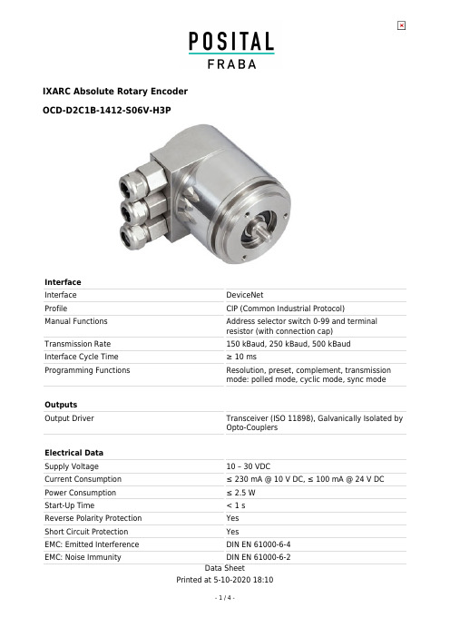
Data SheetIXARC Absolute Rotary EncoderOCD-D2C1B-1412-S06V-H3PInterface Interface DeviceNetProfileCIP (Common Industrial Protocol)Manual Functions Address selector switch 0-99 and terminal resistor (with connection cap)Transmission Rate 150 kBaud, 250 kBaud, 500 kBaud Interface Cycle Time ≥ 10 msProgramming FunctionsResolution, preset, complement, transmission mode: polled mode, cyclic mode, sync modeOutputs Output DriverTransceiver (ISO 11898), Galvanically Isolated by Opto-CouplersElectrical Data Supply Voltage 10 – 30 VDCCurrent Consumption ≤ 230 mA @ 10 V DC, ≤ 100 mA @ 24 V DC Power Consumption ≤ 2.5 W Start-Up Time< 1 s Reverse Polarity Protection Yes Short Circuit Protection YesEMC: Emitted Interference DIN EN 61000-6-4EMC: Noise ImmunityDIN EN 61000-6-2Data SheetMTTF 13.5 years @ 40 °CSensor TechnologyOptical Resolution Singleturn 12 bit Resolution Multiturn 14 bitMultiturn Technology Mechanical Gearing (no Battery)Accuracy (INL)±0.0220° (14 – 16 bit), ±0.0439° (≤13 bit)CodeBinaryEnvironmental Specifications Protection Class (Shaft)IP66/IP67Protection Class (Housing)IP68/IP69K Operating Temperature - +85 °C (+185 °F)Storage Temperature -40 °C (-40 °F) – +85 °C (+185 °F)Humidity98% RH, no condensationMechanical Data Connection Cap Material Stainless Steel V2A (1.4305; 303)Housing Material Stainless Steel V2A (1.4305, 303)Housing Coating No CoatingFlange Type Synchro, ø 58 mm (S)Flange Material Stainless steel V2A (1.4305; 303)Shaft Type Solid, Length = 10 mm Shaft Diameter ø 6 mm (0.24")Shaft Material Stainless Steel V2A (1.4305, 303)Max. Shaft LoadAxial 40 N, Radial 110 N Minimum Mechanical Lifetime (10^8 revolutions with Fa/Fr)400 (20 N / 40 N)Rotor Inertia ≤ 30 gcm² [≤ 0.17 oz-in²]Friction Torque≤ 5 Ncm @ 20 °C, (7.1 oz-in @ 68 °F)Max. Permissible Mechanical Speed ≤ 3000 1/minShock Resistance≤ 100 g (half sine 6 ms, EN 60068-2-27)Permanent Shock Resistance ≤ 10 g (half sine 16 ms, EN 60068-2-29)Vibration Resistance ≤ 10 g (10 Hz – 1000 Hz, EN 60068-2-6)Length 85,5 mm (3.37")Weight1005 g (2.22 lb)Data SheetElectrical Connection Connection Orientation RadialConnection Type 3 x Cable GlandProduct Life Cycle Product Life Cycle Established ApprovalCE Connection Plan SIGNAL PIN NUMBER Power Supply +GND -CAN High H CAN Low L CAN GND G CAN High H CAN Low L CAN GND G GND┴Connector-View on Encoder Dimensional Drawing 2D DrawingData SheetAccessoriesCouplingsCoupling Bellow Type-06-06Coupling Bellow Type-06-10Coupling Bellow Type-06-08Coupling Bellow Type-06-(3/8")Coupling Bellow Type-06-(1/4")Coupling Jaw Type-06-06Coupling Jaw Type-06-10Coupling Jaw Type-06-08Coupling Jaw Type-06-12Coupling Jaw Type-06-(1/4")Coupling Jaw Type-06-(3/8")Coupling Disc Type-06-06Coupling Disc Type-06-10MoreAdapter FlangesMounting Bracket for Synchro Flange w/ fixtures Clamping RingsClamp Disc w/ Eccentric Hole-4pcs Clamp Disc w/ Centred Hole-4pcsContactContact UsThe picture and drawing are for general presentation purposes only. Please refer to the "Download" section for detailed technical drawings.All dimension in [inch] mm. © FRABA B.V., All rights reserved. We do not assume responsibility for technical inaccuracies or omissions.Specifications are subject to change without notice.。
IXARC绝对旋转编码器数据手册说明书
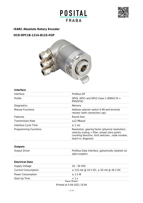
Data SheetIXARC Absolute Rotary EncoderOCD-DPC1B-1216-B12S-H3PInterface Interface Profibus DPProfile DPV0, DPV1 and DPV2 Class 2 (EN50170 +EN50254)Diagnostics MemoryManual Functions Address selector switch 0-99 and terminal resistor (with connection cap)FeaturesRound Axis Transmission Rate ≤12 Mbaud Interface Cycle Time ≥ 1 msProgramming FunctionsResolution, gearing factor (physical resolution) ,velocity scaling + filter, preset (zero point),counting direction, limit switches , node number,teach-in, diagnosisOutputs Output DriverProfibus Data Interface, galvanically isolated via opto-couplersElectrical Data Supply Voltage 10 – 30 VDCCurrent Consumption ≤ 115 mA @ 10 V DC, ≤ 50 mA @ 30 V DC Power Consumption ≤ 1.5 WStart-Up Time< 1 sData SheetReverse Polarity Protection Yes Short Circuit Protection YesEMC: Emitted Interference DIN EN 61000-6-4EMC: Noise Immunity DIN EN 61000-6-2MTTF 13.5 years @ 40 °CSensor TechnologyOptical Resolution Singleturn 16 bit Resolution Multiturn 12 bitMultiturn Technology Mechanical Gearing (no Battery)Accuracy (INL)±0.0220° (14 – 16 bit), ±0.0439° (≤13 bit)CodeBinaryEnvironmental Specifications Protection Class (Shaft)IP66/IP67Protection Class (Housing)IP66/IP67Operating Temperature -40 °C (-40 °F) - +85 °C (+185 °F)Storage Temperature -40 °C (-40 °F) – +85 °C (+185 °F)Humidity98% RH, no condensationMechanical Data Connection Cap Material Aluminum Housing Material SteelHousing CoatingWet coating (RAL 9006 White Aluminium) +Cathodic corrosion protection (>720 h salt spay resistance)Flange Type Blind Hollow, ø 58 mm (B)Flange Material AluminumShaft Type Blind Hollow, Depth = 30 mm Shaft Diameter ø 12 mm (0.47")Shaft Material Stainless Steel V2A (1.4305, 303)Rotor Inertia ≤ 30 gcm² [≤ 0.17 oz-in²]Friction Torque≤ 5 Ncm @ 20 °C, (7.1 oz-in @ 68 °F)Max. Permissible Mechanical Speed ≤ 3000 1/minShock Resistance≤ 100 g (half sine 6 ms, EN 60068-2-27)Permanent Shock Resistance≤ 10 g (half sine 16 ms, EN 60068-2-29)Data SheetVibration Resistance ≤ 10 g (10 Hz – 1000 Hz, EN 60068-2-6)Length 99 mm (3.90")Weight485 g (1.07 lb)Maximum Axial / Radial MisalignmentStatic ± 0.3 mm /± 0.5 mm; Dynamic ± 0.1 mm /± 0.2 mmElectrical Connection Connection Orientation RadialConnection Type 3 x Cable GlandConnection Cap TypeRemovable for easy replacing encoder without new installation of cable, Rotary switches with visible node number, No active components,Terminal resistor switch cut the outgoing bus too,Big spring clipsProduct Life Cycle Product Life Cycle Established ApprovalCEConnection Plan SIGNALPIN NUMBER Bus line B (Bus in)B Bus line A (Bus in)A GND−Power Supply +Bus line B (Bus out)BBus line A (Bus out)AData SheetGND−Power Supply+Connector-View on Encoder Dimensional Drawing 2D DrawingAccessoriesClamping Rings Clamping Ring B15Got questions? Need an individual solution? We are here to help!Contact UsThe picture and drawing are for general presentation purposes only. Please refer to the "Download" section for detailed technical drawings.All dimension in [inch] mm. © FRABA B.V., All rights reserved. We do not assume responsibility for technical inaccuracies or omissions.Specifications are subject to change without notice.。
IXARC绝对旋转编码器说明书.pdf_1730864893.3108768
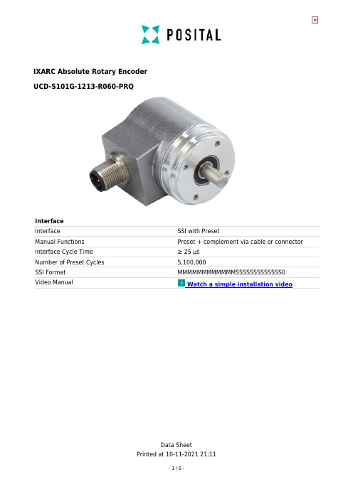
Data SheetIXARC Absolute Rotary EncoderUCD-S101G-1213-R060-PRQInterface Interface SSI with PresetManual Functions Preset + complement via cable or connector Interface Cycle Time ≥ 25 µs Number of Preset Cycles 5,100,000SSI Format MMMMMMMMMMMMSSSSSSSSSSSSS0Video ManualWatch a simple installation videoData SheetOutputs Output Driver RS422Electrical Data Supply Voltage 4.5 – 30 VDC Current Consumption Typical 50 mA Power Consumption ≤ 1.0 W Start-Up Time < 1 sClock Input RS 422, via Optocoupler Clock Frequency100 kHz – 2 MHz Reverse Polarity Protection Yes Short Circuit ProtectionYesData SheetEMC: Emitted Interference DIN EN 61000-6-4EMC: Noise Immunity DIN EN 61000-6-2MTTF 350 years @ 40 °CSensor TechnologyMagnetic Resolution Singleturn 13 bit Resolution Multiturn 12 bitMultiturn Technology Self powered magnetic pulse counter (no battery,no gear)Accuracy (INL)±0.0878° (≤ 12 bit)Sense Signal (Default)Clockwise shaft movement (front view on shaft)CodeGrayEnvironmental Specifications Protection Class (Shaft)IP65Protection Class (Housing)IP65Operating Temperature -40 °C (-40 °F) - +85 °C (+185 °F)Humidity98% RH, no condensationMechanical Data Housing Material SteelHousing Coating Cathodic corrosion protection (>720 hrs salt spray resistance)Flange Type Synchro, ø 36 mm Flange Material AluminumShaft Type Solid, Length = 11.5 mm Shaft Diameter ø 6 mm (0.24")Shaft Material Stainless Steel V2A (1.4305, 303)Max. Shaft LoadAxial 40 N, Radial 110 NMinimum Mechanical Lifetime (10^8 revolutions with Fa/Fr)40 (20 N / 40 N), 14 (40 N / 60 N), 10 (40 N / 80N), 6 (40 N / 110 N)Friction Torque≤ 3 Ncm @ 20 °C (4.2 oz-in @ 68 °F)Max. Permissible Mechanical Speed ≤ 12000 1/minShock Resistance≤ 100 g (half sine 6 ms, EN 60068-2-27)Permanent Shock Resistance ≤ 10 g (half sine 16 ms, EN 60068-2-29)Vibration Resistance ≤ 10 g (10 Hz – 1000 Hz, EN 60068-2-6)Length39 mm (1.54")Data SheetWeight140 g (0.31 lb)Electrical Connection Connection Orientation RadialConnectorM12, Male, 8 pin, a codedProduct Life Cycle Product Life Cycle Established ApprovalCE + cULusConnection Plan SIGNAL PIN NUMBER Power Supply 2GND 1Data+5Data-6Clock+3Clock-4Preset 7DIR 8ShieldingConnector HousingConnector-View on EncoderRotation Clockwise (seen on shaft)Dimensional DrawingData Sheet2D DrawingAccessoriesConnectors & Cables10m PUR Cable, 8pin, A-Coded, fPOS M12 8pin-A Female+5m PUR Cable POS M12 8pin-A Female+2m PUR Cable POS M12 8pin-A Female+10m PUR Cable M12, 8pin A-Coded, Female MoreCouplingsCoupling Bellow Type-06-06Coupling Bellow Type-06-10Coupling Bellow Type-06-(3/8")Coupling Bellow Type-06-(1/4")Coupling Jaw Type-06-06Coupling Jaw Type-06-10Coupling Jaw Type-06-08Coupling Jaw Type-06-12Coupling Jaw Type-06-(1/4")Coupling Jaw Type-06-(3/8")Coupling Disc Type-06-06Coupling Disc Type-06-10MoreAdapter FlangesSpring Loaded Pivot Arm 36mm Clamping RingsClamp Disc w/ Eccentric Hole-4pcs Clamp Disc w/ Centred Hole-4pcs DisplaysAP21-00 SSI DisplayAP21-DA SSI Display (4 dig. + analog o/p)DiMod-P SSI DisplayConfiguration/Programming Tools SSI2USB Adapter DB15 (VA01)Got questions? Need an individual solution? We are here to help!Data SheetContact UsThe picture and drawing are for general presentation purposes only. Please refer to the "Download" section for detailed technical drawings.All dimension in [inch] mm. © FRABA B.V., All rights reserved. We do not assume responsibility for technical inaccuracies or omissions.Specifications are subject to change without notice.。
AS5134 磁性旋转编码器操作手册说明书

1 General OverviewThe AS5134 is a contactless magnetic rotary encoder for accurate angular measurement over a full turn of360º. It is a system-on-chip, combining integrated Hall elements, analog front end and digital signal processing in a single device.To measure the angle, only a simple two-pole magnet, rotating over the center of the chip is required. The absolute angle measurement provides instant indication of the magnet’s angular position with aresolution of 8.5 bit = 360 positions per revolution. This digital data is available as a serial bit stream and as a PWM signal.In addition to the angle information, the strength of the magnetic field is also available as a 6-bit code. Data transmission can be configured for 1-wire (PWM), 2-wires (DCLK, DIO) or 3-wires (DCLK, DIO, CS).A software programmable (OTP) zero position simplifies assembly as the zero position of the magnet does not need to be mechanically aligned.A Power Down Mode together with fast startup and measurement cycles allows for very low average power consumption.2 The AS5134 DemoboardThe AS5134 demoboard is a complete rotary encoder system with built-in microcontroller, USB interface, graphical LCD display, incremental indicators, commutation indicators and PWM output LED.The board is USB powered or externally supplied with a 9V battery for standalone operation.Note: Switch INT – EXT will be available in version AS5134-DB-v1.4. One can chose between the internal and an external device.3 Operating the AS5134 DemoboardThe AS5134 demoboard can be used in several ways:• As standalone unit supplied by a 9V batteryConnect a 9V battery to the battery connector on the top right side of the board. No other connections are required.AS51348 BIT PROGRAMMABLE HIGH SPEED MAGNETIC ROTARY ENCODERAS5134-DB-1.3 Demoboard OPERATION MANUALLCD display (for standalone mode)9V battery connector (standalone only)• As standalone unit supplied by an USB portConnect the demoboard to a PC using a USB/USB cable (included in demoboard shipment). The board is supplied by the 5V supply of the USB port. No other connections are required.• As input device for the AS5000 Programmer GUI softwareThis configuration uses the same USB hardware connection as above, but additionally the AS5000 Programmer GUI software is running. The LCD display will be turned off and the Angle/Multiturn/AGC will be displayed on the PC screen. Some extra features as pole pair, zero position or AGC programming can be achieved. The parameters will not be permanently programmed. All the parameters will be lost when the demoboard is shut down. For a permanent device programming, the “AS5000 Programmer” hardware should be used.3.1 Hardware Indicators3.1.1Graphic LCD displayThe LCD display shows the realtime absolute angle position of the magnet as a 8.5bit digital word (0…360). Turning the knob clockwise will increase the angle value until 359, then 0.The Multiturn counter register will increment at each 359° 0° transition, and will decrease at each 0° 359° transition (counter clockwise). The Multiturn (MTURN) value is continuously read from the AS5134 Multiturn register. The AGC value is continuously updated as well.The magnet status indicator depends on the AGC value. If AGC = 0, the magnet it too close to the encoder, and“Magnet too close” will be displayed. If AGC = 63, the magnet is too far away from the encoder (maximum AGC value), and “Magnet too far” will be displayed.3.1.2PWM LEDThis LED is connected to the PWM output of the AS5134. The PWM output is a pulse width that is proportional to the angle of the magnet.The pulse width varies from 16µs to 734µs with a repetition rate of 1.33 kHz. Viewing the PWM signal on the LEDresults in a brightness that is proportional to the angle of the magnet. When the angle of the magnet is at 0°, the LED is almost dark, as it is 16µs on and 734µs off. Turning the knob clockwise towards higher angles increases the brightness of the PWM LED, since the ON-pulse becomes longer and the OFF-pulse becomes shorter.Likewise, the PWM output can be used as an analog output proportional to the angle, when the PWM signal is filtered by a RC (or active) lowpass filter.The PWM signal (0-5V) can be directly taken from the connector J4. 3.1.3UVW commutation LEDThe UVW commutation signals are used to control the electrical angle information of a BLDC motor (see AS5134 Datasheet Figure 10).The UVW LEDs are directly connected to the U V W outputs of the AS5134. These UVW signals (0-5V) are available on connector J7. 3.1.4Incremental quadrature AB-Index LEDThe phase shift between channel A and B indicates the direction of the magnet movement. Channel A leads channel B at a clockwise rotation of the magnet (top view) by 90 electrical degrees. Channel B leads channel A at a counter clockwise rotation. One Index pulse (5V) is generated at the angle 0 (see AS5134 datasheet Figure 9)The AB-Index LEDs are directly connected to the A B Index outputs of the AS5134. These quadrature signals (0-5V) are available on connector J7.4AS5000 Programmer GUI software4.1Installing the GUI on the PCThe preliminary software is developed for a Microsoft Windows XP operating system with Service Pack 2. In additionthe dotnet (.NET) framework version 2.0 or more must be installed on the PC. This package can be downloaded free of charge from the Microsoft webpage:/downloads/details.aspx?FamilyID=0856eacb-4362-4b0d-8edd-aab15c5e04f5&displaylang=en Following Procedure is recommended before starting the GUI:1.check on your PC if Service Pack 2 is installed2.install the mentioned .NET package to your computer3.execute setup.exe4.Finally start the GUI using the shortcut in the start menu or desktop.4.2The Home tabFigure 3 shows the main window of the GUI. On the top left corner, board informations as firmware (FW) version and demoboard name declaration can be found.By default the GUI is in the auto detection mode. Any connected austriamicrosystems demoboard and programming tool will be automatically detected and displayed in the right top corner. The GUI is divided into three main sections HOME, TWI and OTP.By selecting the TWI (AS5134 bidirectional serial protocol) tab, the information of the angular position and the status bits appears. See figure 4.Figure 3: AS5000 GUI detected the AS5134 Demoboard4.3 The TWI tabThis mode displays in realtime the angle value, Multiturn register value, AGC value and the UVW signal status.Figure 4: TWI tab, allows access to the AS5134 registers from the serial busValue is the Angle[8:0] from the RD_ANGLE (Read Angle) serial command. This value is continuously updated.The Zero Position value represents the Zero Position register. By clicking on the Set button, the actual angle “Value” is written into the Zero Position register. Clicking on Reset writes the value 0 to the Zero Position register.The Multiturn Counter field is the Multiturn-counter[8:0] register value from the READ_MT_COUNTER serial command. The Multiturn counter register can be set to a specific value by entering the turn number and clicking on Set. The counter can be reseted to 0 (default value) by clicking on ResetThe AGC value is continuously read from the RD_ANGLE serial command.The range lamp can be set by two thresholds (Green Orange and Orange Red) which are determined by the user. Those thresholds have no influence on the AS5134, it is a visual representation only. The Read Interval can be modified from 10 ms (fastest) to 1 s (slowest).The BLDC Commuting Signals sub-window is a realtime representation of the commutation signal status on the AS5134 UVW outputs. For changing the number of pole pairs, see chapter Error! Reference source not found.. By clicking on Digital Interface, a new window opens, and allows the user to write directly into the AS5134registers. See chapter 4.4.Realtime UVW signal representation4.4Digital Interface sub-windowFigure 5: TWI interface sub-windowThe Digital interface window allows accessing the internal registers of the AS5134:The parameters don’t need to be checked manually in the “Bits” window on the right, but can be set by the “Fields” and “Options for the selected bits” values. The corresponding bits will be checked automatically.To validate the command, the Execute Write button bust be clicked.4.5OTP tabThe OTP tab is normally used for the AS5000 programmer, but the OTP bits can be changed on the AS5134 demoboard as well.Options like sensitivity, incremental output mode, UVW output mode can be changed by selecting the function in “Fields”, then changing the parameter in “Options for the selected field” or directly the decimal value of this parameter in “Value”. Each time a field’s value has been changed, the corresponding OTP bits will be automatically checked in the right window. The button Write should be clicked to write the parameter into the AS5134.The Read button reads back the OTP register, and updates the “Field” parameter as well as the OTP bits window.Figure 6: OTP tabField Sensitivity: Sets the gain of the internal signal path.-0: Sensitivity = 1.65-1: Sensitivity = 1.88-2: Sensitivity = 2.11-3: Sensitivity = 2.35Field ABI: To change the Incremental AB-Index output to:-0: Quadrature (default)-1: Step/Direction (A = Step, B = Direction)-2: Pulse/Direction (A = 1us pulse, B = Direction)-3: Output OFFField UVW: To change the BLDC pole pairs. The result can be checked in realtime in the BLDC window.-0: Sensitivity = 1 pole pair-1: Sensitivity = 2 pole pair-2: Sensitivity = 3 pole pair-3: Sensitivity = 4 pole pair-4: Sensitivity = 5 pole pair-5: Sensitivity = 6 pole pair-6: Sensitivity = 10 pole pair-7: Sensitivity = output OFFField Zero Position: To zero position value, like on the TWI tab. The zero position value can be changed by checking the Z[0:8] bits, or changing the Value field with a decimal number.Note that the Zap! button is used for the AS5000 Programmer only and has no effect on the AS5134 Demoboard.5AS5134 Demoboard SchematicsFigure 7: AS5134 Demoboard schematicsIndex1General Overview (1)2The AS5134 Demoboard (1)3Operating the AS5134 Demoboard (1)3.1Hardware Indicators (2)3.1.1Graphic LCD display (2)3.1.2PWM LED (2)3.1.3UVW commutation LED (2)3.1.4Incremental quadrature AB-Index LED (2)4AS5000 Programmer GUI software (3)4.1Installing the GUI on the PC (3)4.2The Home tab (3)4.3The TWI tab (4)4.4Digital Interface sub-window (5)4.5OTP tab (6)5AS5134 Demoboard Schematics (7)Index (8)Revision History (9)Contact (10)Copyright (11)1.0 January 29, 2009First version1.1 October 07, 2009 Update of Fig.1; new formattingContactHeadquarters austriamicrosystems AGA 8141 Schloss Premstätten, Austria Phone: +43 3136 500 0Fax: +43 3136 525 01**************************************** Sales Offices austriamicrosystems Germany GmbH Tegernseer Landstrasse 85D-81539 München, Germany Phone: +49 89 69 36 43 0 Fax: +49 89 69 36 43 66austriamicrosystems Italy S.r.l.Via A. Volta, 18I-20094 Corsico (MI), ItalyPhone: +39 02 4586 4364 Fax: +39 02 4585 773austriamicrosystems France S.A.R.L. 124, Avenue de ParisF-94300 Vincennes, France Phone: +33 1 43 74 00 90 Fax: +33 1 43 74 20 98austriamicrosystems Switzerland AG Rietstrasse 4CH 8640 Rapperswil, Switzerland Phone: +41 55 220 9008Fax: +41 55 220 9001austriamicrosystems UK, Ltd.88, Barkham Ride, Finchampstead, Wokingham Berkshire RG40 4ET, United Kingdom Phone: +44 118 973 1797 Fax: +44 118 973 5117austriamicrosystems AG Klaavuntie 9 G 55FI 00910 Helsinki, FinlandPhone: +358 9 72688 170 Fax: +358 9 72688 171austriamicrosystems AGBivägen 3BS 19163 Sollentuna, Sweden Phone: +46 8 6231 710 austriamicrosystems USA, Inc.8601 Six Forks RoadSuite 400Raleigh, NC 27615, USAPhone: +1 919 676 5292Fax: +1 509 696 2713austriamicrosystems USA, Inc.4030 Moorpark AveSuite 116San Jose, CA 95117, USAPhone: +1 408 345 1790Fax: +1 509 696 2713austriamicrosystems AGSuite 811, Tsimshatsui CentreEast Wing, 66 Mody RoadTsim Sha Tsui East, Kowloon, Hong Kong Phone: +852 2268 6899Fax: +852 2268 6799austriamicrosystems AGAIOS Gotanda Annex 5th Fl., 1-7-11, Higashi-Gotanda, Shinagawa-kuTokyo 141-0022, JapanPhone: +81 3 5792 4975Fax: +81 3 5792 4976austriamicrosystems AG#805, Dong Kyung Bldg.,824-19, Yeok Sam Dong,Kang Nam Gu, SeoulKorea 135-080Phone: +82 2 557 8776Fax: +82 2 569 9823austriamicrosystems AGSingapore Representative Office83 Clemenceau Avenue, #02-01 UE Square 239920, SingaporePhone: +65 68 30 83 05Fax: +65 62 34 31 20AS5134 Demoboard OPERATIONAL MANUALRevision 1.0, 29-Jan-2009 Page 11 of 11CopyrightDevices sold by austriamicrosystems are covered by the warranty and patent indemnification provisions appearing in its Term of Sale. austriamicrosystems makes no warranty, express, statutory, implied, or by description regarding the information set forth herein or regarding the freedom of the described devices from patent infringement. austriamicrosystems reserves the right to change specifications and prices at any time and without notice. Therefore, prior to designing this product into a system, it is necessary to check with austriamicrosystems for current information. This product is intended for use in normal commercial applications.Copyright © 2009 austriamicrosystems. Trademarks registered ®. All rights reserved. The material herein may not be reproduced, adapted, merged, translated, stored, or used without the prior written consent of the copyright owner. To the best of its knowledge, austriamicrosystems asserts that the information contained in this publication is accurate and correct. However, austriamicrosystems shall not be liable to recipient or any third party for any damages, including but not limited to personal injury, property damage, loss of profits, loss of use, interruption of business or indirect, special, incidental or consequential damages, of any kind, in connection with or arising out of the furnishing, performance or use of the technical data herein. No obligation or liability to recipient or any third party shall arise or flow out of austriamicrosystems rendering of technical or other services.。
- 1、下载文档前请自行甄别文档内容的完整性,平台不提供额外的编辑、内容补充、找答案等附加服务。
- 2、"仅部分预览"的文档,不可在线预览部分如存在完整性等问题,可反馈申请退款(可完整预览的文档不适用该条件!)。
- 3、如文档侵犯您的权益,请联系客服反馈,我们会尽快为您处理(人工客服工作时间:9:00-18:30)。
:;>
M8_e5,3e > 94:
:;>
F:6I
:;>
F:6IC AhRud9/
8;6
N7==7 hRudqkeqZ0w}*oq9/Ct
97
86
7;
76
B
B
4`
<
36467 36467;
>
36467
36468
98
>
BC
@:6
16 86 36468 :6
93786>
.B/
JnS@eeK LA~
. Ogk^7/ M;U;6@f,v-]JoQ Mbf^ Eibm^i @fQ B2 B2 C2 C ]K
. Ogk^8/ Hk~i@D Hk^t@D
;Hk^tE@At320u A
Hk^twn q@peA
= <6 s<
.F/ rOU
.G/ @Dy \D5 peU
.H/ [;ny
.I/ h.~`7~
.J/ \5uz
D
1V
F4 D
HOE
c4 E
G4H
yQ F
G
H
I
G4H.Gb^d] Higlf]/@RpksRs
@f
PUT B PUT B
1V HOE PUT C PUT C PUT Z PUT Z G4H
m4
>4 ?4 F4 c4 N4 D4 c4 C4 yQ
N3=
5X }z88=ey8_ey,3ej@Ro~
dj
.L/ 8uh.~
.M/ lgh.~
.N/ j@Ro~
7>
@7;
@<
1647 6
h=~.F:6S/ M *88 h=~
> 7>
M >ee h=~ 88 84> 7<4; 84>
:3N9=64;
7? 1647 >
6
.O/ ;]XUuH -.w~ -`7~
.P/
8;
Mf[;~
94: 7>48 94:
:3N:=64=
376 q =6?.RSVBG/2 Pi@38; q >;? 9;q>;,RI2 Pi@ 9;q?6,RI
JQ;6.JFD TC/
@;ee2 ;Q2 by@8e2 yQud.\g.w@@;ee2 >Q/
@<ee TChRK=~
@>ee K=~Jk,K6T>uw=e7
k|4 786`
.\g.w@fgO/
udbyL8;6ee
ee *SnJpeyj@K
@f] @f]S`
Nb@f
`7@f
OQO JuI
u
\m@f ul@f
*
Z
\g.w@f
A
Nb@f
^t8O
OQO JuI \m@f
56yYQ ul@f
\g.w@f
Hk^twn uzul a:ul [{G] uul hR}:
H }wgY c 7ggY Z =,* A Hk~i@D
93N9=64; EQ;
Q4D4E96
.C/ L8~
.D/ T`~
8666
TCude ;ee2 ;Q.\g.w@f @ >Q/2
by@86662 yQud
.E/ 3n`7~
.F/ rOU
93786>
93N9=64; EQ;
Q4D4E96
.G/ @Dy \D5 peU
.H/ [;ny
98
>
8=
8666
BC
@:6
B C 4`
<
> 76 78
ห้องสมุดไป่ตู้7;
7=
16467; 36
3N
<6>
96>
R8=
Q4D4E :<
<3@94:
Q4D4E 96
R7?
8:
Q4D4E :< TCude ;ee2 ;Q.\g.w@f @ >Q/2 by@86662 yQud
> kA648
.I/ h.~`7~
.J/ \5uz
.K/ RVh.~
>4@PUT B ?4@PUT B N4@PUT C D4@PUT C c4@PUT Z C4@PUT Z F4@1V.;VED O;,/ c4@HOE.6V/ yQ@GM H
Nb@f OQO JuI\m@f ul@f
\g.w@f
/; @f m4 /;
Q
PUT B >4 Q
B
PUT C N4 B
C PUT Z c4 C
=;6VBD ;65<6Ip 7 *9.EvzE<O^4O/ udhR}:2 l866eeudqhR~hRe
=eLN[o4 :6`_ \e.6466:O e/ 8_eLN[o4 :6`_ \e.6466:O e/ N[o4 :6` \e8 .: =763< c` e8/ X` @ N[o4 8c`_2 =` @ N[o4 7c`_ ;666ihe 76 q ;;Ip1+74;ee X2 Y2 Z2}`|b8 N[o4 ;6H
e;Ct
F:6 I
>
;666
9
F:6I Vj
O
8:
F:6IC Vj
.E/ 3n`7~
Vj
S@=e I@8_e IC@,3e
=e OY
<@ <ee >@ ee
TCLF:6S<wQUMSF 393O38:
F:6I>3 QUMSF 393O38: F:6IC>3 QUMSF 393O38:
9/
8_e
vY
<@ <ee >@ >ee 76@ 76ee 78@ 78ee
pey@ *Sn
@f]
`7@f
uzul
ud
8@B2 C 9@B2 C2 Z :@B2 B2 C2 C
4+Nb@f
1+121JuI\m@f
; @;VEDO ;, 8:@7838:VED
hRud UTMLzLe
5+ul@f
O;,
|.+ORude
<@B2 B2 C2 C2 Z2 Z /+\g@f
TC@f@B2 C2 Z \g.w@fTT9u~5uz
N[o4 7 N[o4 7
N[o4 7 N[o4 6x~
966cIp ;VEDO ;,.Rbhhd^ Q3Q@N[o4 ;,/ 7838:VEDO;,.Rbhhd^ Q3Q@N[o4 ;,/
^iKP udby@8e2 J jbfcAN[o4 86eB
N[o4 >6eB.U,*8/2 \.w@f@N[o4 ;6eB.U,*8/ Nbf4 766NP.;66VED/
@fWf
MNb@fy121JuI\m@fyul@f
B] I
M
I
C]
M
T
T 8
O
T :
T :
O
T >
I
Z] M
DW @+=}`6_
T
O
T 8
DW.B8/}`/
M\g.w@f
B] B]
C] C] Z] Z]
T
T 8
O
T :
T :
O
T >
T
O
T 8
DW.B8/}`/
hR
ATCe
MNb@f 5 OQO JuI\m@f 5 ul@f
6V
OQO JuI\m@f
j@Ro~um
hR
1V
,*
> E
@f
1
m
3
l3ul
@N[o4 96eB
6V
ul@f
j@Ro~um
hR
1V
R
> E m
lful
@N[o4 76eB
@f
1
3 ,*
6V
\g.w@f
j@Ro~um
hR
1V
> E
B ]@f 1
m
3
B ]@f
6V
Nb@f>uw121JuI\m@fJ {KF=ul@fJ |K 0Yq@fum@f]QB2C2Z .\g.w@f B2 B2 C2 C2 Z2 Z/
B2 C2 Z ]J\g.w B2 B2 C2 C2 Z2 Z ]K
.Ogk^8/
Mgn Ib`a
B]<C]4O@fq]S`L
T :
OT >
JTAB]qp1<{K
,*ul @ N[o4 96eB2 [kul @ N[o4 64:VED
,*ul @ N[o4 76eB2 @ful.uzul ;VED/@Nbf4 .uzul3846/VED2 @ful.uzul 7838:VED/@Nbf4 .uzul3946/VED
5X :6ee=ey8_ey,3ej@Ro~
5X }z88=ey8_ey,3e-ij@Ro~
Ht
.B/ LA~
M+X.q_O2rMA M7ggYb Ma|Puz@3L;VED2 7838:VEDO ;, M{:@fee
F:6S Vj
.C/ L8~
.D/ T`~
+ 9u+-ZDW}x\I?]5q9M0?s<_:
]0w ]eG
BWTy
BW7y
~@rK ud -P
;i 12
.Ogk^7/
5X}zee-ij@Ro~ 072 08 20;2 762 0782 7;2 862 892 8;2 962 9;2 :62 :;2 ;62 <62 =;2 7662 7862 7;62 7?82 8662 8:62 8;62 8;<2 9662 9<62 :662 ;662 ;782 <662 >662 76662 768:2 78662 7;662 7>662 86662 86:>2 8;662 96662 9<662 ;666 .|FpeAuAhnxv/
