电磁铁性质演示器-说明书
电磁铁使用说明书

.目录Index1、基本原理和使用条件Basic principle and operating conditions2、产品型号及含义Models and contents3、用途及使用范围Usage and applicable range4、结构及特点Structure and characteristic5、电气性能Electrical property6、型号、技术参数与外形尺寸图Models, technical data, and overall dimension drawing 7、使用注意事项Cautions8、保养及维修Maintenance and service1.基本原理和使用条件 Basic principle and operating conditions1.1 基本原理 Basic principle电磁铁工作时,电源及控制设备向电磁铁供给直流电,电磁铁内部产生强大的磁场,通过壳体磁路和工作气隙对被吸物产生强大磁力而达到搬运物料的目的。
When electromagnet works, the power source and the controlling device supply direct current to the electromagnet. A strong magnetic field will be generated inside the electromagnet, the magnetic field gives enough strong magnetic force on the material through the shell magnetic circuit and the operating clearance to lift the bulk material .1.2 使用条件 using conditions1.2.1 使用地点的海拔高度不超过2000m。
电磁铁自制教具使用说明书
电磁铁自制教具使用说明书
一、概述
《电磁铁》是教科版六年级上册《科学》能量这一单元内容,便于教学需要我自制了本教具,本教具可完成经以下实验内容。
1、电磁铁的南北极判别。
2、电磁铁的磁力大小与铁芯材料及粗细长短关系。
3、电磁铁的磁力大小与线圈圈数关系。
4、电磁铁的磁力大小与使用电池数量关系。
二、主要技术指标
1、工作电压DC,3V
2、螺线管匝数:200匝一只、50匝一只、30匝一只、20匝一只。
3、电
三结构和原理
我们知道;通电螺线管具有磁性,如果在螺线管中再插入一根铁芯,则磁性可以大大增强,这就是电磁铁。
四、实验方法和步骤:
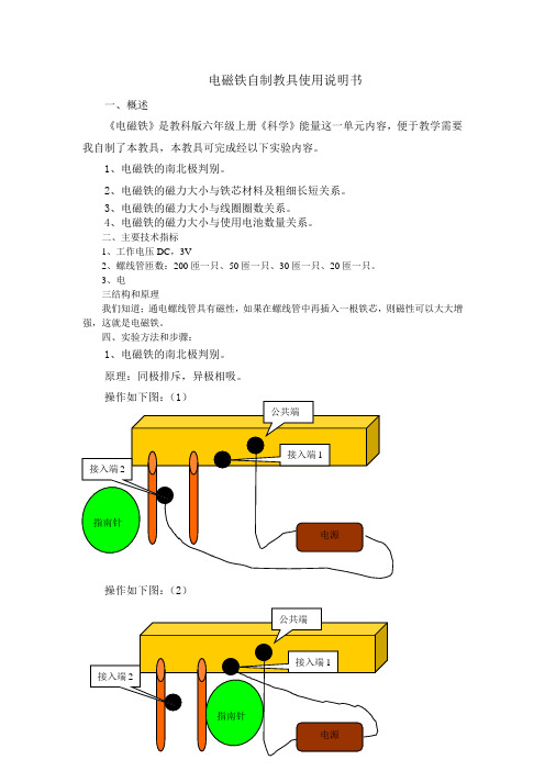
1、电磁铁的南北极判别。
原理:同极排斥,异极相吸。
操作如下图:(2)
附:方法可参照课本P49
2、电磁铁的磁力大小与铁芯材料及粗细长短关系。
操作如下图
1、按下面图,将电线接好。
3、电磁铁的磁力大小与线圈圈数关系。
过程:在50、30、20匝线管中放入铁芯,分别接通电源,根据吸上的小长针的多少判断磁力大小?电线接法如下图。
4、电磁铁的磁力大小与使用电池数量关系。
过程:放入铁芯,分别接通电源,如下图。
五、注意事项
1、实验时可用直流电源(大号电池),也可以使用学生电源。
2、接通电源时间不容可长,以免烧坏电源和线管,不使用时一定要断电。
3、不易儿童触摸。
202X人教版科学四年级下册第四章第1课《电磁铁的性质》ppt课件
又请看下面两个电磁铁有什么不同?
电池接法(正负极)不同
(S)
(N)
(—)
(N)
(+)
(S)
(+)
(—)
电磁铁性质(2): 电磁铁的南北极可以改变
(1)与线圈缠绕方向有关 (2)与电池的接法(正负极) 有关
改变线圈缠绕方向, 南北极会改变。
改变电池的接法 (正 负极),南北 极也会改变。
本课小结:
教案下载:/jiaoan/
PPT论坛:
PPT课件:/kejian/
语文课件:/kejian/yuw en/ 数学课件:/kejian/shuxue/
英语课件:/kejian/ying yu/ 美术课件:/kejian/me ishu/
17、儿童是中心,教育的措施便围绕 他们而 组织起 来。上 午7时25 分28秒 上午7 时25分0 7:25:28 21.5.3
谢谢观赏
You made my day!
我们,还在路上……
PPT图表:/tubiao/
PPT下载:/xiazai/
PPT教程: /powerpoint/
资料下载:/ziliao/
范文下载:/fanwen/
试卷下载:/shiti/
10、阅读一切好书如同和过去最杰出 的人谈 话。07:25:2807 :25:280 7:255/3 /2021 7:25:28 AM
11、一个好的教师,是一个懂得心理 学和教 育学的 人。21. 5.307:2 5:2807:25May -213-M ay -21
12、要记住,你不仅是教课的教师, 也是学 生的教 育者, 生活的 导师和 道德的 引路人 。07:25:2807:2 5:2807:25Mon day , May 03, 2021
电磁铁产品说明书

Dimensions: [mm]Scale - 2:1Scale - 1,5:176********768748015276874801527687480152T e m p e r a t u r eT T T 7687480152Cautions and Warnings:The following conditions apply to all goods within the product series of WE-TI-HV ofWürth Elektronik eiSos GmbH & Co. KG:General:•This electronic component is designed and manufactured for use in general electronic equipment.•Würth Elektronik must be asked for written approval (following the PPAP procedure) before incorporating the components into any equipment in fields such as military, aerospace, aviation, nuclear control, submarine, transportation (automotive control, train control, ship control), transportation signal, disaster prevention, medical, public information network, etc. where higher safety and reliability are especially required and/or if there is the possibility of direct damage or human injury.•Electronic components that will be used in safety-critical or high-reliability applications, should be pre-evaluated by the customer. •The component is designed and manufactured to be used within the datasheet specified values. If the usage and operation conditions specified in the datasheet are not met, the wire insulation may be damaged or dissolved.•Do not drop or impact the components, the component may be damaged.•Würth Elektronik products are qualified according to international standards, which are listed in each product reliability report. Würth Elektronik does not warrant any customer qualified product characteristics beyond Würth Elektroniks’ specifications, for its validity and sustainability over time.•The responsibility for the applicability of the customer specific products and use in a particular customer design is always within the authority of the customer. All technical specifications for standard products also apply to customer specific products.Product specific:Soldering:•The solder profile must comply with the technical product specifications. All other profiles will void the warranty.•All other soldering methods are at the customers’ own risk.Cleaning and Washing:•Washing agents used during the production to clean the customer application might damage or change the characteristics of the wire insulation, marking or plating. Washing agents may have a negative effect on the long-term functionality of the product. Potting:•If the product is potted in the customer application, the potting material might shrink or expand during and after hardening. Shrinking could lead to an incomplete seal, allowing contaminants into the core. Expansion could damage the component. We recommend a manual inspection after potting to avoid these effects.Storage Conditions:• A storage of Würth Elektronik products for longer than 12 months is not recommended. Within other effects, the terminals may suffer degradation, resulting in bad solderability. Therefore, all products shall be used within the period of 12 months based on the day of shipment.•Do not expose the components to direct sunlight.•The storage conditions in the original packaging are defined according to DIN EN 61760-2.•The storage conditions stated in the original packaging apply to the storage time and not to the transportation time of the components. Packaging:•The packaging specifications apply only to purchase orders comprising whole packaging units. If the ordered quantity exceeds or is lower than the specified packaging unit, packaging in accordance with the packaging specifications cannot be ensured. Handling:•Violation of the technical product specifications such as exceeding the nominal rated current will void the warranty.•Applying currents with audio-frequency signals may result in audible noise due to the magnetostrictive material properties.•Due to heavy weight of the components, strong forces and high accelerations may have the effect to damage the electrical connection or to harm the circuit board and will void the warranty.•Please be aware that products provided in bulk packaging may get bent and might lead to derivations from the mechanical manufacturing tolerances mentioned in our datasheet, which is not considered to be a material defect.•The temperature rise of the component must be taken into consideration. The operating temperature is comprised of ambient temperature and temperature rise of the component.The operating temperature of the component shall not exceed the maximum temperature specified.These cautions and warnings comply with the state of the scientific and technical knowledge and are believed to be accurate and reliable.However, no responsibility is assumed for inaccuracies or incompleteness.Würth Elektronik eiSos GmbH & Co. KGEMC & Inductive SolutionsMax-Eyth-Str. 174638 WaldenburgGermanyCHECKED REVISION DATE (YYYY-MM-DD)GENERAL TOLERANCE PROJECTIONMETHODTRi001.0002021-03-02DIN ISO 2768-1mDESCRIPTIONWE-TI HV Radial Leaded WireWound Inductor (High Voltage)ORDER CODE7687480152SIZE/TYPE BUSINESS UNIT STATUS PAGEImportant NotesThe following conditions apply to all goods within the product range of Würth Elektronik eiSos GmbH & Co. KG:1. General Customer ResponsibilitySome goods within the product range of Würth Elektronik eiSos GmbH & Co. KG contain statements regarding general suitability for certain application areas. These statements about suitability are based on our knowledge and experience of typical requirements concerning the areas, serve as general guidance and cannot be estimated as binding statements about the suitability for a customer application. The responsibility for the applicability and use in a particular customer design is always solely within the authority of the customer. Due to this fact it is up to the customer to evaluate, where appropriate to investigate and decide whether the device with the specific product characteristics described in the product specification is valid and suitable for the respective customer application or not.2. Customer Responsibility related to Specific, in particular Safety-Relevant ApplicationsIt has to be clearly pointed out that the possibility of a malfunction of electronic components or failure before the end of the usual lifetime cannot be completely eliminated in the current state of the art, even if the products are operated within the range of the specifications.In certain customer applications requiring a very high level of safety and especially in customer applications in which the malfunction or failure of an electronic component could endanger human life or health it must be ensured by most advanced technological aid of suitable design of the customer application that no injury or damage is caused to third parties in the event of malfunction or failure of an electronic component. Therefore, customer is cautioned to verify that data sheets are current before placing orders. The current data sheets can be downloaded at .3. Best Care and AttentionAny product-specific notes, cautions and warnings must be strictly observed. Any disregard will result in the loss of warranty.4. Customer Support for Product SpecificationsSome products within the product range may contain substances which are subject to restrictions in certain jurisdictions in order to serve specific technical requirements. Necessary information is available on request. In this case the field sales engineer or the internal sales person in charge should be contacted who will be happy to support in this matter.5. Product R&DDue to constant product improvement product specifications may change from time to time. As a standard reporting procedure of the Product Change Notification (PCN) according to the JEDEC-Standard inform about minor and major changes. In case of further queries regarding the PCN, the field sales engineer or the internal sales person in charge should be contacted. The basic responsibility of the customer as per Section 1 and 2 remains unaffected.6. Product Life CycleDue to technical progress and economical evaluation we also reserve the right to discontinue production and delivery of products. As a standard reporting procedure of the Product Termination Notification (PTN) according to the JEDEC-Standard we will inform at an early stage about inevitable product discontinuance. According to this we cannot guarantee that all products within our product range will always be available. Therefore it needs to be verified with the field sales engineer or the internal sales person in charge about the current product availability expectancy before or when the product for application design-in disposal is considered. The approach named above does not apply in the case of individual agreements deviating from the foregoing for customer-specific products.7. Property RightsAll the rights for contractual products produced by Würth Elektronik eiSos GmbH & Co. KG on the basis of ideas, development contracts as well as models or templates that are subject to copyright, patent or commercial protection supplied to the customer will remain with Würth Elektronik eiSos GmbH & Co. KG. Würth Elektronik eiSos GmbH & Co. KG does not warrant or represent that any license, either expressed or implied, is granted under any patent right, copyright, mask work right, or other intellectual property right relating to any combination, application, or process in which Würth Elektronik eiSos GmbH & Co. KG components or services are used.8. General Terms and ConditionsUnless otherwise agreed in individual contracts, all orders are subject to the current version of the “General Terms and Conditions of Würth Elektronik eiSos Group”, last version available at .Würth Elektronik eiSos GmbH & Co. KGEMC & Inductive SolutionsMax-Eyth-Str. 174638 WaldenburgGermanyCHECKED REVISION DATE (YYYY-MM-DD)GENERAL TOLERANCE PROJECTIONMETHODTRi001.0002021-03-02DIN ISO 2768-1mDESCRIPTIONWE-TI HV Radial Leaded WireWound Inductor (High Voltage)ORDER CODE7687480152SIZE/TYPE BUSINESS UNIT STATUS PAGE。
科学家实验室电磁钢磁场仪用户指南说明书

3B SCIENTIFIC ® PHYSICSElectromagnet Accessory for Zeeman Effect 1021365Instruction manual11/17 TL/UD1 Axle pin2 Sliding foil3 Pole piece with PE terminal4 Pole piece with stepped hole 5Pair of clamps1. Safety instructionsAttraction by strong magnetic fields can cause the pole pieces to damage the cadmium lamp. ∙Make sure that the pair of screws (safety locks) for both pole pieces are externally flush against the arms of the U-shaped magnet core (Fig. 2).It is possible for the electromagnet to tip over due to its own weight when secured to optical bench D (1002628) by means of optical base D (1009733). ∙ Stabilise the optical bench with the help of a set of feet for optical bench D (1012399). ∙Before putting the cadmium lamp attached to the electromagnet into operation, always ensure first that the PE socket is connected to the ballast and the pole piece with the PE terminal by means of the yellow and green safety lead (protective earth conductor).2. DescriptionThe electromagnet accessory makes up a spe-cial kit intended for the experiment to demon-strate the normal Zeeman effect. It provides a low-friction rotating bearing between the U-shaped core D (1000979) and the optical base D (1009733) and allows pole pieces and the base plate for the cadmium lamp (1021366) to be attached to the U-shaped core D.3. Equipment supplied1 Pole piece with PE terminal 1 Pole piece with stepped hole2 Clamps 1 Axle pin 1 Sliding foilFig. 1: Fully assembled electromagnet with cadmium lamp attached.4. Technical dataPole piece with PE terminalDimensions: 40 x 40 x 70 mm3Pole piece with stepped hole:Dimensions: 40 x 40 x 70 mm3 Diameter ofstepped hole: 5 – 20 mmClamps:Dimensions: 95 x 52 x 16 mm3 approx. Axle pin:Dimensions: 8 x 80 mm2Thread: M8 x 14 mmWeight: 1.6 kg approx.5. Additionally required equipment1 U-shaped core D 10009792 Coils D, 900 turns 1012859 1 Optical base D 1009733 1 Optical bench D, 100 cm 1002628 1 Set of feet for optical bench D 1012399 1 Cadmium lamp with accessories 1021366 1 DC power supply, 1 – 32 V, 0 – 20 A@230 V 1012857 1 Set of 15 experiment leads, 1002840 75 cm, 1mm2In countries with 110-120 V mains voltage, a power supply unit corresponding to the power supply unit 1012857 is required.6. Set-up∙Screw the axle pin as far as possible into the optical base by hand.∙First slip the slide foil with hole and then the U-shaped core with hole onto the axle pin and place them all on the optical base.∙Put the coils onto the arms of the U-shaped core as shown in Fig. 1.∙Put the pole pieces onto the arms of the U-shaped core as shown in Fig. 1. Make sure that the conical poles themselves are direct-ly opposite one another and that the flat ends of the pole pieces are flush against the arms of theU-shaped coil (Fig. 2). Use the two pairs of screws to help with the position-ing.Fig. 2: Pole piece correctly attached to U-shaped core.3B Scientific GmbH ▪ Rudorffweg 8 ▪ 21031 Hamburg ▪ Germany ▪ As well as helping with positioning, the two pairs of screws also act as safety locks. This ensures that the pole pieces do not damage the cadmi-um lamp when attracted by strong magnetic fields.∙ Attach the cadmium lamp as described inthe instruction manual for the cadmium lamp and accessories (1021366).∙ Make sure that the PE socket is connectedto the ballast and pole pieces with the yellow and green safety experiment lead (protective earth conductor).∙ Connect the two coils to the DC power sup-ply with opposing pola rities (connect the “0” and “900” taps in each case) (Fig. 1).The magnetic flux density depends on the current flowing through the electromagnet and can be determined using the calibration curve in Fig. 3. Note:Use the output with the 4-mm safety sockets on the front of the DC power supply and for output currents of 0 – 5 A. For output currents of 0 – 20 A use the pole terminal outputs on the back of the DC power supply.7. Storage, cleaning and disposal∙ Keep the equipment in a clean, dry and dust-free place.∙ Before cleaning the equipment, disconnect it from its power supply.∙ Do not use any aggressive cleaning agents or solvents to clean the equipment. ∙ Use a soft, damp cloth for cleaning.∙The packaging should be disposed of at lo-cal recycling points.∙Should you need to dispose of the equip-ment itself, never throw it away in normal domestic waste. If be-ing used in private households it can be disposed of at the local public waste disposalauthority.∙Comply with the applicable regulations for the disposal of electrical equipment.1234567891011120100200300400500600700800B / mT I / AFig. 3 Calibration curve for electromagnets when coils are connected with opposing polarity. Width of air gap 10 mm.。
Siemens SIRIUS Soft 74436412200 电磁铁说明书
Dimensions: [mm]Scale - 1:17443641220074436412200744364122007443641220074436412200T e m p e r a t u r eT pT L74436412200Cautions and Warnings:The following conditions apply to all goods within the product series of WE-HCF of Würth Elektronik eiSos GmbH & Co. KG:General:•This electronic component was designed and manufactured for use in general electronic equipment.•Würth Elektronik must be asked for written approval (following the PPAP procedure) before incorporating the components into any equipment in fields such as military, aerospace, aviation, nuclear control, submarine, transportation (automotive control, train control, ship control), transportation signal, disaster prevention, medical, public information network, etc. where higher safety and reliability are especially required and/or if there is the possibility of direct damage or human injury.•Electronic components that will be used in safety-critical or high-reliability applications, should be pre-evaluated by the customer. •The component was designed and manufactured to be used within the datasheet specified values. If the usage and operation conditions specified in the datasheet are not met, the wire insulation may be damaged or dissolved.•Do not drop or impact the components, as the core may flake apart.•Würth Elektronik products are qualified according to international standards, which are listed in each product reliability report. Würth Elektronik does not guarantee any customer qualified product characteristics beyond Würth Elektroniks’ specifications, for its validity and sustainability over time.•The customer is responsible for the functionality of their own products. All technical specifications for standard products also apply to customer specific products.Product specific:Soldering:•The solder profile must comply with the Würth Elektronik technical soldering specification. All other profiles will void the warranty. •All other soldering methods are at the customers’ own risk.Cleaning and Washing:•Washing agents used during the production to clean the customer application may damage or change the characteristics of the wire insulation, marking or plating. Washing agents may have a negative effect on the long-term functionality of the product. Potting:•If the product is potted in the costumer application, the potting material may shrink or expand during and after hardening. Shrinking could lead to an incomplete seal, allowing contaminants into the core. Expansion could damage the core or wire contacts. Werecommend a manual inspection after potting to avoid these effects. Storage Conditions:• A storage of Würth Elektronik products for longer than 12 months is not recommended. Within other effects, the terminals may suffer degradation, resulting in bad solderability. Therefore, all products shall be used within the period of 12 months based on the day of shipment.•Do not expose the components to direct sunlight.•The storage conditions in the original packaging are defined according to DIN EN 61760-2.Packaging:•The packaging specifications apply only to purchase orders comprising whole packaging units. If the ordered quantity exceeds or is lower than the specified packaging unit, packaging in accordance with the packaging specifications cannot be ensured. Handling:•Violation of the technical product specifications such as exceeding the nominal rated current will void the warranty•Applying currents with audio-frequency signals may result in audible noise due to the magnetostrictive material properties. •Due to heavy weight of the components, strong forces and high accelerations may have the effect to damage the electrical connection or to harm the circuit board and will void the warranty.These cautions and warnings comply with the state of the scientific and technical knowledge and are believed to be accurate and reliable.However, no responsibility is assumed for inaccuracies or incompletenessWürth Elektronik eiSos GmbH & Co. KGEMC & Inductive SolutionsMax-Eyth-Str. 174638 WaldenburgGermanyCHECKED REVISION DATE (YYYY-MM-DD)GENERAL TOLERANCE PROJECTIONMETHODElGa004.0002023-04-26DIN ISO 2768-1mDESCRIPTIONWE-HCF SMT High CurrentInductor ORDER CODE74436412200SIZE/TYPE BUSINESS UNIT STATUS PAGEImportant NotesThe following conditions apply to all goods within the product range of Würth Elektronik eiSos GmbH & Co. KG:1. General Customer ResponsibilitySome goods within the product range of Würth Elektronik eiSos GmbH & Co. KG contain statements regarding general suitability for certain application areas. These statements about suitability are based on our knowledge and experience of typical requirements concerning the areas, serve as general guidance and cannot be estimated as binding statements about the suitability for a customer application. The responsibility for the applicability and use in a particular customer design is always solely within the authority of the customer. Due to this fact it is up to the customer to evaluate, where appropriate to investigate and decide whether the device with the specific product characteristics described in the product specification is valid and suitable for the respective customer application or not.2. Customer Responsibility related to Specific, in particular Safety-Relevant ApplicationsIt has to be clearly pointed out that the possibility of a malfunction of electronic components or failure before the end of the usual lifetime cannot be completely eliminated in the current state of the art, even if the products are operated within the range of the specifications.In certain customer applications requiring a very high level of safety and especially in customer applications in which the malfunction or failure of an electronic component could endanger human life or health it must be ensured by most advanced technological aid of suitable design of the customer application that no injury or damage is caused to third parties in the event of malfunction or failure of an electronic component. Therefore, customer is cautioned to verify that data sheets are current before placing orders. The current data sheets can be downloaded at .3. Best Care and AttentionAny product-specific notes, cautions and warnings must be strictly observed. Any disregard will result in the loss of warranty.4. Customer Support for Product SpecificationsSome products within the product range may contain substances which are subject to restrictions in certain jurisdictions in order to serve specific technical requirements. Necessary information is available on request. In this case the field sales engineer or the internal sales person in charge should be contacted who will be happy to support in this matter.5. Product R&DDue to constant product improvement product specifications may change from time to time. As a standard reporting procedure of the Product Change Notification (PCN) according to the JEDEC-Standard inform about minor and major changes. In case of further queries regarding the PCN, the field sales engineer or the internal sales person in charge should be contacted. The basic responsibility of the customer as per Section 1 and 2 remains unaffected.6. Product Life CycleDue to technical progress and economical evaluation we also reserve the right to discontinue production and delivery of products. As a standard reporting procedure of the Product Termination Notification (PTN) according to the JEDEC-Standard we will inform at an early stage about inevitable product discontinuance. According to this we cannot guarantee that all products within our product range will always be available. Therefore it needs to be verified with the field sales engineer or the internal sales person in charge about the current product availability expectancy before or when the product for application design-in disposal is considered. The approach named above does not apply in the case of individual agreements deviating from the foregoing for customer-specific products.7. Property RightsAll the rights for contractual products produced by Würth Elektronik eiSos GmbH & Co. KG on the basis of ideas, development contracts as well as models or templates that are subject to copyright, patent or commercial protection supplied to the customer will remain with Würth Elektronik eiSos GmbH & Co. KG. Würth Elektronik eiSos GmbH & Co. KG does not warrant or represent that any license, either expressed or implied, is granted under any patent right, copyright, mask work right, or other intellectual property right relating to any combination, application, or process in which Würth Elektronik eiSos GmbH & Co. KG components or services are used.8. General Terms and ConditionsUnless otherwise agreed in individual contracts, all orders are subject to the current version of the “General Terms and Conditions of Würth Elektronik eiSos Group”, last version available at .Würth Elektronik eiSos GmbH & Co. KGEMC & Inductive SolutionsMax-Eyth-Str. 174638 WaldenburgGermanyCHECKED REVISION DATE (YYYY-MM-DD)GENERAL TOLERANCE PROJECTIONMETHODElGa004.0002023-04-26DIN ISO 2768-1mDESCRIPTIONWE-HCF SMT High CurrentInductor ORDER CODE74436412200SIZE/TYPE BUSINESS UNIT STATUS PAGE。
3B SCIENTIFIC 强磁铁运动实验器材说明书
3B SCIENTIFIC ®PHYSICS1Instructions d'utilisation05/18 ALF1 Douilles de jonction2 Aimant3 Axe 4RailCet appareillage permet de démontrer le mouvement de roulement exercé par un conducteur parcouru par du courant dans le champ magnétique d'un aimant permanent.L'appareil se compose d'un aimant puissant en forme de U disposé sur une plaque de base ainsi que d'une paire de rails en laiton au complet avec des douilles de 4 mm et d'un axe en laiton.Un bloc d'alimentation est connecté aux rails. Le circuit électrique est complété en plaçant l'axe sur les rails; l'axe sera alors repoussé le long des rails en direction ou en contre-direction du champmagnétique. Le renversement du courant produira l'effet contraire.Dimensions:env. 175x65x70 mm³ Tension de service :de 6 volts au max.1 Alimentation CC 0 - 20 V, 0 - 5 A@230 V, 50/60 Hz 1003312 ou@115 V, 50/60 Hz 1003311∙ Raccordez le bloc d'alimentation aux douilles de jonction des rails. ∙ Placez l'axe sur les rails.∙Allumez le bloc d'alimentation, appliquez une tension de 6 volts au maximum, puis observez le mouvement de l'axe.L'illustration 1 visualise le montage schématique de l'appareillage. Les lignes du champ magnétique se plaçant perpendiculairement par rapport à la direction du courant, l'axe se déplace alors perpendiculairement aussi bien par rapport au champ magnétique qu'à la direction du courant. Si nous inversons la direction des lignes3B Scientific GmbH ▪ Rudorffweg 8 ▪ 21031 Hamburg ▪ Allemagne ▪ Sous réserve de modifications techniques © Copyright 2018 3B Scientific GmbHdu champ magnétique ou celle du courant, l'axe se déplacera alors dans la direction opposée. La règle de la main gauche permet de déterminer la direction du mouvement prise par l'axe (comparer à l'illustration 2). Tenez le pouce, l'index et majeur de votre main gauche afin qu'ils forment un angle droit les uns par rapport aux autres. L'index représente alors la direction des lignes du champ magnétique, le majeur la direction du courant et le pouce la direction du mouvement.Fig. 1 : Montage schématique (a : direction des lignes du champ magnétique, b : direction du courant, c : direction du mouvement)Fig. 2 : Règle de la main gauche (a : direction des lignes du champ magnétique, b : direction du courant, c : direction du mouvement)。
人教版九年物理20.3电磁铁电磁继电器(共38张PPT)
把两个不同匝数的螺线管,串联 在同一电路中。
观察现象
结论:
电流一定时,线圈匝数越多, 电磁铁的磁性越强。
3.探究:影响电磁铁磁性强弱 的因素 设疑:
如果把铁芯取出来,电磁铁 的磁性会变化吗?用实验验证 你的猜想是否正确。
结论:
有铁芯时,电磁铁磁性增强。
三、电磁铁的应用
总结电磁铁有哪些优点:
1、磁性的有无可以用电流的 通断来控制. 2、磁性强弱可以用改变电流 的大小和线圈的匝数来控制。 3、它的磁极可以通过改变电 流的方向来控制。
电磁继电器作用 1. 电磁继电器是利用低电压、弱电流
电路的通断,来间接地控制高电压、强 电流电路的通断。
2.可以实现远距离操作和自动化控制
四、电磁继电器
水位自动报警装置是怎样连接并工作的? 要求:1、水位未达到金属块A时,绿灯亮;
电磁感应综合演示器的制作与使用
电磁感应综合演示器的制作与使用申报人姓名刘玉海申报学科物理联系方式23143814电磁感应综合演示器的制作与使用物理刘玉海摘要制作与使用,综合性较强。
能将高中“电磁感应”章节中电磁感应的各种现象和规律演示出来,能够满足中学演示教学的要求. 演示的内容有:⒈磁场部分:匀强磁场的演示.⒉电磁感应部分:可从不同角度来研究电磁感应现象产生的原因和条件.⒊发电机和电动机部分;该仪器配有发电机和电动机模型,专门用来演示交直流发电机和电动机的工作原理.关键词设计制作综合性强一仪多用满足中学演示教学电磁感应综合演示器的制作与使用天津一中刘玉海电磁感应综合演示器,是一种物理教学综合性演示仪器,它能将高中“电磁感应”章节中电磁感应的各种现象和规律演示出来。
其结构紧凑、简单合理,不用连接线路,操作简单,可见度大,节省演示实验时间;能够满足中学演示教学的要求。
一、仪器的组成结构及使用的材料仪器的结构分主体和附体两部分,主体为立式结构,又分正反两面:⒈原付线圈;原线圈在原有4层基础上用0.5mm漆包线再平绕2层使接通电源后磁性增加,付线圈在原有6层绕线基础上再平绕7层。
在6层于7层中间加按键开关,付线圈开始和接尾加装插孔接线柱便于接演示电表,以便能够演示付线圈导线长度变化后,闭合电路中的感生电流的变化增大。
⒉改制的200Ω滑动变阻器;利用废旧的50Ω滑动变阻器散件拼装成一个骨架,用康铜丝绕满骨架,阻值大约在200Ω左右接在电路中用来迅速改变闭合电路中电流的大小。
⒊可改变磁性大小的磁棒;用5N圆桶测力计的外筒及螺旋端盖,里面装直径1.8cm,长5cm铝柱,在铝柱上粘6块高强磁性磁铁,磁铁三块为一组,中间用塑料板隔开,方便取出三块来改变磁性大小。
筒外贴上红蓝两色不干胶纸显示磁极性。
再在磁棒上端连接3N螺旋弹簧,使用时挂在主板上部,磁棒下端穿进付线圈中使磁棒能在付线圈中上下振动。
⒋指示感生电流方向及大小的发光二极管面板;用一块6×15cm塑料板,在上下两端分别并联三个二极管(红绿各三个)然后引出插接柱,以便于插在付线圈上利用发光二极管的单向导电发光以及发光的亮暗来显示感生电流的方向和大小。
202X人教版九年级物理第3节 电磁铁 电磁继电器1课件

观察电路可知:这个报警器的工作原理是: 有人踩踏板时__电__铃__响__;无人踩踏板时 __电__灯__亮__。
动手动脑学物理
1.水位没有到达金属块A时,继电器线圈没有电 流通过,它的上面两个触点接触,工作电路中绿灯与 电源构成回路,绿灯亮; 当水位到达金属块A时, 继电器线圈有电流流过, 它的下面两个触点接触, 工作电路中红灯与电源 构成回路,红灯亮。
2、电磁继电器的结构包括哪些,各有什么作用?
3、实际生活中的电磁继电器,哪些接线柱接高 压,哪些接线柱接低压?
1.电磁继电器
(1)电磁继电器的构造
衔铁
触点
弹
电
簧
磁
铁
电 磁 继 电 器
常见的几种电磁继电器:
(2)电磁继电器的工作原理
电源
低压控制电路
电 源 电动机
高压工作电路
工作原理
➢ 电磁铁通电时,把衔铁吸下来使D和E接触, 工作电路闭合。电磁铁断电时失去磁性,弹 簧把衔铁拉起来,切断工作电路。
实验: 研究电磁铁
器材:线圈匝数可以改变的电磁铁,滑动变阻器, 电流表,电源,开关,导线和一小堆大头针
步骤: (1) 电磁铁的磁性跟电流通断的关系 (2)电磁铁的磁性强弱跟电流大小的关系 (3)电磁铁的磁性强弱跟线圈匝数的关系
(1)研究电磁铁的磁性有无 实验 闭合和断开开关
现象 通电时电磁铁 吸__引__大__头__针___ 断电时电磁铁 不__吸__引__大__头__针__
2.温度升高时,水银面上升,当水银面上升到 与金属接触时,电磁线圈就有电流流过,产生磁性 吸引触点开关使之闭合,这时工作电路就形成了一 个回路,电铃就响起来了。
电磁铁使用说明书

电磁铁使用说明书一、产品简介电磁铁是一种利用电流在导线中产生磁场从而产生吸引力的设备。
本产品采用高质量的铁芯和导线制造而成,具备强大的磁性吸附能力。
本使用说明书将详细介绍电磁铁的正确使用方法和注意事项,以确保您的安全和产品的正常运行。
二、安全警告请在操作电磁铁之前,仔细阅读并理解以下安全警告,以避免潜在的危险或意外伤害:1. 在操作电磁铁之前,请确保已断开电源并进行安全隔离,以防止电流通路中发生意外触电。
2. 为避免磁铁吸附过程中产生的强烈震动而导致周围物体的破碎或飞出,请谨慎选择安装位置并保持安全距离。
3. 使用电磁铁时,请避免将金属物品直接放置在皮肤上,以免产生不必要的吸附或损伤。
4. 在使用过程中,如发生异常情况(如异响、发热等),请立即停止使用,并向售后服务部门寻求帮助。
三、使用步骤请按照以下步骤正确操作电磁铁:1. 安装:将电磁铁固定在坚固平整的平面上,确保其稳定性。
2. 连接电源:使用标准电源线将电磁铁连接到电源插座,确认电源连接正确无误。
3. 开启电源:打开电源开关,使电流通过导线产生磁场。
4. 吸附物品:将需要吸附的金属物品靠近电磁铁的铁芯部分,确保物品与铁芯之间无障碍,并尽量使物品与铁芯接触面积最大化。
5. 关闭电源:在使用完成后,关闭电源开关,切断电流供应。
6. 分离物品:在断电后,缓慢将吸附的物品离开电磁铁,注意避免碰撞或拉扯,确保安全分离。
四、使用注意事项请遵守以下注意事项,以确保电磁铁的正常使用和延长其使用寿命:1. 请勿将电磁铁放置在高温、潮湿、腐蚀性气体或易燃物质附近,以免损坏设备。
2. 在使用过程中,如发现电磁铁发热、冒烟或发出异常噪声,请立即停止使用并断开电源。
3. 请勿将电磁铁长时间放置在强磁场或震动环境中,以免影响其性能。
4. 请勿试图自行拆卸或修理电磁铁,如有需要,请联系售后服务部门或专业人士进行维修。
五、保养与维护1. 请定期检查电磁铁的电源线是否破损或老化,如发现问题,请及时更换以避免电流泄露。
自制电动机演示仪教具说明书

自制电动机演示仪
教具说明书
教具名称:磁场对通电导线的作用演示仪或自制电动机演示仪。
制作者:zhaowenyv
制作时间:2015.12
制作原理:通电导线在磁场中受到力的作用。
制作材料:直径1cm的圆柱形强磁铁、1节五号电池、1条直径1.5mm的铜线。
制作方法:取约32cm长的铜线弯成如上图“心”的形状,铜线的两端分别弯成半圆,两个半圆组合,刚好形成一个小的圆圈,并且这个圆圈的直径要稍大于圆柱形强磁铁的直径。
教具用途:用于九年级物理全一册(人教社)第二十章第4节《电动机》这一节课的实验演示。
通过改变电池的正负极或磁铁的方向,引起心形铜线旋转方向的改变,从而说明以下结论:通电导线在磁场中要受到力的作用,力的方向跟电流的方向、磁感线的方向都有关系,当电流的方向或磁感线的方向变得相反时,通电导线的受力也变得相反。
教具特点:制作简单,操作方便,效果明显。
实验演示网址链接:https:///s/KhdKDGYjE-bGsozFh8TYjw。
科学实验用品 电磁铁 电子产品 电子实验用品 实验用电磁铁说明书
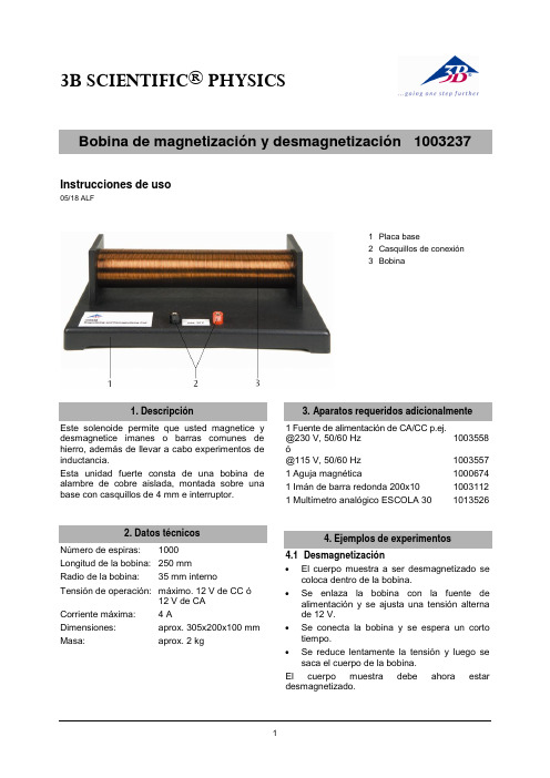
3B SCIENTIFIC ® PHYSICS1Instrucciones de uso05/18 ALF1 Placa base2 Casquillos de conexión3 BobinaEste solenoide permite que usted magnetice y desmagnetice imanes o barras comunes de hierro, además de llevar a cabo experimentos de inductancia.Esta unidad fuerte consta de una bobina de alambre de cobre aislada, montada sobre unabase con casquillos de 4 mm e interruptor. Número de espiras: 1000 Longitud de la bobina: 250 mmRadio de la bobina: 35 mm internoTensión de operación: máximo. 12 V de CC ó12 V de CA Corriente máxima: 4 ADimensiones: aprox. 305x200x100 mm³ Masa:aprox. 2 kg1 Fuente de alimentación de CA/CC p.ej. @230 V, 50/60 Hz 1003558 ó@115 V, 50/60 Hz 1003557 1 Aguja magnética 1000674 1 Imán de barra redonda 200x10 10031121 Multímetro analógico ESCOLA 30 1013526 4.1 Desmagnetización∙ El cuerpo muestra a ser desmagnetizado secoloca dentro de la bobina.∙ Se enlaza la bobina con la fuente dealimentación y se ajusta una tensión alterna de 12 V.∙ Se conecta la bobina y se espera un cortotiempo.∙ Se reduce lentamente la tensión y luego sesaca el cuerpo de la bobina.El cuerpo muestra debe ahora estar desmagnetizado.3B Scientific GmbH ▪ Rudorffweg 8 ▪ 21031 Hamburgo ▪ Alemania ▪ Nos reservamos el derecho a cambios técnicos© Copyright 2018 3B Scientific GmbH4.2 Magnetización∙ El cuerpo muestra a ser magnetizado (p. ej.barra de hierro) se coloca dentro de la bobina.∙ La bobina se enlaza con la fuente dealimentación y se ajusta una tensión continua de 12 V.∙ Se conecta la bobina y se espera un cortotiempo. Luego se saca lentamente el cuerpo muestra de la bobina.El cuerpo muestra debe estar ahora magnetizado.4.3 Producción de un campo magnético∙ Se coloca la aguja magnética en un extremode la bobina.∙ La bobina se enlaza con la fuente dealimentación y se ajusta una tensión continua.∙ Se aumenta lentamente la tensión en lafuente de alimentación se observa la desviación de aguja magnética.4.4 Demostración de la inducción∙ El multímetro se conecta en los casquillos dela bobina.∙ Se ajusta la indicación en “punto cero encentro de la escala”.∙ El conmutador de alcances se ajusta en“Tensión CC“ y se selecciona un alcance de medida bajo.∙ El imán de barra redonda se mueve envaivén dentro de la bobina y al mismo tiempo se observa la indicación en el multímetro.。
- 1、下载文档前请自行甄别文档内容的完整性,平台不提供额外的编辑、内容补充、找答案等附加服务。
- 2、"仅部分预览"的文档,不可在线预览部分如存在完整性等问题,可反馈申请退款(可完整预览的文档不适用该条件!)。
- 3、如文档侵犯您的权益,请联系客服反馈,我们会尽快为您处理(人工客服工作时间:9:00-18:30)。
电磁铁性质演示器
作者:李兴超
单位:济南市济阳县姜集小学
一、作品简介
本作品为小学科学演示用自制教具,可做适合小学生认知水平的电磁铁性质演示实验。
本作品主要由电池盒、组合式电磁铁、电流表、磁针、测力计、闸刀开关及底座组成,具有结构设计合理、操作方便、实验效果明显、制作成本低等优点。
二、创作背景
本作品的设想开始于执教《通电的
线圈》一课之时。
现有的学生分组实验
器材虽然能够让学生在充分动手动脑
的基础上得到实验结果,但教师演示实
验也是必不可少的。
由于教师做此演示
实验时,课堂组装实验器材较为繁琐;
同时,在研究磁力大小时使用吸大头钉
的方法比较危险。
因此,我决定自制一
套电磁铁性质演示实验装置来解决上
述问题,设计思路为将相关实验器材集
成到一套装置中,合理布局,并使用测
力计来代替吸大头钉的实验方法。
三、使用方法
(一)磁力大小测定:
将电磁铁置于“磁力测定区”,把
电磁铁的一端吸合测力计底部,匀速下
拉,记录测力计弹回时的指示数据。
可
通过改变线圈匝数(改变线圈组数)或改变电池数量(改变电池组正极引线位置即可)等方法进行研究。
(二)磁极测定:
将电磁铁置于“磁极测定区”,将电磁铁卡在支架上,接通电源,观察磁针所指方向。
可通过改变正负极(线圈接线柱正负极换位)或改变绕线方向(将两组线圈从铁芯上同时取下,换方向安装即可)等方法来进行研究。
四、创新性
(一)将与研究电磁铁性质相关的实验器材集成到一套装置中,并利用合理布局、器材相互利用等措施,使实验装置操作更为简便、现象更为明显、资源更为节约;
(二)在改变电磁铁线圈匝数、改变绕线方向等操作时,不需要将繁琐的电线解开重新绕制,而是只需通过改变接线位置、将线圈组取下反装即可实现。
(三)新设计的用测力计测磁力的方式更为简单、安全、直观。
五、项目的使用情况和进一步完善的设想
该项目已在本学校六年级两个班进行了实际教学使用,效果较为明显、课堂效率有明显提高。
通过课堂使用发现了测力计标记较小、磁针较小等缺点,对课堂效果有一定的影响,下一步我将把本装置的标记设计更为明显,并能进行壁挂演示。