Jeffcott转子-轴承系统的非线性动力学特性分析
5自由度磁悬浮轴承—转子系统非线性动力学研究
5自由度磁悬浮轴承—转子系统非线性动力学研究张钢;殷庆振;蒋德得;梁世颇【期刊名称】《机械工程学报》【年(卷),期】2010()20【摘要】为了探讨磁悬浮轴承—转子系统的稳定性,从非线性多自由度的角度对5自由度主动磁悬浮轴承—转子系统的非线性动力学特性进行研究。
在考虑电磁力、重力和不平衡力周期性影响的情况下,建立5自由度磁浮轴承—转子系统的动力学模型,通过泰勒公式对其进行非线性展开,运用多尺度法的基本原理对5自由度非线性微分方程进行复数处理。
通过Matlab软件编程,借助庞加莱映射图和相图对系统的运动形态进行分析,得到在复数领域中的倍周期运动、拟周期运动和混沌运动的相图及庞加莱映射截面图。
在试验过程中也发现,随着转速的增加,磁悬浮轴承—转子系统的轴心轨迹由有规律的稳定运动状态进入无规律的失稳运动状态。
数值模拟和试验结果都表明:磁悬浮轴承—转子系统中存在丰富的非线性动力学现象,在不同参数条件下,系统存在稳定的倍周期运动、临界的拟周期运动和失稳的混沌运动现象。
【总页数】7页(P15-21)【关键词】5自由度;磁悬浮轴承;转子系统;非线性动力学【作者】张钢;殷庆振;蒋德得;梁世颇【作者单位】上海大学机电工程与自动化学院【正文语种】中文【中图分类】TH133.3【相关文献】1.主动磁悬浮轴承-转子系统的非线性动力学研究 [J], 张钢;梁世颇;殷庆振;张彪;刘莹;刘汝卫2.大自由度的转子-滑动轴承系统非线性动力学分析(Ⅱ) [J],3.大自由度的转子—滑动轴承系统非线性动力学分析 [J], 李志刚;张直明4.磁悬浮转子-轴承碰摩系统的非线性动力学行为 [J], 徐璐;饶晓波;褚衍东5.大自由度的转子-滑动轴承系统非线性动力学分析(Ⅱ) [J], 李志刚;张直明因版权原因,仅展示原文概要,查看原文内容请购买。
文献翻译-非线性动力学的实验和转子轴承系统支持的行为的数值研究

附录A英文原文Experimental and Numerica Studies on Nonlinear Dynam Behavior of Rotor System Supported by Ball BearingsBall bearings are important mechanical components in high-speed turbomachinery that is liable for severe vibration and noise due to the inherent nonlinearity of ball ing experiments and the numerical approach, the nonlinear dynamic behavior of a flexible rotor supported by ball bearings is investigated in this paper. An experimental ball bearing-rotor test rig is presented in order to investigate the nonlinear dynamic performance of the rotor systems, as the speed is beyond the first synchroresonance frequency. The finite element method and two-degree-of-freedom dynamic model of a ball bearing are employed for modeling the flexible rotor s ystem. The discrete model of a shaft is built with the aid of the finite element technique, and the ball bearing model includes the nonlinear effects of the Hertzian contact force, bearing internal clearance, and so on.The nonlinear unbalance response is observed by experimental and numerical analysis.All of the predicted results are in good agreement with experimental data, thus validating the proposed model. Numerical and experimental results show that the resonance frequency is provoked when the speed is about twice the synchroresonance frequency, while the subharmonic resonance occurs due to the nonlinearity of ball bearings and causes severe vibration and strong noise. The results show that the effect of a ball bearing on the dynamic behavior is noticeable in optimum design and failure diagnosis of high-speed turbomachinery. [DOI: 10.1115/1.4000586]Keywords: ball bearing, rotor, experiment, nonlinear vibrationA.1 IntroductionBall bearings are one of the essential and important components in sophisticated turbomachinery such as rocket turbopumps, aircraft jet engines, and so on. Because of the requirement of acquiring higher performance in the design and operation of ballbearings-rotor systems, accurate predictions of vibration characteristics of the systems, especially in the high rotational speed condition, have become increasingly important.Inherent nonlinearity of ball bearings is due to Hertzian contact forces and the internal clearance between the ball and the ring.Many researchers have devoted themselves to investigating the dynamiccharacteristics associated with ball bearings. Gustafsson et al. [1] studied the vibrations due to the varying compliance of ball bearings. Saito [2] investigated the effect of radial clearance in an unbalanced Jeffcott rotor supported by ball bearings using the numerical harmonic balance technique. Aktürk et al. [2] used a three-degree-of-freedom system to explore the radial and axial vibrations of a rigid shaft supported by a pair of angular contact ball bearings. Liew et al. [4] summarized four different dynamic models of ball bearings, viz., two or five degrees of freedom, with or without ball centrifugal force, which could be applied to determine the vibration response of ball bearing-rotor systems. Bai and Xu [5] presented a general dynamic model to predict dynamic properties of rotor systems supported by ball bearings. De Mul et al. [6] presented a five-degree-of-freedom (5DOF) model for the calculation of the equilibrium and associated load distribution in ball bearings. Mevel and Guyader [7] described different routes to chaos by varying a control parameter. Jang and Jeong [8] proposed an excitation model of ball bearing waviness to investigate the bearing vibration. Then, considering the centrifugal force and gyroscopic moment of ball, they developed an analytical method to calculate the characteristics of the ball bearing under the effect of waviness in Ref. [9]. Tiwari et al. [10,11] employed a two-degree-of-freedom model to analyze the nonlinear behaviors and stability associated with the internal clearance of a ball bearing.Harsha [12-14], taking into account different sources of nonlin-earity, investigated the nonlinear dynamic behavior of ball bearing-rotor systems. Gupta et al. [15] studied the nonlinear dynamic response of an unbalanced horizontal flexible rotor supported by a ball bearing. With the aid of the Floquet theory, Bai et al. [16] investigated the effects of axial preload on nonlinear dynamic characteristics of a flexible rotor supported by angular contact ball bearings. Using the harmonic balance method, Sinou [17]performed a numerical analysis to investigate the nonlinear unbalance response of a flexible rotor supported by ball bearings.In the abovementioned studies, main attention has been paid to the ball bearing modeling and the dynamic properties analysis according to simple bearing-rotor models. With theoretical analysis and experiment, Yamamoto et al. [18] studied a nonlinear forced oscillation at a major critical speed in a rotating shaft,which was supported by ball bearings with angular clearances.Ishida and Yamamoto [19] studied the forced oscillations of a rotating shaft with nonlinear spring characteristics and internal damping. They found that a self-excited oscillation appears in the wide range above the major critical speed. A dynamic model was derived, and experiments are carried out with a laboratory test rig for studying the misaligned effect of misaligned rotor-ball bearing systems in Ref. [20]. Tiwari et al. [21] presented an experimental analysis to study the effect of radial internal clearance of a ball bearing on the bearingstiffness of a rigid horizontal rotor. These experimental results validated theoretical results reported in their literatures [10,11]. Recently, Ishida et al. [22] investigated theoretically and experimentally the nonlinear forced vibrations and parametrically excited vibrations of an asymmetrical shaft supported by ball bearings. Mevel and Guyader [23] used an experimental test bench to confirm the predicted routes to chaos in their previous paper [7]. It is noticeable of lack of experiments on nonlinear dynamic behavior of flexible rotor systems supported by ball bearings. In Ref. [24], the finite element method was used to model a LH2 turbopump rotor system supported by ball bearings. Numerical results show that the subharmonic resonance, as well as synchroresonance, occurs in the start-up process. It is found that the subharmonic resonance is an important dynamic behavior and should be considered in engineering ball bearing-rotor system design. But, the experimental and numerical studies of the subharmonic resonance in ball bearing-rotor systems are very rare.With respect to the above, the present study is intended to cast light on the subharmonic resonance characteristics in ball bearing-rotor systems using experiments and numerical approach. An experiment on an offset-disk rotor supported by ball bearings is carried out, and the finite element method and two-degree-of-freedom model of a ball bearing are employed for modeling this rotor system. The predicted results are compared with the test data, and an investigation is conducted in the nonlinear dynamic behavior of the ball bearings-rotor system.2 Experimental InvestigationAn experimental rig is employed for studying the nonlinear dynamic behavior of ball bearing-rotor systems, as shown in Fig.1. The horizontal shaft is supported by two ball bearings at both ends, and the diskis mounted unsymmetrically. The shaft is coupled to a motor with a flexible coupling. The motor speed is controlled with a feedback controller, which gets the signals from an eddy current probe. Four eddy current probes, whose resolution is 0.5 m, are mounted close to the disk and bearing at the right end in the horizontal and vertical directions, respectively. The displacement signals, obtained with the help of probes, are input into an oscilloscope to describe the motion orbit, and a data acquisition and processing system were used to analyze the effects of ball bearings on the nonlinear dynamic behavior. The data acquisition and processing system utilizes a full period sampling as the data acquisition method. Its sampling rate is 500 kHz maximum, and sample size is 12 bits. The system provides eight channels for vibratory response acquisition and 1 channel for rotational speed acquisition. All channels are simultaneous.The limitation with the presented experimental setup is that the maximum attainable speed is 12,000 rpm. The first critical speed of the rotor system falls in the speed span, as the shaft is flexible and its fist synchroresonance frequency is near 66 Hz (3960rpm).Thus, the dynamic behavior can be studied as the speed is beyond twice the synchroresonance frequency.3 Rotor Dynamic ModelThe bearing-rotor system combines an offset-disk and two ball bearings, which support the rotor at both ends. The sketch map of the system is described in Fig. 2, where the frame oxyz is the inertial frame. The corresponding experiment assembly is shown in Fig. 3.3.1 Equations of Motion . Define ux and uy as the transverse deflections along the ox and oy directions, and x θ and y θ as the corresponding bending angles in the oxz and oyz planes, respectively. When x u 1, y u 1,x 1θ , and y 1θ denote the displacements of the ball bearing center location at the left end, the complex variables 1u and 1θ can be assumed asDenote the displacements of the disk center by 2u and 2θ, and the displacements of the ball bearing center location at the right end by 3u and 3θ. Using the finite element method, the equations of motion for the rotor system can be written as [25,26]where []M , []C , []K , and []G are the mass, damping, stiffness, and gyroscopic matrix of the rotor system, respectively, ω is the rotational speed, and {}u is the displacement vector{}g F and {}u F are the vectors of gravity load and unbalance forces.{}bF is the vector of nonlinear forces associated with ball bearings.3.2 Ball Bearing Forces. A ball bearing is depicted in a frame of axes oxyz in Fig.4. The contact deformation for the j-th rolling element j δis given aswhere i c and o c are the internal radial clearance between the inner,outer race, and rolling elements, respectively, in the direction of contact, and ubx and uby are the relative displacements of the inner and outer race along the x and y directions, respectively. As shown in Fig. 4, the angular location of the j-th rolling element j ϕ can be obtained fromWhere N , c ω, t , and 0ϕ are the number of rolling elements, cage angular velocity, time, and initial angular location, respectively. The cage angular velocity can be expressed as [27]where b D and p D are the ball diameter and bearing pitch diam- eter,respectively. α is the contact angle, which is concerned with the clearance and can be obtained as follows:Referring to Fig. 4, i r and o r are the inner and outer groove radius,respectively.If the contact deformation j δ is positive, the contact force could be calculated using the Hertzian contact theory; otherwise, no load is transmitted. The contact force j Q between the j-th ball and race can be expressed as follows:where b k is the contact stiffness that can be given bywhere bi k and bo k are the load-deflection constants between the inner and outer ball race, respectively[28]. Summing the contact forces for each rolling element, the total bearing reaction fb in a complex form is4 Experimental and Numerical AnalysisAs shown in Fig. 2, the experimental assembly and the finite element model used in the dynamic analysis represent the ball bearing-rotor system with the following geometrical properties:length between the disk center and left end bearing center mm L 1201=; length between the disk center and right end bearing center mm L 1202=; and the shaft diameter mm D 10=. In addition, the elastic shaft material is steel of density 37950m kg =ρ,Young’s modulus GPa E 211=, and Poisson’s ratio 3.0=v . The ball bearings at both ends are the same model, 7200AC, and its parameters are listed in Table 1.The unbalance load is acted wit h the aid of the mass fixed on the disk. By virtue of this act, the mass eccentricity of the disk can be definitely ascertained. As the mass eccentricity of the disk is 0.032 mm, the vibratory response at different rotational speed is determined via a numerical integration and Newton –Raphson iterations of the nonlinear differential equation (2). Note that the clearances used to simulate the bearings are measured ones. The horizontal and vertical displacements signals near the disk are acquired at different times, along with the increased rotational speed. Thus, the amplitudes of vibration at different speeds are determined according to the test data, and overall amplitudes are illustrated in Fig. 5, as the rotor system is run from 2000=ω rpm to 10,000 rpm. The prediction results compared with experimental data are shown in Fig. 5. It can be found that all of the predicted results are in good agreement with experimental data, thus validating the proposed model. The first predicted resonance peak—the so called forward critical speed in linear theory,located at3960=ω rpm, matches the experimental date near 3960=ω rpm quite well. Moreover, the other amplitude peak appearing in the rotational speedrange7700=ω rpm to 8100 rpm can be found in both experimental and numerical analysis results.The corresponding frequency value of this peak is just the frequency doubling of the system critical speed.The Floquet theory can be used for analyzing the stability and topological properties of the periodic solution of the ball bearingrotor system. If the gained Floquet multipliers are less than unity,the periodic solution of the system is stable. If at least one Floquet multiplier exists with the absolute value higher than unity, the periodic solution is unstable and the topological properties of response alter into nonperiodic motion [29]. The leading Floquet multipliers and its absolute value at 7600=ω rpm, 8029 rpm, and 8200 rpm are shown in Table 2. It is found that the leading Floquet multiplier of the system remains in the unit circle, which indicates a synchronous response, as the rotational speed is less than 7700 rpm. Stability analysis shows that the imaginary part of the two leading Floquet multipliers move in opposite directions along the real axis near 7700=ω rpm. When the speed exceeded 7700=ω rpm, the leading Floquet multiplier crosses the unit circle through -1, as shown in Table 2. The periodic solution loses stability and undergoes a period-doubling bifurcation to a period-2 response, which indicates that a subharmonicresonance occurs. The subharmonic resonance keeps on from 7700=ω rpm to 8100 rpm. At 8100=ω rpm, the leading Floquet multiplier moves inside the unit circle through -1. Imply that the subharmonic resonance vanishes and the synchronous response returns. The synchronous response then continues to exist forspeeds above 8100=ω rpm.The waterfall map of frequency spectrums comparisons for prediction and experiment results are illustrated in Fig. 6. It can be found that agreement between the prediction and the experimental data is remarkable. The frequency component 66.9 Hz, near the forward resonance frequency, emerges and its amplitude rises significant when the rotational speed is near 8029 rpm. It is shown that the resonance frequency is provoked when the speed is about twice the critical speed of the ball bearing-rotor system, and the subharmonic resonance occurs. The experimental and numerical analysis indicate that the representative nonlinear behavior and the subharmonic resonance arise from the nonlinearity of ball bearings, Hertzian contact forces, and internal clearance.The orbit and frequency spectrum at 8029=ω rpm are plotted in Fig. 7. Not only the prediction orbit but also the experiment results imply that the response is a period-2 motion, which is illustrated in Fig. 7(a). The predicted frequency components, consisting of 8.133=ω Hz (8029 rpm) and 9.662=ω Hz (4014rpm), coincide with experimental data. It indicates that the periodic response loses stability through a period-doubling bifurcation to a period-2 response. Thus, the subharmonic resonance occurs due to the effects of ball bearings. It can cause severe vibration and strong noise. Moreover, the subharmonic resonance could couple with other destabilizing effects on engineering rotor systems such as Alford forces, internal damping, and so on, and induce the rotor to lose stability and damage.5 ConclusionsAn experimental rig is employed to investigate the nonlinear dynamic behavior of ball bearing-rotor systems. The corresponding dynamic model is established wi th the finite element method and 2DOF dynamic model of a ball bearing, which includes the nonlinear effects of the Hertzian contact force and bearing internal clearance. All of the predicted results are in good agreement with experimental data, thus validating the proposed model. Numerical and experimental results show that the resonance frequency is provoked, and the subharmonic resonance occurs due to the nonlinearity of ball bearings when the speed is about twice the synchroresonance frequency. The subharmonic resonance cannot only cause severe vibration and strong noise, but also induce the rotor to lose stability and damage, once coupled with other destabilizing effects on high-speed turbomachinery such as Alford forces, internal damping, and so on. It is found that the effect of the Hertzian contact forces could also induce a subharmonic resonance, even if the internal clearance was not present. But, the response amplitude and subharmonic component of the rotor system without internal clearance are less than that with both Hertzian contact forces and internal clearance. Otherwise, the clearance may be unavoidable under high-speed operations, where the bearings are axially preloaded since the effect of unbalanced load is significant at high speed. Thus, the nonlinearity of ball bearings,Hertzian contact forces, and internal clearance should be taken into account in ball bearing-rotor system design and failure diagnosis.AcknowledgmentThe authors would like to acknowledgment the support of the National Natural Science Foundation of China (Grant No.10902080) and Natural Science Foundation of Shaanxi Province(Grant Nos. SJ08A19 and 2009JQ1008).References[1] Gutafsson, O., and Tallian, T., 1963, “Resear ch Report on Study of the Vibration Characteristics of Bearings,” SKF Ind. Inc. Technical Report No.AL631023.[2] Saito, S., 1985, “Calculation of Non-Linear Unbalance Response of Horizontal Jeffcott Rotors Supported by Ball Bearings With Radial Clearances,” ASME J.Vib., Acou st., Stress, Reliab. Des., 107(4), pp. 416–420.[3] Aktürk, N., Uneeb, M., and Gohar, R., 1997, “The Effects of Number of Balls and Preload on Vibrations Associated With Ball Bearings,” ASME J. Tribol.,119, pp. 747–753.[4] Liew, A., Feng, N., and Hahn, E., 2002, “Transient Rotordynamic Modeling of Rolling Element Bearing Systems,” ASME J. Eng. Gas Turbines Power,124(4), pp. 984–991.[5] Bai, C. Q., and Xu, Q. Y., 2006, “Dynamic Model of Ball Bearing With Internal Clearance and Waviness,” J. Sound Vib., 294(1-2), pp. 23–48.[6] De Mul, J. M., Vree, J. M., and Maas, D. A., 1989, “Equilibrium and Associated Load Distribution in Ball and Roller Bearings Loaded in Five Degrees of Freedom While Neglecting Friction—Part I: General Theory and Application to Ball Be arings,” ASME J. Tribol., 111, pp. 142–148.[7] Mevel, B., and Guyader, J. L., 1993, “Routes to Chaos in Ball Bearings,” J.Sound Vib., 162, pp. 471–487.[8] Jang, G. H., and Jeong, S. W., 2002, “Nonlinear Excitation Model of Ball Bearing Waviness in a Rigid Rotor Supported by Two or More Ball Bearings Considering Five Degrees of Freedom,” ASME J. Tribol., 124, pp. 82–90.[9] Jang, G. H., and Jeong, S. W., 2003, “Analysis of a Ball Bearing With Waviness Considering the Centrifugal Force and Gyroscopic Moment of the Ball,”ASME J. Tribol., 125, pp. 487–498.[10] Tiwari, M., Gupta, K., and Prakash, O., 2000, “Effect of Radial Internal Clearance of a Ball Bearing on the Dynamics of a Balanced Horizontal Rotor,” J.Sound Vib., 238(5), pp. 723–756.[11] Tiwari, M., Gupta, K., and Prakash, O., 2000, “Dynamic Response of an Unbalanced Rotor Supported on Ball Bearings,” J. Sound Vib., 238(5), pp.757–779.[12] Harsha, S. P., 2005, “Non-Linear Dynamic Response of a Balanced Rotor Supported on Rolling Element Bearings,” Me ch. Syst. Signal Process., 19(3),pp. 551–578.[13] Harsha, S. P., 2006, “Rolling Bearing Vibrations—The Effects of Surface Waviness and Radial Internal Clearance,” Int. J. Computational Methods in Eng Sci. and Mech., 7(2), pp. 91–111.[14] Harsha, S. P., 2006, “Nonlinear Dynamic Analysis of a High-Speed Rotor Supported by Rolling Element Bearings,” J. Sound Vib., 290(1–2), pp. 65–100.[15] Gupta, T. C., Gupta, K., and Sehqal, D. K., 2008, “Nonlinear Vibration Analysis of an Unbalanced Flexible Rotor Supported by Ball Bearings With Radial Internal Clearance,” Proceedings of the ASME Turbo Expo, Vol. 5, pp. 1289–1298.[16] Bai, C. Q., Zhang, H. Y., and Xu, Q. Y., 2008, “Effects of Axial Preload of Ball Bearing on theNonlinear Dynamic Characteristics of a Rotor-Bearing System,” Nonlinear Dyn., 53(3), pp. 173–190. [17] Sinou, J. J., 2009, “Non-Linear Dynamics and Contacts of an Unbalanced Flexible Rotor Supported on Ball Bearings,” Mech. Mach. Theory, 44(9), pp.1713–1732.[18] Yamamoto, T., Ishida, Y., and Ikeda, T., 1984, “Vibrations of a Rotating Shaft With Rotating Nonlinear Restoring Forces at the Major Critical Speed,” Bull.JSME, 27(230), pp. 1728–1736.[19] Ishida, Y., and Yamamoto, T., 1993, “Forced Oscillations of a Rotating Shaft With Nonlinear Spring Characteristics and Internal Damping (1/2 Order Subharmonic Oscillations and Entrainment),” Nonlinear Dyn., 4(5), pp. 413–431.[20] Lee, Y. S., and Lee, C. W., 1999, “Modeling and Vibration Analysis of Misaligned Rotor-Ball Bearing Systems,” J. Sound Vib., 224(1), pp. 17–32.[21] Tiwari, M., Gupta, K., and Prakash, O., 2002, “Experimental Study of a Rotor Supported by Deep Groove Ball Bearing,” Int. J. Rotating Mach., 8(4), pp.243–258.[22] Ishida, Y., Liu, J., Inoue, T., and Suzuki, A., 2008, “Vibrations of an Asymmetrical Shaft With Gravity and Nonlinear Spring Characteristics (IsolatedResonances and Internal Resonances),” ASME J. Vib. Acoust., 130(4),p.041004.[23] Mevel, B., and Guyader, J. L., 2008, “Experiments on Routes to Chaos in Ball Bearings,” J. S ound Vib., 318, pp. 549–564.[24] Bai, C. Q., Xu, Q. Y., and Zhang, X. L., 2006, “Dynamic Properties Analysis of Ball Bearings—Liquid Hydrogen Turbopump Used in Rocket Engine,”ACTA Aeronaut. Astronaut. Sinica, 27(2), pp. 258–261. [25] Nelson, H., 1980, “A Finite Rotating Shaft Element Using Timoshenko Beam Theory,” ASME J. Mech. Des., 102(4), pp. 793–803.[26] Zhang, W., 1999, Basis of Rotordynamic Theory, Science Press, Beijing,China, Chap. 3.[27] Harris, T. A., 1984, Rolling Bearing Analysis, 2nd ed., Wiley, New York.[28] Aktürk, N., 1993, “Dynamics of a Rigid Shaft Supported by Angular Contact Ball Bearings,” Ph.D. thesis, Imperial College of Science, Technology and Medicine, London, UK.[29] Zhou, J. Q., and Zhu, Y. Y., 1998, Nonlinear Vibrations, Xi’an Jioatong University Press, Xi’an, China.附录B英文翻译非线性动力学的实验和转子轴承系统支持的行为的数值研究深沟球轴承在高速流体机械部件承担严重的振动和噪声的固有的非线性是很重要的。
转子—轴承系统的非线性动力学的研究
也 : oo —d mte; 0l I el; I∞6 ; h o rtr 3 is jI m Ⅱ ] hg 埘 I m cas  ̄ r
0 前
言
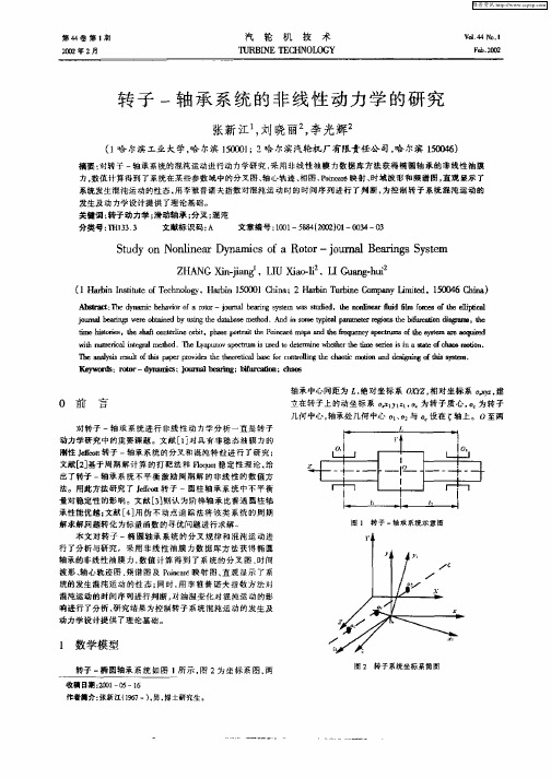
轴承 中心间距为 , 绝对 坐标 系 O Y 相 对坐标 系 D , X Z. 建 立在 ̄-  ̄的动坐 标 系 _ 1【 为 转子 质心 . 为转 子 y - 1 , Y 几何 中心 , 轴承处几何 中心 D 、2 1 D 与 设在 轴 上 0至两
T eaa h Il rslo ts l蛐 eut h f i №
poie h ho ta bs o otln h ho c rv st eri l a d et ec ef cn oi ecat r r lgt i
0 mdd嘲 l o t s yt I a e fi s m. l fs e
( 哈 尔滨工业大学, 尔滨 100 ; 哈 尔滨汽轮机厂有限责任公 司, 尔滨 1 06 1 哈 51l 2 3 哈 5 4) o
摘要 : 对转 子 一轴 承系统的混 沌运动进行动 力学研 究 , 用非线性 油膜 力数据 库方法 获得椭 圆轴承 的非线性 油膜 采 力. 数值 计算得到 了系统在某些参数域 中的分叉图 、 轴心轨迹 、 相图 、o er P i a ̄映射、 n 时域 波形和频 谱图 , 直观 显示 了
对 转子 一轴 承系统 进行 非线 性动 力学分 析一直是 转子
动力学 研究 中的重要课题 。文献 [ 1 对具 有非稳态 油膜力的 刖性 J et转子 一轴承系统 的分 叉和 混沌特 性进行 了研究 ; dr t o
文献[3 2基于周期 解计算 的打靶法 和 F qe稳定 性理论 , l ut o 给
维普资讯
第 4卷 第 1 4 期
机床主轴_滚动轴承系统非线性动力学分析

振 动 与 冲 击第27卷第9期JOURNAL OF V I B RATI O N AND SHOCKVol .27No .92008 机床主轴2滚动轴承系统非线性动力学分析基金项目:国家重点基础研究发展计划“973”项目(2005CB724101)和国家自然科学基金项目(10702040)资助收稿日期:2007-12-14 修改稿收到日期:2008-02-01第一作者张伟刚男,硕士生,1981年生张伟刚, 高尚晗, 龙新华, 孟 光(上海交通大学机械系统与振动国家重点实验室,上海 200240) 摘 要:通过对机床主轴2滚动轴承系统的研究,建立了一个基于Hertz 接触力模型的6自由度系统动力学微分方程,初步探讨在非平衡力作用下,具有负游隙的机床主轴-滚动轴承系统的非线性动态特性和稳定性。
结果表明,由于游隙和变刚度的影响,随控制参数频数比的变化,系统将出现失稳和复杂的非线性现象;通过对比正、负游隙下的系统响应,可得到负游隙有助于提高机床主轴-滚动轴承系统稳定性的结论,该结论与其他学者[10]实验所证明的轴承预紧有助于提高主轴-轴承系统的固有频率,进而提高系统稳定性的结论相吻合。
关键词:滚动轴承;非线性动力学;游隙;稳定性中图分类号:O322;TH133 文献标识码:A 现代制造业对高速、高精度的要求使得我们有必要对机床主轴-轴承系统的非线性动态特性进行深入的分析和研究。
而轴承滚子和轴承内、外圈之间的非线性接触力是机床主轴-轴承系统振动响应的主要非线性因素。
为此,众多研究者在该非线性接触力对主轴-轴承系统动态特性的影响方面展开了广泛的研究。
Ya ma mot o [1]通过研究滚动轴承游隙对Jeffcott 转子振动特性的影响,发现其振动幅度会随着轴承游隙的增加而降低;在此工作基础上,Ti w ari 等[2-5]研究了轴承游隙及变刚度对非平衡Jeffcott 转子非线性动态特性的影响;Sopanen 和M ikkola [6,7]对转子-轴承系统建立了一个6自由度的力学模型,通过对该系统动力学模型的研究,分析游隙对系统固有频率和振动响应的影响;在以上的研究中,转速皆假定为常数,L i ouli os和Ant oniadis [8]研究变转速对转子-轴承系统动态特性的影响,结果表明:即使转子转速发生很小的波动,也可能导致系统动态特性发生很大变化。
含轴承内环间隙的转子非线性动力学建模
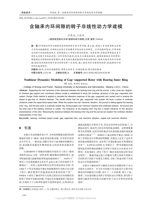
将内环间隙配合转子系统简化为盘-轴颈二自由度
(2) 得到:
k s1 =
间隙支承转子非线性碰撞模型ꎬ简化准则为:保留右端轴
B
(2)
a
= k s1
k s2 =
2
l
ab
式中:E s 是转子的弹性模量ꎻI s 是转子横截面积的惯性矩ꎮ
f0
D
a2 b2
3E s I s
颈的质量ꎬ忽略轴的质量ꎬ只考虑轴的刚度ꎮ 简化后的内
MATLAB 中的 ODE45 求解器求解ꎬ单盘转子系统参数如
表 1 所示ꎮ
表 1 单盘转子系统参数
颈轨迹离散点ꎮ
因为在动力学方程 中 很 难 表 述 图 4 所 示 的 碰 撞 模
转轴长度 l / m
转轴直径 / m
盘直径 / m
0.9
0.016
0.48
盘距左端距离 a / m
泊松比
密度 / (kg / m )
系统的 Jeffcott 方程ꎮ 结果表明:随着轴承间隙的增大ꎬ临
界转速的最大振幅和临界转速的值将减小
[1]
ꎮ SAITO S
[2]
研究了含径滚珠轴承支承水平 Jeffcott 转子的非线性不平
衡响应
[2]
ꎮ 虽然上述两项研究仅涉及谐波响应分析ꎬ但
动和组合振动 [4-5] ꎮ ISHIDA Y 通过谐波平衡法( HBM) 分
合ꎬ为了研究轴承内环间隙对转子动力学的影响ꎬ设计了
如图 1 所示的偏执单盘转子系统ꎮ 在转子右端支承处ꎬ采
用了含轴承内环间隙的装配方式ꎬ右端轴颈可以在间隙中
移动ꎮ
在非线性动力学建模过程中ꎬ引入如下假设:1) 轴承
无游隙ꎬ轴承外环和轴承座无间隙ꎬ轴承内环支承在弹性
有限宽轴承-转子系统碰摩的非线性动力学特性

( 2 )
在无量纲化 过程 中的 为油膜平均间隙,R为轴承半径, 为轴径长度 ,S o 为S mmefl数 , re d
叩 为润滑 动力粘度 , 为无量 纲转速 ,p 为无 量纲质量偏 心 , 为反映 了润滑油粘度 、轴承间隙 及长径 比等多种 因素影 响的一个综合参数。
动稳定 性的影响 。文 【 中介绍 了一种通过 变分原理得 到的有 限宽轴承 油膜力公式 ,此 方法具 7 1
有 较 深 的 数 学基 础 。
2 有 限 宽轴 承一 子 系 统 碰 摩 的非 线 性 动 力 学 模 型 转
对 于图 1 所示 的转子一 轴承结构 ,运用变分原理并经 过推 导得到的油膜力为
非 线性 动 力 学 现 象 ,为 解 决 实 际 工 程系 统 中遇 到 的 问题 ,如 故 障 诊 断 等 提 供 了一 定 的理 论 依 据 。 关键 词 :有 限 宽 轴 承一 子 :碰 摩 油 膜 力 :变 分 方 法 ; 非 线 性 动 力 学 转 中 图 分类 号 : 2 ; 03 2 TH13 3 文 献标 识 码 :A
m蕾= me O £ Q C S +厶 , m = me i £ 一mg Q Q s Q+ n
() 1
为使结果不受量纲影 响,从而具有更为普遍 的意义 ,按文【将方程() 8 ] 1 无量纲化 ,可 得 方 程() 1的无量纲形式为
:
鲁+c, : p . p 鲁+s 一. 。 s i 1 n 0
£ 为径 向位移, 和£ 分别为径 向速度和周 向速度 , 为油膜厚度 ,A 为长径 比,西 为姿态角 。
图1 中D为轴承 中心 ,0 为轴 径 中心 ,m为转子质量 之半 ,e 为转 子质量偏 心 ,Q 为轴径 的
弹性转子-轴承系统的非线性动力学研究

(2)该类转子一轴承系统在某一转速时在一定
偏心量作用下,具有发生不利于系统运行的分叉和 概周期运动的可能性,在该类转子设计和运行时要 使工作转速避开该类区域。
作者简介:张新江.1967年生.哈尔演工业大学能源学院动力机 械及工程专业博士研究生。
收稿日期:1999—12—24
Analysis of nonlinear dynamics to
疋/a圻=B/d为无量纲非线性油膜力分量,p为
润滑油枯度,G=gl-/∞2为无量纲外载荷,r=oJr 为无量纲时间,e为偏心量,c为轴承半径间隙,L为
轴承长度,置为轴承半径,d=篙警(詈)2(去)2为
口3=詈,正坼由文献[6]确定。
嘁ld修正数,m-・=里詈二旦,nI_0,。:=O生72,
个具有非线性油膜力的弹性转子一轴承系统稳态
I”一:小:(”柚+去正
卜一嚣九-言(,--y2)+知~。
I*:一盖t:一2。a。2(x:一t)+Pcosr
【舻一薏,:一警(y:-y1)叩inr—G
其中,托=Xz/c、yl=Yi/c为无量纲坐标,五=
值方法,对具有非线性油膜力的Jeffcott转子一轴承
系统进行了分叉研究;G.Adiletta[2,31从理论和试验 两方面进行了较为详细的论述;S.Boel曲I卅则认为阶 梯轴承比普通圆柱轴承性能优越;刘恒【51用伪不动 点追踪法将该系统的周期解求解问题转化为标量函 数的寻优问题进行求解。本文的主要工作是研究一
庞加莱映射方法对其动力学特性随莱一参数变化时稳定性的改变进行了分析,计算结果表明,系统 具有发生倍周期分又及概周期运动的可能。用数值方法得到系统在某些参数域中的分又图,直观显 示了系蜿在某盛参数城中的运行状态。
机动飞行器内碰摩转子的非线性动力学研究
机动飞行器内碰摩转子的非线性动力学研究
都昌兵;刘文娟
【期刊名称】《长沙航空职业技术学院学报》
【年(卷),期】2017(017)003
【摘要】建立了飞行器内支承在挤压油膜阻尼器上Jeffcott转子的碰摩数学模型,对其在匀速飞行和稳定盘旋两种情况下进行了数值分析.结果表明,机动飞行对转子系统的周期运动、拟周期运动、混沌运动的参数范围甚至稳定性有显著的影响,机动飞行使工作转速低时系统的稳定性降低.
【总页数】4页(P72-75)
【作者】都昌兵;刘文娟
【作者单位】长沙航空职业技术学院,湖南长沙 410124;长沙航空职业技术学院,湖南长沙 410124
【正文语种】中文
【中图分类】V214.33
【相关文献】
1.具有不平衡-碰摩耦合故障的转子-滚动轴承系统非线性动力学研究 [J], 陈果
2.飞行器内碰摩转子模型的光滑处理及非线性研究 [J], 林富生;孟光
3.碰摩故障转子-滚动轴承耦合系统非线性动力学研究 [J], 李飞敏;陈果
4.转子与定子碰摩的非线性动力学研究 [J], 江俊;陈艳华
5.含裂纹-碰摩气浮转子系统非线性动力学研究 [J], 王海飞;刘美红;田槐艳;宋兆哲
因版权原因,仅展示原文概要,查看原文内容请购买。
滚动轴承-转子系统非线性动力响应分析

滚动轴承-转子系统非线性动力响应分析陶海亮;潘波;高庆;郭宝亭;谭春青【摘要】采用有限元法建立了含转子不平衡-碰摩耦合故障的滚动轴承-转子系统的连续模型,考虑了转子的剪切效应、回转效应、转子几何参数等影响因素,对滚动轴承模型考虑了非线性赫兹接触及由滚动轴承支承刚度变化而产生的VC(Varying Compliance)振动.运用Newmark-β法获得了连续转子的系统响应,利用时域波形、分岔图、Poincare映射图和频谱图分析了该转子系统的非线性动力学行为.结果表明:由于不同参数的影响,转子碰摩系统具有丰富的非线性现象.本模型考虑了更多的影响因素,可为复杂转子的非线性设计、故障诊断提供更为准确合理的理论参考.【期刊名称】《燃气轮机技术》【年(卷),期】2013(026)001【总页数】6页(P15-20)【关键词】转子;滚动轴承;连续模型;非线性;分岔【作者】陶海亮;潘波;高庆;郭宝亭;谭春青【作者单位】中国科学院工程热物理研究所,北京100190;中国科学院轻型动力重点实验室,北京100190【正文语种】中文【中图分类】O322随着对旋转机械高转速、高效率的要求,转子与静子的间隙越来越小,使得转静碰摩成为转子动力学重要的研究方向[1]。
根据转子系统所采用的支承方式,转子-轴承非线性动力分析主要在以下两个方面进行:一方面,以滑动轴承为支承考虑非线性油膜力作用下转子各种故障的机理性分析;另一方面,以滚动轴承为支承考虑碰摩、偏心、不对中、基础松动、裂纹等相关故障的研究。
目前,滑动轴承-转子的动力特性已经有了比较深入的研究。
褚福磊等[2]用数值分析研究了滑动轴承-转子系统进入和离开混沌状态的路径。
焦映厚等[3]考虑了非线性油膜力,对转子系统的不平衡响应进行了非线性分析。
在对滚动轴承-转子系统的研究中,很多情况下将支承简化为刚度为常数的弹性支承[4-5],而没有考虑轴承间隙和由于滚珠和滚道的接触位置变化引起的轴承刚度周期变化导致的参数激振(即VC振动)。
五自由度磁悬浮轴承转子系统的非线性动力学研究

五自由度磁悬浮轴承转子系统的非线性动力学研究摘要:研究了五自由度主动磁悬浮轴承—转子系统的非线性动力学特性,考虑了系统非线性因素的影响,由Taylor级数展开得到非线性电磁力的表达式,建立了五自由度磁浮轴承转子系统动力学模型和空间状态方程,用数值积分法对其进行分析。
通过Matlab软件编程,借助庞加莱影射和Lyapunov指数对系统的运动形态进行分析,结果发现在一定参数条件下,系统会出现分叉和混沌现象。
关键词:五自由度;磁悬浮轴承;转子系统;非线性;动力学Research On Nonlinear Dynamics Of Five-dof rRotor –Amb SystemAbstract: To study the nonlinear dynamical behaviors of Five-DOF AMB system, system’s non-linear dynamic characteristics was considered. System’s non-linear dynamics mathematical model was established,and used Taylor formula to transform it to non-linear form. The space state equations was given and analyzed by numerical method. Through Matlab programming, Poincare maps were given and Lyapunov index were calculated, and they were used to analyze the system’s dy namical behaviors. The result show that there existed bifurcation and chaos in the system when there were some definite parameters..Key words: Five-DOF AMB, Rotor system, Nonlinear, Dynamics0 引言主动磁悬浮轴承在工程中有着广泛的应用,但由于其大多数组成部分具有非线性特性,因而构成了一个非线性机电系统。
迷宫密封-滚动轴承-悬臂转子系统非线性动力学特性分析
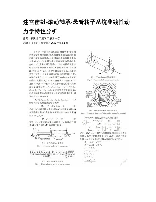
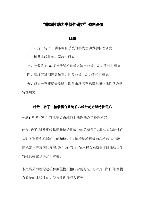
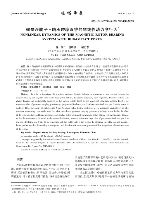
迷宫密封-滚动轴承-悬臂转子系统非线性动力学特性分析作者:罗跃纲王鹏飞王晨勇徐昊来源:《振动工程学报》2020年第02期摘要:對于带有迷宫密封的航空发动机转子系统气流激振问题,基于有限元理论,应用非线性滚动轴承支承力模型以及Muzynska密封力模型建立了两个滚动轴承支承的迷宫密封一悬臂转子系统动力学模型,并运用Newmark-β数值积分法求解得到系统在不同转速、偏心量和密封结构参数下的动力学响应特征。
研究结果表明,系统在一定转速范围内作周期一运动,随着转速的升高系统发生失稳并作拟周期运动;适当增大偏心量会导致转子在共振区出现偏心力所引起的短暂的混沌运动;增大密封间隙会使系统在高转速区重新回归周期一运动,而且失稳区域也随之减小;适当提高密封长度,系统仅表现为周期一运动,但继续增大密封长度,悬臂端承受密封圆盘的重量也将提高,失稳转速提前;另外还分析了失稳转速和密封力的影响因素及其影响规律,为转子系统的密封激振故障诊断及密封结构优化设计提供一定的理论依据。
关键词:非线性振动;悬臂转子系统;迷宫密封;密封力;有限元中图分类号:0322;0347.6文献标志码:A 文章编号:1004-4523(2020)02-0256-09DOI:10.16385/ki.issn.1004-4523.2020.02.005引言迷宫密封是普遍安装在现代航空发动机、汽轮机等旋转机械结构中的有效封严结构,它作为一种非接触式密封,具有结构简单、耗能小、使用寿命长、无需润滑等特点,其作用是减少轴端与各级问的流体泄漏损失。
对于带有迷宫密封的转子系统,由于工作转速的提高、转子柔性增大和高参数密封致使密封激振作用极易发生,并导致转子失稳。
因此,为加强该类系统的运行稳定性与工作安全性,研究含有密封激振力作用下的转子系统动力学特征并分析一些典型参数影响规律有着重要的意义。
多年以来,国内外许多专家学者在含有密封的转子动力学领域作了大量研究,比如在求解密封动力特性系数并分析其影响因素方面,wang等通过应用单控制体模型及摄动法对含有迷宫密封的转子系统进行动力学建模并对其进行计算;文献[2-3]利用cFX-TAscflow流体动力学软件计算了密封转子动力系数,并研究了它的影响因素等。
“非线性动力学特性研究”资料合集
“非线性动力学特性研究”资料合集目录一、叶片—转子—轴承耦合系统的非线性动力学特性研究二、桩基非线性动力学特性研究三、分数阶DCDC变换器解析建模方法与非线性动力学特性研究四、深埋隧道围岩系统稳定性及非线性动力学特性研究五、路面—车速耦合激励下四自由度汽车悬架系统非线性动力学特性研究叶片—转子—轴承耦合系统的非线性动力学特性研究标题:叶片-转子-轴承耦合系统的非线性动力学特性研究叶片-转子-轴承系统是现代旋转机械中的关键部分,其动力学特性直接影响到整个机器的性能和稳定性。
随着旋转机械向高转速、高精度、高稳定性等方向的发展,对叶片-转子-轴承耦合系统的非线性动力学特性的研究显得尤为重要。
本文将采用理论建模和数值模拟相结合的方法,对叶片-转子-轴承耦合系统的非线性动力学特性进行深入研究。
我们将建立一个包括叶片、转子和轴承的三元耦合模型。
该模型将充分考虑各部件的非线性特性,如叶片的气动弹性、转子的陀螺效应以及轴承的摩擦接触等。
我们还将引入适当的边界条件,以模拟系统的实际运行环境。
然后,我们将利用有限元方法和非线性动力学理论,对建立的模型进行数值模拟和分析。
通过改变系统的运行参数,如转速、负载、温度等,我们可以深入研究这些参数对系统非线性动力学特性的影响,以及系统可能出现的分岔、混沌等现象。
我们还将针对系统的非线性动力学特性进行控制策略的研究。
通过设计适当的控制算法和控制器,我们期望实现对系统非线性动力学特性的有效控制,从而提高旋转机械的整体性能和稳定性。
我们将对实验数据进行分析,验证理论模型和数值模拟结果的正确性。
通过对比实验结果和模拟结果,我们可以进一步优化我们的模型和控制策略,从而提高旋转机械的设计水平和运行效率。
在现代旋转机械的设计和优化过程中,对叶片-转子-轴承耦合系统的非线性动力学特性的深入理解和有效控制是至关重要的。
本文的研究旨在为这一重要课题提供新的理论框架和数值方法,从而为现代旋转机械的发展提供新的可能性和动力。
磁悬浮转子-轴承碰摩系统的非线性动力学行为
引言
近几年,磁悬以下特点: 完全消除了 磨损、无需润滑和密封、耐环境强、发热少、功耗低、圆 周转速高、可对转子位置进行控制、轴承动态特性好以
关键词 磁悬浮转子 辅助轴承 碰摩 振动 混沌 中图分类号 O322 TH122 Abstract In order to investigate the transient nonlinear dynamic behavior in connection to the contract between the auxiliary bearing and magnetic rotor under high-speed rotation,bifurcation diagrams,time responses,Poincaré sections and phrase diagrams are synthetically employed in the present article based on the numerical integration method. Firstly,the respective effect of geometric coupling parameter α,proportional feedback gain P and derivative feedback gain D on the system is explored. Then,the impact of stiffness ratio K and Coulomb sliding friction coefficient μ on unbalanced parameter U are also discussed respectively. The results show that when the value of geometric coupling parameter α is large,it can lead to the offset of the rotor from the equilibrium position,corresponding to the rub-impact phenomenon of the rotating rotor and auxiliary bearing so that the equipment is disturbed by the abnormal vibration,however,either the large value of proportional feedback gain P or derivative feedback gain D can be in connection with the stable state of the system. In addition,the softly mounted auxiliary bearing is beneficial to the stability of the system,and the choice of unbalanced parameter U has a significant effect on the state of the system. Key words Magnetic rotor; Auxiliary bearing; Rub-impact; Vibration; Chaos Corresponding author: XU Lu,E-mail: xljtedu@ sina.com The project supported by the National Natural Science Foundation of China ( No. 11161027,11262009) ,and the Research Fund for the Doctoral Program of Higher Education ( No. 20136204110001 ) , and the Lanzhou Talent Innovation and Entrepreneurship Project( No. 2015-RC-3) . Manuscript received 20180209,in revised form 20180724.
动量轮滚动轴承-转子系统非线性动力响应分析

动量轮滚动轴承-转子系统非线性动力响应分析朱玉鹏;朱川峰;谢鹏飞;于晓凯;杨茹萍【摘要】建立了考虑非线性轴承力的动量轮轴承-转子系统动力学方程,并采用Runge-Kutta数值方法对其求解.利用分岔图、Poincare映射图、幅值谱图依次分析了不同转速、等效阻尼、径向游隙状态下系统动力学响应特征.分析结果表明:滚动轴承-转子系统具有丰富的周期、拟周期以及混沌的响应形式.混沌响应中存在变柔度振动,且x方向较为剧烈.合理选择滚动轴承的参数组合,可使滚动轴承-转子系统处于较稳定的振动响应状态.【期刊名称】《河南科技大学学报(自然科学版)》【年(卷),期】2018(039)003【总页数】5页(P24-28)【关键词】滚动轴承-转子系统;非线性动力学;变柔度振动;振动响应【作者】朱玉鹏;朱川峰;谢鹏飞;于晓凯;杨茹萍【作者单位】河南科技大学土木工程学院,河南洛阳471023;洛阳轴研科技股份有限公司,河南洛阳471039;洛阳轴研科技股份有限公司,河南洛阳471039;洛阳轴研科技股份有限公司,河南洛阳471039;河南科技大学土木工程学院,河南洛阳471023【正文语种】中文【中图分类】TH133.33;O3220 引言动量轮广泛应用于航天、航空等领域的惯性制导系统中,承载着飞行器姿态调整和轨迹变换的重要任务,其主要由4部分组件构成:轴承组件、电机组件、壳体组件和轮体组件[1]。
轴承作为其主要传动部件,对动量轮寿命和性能影响重大。
超长时间的高速运转及复杂受力导致轴承在工作过程中会出现一些异常振动,传统的线性理论无法合理解释这种现象的存在,越来越多的专家学者开始用非线性理论进行分析 [2]。
目前,滚动轴承-转子系统的相关研究已取得较多成果。
文献[3]用简化的多自由度转子模型进行离心机轴承-转子系统模拟分析,考察了垂直放置转子在有无基础运动时的动力学性质。
文献[4-5]研究了时变非线性刚度对轴承稳定性的影响。
碰摩转子—轴承系统非线性动力学行为研究
碰摩转子—轴承系统非线性动力学行为研究
李振平;张金换;金志浩;闻邦椿
【期刊名称】《航空动力学报》
【年(卷),期】2004(19)2
【摘要】为了充分揭示碰摩转子系统复杂的非线性动力学行为,将多初始点分岔分析方法应用于碰摩转子—轴承系统的研究当中。
通过对给定参数下转子系统响应的数值模拟,发现了比单初始点算法更加丰富的非线性现象,在一定的参数范围内该碰摩转子系统有多吸引子共存,并对解的演化过程进行了研究,结果很好地解释了碰摩转子系统中一些复杂的非线性现象。
【总页数】5页(P179-183)
【关键词】碰摩;转子—轴承系统;非线性动力学;多初始点分岔分析方法;拟周期;油膜压力
【作者】李振平;张金换;金志浩;闻邦椿
【作者单位】清华大学汽车安全与节能国家重点实验室;东北大学机械工程与自动化学院
【正文语种】中文
【中图分类】O347.6
【相关文献】
1.具有不平衡-碰摩耦合故障的转子-滚动轴承系统非线性动力学研究 [J], 陈果
2.非线性连续转子轴承系统碰摩故障动力学行为研究 [J], 李朝峰;李小彭;马辉;闻
邦椿
3.碰摩故障转子-滚动轴承耦合系统非线性动力学研究 [J], 李飞敏;陈果
4.轴承座受冲击条件下转子系统碰摩动力学行为研究 [J], 贺少华;吴新跃
5.磁悬浮转子-轴承碰摩系统的非线性动力学行为 [J], 徐璐;饶晓波;褚衍东
因版权原因,仅展示原文概要,查看原文内容请购买。
三种非线性油膜力模型的分析比较1)

三种非线性油膜力模型的分析比较1)王晋麟曹登庆2)王立刚黄文虎(哈尔滨工业大学航天学院,137 信箱,哈尔滨150001)摘要:本文分析比较了三种具有解析表达式的圆轴承非线性油膜力模型,对比了建立油膜力时,Reynolds 方程及其边界条件所采用的假设条件,并以200MW汽轮发电机低压转子为例,比较了不同油膜力模型对系统非线性行为的影响,并分析了产生各种差异的因素。
关键词:转子―轴承;汽轮机;非线性振动;油膜振荡中图分类号:TH133 O3220引言转子―轴承系统非线性动力学行为研究是转子动力学中较为活跃的一个领域。
基于八个油膜动特性系数的线性油膜力模型[1]已经发展得较为完善并获得了广泛的应用。
为了提高发电效率、节约能源、保护环境,汽轮发电机的主力机组从亚临界到超临界、超超临界转型,已经成为必然的选择。
同时,由于发电机转速的提高、结构的轻型化和大柔性使得转子―轴承系统中的非线性因素越来越显著,以小扰动为前提的线性油膜力模型已不再适用。
从20世纪80年代起,转子―轴承系统的非线性油膜失稳问题逐渐引起科学家与工程师们的重视。
建立一个既能较为准确地反映轴承中的油膜力,又简单实用的解析的非线性油膜力模型是研究转子―轴承系统非线性动力学现象的关键。
对圆轴承,从基本的Reynolds方程出发,基于静态Gümbell假设,可以导出无限短轴承和无限长轴承的π油膜力模型的解析表达式[2]。
Muszynska[3]提出用表征流体的周向流速的量来建立非线性的油膜力模型,并据此分析了转子―轴承系统的稳定性。
1991年Capone[4]提出修正的短轴承假设下的非线性油膜力模型,该模型的计算结果表明,它具有较好的精度和收敛性。
张文等[5,6]提出了动态π油膜力模型,它用三个非线性函数描述油膜力,并在短轴承假设下获得了非稳态非线性油膜力的解析表达式。
张文等[7]于2002年进一步提出了非线性油膜力的一般表达式,其瞬态刚度阵和瞬态阻尼阵由三个非线性函数来描述,并通过变分法给出了有限长椭圆轴承的高精度近似解析式。
微极性流体对轴承转子的影响

微极性流体对轴承转子的影响曹学秀;孙保苍【摘要】通过变分原理求解微极性流体润滑的Reynolds方程得到轴承转子的油膜力,以有限宽刚性Jeffcott转子为研究对象,给出了适用于微极性液体润滑剂的广义雷诺方程,用数值积分法研究了不同参数变化下有限宽轴承转子系统的非线性动力学行为.借助分岔图、Poincare映射图、时间历程图和谱分析等分析了系统的运动形态.数值分析结果表明,系统存在着拟周期运动,且在不同的参数下微极性效应越明显,即L0越小N越大系统越稳定.【期刊名称】《电子科技》【年(卷),期】2016(029)002【总页数】5页(P20-24)【关键词】转子系统;微极性流体;非线性动力学;变分法;分岔图;拟周期运动【作者】曹学秀;孙保苍【作者单位】江苏大学土木工程与力学学院,江苏镇江212013;江苏大学土木工程与力学学院,江苏镇江212013【正文语种】中文【中图分类】TH113;O322轴承—转子系统作为旋转机械的核心部件,在能源、电力、国防及石油化工等领域中都发挥着重要作用[1]。
为了使转子系统更稳定,可通过润滑来实现,近年来人们注意到微极性可减小轴承转子系统的摩擦,提高系统的稳定性。
微极性流体是一种具有微构的复合流体,含有高分子添加剂的润滑油、电流变液、血液、液晶和具有细微添加物的流体等都属于微极性流体。
王晓力等根据微极性理论[2]推导出了微极性流体润滑的雷诺方程[3]。
目前国内外许多研究已表明微极性流体相对牛顿流体可有效减小润滑的摩擦力,并能提高液膜的承载能力[3-7]。
目前为止对于微极性流体润滑的雷诺方程的求解都采用数值方法,这增加了计算量,对于分析微极性参数对系统的影响并不方便。
本文通过变分原理[8]求得微极性流体润滑的雷诺方程[3]的近似解析解从而系统的分析了微极性流体对轴承转子系统的影响。
图1为滑动轴承的物理模型和坐标系其中O为轴承中心位置;O1为轴颈中心瞬态位置=e是轴心的偏离量;OO1与x轴夹角为φ;轴径的自旋转角速度为Ω;轴颈半径为R。