德系豪华油电混合动力-奔驰S400-Hybrid
奔驰S400混合动力介绍(下)
68-CHINA ·March(接上期)(4)电机安装在自动变速器的钟形壳内,采用励磁三相交流同步电机设计,可将电能转化为机械能,也可将机械能转化为电能,这种转化安静、平顺且高效。
电机可实现电力驱动、助推、交流发电机模式和再生制动功能。
2.主要功能作为传统的驱动模式,与上一代相似,主要包含以下功能与操作模式:(1)无声启动车辆启动会近乎无声,并且内燃机不会启动,直到驾驶员所需的输出功率大于电机的当前可用输出功率时,内燃机才会启动。
静音启动取决于室外温度和内燃机的工作温度。
该功能包含以下先决条件和步骤:开启点火开关;启动车辆;READY指示灯亮起,车辆已准备就绪,随时可以出发;向下踩压制动踏板并选择挡位。
(2)纯电力驱动新S级混合动力车的新特性为纯电力驱动,可在低负荷时纯电动进行起步和行驶,速度约为35km/h,具体情况取决于高压蓄电池的电量(图22)。
图22 电力驱动(3)内燃机驱动具有最佳油耗的内燃机提供动力,电机会辅助内燃机(如在加速期间),产生电动助力(图23)。
图23 内燃机驱动(4)滑行模式当绿色的READY指示灯亮起,且在速度小于140km/h时,驾驶员将脚从油门上移开后,内燃机会关闭。
(5)再生制动当驾驶员松开油门或激活制动器时,电机会对高压蓄电池进行充电。
ESP ®控制单元将驾驶员所需的全部制动转矩分为两部分:再生部分(图24)与液压部分,原理与上一代相同。
图24 再生效应◆文/福建 林宇清奔驰S400混合动力介绍(下)林宇清(本刊编委会委员)曾在福建奔驰汽车有限公司担任经销商技术支持,取得了奔驰厂家的最高等级技术资质-诊断技师认证(C DT),并积累了众多疑难故障案例和较为全面的诊断思路。
目前就职于云度新能源汽车股份有限公司,担任质量改进工程师。
Copyright©博看网 . All Rights Reserved.栏目编辑:刘玺 lx@Database资料库2020/03·汽车维修与保养691.膨胀容器;2.低温冷却器;3.变速器油热交换器;4.双金属阀(高于60℃关闭);5.止回阀;6.限制器(2mm);M43/6.低温回路循环泵1;N129/1.电力电子控制单元;A.高温冷却液;B.适中温度的冷却液;C.较低温冷却液;D.低温冷却液。
混合动力汽车构造图解(奔驰S400)
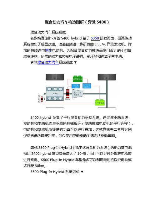
混合动力汽车构造图解(奔驰S400)混合动力汽车系统组成新款梅赛德斯-奔驰S400 hybrid基于S350研发而成,但其传动系统做出了明显改进。
改进包括进一步研发的3.5L V6汽油发动机、附加的持续通电同步电动机、为配合混合动力模块而专门设计的七挡自动变速箱、所需的动力和控制电子装置、变压器和锂离子蓄电池。
奔驰混合动力汽车系统组成▼S400 hybrid 配备了平行混合动力驱动系统。
通过该驱动系统,发动机和电动机均与驱动轮机械相连(发动机和电动机的平行连接)。
电动机和发动机所提供的功率可以进行叠加,这就意味着二者可分别保持更低的额定功率,但仅使用电动驱动系统无法驱动车辆。
奔驰S500 Plug-In Hybrid(插电式混合动力系统)的动力蓄电池相比S400 hybrid 车型容量增大了10倍,而且可以经过外部充电插座进行充电。
S500 Plug-In Hybrid车型最多可以利用电动机以纯电动模式行驶30km。
S500 Plug-In Hybrid系统组成▼1—湿式离合器(NAK);2—再生制动系统(RBS);724.2—自动变速箱;A9/5—电动制冷剂压缩机;A79/1—电动机;A100g1—高电压蓄电池;G1—车载电气系统蓄电池;M1—起动机;M276.8—发动机;M42—电动辅助油泵(集成在变速箱内);M56—真空泵(电动);N33/5—高电压正温度系数加热器;N68—电子动力转向控制单元;N82/2—蓄电池管理系统控制单元;N83/1—直流转换器控制单元;N83/5—充电装置;N129/1—功率电子装置控制单元;X58/23—充电装置供电插座混合动力汽车工作模式驱动模式▼混合动力驱动系统各种驱动模式的当前动力流可在驾驶室管理及数据系统(COMAND)显示单元上加以显示。
在驱动模式下,动力仅由发动机流向后轴。
加速模式▼在加速模式下,动力由发动机和电动机流向后轴。
高压蓄电池对电动机供电,然后由电动机产生驱动转矩,以对发动机所产生的转矩提供支持。
奔驰S400混合动力方案
Hybrid Concept inS 400 HYBRIDSystem DescriptionBild auf der Vorgabeseite in der Größe215x149 mm einfügenMercedes-Benz ServiceSystem DescriptionHybrid Concept in S 400 HYBRIDDaimler AG · Technical Information and Workshop Equipment (GSP/OI) · D-70546 StuttgartInformation and copyrightOrdering workshop informationAll printed workshop information from GSP/OI, such as Introduction intoService Manuals, System Descriptions, Function Descriptions, TechnologyGuides, Technical Data Manuals and adhesive labels, can be ordered asfollows:In GermanyFrom our GSP/OI shop on the InternetLink:http://gsp-ti-shop.deor alternativelyE-mail:customer.support@Telephone:+49-(0)1805/010-7979Fax:+49-(0)1805/010-7978Outside GermanyPlease get in touch with the contact person responsible for your market.Product portfolioComprehensive information about our full Product Portfoliocan also be found at our Internet Portal.Link:Questions and suggestionsIf you have any questions or suggestions concerning this product, please writeto us.E-mail:customer.support@Fax:+49-(0)1805/010-7978or alternativelyAddress:Daimler AGGSP/OISHPC R822, W002D-70546 Stuttgart© 2009 by Daimler AGThis document, including all its parts, is protected by copyright.Any further processing or use requires the previous written consent ofDaimler AG, Department GSP/OIS, HPC R822, W002, D-70546 Stuttgart.This applies in particular to reproduction, distribution, alteration, translation,microfilming and storage and/or processing in electronic systems, includingdatabases and online services.Image No. of title image:P00.00-4414-00Order No. of this publication:6516 1367 0204/2009Contents Preface 5OverviewIntroduction 6 Technical data 10 Block diagram 12 Display concept 14SubsystemsEngine 18 Electric motor 20 Automatic transmission 22 Electric refrigerant compressor 23 Power electronics module 24 DC/DC converter module 25 Power electronics and DC/DC converter cooling 26 High-voltage battery module 27 High-voltage battery cooling 28 Brake pedal assembly 30 RBS brake booster 31 Electric vacuum pump 32 Electrohydraulic power steering 33Operating strategyOverview 34 Driving mode 36 Torque coordination 40 Automatic engine stop 44 Automatic engine start 48 Energy management 52 Alternator interface 53System Description of Hybrid Concept in S 400 HYBRIDContentsDeceleration mode 54Regenerative braking 58Ignition ON/OFF 62Starting 63Monitoring/deactivation 64On-board electrical systemLocation of control units 66Networking of high-voltage/12 V on-boardelectrical systems 68Interlock 69Service informationDiagnosis 72Deenergization 73Working on the vehicle 74Requirements of service personnel 76Training 77Questions and answersQuestions about the hybrid drive 78AnnexAbbreviations 80Index 81Notes 82 System Description of Hybrid Concept in S 400 HYBRIDPrefaceSystem Description of Hybrid Concept in S 400 HYBRID Dear Reader,This system description presents the hybrid concept of the S 400 HYBRID from Mercedes-Benz.It allows you to familiarize yourself with the technical highlights of this new concept in advance of its market launch. This brochure primarily intended to provide information for people employed in service, mainte-nance and repair as well as for aftersales staff. It is assumed that the reader is already familiar with the Mercedes-Benz model series and major assemblies currently on the market.In terms of the contents, the emphasis in this system description is on presenting new and modified compo-nents, systems, system components and their func-tions.This system description aims to provide an overview of the technical innovations and an insight into the systems.However, this system description is not intended as a basis for repair work or technical diagnosis. For such needs, more extensive information is available in the Workshop Information System (WIS) and in the Diag-nosis Assistance System (DAS).These systems are updated on a monthly basis. There-fore, the information available there reflects the latest technical status of our vehicles.The contents of this brochure are not updated and no provision is made for supplements. We will publicize modifications and new features in the relevant WIS documents. The information presented in this system description may therefore differ from the more up-to-date information found in the WIS.All the information relating to specifications, equip-ment and options is valid as of the copy deadline in March 2009 and may therefore differ from the current production configuration.Daimler AGTechnical Information and Workshop Equipment (GSP/OI)IntroductionO v e r v i e wb System Description of Hybrid Concept in S 400 HYBRIDThe new Mercedes-Benz S 400 HYBRID is based on the S 350 but its drivetrain has undergone significant modification. The modifications include the further developed 3.5-liter V6 gasoline engine, the additional permanently energized synchronous motor, the 7-speed automatic transmission (7G-TRONIC) which has been specially designed to accommodate the hybrid module, the required power and control elec-tronics, the voltage converter and the lithium-ion battery.The compact hybrid module consists of a disk-shaped electric motor, which also serves as a starter and high-voltage alternator. The system has two advantages: on the one hand, it helps to save fuel and, on the other, it increases driving pleasure. One reason for this is the "boost effect", whereby the electric motor powerfully supports the combustion engine in the high-consump-tion acceleration phase. The driver benefits from the interaction of the two major assemblies in the form of an even more impressive torque curve and superior power development every time the vehicle starts off or accelerates.The hybrid module is also equipped with a convenient start-stop function which shuts off the engine when the vehicle is stopped e.g. at traffic lights. When it is time to drive on, the electric motor starts the combus-tion engine almost unnoticeably and very comfortably. This also makes a contribution to fuel economy and protecting the environment because the engine starts almost immediately with the first ignition. This means that the emissions are also minimized during the start-up phase.When the vehicle decelerates, the electric motor oper-ates as a high-voltage alternator and is able to recover braking energy through the "regenerative braking" process. In doing so, the electric motor works harmo-niously to support the engine braking effect of the combustion engine and the conventional wheel brakes in a seamless series of steps. The recovered energy is stored in a high-performance compact lithium-ion battery for later usage as required. The "major assembly coordinator" integrated in the engine control unit is responsible for managing the hybrid drive system with its energy management and torque coordination modules.i Why a hybrid?The automobiles of the future will be increasingly influenced by the following factors:•Limited natural resources•Long-term rises in energy prices•Legal stipulations on environmental compati-bility and CO 2 emissions•Changes in purchasing behavior in favor of more environmentally friendly and economical vehiclesi NoteOnly trained workshop staff (electrical technician for high-voltage on-board electrical systems in motor vehicles) may carry out work on a high-voltage on-board electrical system.IntroductionO v e r v i e wSystem Description of Hybrid Concept in S 400 HYBRID The S 400 HYBRID is equipped with a parallel hybrid drive. With this drive system, both the combustion engine and the electric motor are mechanicallyconnected to the drive wheels (parallel connection of engine and motor).The power supplied by the electric motor and the engine can be added together, which means that the individual power ratings of both can be kept lower. It is not possible to drive the vehicle solely using theelectric drive system.Overview of drive concept 112V alternator2Internal combustion engine 3Electric motor47-speed automatic transmission (7G-TRONIC)5Power electronics module 6High-voltage battery module 7DC/DCconvertermodule 812 V batteryIntroductionO v e r v i e wb System Description of Hybrid Concept in S 400 HYBRIDView of vehicle from right frontDesignationMarket launchModel designation W 221/V 221Engine TransmissionS 400 HYBRIDECE 06/2009Japan 08/2009 USA 09/2009China 09/2009221.095/221.195272.974722.950IntroductionO v e r v i e wOverview of hybrid components 1High-voltage battery module 2DC/DCconvertermodule 3Power electronics module 4Electric motor 5Pedal assembly 6RBS brake booster7Electric vacuum pump8Electric refrigerant compressor 9Low temperature cooler10Low-temperature circuit circulation pump 11Electrohydraulic power steering12Hydraulic unit with regenerative braking system control unitTechnical dataO v e r v i e wUnitS 400 HYBRIDCombustion engine Rated output at engine speed kW (hp)rpm 205 (279)6,000Rated torque at engine speed Nm rpm 3502,400 – 5,000No. of cylinders —6Displacement cm 33,498Max. rpm rpm 6,500Compression ratio —10.7:1Valves per cylinder —4Mixture formation—Microprocessor-controlled gasoline injectionwith hot film mass air flow sensorPower transmission Drive—Rear wheel drive Automatic transmission —7G-TronicElectric motor Type Permanently energized synchronous motorRated output kW (hp)15 (20)Rated torque at engine speed Nm rpm 1601,000Max. starting torque Nm 215Rated voltageVolts126Technical dataO v e r v i e wUnitS 400 HYBRIDHigh-voltage battery Type Lithium-ion battery Rated voltage V 126 (35 cells x 3.6V)Capacity Ah 7Weightkgapprox. 28Combustion engine and hybrid module combined Rated output at engine speed kW (hp)rpm 220 (299)6,000Rated torque at engine speed Nm rpm3852,400 – 4,000Performance Maximum speed km/h 250Accelerationfrom 0 to 100 km/h s 7.2Fuel consumption 1l/100 km 7.9CO 2 emissions 1g/km186Weight penalty of hybrid components Electric motor kg 20High-voltage battery kg 28Power electronics 2kg 8DC/DC converter 2kg3.21As per NEDC cycle2 Without wiring harnessTechnical dataO v e r v i e wA1Instrument cluster A1p13Multifunction displayA9/5Electric refrigerant compressor A40/3COMAND controller unit A79Electric motorA89DTR controller unit (with DISTRONIC PLUS or adaptive cruise control)A91/1Electrohydraulic power steeringA100b2High-voltage battery cell temperature sensors A100g1High-voltage battery A100s1Protection switch A101Tank leak diagnostic moduleB10/13Low-temperature circuit temperature sensor B37Accelerator pedal sensor CAN BInterior CAN CAN C Drivetrain CAN CAN D Diagnostic CAN CAN E Chassis CAN CAN F Central CANCAN H Vehicle dynamics CAN CAN I Drivetrain sensor CAN K88Pyrotechnical separatorK108Circulation pump relay 1 (power electronics)K108/1Circulation pump relay 2 (power electronics)L6/1Left front rpm sensor L6/2Right front rpm sensor L6/3Left rear rpm sensor L6/4Right rear rpm sensorTechnical dataO v e r v i e wM13/8Circulation pump 1 (power electronics)M3Fuel pumpM13/9Circulation pump 2 (power electronics)M42Additional electric transmission oil pump N2/7Restraint systems control unit N3/10ME-SFI [ME] control unitN10/1Front SAM control unit with fuse and relay moduleN22/1AAC [KLA] control unitN30/6Regenerative braking system (RBS) control unit N62/1Radar sensors control unit (SGR)(with DISTRONIC PLUS or adaptive cruise control)N73EZS control unitN82/2 Battery management system control unit (BMS)N83/1 DC/DC converter control unit N89 Additional transmission oil pump control unit N93Central gateway control unit N118Fuel pump control unitN129/1Power electronics control unit S9/3Hybrid brake light switchS62/51Hybrid engine hood contact switch X11/4Data link connector Y3/8Electric controller unit (VGS)Y130Engine oil pump valveDisplay conceptO v e r v i e wThe current power flows of the various driving modes of the hybrid drive can be displayed on the display unit of the COMAND system.In driving mode , power flows only from the combus-tion engine to the rear axle.In acceleration mode , power flows from the combus-tion engine and from the electric motor to the rear axle. The high-voltage battery supplies power to the electric motor, which then generates drive torque to support the torque produced by the combustionengine.Acceleration modeDriving modeDisplay conceptO v e r v i e wIn alternator mode , power flows from the rear axle to the electric motor. The kinetic energy of the vehicle is converted into electrical energy by the electric motor. The electric motor acts as a high-voltage alternator and charges the high-voltage battery.Alternator modeDisplay conceptO v e r v i e wA consumption bar chart shows the fuel consumption and the electrical energy generated.Display of fuel consumption and energy balanceA Fuel consumption over last 15 minB Display of energy recovered by high-voltage battery in last 15 minDisplay conceptO v e r v i e wThe energy flows during the various operating modes and the current charge level of the high-voltage battery can also be displayed on the instrument cluster.The message "READY" is output as soon as the hybrid drive system is operational.When the ECO start-stop function is available, the green READY indicator lights up.When the ECO start-stop function is temporarilyunavailable, the yellow READY indicator lights up.i Charge indicatorThe charge level of the high-voltage battery shown on the instrument cluster and COMAND system is an adjusted figure which only represents the battery capacity which is actually available. The actual charge level of the high-voltage battery in terms of the SOC (State of Charge) can be read out via the Diagnosis Assistance System (DAS).Instrument cluster displaysEngineS u b s y s t e m sEngine 272.974 has been modified and optimized for the hybrid drive. The output has been increased by 5kW through the use of new cylinder heads, modified camshafts with a different camshaft control system and different pistons.The use of the Atkinson principle increases thethermal efficiency and lowers specific fuel consump-tion. This improves consumption under partial-load conditions.The rotor of the electric motor is connected directly to the crankshaft and positioned between the engine andautomatic transmission.View of engine from right rear 1Electrical plug connection 2UVW screw connection A79Electric motorL20Rotor position sensori NoteThe Atkinson principle optimizes the valve timing by briefly opening the intake valves between the intake and compression phase. This makes the expansion phase longer than the compression phase.EngineS u b s y s t e m sPerformance graph A Combustion engine output B Maximum combined output(electric motor and combustion engine)CMaximum boost outputTorque diagramA Combustion engine torqueB Maximum combined torque(electric motor and combustion engine)C Maximum boost torqueElectric motorS u b s y s t e m sThe disk-shaped electric motor is a permanently ener-gized synchronous motor which is installed between the combustion engine and automatic transmission. It performs the function of a starter and high-voltage alternator. This design is also referred to as an inte-grated starter-alternator.The electric motor acts as a damping element to reduce drive/torsional vibrations. Depending on the operating mode, the electric motor can apply torque in the direction of rotation of the crankshaft in order to start the combustion engine (drive mode ) or apply torque in the opposite direction to the rotation of the crankshaft in order to charge the high-voltage battery (alternator mode ). During start-off, the electric motor supports the combustion engine (boost mode) and, during brake application, part of the braking energy is converted into electrical energy (regenerative braking).Switching between the individual operating modes (motor mode/alternator mode) is controlled by the power electronics control unit. The power electronics are connected to the three power connections of the electric motor by three busbars. The three-phase currents are regulated depending on the operating mode and rotor position. These phase currents generate a magnetic field which, together with the field of the rotor, generates torque to produce rota-tional movement.Sectional view 1Stator carrier2Rotor with increment ring and position sensor track 3Intermediatehousing 4Stator with coils5Electric screw connection and temperature sensor couplingL20Rotor position sensorElectric motorS u b s y s t e m sInformation about the current rotor position isrequired in order to regulate the electric motor. For this purpose, the rotor position sensor supplies an amplitude signal even when the electric motor is stationary and forwards this to the power electronics control unit so that angle can be calculated and the rotational speed derived from this. A temperature sensor integrated in the stator winding records the temperature of the winding and transmits this to the power electronics control unit as a voltage signal. If a certain temperature threshold is exceeded, appropriate power limitation functions are activated in the power electronics in order to protect the electricmotor from overheating.Exploded view 1Stator with coils1/1Electric screw connection and temperature sensor coupling 2Stator carrier3Rotor with increment ring and position sensor track 4Intermediatehousing B70Crankshaft Hall sensor L20Rotor position sensorAutomatic transmissionS u b s y s t e m sThe S 400 HYBRID is equipped with a 7-speed auto-matic transmission (7G-TRONIC). The transmission has been modified for the hybrid drive system. Along with new software for transmission control, an addi-tional electric transmission oil pump is also installed.It is necessary to ensure that oil continues to be supplied to the transmission hydraulics when the engine is off or being restarted as part of the start-stop function in order to prevent any delay between the driver's request to start off and the point when the vehicle actually starts to move.For this reason, the additional electric transmission oil pump supplies oil for the transmission control system when the internal transmission oil pump is shut off because the combustion engine has also beenswitched off.Sectional view of automatic transmission 1Carrierring2Internal transmission oil pump3Additional electric transmission oil pump (M42)Electric refrigerant compressorS u b s y s t e m sIn order to provide adequate cooling output even when the engine has been automatically stopped, the drive system for the refrigerant compressor has to be separated from the combustion engine to provide independent climate control for the vehicle interior and independent cooling for the high-voltage battery. This is achieved by means of an electrically driven refrigerant compressor. This cooling system only operates as required and thus also helps to optimize fuel consumption.The electric refrigerant compressor draws in and compresses the refrigerant (R134a) and pumps the refrigerant through the system. Depending on the evaporator temperature, the electric refrigerant compressor is steplessly regulated by the AAC [KLA] control unit from 800 to 9,000 rpm.The electric refrigerant compressor consists of the following three main groups:•Control unit with integrated power electronics (1)•Electric motor (2)•Spiral compressor (3)The control unit of the electric refrigerant compressor regulates the speed of the electric motor and the quantity of refrigerant. The electric motor drives the spiral compressor. This consists of two spiral coils nested inside each other, whereby the first coil is permanently attached to the housing and the second moves in a circular pattern inside the first. The spiral coils thus touch each other at several points and form a number of chambers of ever decreasing size within the coils. The refrigerant is thus compressed and moves towards the center of these chambers, whereit then exits the spiral in compressed form.View of refrigerant compressor 1Control unit 2Electric motor 3SpiralcompressorPower electronics moduleS u b s y s t e m sThe power electronics control unit is integrated in the power electronics module. This is positioned on the right underneath the exhaust manifold. It is fitted with a heat shield to protect it against thermal radiation.The power electronics control unit supplies the elec-tric motor with three-phase AC voltage upon request. It monitors the temperature of the electric motor as well as performing diagnosis and providing forecastsof the available torque to the ME-SFI [ME] control unit.Design of power electronics module 1Power electronics module212 V plug connection for power electronics control unit 3High-voltage line to high-voltage batteryA Coolant inlet BCoolantoutletDC/DC converter moduleS u b s y s t e m sThe DC voltage converter (DC/DC converter) is located in the right front wheel well. It generates a high DC voltage and a 12 V DC voltage and also allows the exchange of energy between the high-voltage on-board electrical system and the 12 V on-board elec-trical system. High-voltage is converted into 12 V orvice versa.Design of DC/DC converter module 1DC/DC convertermodule2High-voltage plug connection (high-voltage battery)312 V plug connection for DC/DC converter control unit 4Circuit 30 screw connection A Coolant inlet BCoolantoutleti NoteSince battery energy is exchanged between the 12V on-board electrical system and the high-voltage on-board electrical system, it is possible to jump start the vehicle with a 12V jumper cable with the ignition switched on. In other words, a separate high-voltage charger is not required to start the vehicle if the battery has been discharged.Power electronics and DC/DC converter coolingS u b s y s t e m sThe power electronics module and the DC/DC converter module have a common low-temperaturecooling system which is separate from the coolingsystem of the combustion engine. This low-tempera-ture cooling system protects the power electronics module and the DC/DC converter module fromdamage due to overheating. The ME-SFI [ME] control unit records the coolant temperature in the power electronics cooling system by means of the voltage signal from the low-temperature circuit temperature sensor.Depending on the coolant temperature, the ME-SFI [ME] control unit actuates circulation pump relay 1 and circulation pump 1 is switched on. Circulation pump 2 is switched on via circulation pump relay 2. Circulation pump relay 2 is actuated by circuit 15 when the ignition is switched on.The coolant flows through the DC/DC converter module and the power electronics module andabsorbs thermal energy from these components. The coolant then flows through the low-temperature cooler, where it is cooled by the airstream and flowsback to circulation pump 1.Schematic illustration of power electronics cooling circuit 1Expansion tank2Low-temperature cooler 3Power electronics module 4DC/DC converter moduleB10/13Low-temperature circuit temperature sensor M13/8Circulation pump 1M13/9Circulation pump 2AFeed to low-temperature cooler, coolant temperature very high B High coolant temperature C Medium coolant temperature D Return from low-temperature cooler,coolant temperature lowHigh-voltage battery moduleS u b s y s t e m sThe high-voltage battery module is located at the rear of the engine compartment on the right. It protects the high-voltage battery from external heat and provides physical stability. The high-voltage battery module incorporates the high-voltage battery, the battery management system (BMS) control unit and theprotection switch. Refrigerant lines and electrical lines (high-voltage/12 V) can be connected to the high-voltage battery module. The high-voltage battery is a lithium-ion battery, which stores energy for the elec-tric motor.The advantages compared to nickel metal hydride batteries are:•Greater electrical efficiency•Higher energy density and thus lower weight and more compact dimensions The high-voltage battery is connected to the 12 V on-board electrical system via the DC/DC converter so that it can provide support to the 12 V on-board elec-trical system if necessary. The protection switch is actuated by the battery management system (BMS) control unit and internally isolates the high-voltage battery positive and negative terminals from the high-voltage on-board electrical system.Sectional view of high-voltage battery module 112 V plug connection for battery management system control unit2Refrigerant line connections3High-voltage plug connection (power electronics, electric refrigerant compressor)4High-voltage plug connection (DC/DC converter)5Protection switch6Blow-off fitting with membrane and bursting diskA100 High-voltage battery module A100g1High-voltage batteryN82/2Battery management system (BMS) control unitHigh-voltage battery coolingS u b s y s t e m sThe operating temperature of the high-voltage battery must be within a certain range in order to ensure that the charging capacity, number of charging cycles and life expectancy of the high-voltage battery are opti-mized.The battery management system (BMS) control unit evaluates the data from the high-voltage battery cell temperature sensors in order to determine the current high-voltage battery temperature and, if necessary, requests cooling output via the ME-SFI [ME] control unit. The battery management system (BMS) control unit sends the request for cooling to the ME-SFI [ME] control unit via the drive train sensor CAN. This compares the request against the targets of the energy management system and allows actuation of the electric refrigerant compressor.Electric refrigerant compressor actuation is allowed depending on the charge level of the high-voltage battery and the maximum tolerable dischargevoltages/currents. Actuation is first allowed after the vehicle is started with the key and this permission is withdrawn when circuit 15 is switched off.If the energy management system allows actuation, this information is transmitted by the ME-SFI [ME] control unit to the central gateway control unit via the chassis CAN together with the request for cooling output. This approval is forwarded to the AAC [KLA] control unit on the interior CAN, which actuates the electric refrigerant compressor via the CAN network.The air conditioning shutoff valve is opened and the refrigerant flows through the evaporator integrated in the high-voltage battery module. Thermal energy is extracted from the high-voltage battery and battery management system (BMS) control unit.The cooling output is largely dependent on the actua-tion level of the electric refrigerant compressor. When the engine is idling or has been stopped automatically, the output of the electric refrigerant compressor is limited to a maximum of 2kW.The output of the electric refrigerant compressor can also be temporarily (<10 s) reduced right down to 0kW if rapid acceleration is required.。
奔驰S500Hybrid混合动力汽车技术特点

奔驰S500Hybrid混合动力汽车技术特点陈鸣洲;夏征;付贻玮;宋建桐【摘要】S500Hybrid是奔驰首款插电式混合动力汽车,它体现了奔驰未来在插电式混合动力汽车的特点,文章介绍了奔驰S500Hybrid的自动启动和自动停止,以及混合动力系统工作模式.【期刊名称】《汽车实用技术》【年(卷),期】2017(000)001【总页数】2页(P1-2)【关键词】奔驰;混合动力;电驱动【作者】陈鸣洲;夏征;付贻玮;宋建桐【作者单位】北京电子科技职业学院汽车工程学院,北京100176;中油管道检测技术有限责任公司,河北廊坊065000;北京电子科技职业学院汽车工程学院,北京100176;北京电子科技职业学院汽车工程学院,北京100176【正文语种】中文【中图分类】U464.1CLC NO: U464.1 Document Code: A Article ID: 1671-7988 (2017)01-01-02 随着传统燃料的不断消耗,新能源汽车的发展已经是世界各个国家、汽车企业都要面对新的难题、挑战及机遇[1,2]。
目前大部分的汽车企业都陆续推出了自己的混合动力汽车,奔驰作为百年的高档汽车品牌之一,在推出S300、S400等弱混合动力汽车之后,推出了奔驰S500Hybrid插电式混合动力汽车。
对于奔驰来说,这是真正意义上的首款新能源汽车,从电动辅助提速转变为了电动驱动,其具有大容量的高压蓄电池和充电借口。
由于S500Hybrid应用了插电式混合动力驱动技术,混合动力车辆装配了高压系统电压为140V。
发动机电控燃油喷射系统和点火系统的能源管理模块将高压转变为12V电压。
因此,电控燃油喷射系统和点火系统要通过传动系统局域网与发电机进行通信。
当发动机关闭时,12V电仍由高压蓄电池供电,当发动机运转时,有电机供电。
如果电力电子控制单元提供的能量无法满足现有能量要求,则发电机将开启。
在传动系统控制单元中有一个能源管理模块,它负责协调混合动力系统的能量传输,并根据电气因素创建蓄电池管理系统控制单元、电力电子控制单元和电动制冷剂压缩机的接口,为此通过CAN网络与所有相关控制单元传送信息。
新车:奔驰新S极
新车:奔驰新S极作者:黄帅来源:《汽车博览》2013年第06期作为奔驰的旗舰车型,新一代S级集中呈现了奔驰品牌追求完美的造车理念,同时也将整个汽车产业对豪华汽车的认识推向了新的高度。
在新一代S级的制造商奔驰看来:“S级是世界上最好的汽车”。
面对这款刚刚发布的汽车,我们既不会简单地认同这一观点,也不想直截了当地予以否定。
因为面对每一款汽车,无论是达契亚Lodgy,还是兰博基尼盖拉多,都须经历紧急制动测试、动态操控测试、实用性测试以及超过2000公里的油耗测试之后,我们才会给出定义。
当然,凭借ams团队已经看到、了解到的信息,我们可以暂时给出这样的评价:已经发展到第6代的奔驰S级在车身尺寸方面继续、有节制地增长,而在设计、定位方面,新S级的目标似乎并不是简单地超越前代,它的很多细节意在向迈巴赫靠拢。
与此同时,为了满足中国及美国消费者的使用需要,奔驰在研发初期就优先照顾了长轴距款车型。
相比上一代车型,短轴款S级的车身长度由原来的5.10米增长到了5.12米;长轴距款同样如此,其车身长度由5.23米增长到了5.25米。
之所以保持相对克制的水平,或许是因为:长轴距款S并非奔驰的终极目标,在它之上,奔驰还将推出一款XL号S级。
凭借大约5.40米的车身长度,XL号S级的车内空间已经逼近之前的入门款迈巴赫。
除此之外,奔驰还将基于S级推出车身造型更为饱满流畅的大型双门轿跑车CL。
与此同时,砍掉车顶的CL还将与来自英伦的大型敞篷跑车一争高下。
伴随车身尺寸的增长以及舒适性配置的增加,降低油耗成为奔驰研发团队的首要难题。
对此,奔驰又一次将空气动力学设计锁定为降低油耗的突破口。
单就这一点而言,S级或许已经满足了“世界上最好的汽车”的要求。
相比风阻系数为0.27的上一代车型,奔驰将普通S级的风阻系数降低到了0.24,S 300 Bluetec Hybrid的风阻系数甚至达到了0.23的水平。
而同时代的A8、7系的风阻系数分别为0.27及0.28。
奔驰48V轻混系统技术特点及典型故障两例(下)
44-CHINA ·May点评(接上期)故障现象一辆2021款奔驰S400L,搭载256 930型发动机,VIN 码为W1K2231591A00****,行驶里程为15 478km。
车主反映,该车停放数小时后,再次启动时车辆无反应,且仪表台上出现48V蓄电池故障的标识。
故障诊断与排除该车装配带集成式启动发电机的6缸火花点火型发动机M256 (ISG1),排量为3.0L,输出功率为270+16kW,发动机通过涡轮增压器进行增压。
第 1 代集成式启动发电机 (ISA) 可通过助力,在短时间内产生额外的16kW输出功率。
在超速运转模式下,超过80%的蓄电池能量可返回蓄电池中(能量回收)。
带集成式启动发电机 (ISA) 的48V车载电气系统还可启用其他功能,如预进入智能气候控制或无声启动(即几乎察觉不到发动机启动)。
另外,集成式启动发电机(ISA)还可调节怠速状态。
超速运转模式中,发动机可能会完全关闭,也可配合使用 DISTRONIC 主动式车距辅助系统。
M256发动机集成了48V电气化(轻混)系统,属于P1混动结构,带智能启动发电机的车载电气系统。
该系统包含一个直接安装在曲轴上的集成式启动发电机ISG(Integrated Starter Generator)。
P1混动系统的结构如图13所示。
奔驰48V轻混系统2021款奔驰S400L发动机无法启动Copyright 博看网 . All Rights Reserved.452022/05·汽车维修与保养此款发动机首次应用在车型 222(S级轿车)的改款车型中,开发时已将48V车载电气系统考虑在内,因此,省去了皮带驱动,这也成为了奔驰首款没有传动皮带的发动机。
12V发电机和12V启动机被集成式启动发电机(ISA)所取代,ISA位于内燃机和变速器之间。
除了具有发电机的功能外,也可使用来自48V车载电网蓄电池的能量生成扭矩以辅助内燃机,ISG和48V车载电网蓄电池的高输出功率,可让驾驶者几乎无法感知发动机的启动。
奔驰s400hybrid混合动力故障检测

奔驰s400hybrid混合动⼒故障检测奔驰s400hybrid混合动⼒故障检测摘要随着现今社会能源⽇益紧张、空⽓⽇渐污浊的情况下,⼈们越来越注重⾃⼰⽣活的环境质量好坏,⽽混合动⼒汽车⼀种节能,低碳排放的交通⼯具,因此在不久将来其⼀定会成为消费者热衷的车型,然⽽由于混合动⼒汽车的复杂程度较传统汽车相⽐有较⼤的难度,因此其检测维修也对维修⼈员提出较⾼要求,本⽂对混合动⼒汽车的检测与维修进⾏了简单的概述,并对奔驰s400hybrid车型的检测与维修⽅法进⾏简单的介绍。
关键词:驰s400hybrid;混合动⼒汽车;检测;维修⽬录1.引⾔ (3)2 混合动⼒汽车概述 (4)2.1 混合动⼒汽车概念 (4)2.2 混合动⼒汽车的特点 (4)2.3 混合动⼒汽车的分类 (5)3 混合动⼒汽车故障诊断概述 (6)3.1 汽车故障诊断的定义 (6)3.2 汽车故障诊断的⽅法及特点 (6)4 混合动⼒汽车各动⼒元件的故障诊断 (7)4.1 发动机的故障诊断 (7)4.1.1 发动机故障诊断技术的应⽤ (7)4.1.2 发动机的故障分类和分析 (8)5.奔驰s400hybrid混合动⼒汽车故障的检测 (9)5.1奔驰s400hybrid混合动⼒汽车检测维修需注意的事项 (10)5.2 奔驰s400hybrid混合动⼒汽车动⼒控制系统检测与维修 (10)5.3 奔驰s400hybrid混合动⼒汽车电池系统的检修 (10)6.结语 (11)参考⽂献 (12)1.引⾔汽车故障诊断与检测技术是随着汽车的发展从⽆到有逐渐发展起来的⼀门技术。
国外的⼀些发达国家,早在 20 世纪 40~50年代就发展成为以故障诊断和性能调试为主的单项检测技术。
进⼊ 60 年代后,故障诊断与检测技术获得较⼤的发展,逐渐将单项检测技术联线建站(出现汽车检测站),演变成为既能进⾏维修诊断,⼜能进⾏安全环保检测的综合检测技术。
随着电⼦技术的发展, 70 年代出现了检测控制⾃动化、数据采集⾃动化、数据处理⾃动化、检测结果⾃动打印的现代故障检测技术,检测效率极⾼。
梅赛德斯-奔驰S级轿车车书S-Class

传奇之路,再度启程自问世以来,梅赛德斯—奔驰汽车始终向世人展现着豪华轿车的精髓,并为众多极具品位且追求卓越的爱车人士带来了无限激情。
S级轿车的辉煌历史始于1951年——搭载6缸发动机的梅赛德斯—奔驰220车型,在首届法兰克福国际车展上耀世登场。
该车型虽然是首次亮相,但凭借其高水准的配备和优异的性能,很快赢得了公众的瞩目。
1972年,第一款S级车型(W116)面世,这是豪华轿车市场上极具代表性的梅赛德斯—奔驰正式车型。
卓越的舒适性、创新的技术以及全面的安全性是豪华轿车长久以来的标志性特征。
溃缩区、防抱死制动系统(A B S)、气囊以及电控稳定程式(E S P®)——这些汽车发展史上前所未有的创新技术,被成功地首先应用于S级轿车之上,并且早在其它车型相继采用之前就已深入人心,成为汽车发展史上的里程碑。
概览7动力|经典性能与强劲加速的完美融合S级轿车在不动声色间,就已展现了强劲的动力,带来真正的震撼感受,这也将成为未来汽车产业的标准。
降低S级轿车的燃油消耗量和二氧化碳排放量,开发智能混合动力发动机绝不只是一种理想,现在我们已经将其变为现实。
优雅|让每条道路都熠熠生辉每段路程都不尽相同,时而宽阔、平坦、独特,时而崎岖、偏僻、狭窄。
若想始终以轻松的心态,品味旅途中的舒适惬意,S级轿车就是您绝佳的选择。
概述9概述11沉静|全身心的放松均匀的呼吸、平稳的脉搏和清晰的思维是镇静沉着的驾驶方式的内在表现。
当您驾驶时,包括上百个传感器和无数电子系统在内的外部辅助系统同时为您提供安全保障,避免种种风险。
概述13座椅|与舒适一路同行人类用两条腿学走路时,身体演化为完美的“步行机”。
而现代科技使直立行走的人类演变成惯于久坐的生物,这意味着如何使坐姿尽可能轻松自然变得更为重要。
例如,采用符合人体工程学的主动式座椅。
旅行|世界尽收眼底有人说,要想欣赏真正的美景,就要融入到自然之中。
曾经,人们还在依赖非机动化的出行装备。
系统描述 S 400 Hybrid中的混合动力方案 [型号221]_cn
![系统描述 S 400 Hybrid中的混合动力方案 [型号221]_cn](https://img.taocdn.com/s3/m/4314a94fa8956bec0975e3fe.png)
S 400 HYBRID 的混合动力概念系统说明6高压蓄电池模块7 DC/DC 转换器模块8 12 伏蓄电池HYBRID车辆的右前视图驱动模式加速模式发电机模式A 过去15 分钟的燃油消耗量B 高压蓄电池在过去15 分钟回收能量的显示电动机的转子与曲轴直接相连,并位于发动机与自动变速箱之间。
发动机右后视图电气插头连接2 UVW 螺纹连接A79 电动机L20 转子位置传感器B 最大综合扭矩(电动机和内燃机)C 最大升压扭矩C 最大升压输出功率5 电气螺纹连接和温度传感器连接器L20 转子位置传感器2 内部变速箱油泵3 辅助电动变速箱油泵(M42)1 控制单元2 电动机3 螺旋压缩机A 冷却液进口B 冷却液出口伏的直流电压,并实现高压车载电气系统与12 伏车载电气系统之间的12 伏电压之间可以双向转换。
转换器模块的设计高电压插头连接(高压蓄电池)转换器控制单元的12 伏插头连接4 电路30 的螺纹连接A 冷却液进口B 冷却液出口12 伏车载电气系统与高压车载电气系统之间会交换蓄电池能量,因此,在点火接通的情12 伏跨接电缆对车辆进行跨接起动。
换言之,如果蓄电池已经放电,则不需要电力电子和DC/DC 转换器冷却电力电子冷却回路的示意图1 膨胀水箱2 低温冷却器3 电力电子模块B10/13 低温回路温度传感器M13/8 循环泵1M13/9 循环泵2A 对低温冷却器供给,冷却液温度非常高B 冷却液温度较高C 冷却液温度适中D 自低温冷却器回流,冷却液温度较低电动制冷剂压缩机)4 高电压插头连接(DC/DC 转换器)5 保护开关A100 高压蓄电池模块A100g1 高压蓄电池N82/2 蓄电池管理系统(BMS)控制单元高压蓄电池冷却5 后排空调系统蒸发器(装配后排空调系统)B10/11 后排空调系统蒸发器温度传感器(装配后排空调系统)B12 制冷剂压力传感器Y19/1 高压蓄电池冷却切断阀Y67 后排空调系统制冷剂切断阀(装配后排空调系统)A 高压,气态B 高压,液态C 低压,液态D 低压,气态B37/1 踏板角度传感器S9/3 混合动力制动灯开关Y113 踏板阻力模拟器阀A7/7b1 RBS 膜片行程传感器A7/7b3 RBS 真空传感器S11 制动液指示开关2 真空出口连接3 电动机4 泵单元1 电气插头连接A91/1 电液动力转向机构t 时间v 车速–曲轴的动能作用在电动机转子上。
腾讯试驾奔驰S400 HYBRID
带头大哥腾讯试驾奔驰S400 HYBRID 2010年10月26日11:16腾讯汽车张洋我要评论(0)字号:T|T[导读]我们经常说“坐奔驰”,这个奔驰指的就是S级,只有你真正体会过S级以后你才会明白什么是真正的奔驰,那种沉稳、气质、舒适的完美结合就连其最有力的竞争对手都无法超越的。
[腾讯汽车试驾]如今是谁统领着豪华车市场的头把交椅,我敢肯定的说是奔驰,确切说是奔驰S级。
就这个人们称作“大奔”的车型拥有非同寻常的销量,它提供的不仅仅是舒适和外表更多的是一种内涵,它已经成为身份的象征。
腾讯试驾奔驰S级400 HYBRID腾讯试驾奔驰S400 HYBRID就连奔驰S级的对手都不得不承认的是奔驰S级在市场中的老大地位,销量似乎更可以证明这一切。
无论在什么场合,奔驰总是豪华车的代言词,也许还有其他豪华品牌,但市场最认同的无疑还是这个三叉星标志的德国牌子。
腾讯试驾奔驰S400 HYBRID在目前中国在售的奔驰当中有一款与众不同的车型那就是S400,它是目前德系豪华品牌轿车当中唯一能够买到的混合动力车型。
它的出现也打破了日系车垄断混合动力市场的局面,当然对于那些有钱人而言,是否能够认识到购买混合动力车型的重要性,这就是另外一回事了。
腾讯试驾奔驰S400 HYBRID腾讯试驾奔驰S400 HYBRID腾讯试驾奔驰S400 HYBRIDS400系列于去年上市,本次推出的隶属奔驰S级的第九代车型。
从2006年推出至今在经过去年的小改款之后,目前在国内销售车型包括S300、S350、S400 Hybrid 、S500、S600、S65 AMG等。
由于国内的奔驰S级均已经是加长版本,所以在轴距以及车长上均占有较为明显的优势。
目前来自中高级车型对于轴距长度的穷追猛打,有些让行政级轿车感到压力,不过行政级轿车拥有更加明显的优势。
腾讯试驾奔驰S400 HYBRID腾讯试驾奔驰S400 HYBRID腾讯试驾奔驰S400 HYBRID无论车头还是车尾,奔驰S级的造型都是经典的,不可复制的。
奔驰轿车Hybrid技术讲解

1.Hybrid是混合动力的意思,表示你看到的奔驰S400LHybrid 是油电混合动力车型Blue Efficiency(环保高效动力)2.BlueEFFICIENCY综合环保科技整合了包括优化引擎技术、降低车身重量、减小风阻、减小摩擦阻力等一系列旨在降低能量损耗、提升燃油效率的手段。
它所运用的CGI涡轮增压缸内直喷发动机更是在提高车辆动力性的同时,提升了燃油使用效率,从而降低油耗并减少二氧化碳排放量,达到了节油与环保的双重功效。
3.CGI:Stratified-Charged Gasoline Injection(缸内直喷系统),CGI 缸内直喷涡轮增压引擎它拥有着媲美柴油引擎的扭矩表现与燃油经济性,更保有汽油引擎高转速马力延展的优势4./bbs/viewthread.php?tid=12247740&extra=&page=1原帖由wizard于10-05-22 11:30 发表咨询两个E300的问题。
1.E300的C/S模式是不是就是换档时间的延迟?没任何别的区别?2.E300的DIRECT CONTROL底盘和C的敏捷悬挂有啥区别?1.E300 S为运动驾驶模式C为舒适,经济驾驶模式C模式优势在于换挡缓和,平稳性好,升档早低速不易打滑!S模式运动感好!换挡是否延时更具您急加油还是缓加油!缓加提前急加滞我试个先,为什么同排量的引擎,BMW的比奔驰的数据强?奔驰引擎刷ECU,什么情况下不影响原厂保修?奥迪,BMW几乎全系都厂GPS配置,北奔C在产3年了为什么还未开发安装GPS?国产北奔已在产多年,为什么维修 ...1.两种车设计风格不同,引擎属于汽车的动力源,奔驰设计相对而言保守,但奔驰现对于宝马而言高速加速性能很强。
数据相对来说还是的靠您自己实际去操控一下体检试驾!每个人都会对两款车又有不大一样的见解!个人见解2.在四S店里不可以,都会有影响!因为保修数据会发给中国奔驰保修部或北京奔驰保修部,能查出数据偏差。
我最喜欢的一辆车之技术介绍与分析

汽车电子论文我最喜欢的一辆车之技术介绍与分析【前言】近年来,随着电子技术,计算机技术和信息技术的应用,汽车电子控制技术得到了迅猛的发展,尤其在控制精度,控制范围,智能化和网络化等多方面有了较大突破.汽车电子控制技术已成为衡量现代汽车发展水平的重要标志. 汽车电子控制系统基本由传感器,电子控制器(ECU) ,驱动器和控制程序软件等部分组成,与车上的机械系统配合使用(通常与动力系统,底盘系统和车身系统中的子系统融合) ,并利用电缆或无线电波互相传输讯息,即所谓的"机电整合",如电子燃油喷射系统,制动防抱死控制系统,防滑控制系统,电子控制悬架系统,电子控制自动变速器,电子助力转向等.汽车电子控制系统大体可分为四个部分:发动机电子控制系统,底盘综合控制系统,车身电子安全系统,信息通讯系统.其中,前两种系统与汽车的行驶性能有直接关系.【关键字】汽车电子系统变速器2009 年夏季投放市场的奔驰 S400 HYBRID 是梅赛德斯-奔驰的首款混合动力轿车,其搭载带有紧凑混合动力模块的增强型 3.5 L V6 汽油发动机。
该款车型的发动机可产生 205 kW 的输出功率,电动机可产生 15 kW 的功率和 160 N?m 的起动扭矩,这使得发动机实现了 220 kW 的综合功率和 385 N?m 的最大综合扭矩。
该车按照新欧洲行驶循环工况(NEDC)测量的综合燃油消耗量为 7.9 L/100 km,CO2 排放量仅为 186 g/km。
采用混合动力驱动技术使该车的动力性与环保性的矛盾得到化解,打破了只有小排量汽车才能实现环境保护的定论。
在此,将对该车的混合动力系统及主要技术亮点进行介绍。
一、混合动力驱动系统概述奔驰 S400 HYBRID 混合动力汽车是由电动机(集成起动机和发电机功能)作为发动机的辅助动力驱动汽车。
在起步和加速工况时,由于电动机的辅助,相比于相同排量的车辆,耗油量和 CO2 排放有所改善。
奔驰混合动力S400 Hybrid原厂培训手册

车型名称 W 221/V 221 221.095/221.195
发动机
变速箱
S 400 HYBRID
ECE 2009 年 6 月 日本 2009 年 8 月 美国 2009 年 9 月 中国 2009 年 9 月
272.974
722.950
8
b S 400 HYBRID 混合动力概念的系统说明
– 经许 许 录 术状态 –
加速模式
14
b S 400 HYBRID 混合动力概念的系统说明
12
b S 400 HYBRID 混合动力概念的系统说明
– 经许 许 录 术状态 –
M13/8 M3 M13/9 M42 N2/7 N3/10 N10/1 N22/1 N30/6 N62/1
循环泵 1 (电力电子) 燃油泵 循环泵 2 (电力电子) 辅助电动变速箱油泵 防护装置控制单元 ME-SFI [ME]控制单元 带保险丝和继电器模块的前侧 SAM 控制单元 KLA 控制单元 再生制动系统 (RBS)控制单元 雷达传感器控制单元 (SGR) (装配增强型限距控制系统或自动智能巡航 控制)
S 400 HYBRID 混合动力概念的系统说明 b
– 经许 许 录 术状态 –
13
概述
技术数据
概述
显示概念
混合动力驱动系统各种驱动模式的当前动力流可 在驾驶室管理及数据系统 (COMAND)显示单元 上加以显示。 在驱动模式下,动力仅由内燃机流向后轴。
驱动模式
在加速模式下,动力由内燃机和电动机流向后 轴。高压蓄电池对电动机供电,然后由电动机产 生驱动扭矩,以对内燃机所产生的扭矩提供支 持。
S 400 HYBRID (221)
Daimler AG, GSP/OI, HPC R 822, D-70546 Stuttgart
奔驰 S400 混合动力 电动汽车--高压电板块

高压蓄电池
蓄电池管理
绝缘监测
兆欧级绝缘电阻 为识别绝缘短路
直接接触 间接接触
高压电系统不在车辆上搭铁,避免触电。
对混合动力车辆进行作业步骤
维修时需要断开高压电的部件
断开电路的措施(< 1000 伏) 断开电路 紧急呼叫 急救 医疗检查、转运 诊断、送往医院 触摸带电的零件有致命的风险。 关闭、拔出插头或取出保险丝可立即断开电路。 如果无法立即执行这些措施: 使自已绝缘(如干燥的板、干燥的衣服、干燥 的厚报纸、干燥的塑料包)且不触摸任何物品。 请各位师傅: 使用非导电物品(如干燥的木板条)将伤者与 带电零件分开或者通过衣服将其拉开。 时刻谨记安全,有紧急救人的意识。 进行急救 将伤者移至恢复体位。 观察反应,检查是否有呼吸和脉搏。 根据受伤类型进行急救。 拨打紧急电话:120或999 打电话给救援服务或急救医生。 电击后必须进行医疗检查。
你想感受电压和电流吗?
方法1:去科技馆,用手触摸静电球。 方法2:将打火机的芯取出,电击自己 方法3:将电脑外置音箱接通,拿住正负极,调节音 量大小,因人而异。 (MBCL老师推荐,请三思而后行)
突发事件处理
紧急措施 在发生触电事故后,必须 采续应急措施。这些措施 是根据“救援链”制定的。 后续措施
1.它由35个电池组成,每个电池为3.6V 2.其容量是普通电池的4倍。 3.锂电池的工作温度在15℃--35 ℃,通过空 调系统对其冷却 4.重量:25kg 电压:140V 价格:150000
5.厂商:Continental(奔驰、宝马共同研究)
Storage存储: • 存储时必须定期检查充电量。 • 最佳的充电量是介于50%至80%之间。 • 每个月1%的电自放电是极其低的,但这很大程度上取决于温度。 • 锂离子可重复充电的蓄电池应每过3至4个月充一次电,以防止过量 放电。如果电压降至2伏特以下,可能会损坏电池单元 (2.9 - 3.6 伏)。 Advantages优点: • 功率密度/能量密度特别高 • 充电快/放电电流大 • 循环次数极高(超过5000次) • 使用寿命长 • 不存在记忆效应 Note注: • 如果车辆持续停放四周或曾经库存,应对车上安装的锂离子蓄电池充 电(启动和驱动车辆)。 Special features特点: • 重量大,价格高 • 使用液态有机电解液 • 高压蓄电池是一种有害材料 • 运输遵从UN 3480锂离子蓄电池、级别 9、PG II的规定。
奔驰S400混合动力系统驱动模式

奔驰S400混合动力系统驱动模式
在电动驱动模式下,S400混合动力系统使用电池供电,只使用电动
机进行驱动。
这种模式非常适合在市区行驶时,可以提供安静、零排放的
驾驶体验。
在电动驱动模式下,S400可以行驶一定的距离,取决于电池
的充电情况和驾驶方式。
在混合驱动模式下,S400混合动力系统同时使用发动机和电动机进
行驱动。
电动机主要用于提供额外的动力支持和辅助驱动,减少发动机的
负荷和油耗。
混合驱动模式非常适合在高速公路上行驶时,可以提供更高
的动力输出和更低的油耗。
在燃油驱动模式下,S400混合动力系统完全依靠发动机进行驱动。
这种模式适用于长距离行驶或需要更高动力输出的情况。
在燃油驱动模式下,S400混合动力系统可以提供非常强劲的动力输出和出色的加速性能。
除了以上几种驱动模式外,S400混合动力系统还配备了一些智能驾
驶辅助系统,例如能量回收系统和智能充电系统。
能量回收系统可以将制
动时所产生的能量转化为电能储存到电池中,从而提高整体燃油效率。
智
能充电系统可以根据用电需求和驾驶行为智能调整电池的充电和放电策略,以提供最佳的驾驶体验和燃油经济性。
总的来说,奔驰S400混合动力系统具有灵活多样的驱动模式,能够
根据驾驶需求和道路条件智能调整动力输出和能源利用方式,既能提供强
劲的驾驶力和出色的加速性能,又能够实现低油耗和环保驾驶。
这使得
S400成为一款先进的混合动力豪华轿车,并且为未来汽车的发展铺平了
道路。
S400高压电系统

• COMAND 显示屏
1 ABS/ESP 警告灯 2 制动警告灯 3 再生制动系统(RBS)警 告灯 4 HYBRID 系统的READY 指 示灯 5 多功能显示屏
1 内燃机 2 电动机 3 高电压蓄电池 4 高电压蓄电池的电量 5 能量流
在 COMAND 系统“Vehicle”(车 辆)菜单中选择“Hybrid”(混 合动力)子菜单。
•对S400 HYBRID进行维护、修理时的注意事项 1.必须获得高压电认证和S400 HYBRID高压电产品认证的人员方可对其 进行维护、 修理。 2.高压电元件的警告标志:
混合动力/S400 HYBRID
混合动力/S400 HYBRID •S400 HYBRID 简介 S400 HYBRID 作为梅赛德斯-奔驰首辆混合动力轿车,于2009年夏季发 布,是世界上首款实现量产的使用高能锂离子高压电池(120V直流 高压电池)的豪华车型。 该车的NEDC (New European Driving Cycle )综合油耗为7.9L/100km, 这使得S400HYBRID 成为全世界同等性能级别车型中CO2 排放量最 低的车型----仅为186克/公里。该车使用一台排量为3.5l,输出功率为 205kw/279hp的汽油发动机,结合一个输出功率为15kw/22hp的电动 机,最终该混合动力系统总输出功率220kw/299hp,最大扭矩 385Nm。 S400 HYBRID展现了豪华、性能、安全和兼顾环保的和谐统一,并反 驳了只有小型车才能兼顾环保的言论,梅赛德斯-奔驰车主从此无需 再担心必须选择小型车才能降低CO2和其它气体的排放量。
• *维修信息: • 对DC/DC转换器进行 拆装时,必须先将12V 电瓶正极断开。 • 拆装30号电路插头后, 必须对该接头进行密 封
奔驰S400混合动力系统介绍20

S 400 HYBRID
S400混合动力车型概述
S 400 HYBRID于2009年夏季开始投放 市场,是梅赛德斯-奔驰的首款混合动力驱 动轿车,也是全球配备火花点火发动机的 最经济的豪华型轿车,其发动机为带有紧 凑混合动力模块的增强型V6汽油发动机。
S400混合动力车型概述
S400混合动力系统部件概述
DC/DC 转换器模块 N83/1
3 DC/DC 转换器模块 N83/1 3/1 高电压插头连接 3/2 DC/DC 转换器控制单元的插头连接 4 电路 30 的螺纹连接 A 冷却液入口 B 冷却液回流
S400混合动力系统部件概述
• DC/DC 转换器模块位于右前轮罩的后部。 • DC/DC 转换器控制单元是一个双向直流变压器,
• 通过仪表多功能显示屏观察车载电源能量 储备状况:使用多功能方向盘上的 或 箭 头按钮选择里程菜单。使用多功能方向盘 上的 或 箭头按钮选择混合动力菜单。
混合动力系统电量显示功能
混合动力系统电量显示功能
• 通过COMAND系统“车辆”菜单中选择 “混合动力系统”子菜单观察车载电源能 量储备状况:
• DC/AC控制模块是高电压线束的部件,其中包括 高电压保险丝盒 F70和相关的高压导线。如果线 束中的其中一个部件发生故障,则必须更换所有 部件。
• DC/AC控制单元通过三相交流电压促动电动机 (A79)。
• 电力电子控制单元通过传动系统CAN I 与车辆的 控制器区域网络CAN相连,并与其它控制单元交 换数据。
S400混合动力车型概述
S 400 HYBRID展现了豪 华性、动力性能、安全性和 环境保护之间的和谐统一。
S400混合动力车型概述
奔驰S400 HYBRID混合动力轿车技术亮点解析

奔驰S400 HYBRID混合动力轿车技术亮点解析
高云;楚宜民
【期刊名称】《汽车与驾驶维修:维修版》
【年(卷),期】2010(000)001
【摘要】2009年夏季投放市场的奔驰S400 HYBRID是梅赛德斯-奔驰的首款混合动力轿车,其搭载带有紧凑混合动力模块的增强型3.5LV6汽油发动机。
该款车型的发动机可产生205kW的输出功率,电动机可产生15kW的功率和
160N·m的起动扭矩,这使得发动机实现了220kW的综合功率和385N·m的最大综合扭矩。
该车按照新欧洲行驶循环工况(NEDC)测量的综合燃油消耗量为7.9L/100km,CO2排放量仅为186g/km。
【总页数】3页(P27-29)
【作者】高云;楚宜民
【作者单位】无
【正文语种】中文
【中图分类】U469.11
【相关文献】
1.奔驰S400 HYBRID混合动力新技术剖析(三) [J], 梁德福
2.奔驰S400 HYBRID混合动力新技术剖析(二) [J], 梁德福
3.奔驰S400 HYBRID混合动力——新技术剖析(四) [J], 梁德福
4.豪华但不奢华梅赛德斯-奔驰新S400 Hybrid [J], 李耕
5.奔驰S400 HYBRID控制机理及诊断实例探究 [J], 吴君;陈开考;王森
因版权原因,仅展示原文概要,查看原文内容请购买。
HYBRID 以实用为导向的混合动力技术

HYBRID:以实用为导向的混合动力技术时间:2010-03-26 00:21出处:爱卡汽车【转载】(有1个网友参与评论)字号:小大作为“通往零排放之路”的第二个阶段,梅赛德斯-奔驰开发了以实用为导向的模块化混合动力系统,以进一步提升车辆动力系统在日常使用中的工作效率。
其标准部件能够根据性能和应用范围,提供众多的扩展方式:不同水平的混合动力模块、以及能够适应最大排量汽油机和柴油机的蓄电池。
与发动机一样,所有混合动力模块都兼容7G-TRONIC7速自动变速器。
而在此基础上,无论是弱混合动力,还是可以通过全电力运行的强混合动力,梅赛德斯-奔驰均力求完美。
插电式混合动力代表了混合动力技术发展的下一个阶段。
在插电式混合动力中,蓄电池可以通过普通家用插座进行充电,从而增加车辆在电力驱动下行驶的里程。
通过混合动力模块化系统,梅赛德斯-奔驰在环保技术、车辆行驶经济性、安全性和乘坐舒适性方面树立了行业新标准。
从2009年夏季开始,梅赛德斯-奔驰成为第一家提供混合动力轿车(S 400 HYBRID)的欧洲汽车制造商。
作为第一款应用最先进锂离子电池技术的量产型混合动力轿车,S 400 HYBRID被称为全球最节油的汽油发动机豪华轿车。
S 500插电式混合动力轿车展现了梅赛德斯-奔驰模块化混合动力系统的领先成就。
这款车在完全电动驱动的情况下可以行驶30公里,实现完全的零排放行驶,其标准油耗仅为3.2升/100公里,二氧化碳排放量仅为74克/公里。
在缔造出色的燃油经济性的同时,S 500插电式混合动力轿车亦秉承了传统S级轿车的顶级舒适性、安全性和优越的动力性能。
在V6汽油直喷发动机、混合动力模块、以及高压锂离子电池组的共同作用下,S 500插电式混合动力轿车从0-100公里/小时的加速时间仅为5.5秒。
S 500插电式混合动力轿车的创新性驱动系统将在下一代S级之中面市。
此外,在刚刚结束的日内瓦车展中,梅赛德斯-奔驰的首款柴油混合动力车E 300 BlueTEC HYBRID首度揭下神秘面纱。
- 1、下载文档前请自行甄别文档内容的完整性,平台不提供额外的编辑、内容补充、找答案等附加服务。
- 2、"仅部分预览"的文档,不可在线预览部分如存在完整性等问题,可反馈申请退款(可完整预览的文档不适用该条件!)。
- 3、如文档侵犯您的权益,请联系客服反馈,我们会尽快为您处理(人工客服工作时间:9:00-18:30)。
德系豪华油电混合动力-奔驰S400-Hybrid
德系豪华油电混合动力奔驰S400 Hybrid
第二次世界大战结束之后,长期处于战争状态的人们急于重建美好的生活,而很多生产武器的兵工厂也逐步转化为生产民用机械,一直作为德国军用车的梅赛德斯-奔驰也是如此,在保留四驱车优势的同时开发更豪华更舒适的高端轿车。
发展至今梅赛德斯-奔驰已经推出的是第九代,在全新改款后的九代S级推出了首款德系的油电混合动力车型-S400 Hybrid。
在了解它之前我们先来看看S级的进化史,从中网我们来看什么是传承……
1945年第二次世界大战结束之后,欧洲人忙于建设家园,改变自己的生活,大家工作非常积极,1951年便推出了第一款奔驰S级轿车,此时Ponton后轮眉设计已经出现,直至第九代上沿袭了这一经典。
人们对美好生活的向往,很快3年后就退出了第二代奔驰S级轿车,虽然平台同为W187,但是更多的豪华配置增加,同时四门设计也是首次出现。
1959年受美国车外形设计的影响,奔驰也推出了火箭式尾部的S级轿车,同时这一设计也提高了尾部安全性,此年奔驰提出了吸能区的理念。
四速自动变速器和空气悬挂在这一代S级上已经成为标配。
从第三代开始奔驰按照8年一换代的规律更新S级轿车。
1965年,欧洲人不喜欢美国人的张扬,内敛低调重新回到了S级的设计当中,第四代S 级轿车首次配备V8 6.3升发动机。
1971年第五代S级开始有了翻天覆地的变化,中网高度被压缩,创新性的双横臂式前悬挂以及零偏距转动和防俯冲装置首次成为标准配备,同时世界上首款配备ABS的汽车诞生。
1979年法兰克福车展
上,第六代S级轿车大放异彩,安全气囊成为当时S级最大的亮点,也是最早配备安全气囊的量产车。
时间直接跨入年代,1991年第七代奔驰S 级是我们最熟悉的一代,这一代开始奔驰不但重新规划了产品型号的名称,同时制动辅助系统BAS也开始投入应用,被国人称为“虎头奔”的七代S级赢得了非常大的亚洲市场,也推出了首款V12发动机,这款能够代表身份和地位的车型,在欧洲遭遇了冷水,欧洲人并不喜欢这大家伙,而是更希望S级能够内敛、运动。
于是第八代S级彻头彻尾的变了样,1998年第八代S级上市,而这一代S级在欧洲得到好评的同时,丢失了亚洲和北美市场的标杆。
应用了30多项创新技术成果,当之无愧的再次成为轿车设计的潮流引领者。
这些技术包括自动气缸关闭(在需要时将S 500的8缸发动机转变为4缸发动机),DISTRONIC限距控制系统以及2001年推出的、使梅赛德斯-奔驰进入汽车安全新纪元的
PRE-SAFE驾驶员及乘客预防性安全系统。
2005年之前,奔驰的设计师一直苦于如何将欧洲人喜欢的运动内敛,与亚洲和北美地区喜欢的地位感相融合,这一年第九代S级在这两者之前诞生了。
COMAND系统将车身科技于一身,一个鼠标键即可控制全车设备。
2009年,第一款德系的油电混合动力车型S400 Hybrid诞生了
2009款梅赛德斯-奔驰S级在国内一共推出了5款车型,S300、S350、S500、S600以及
S400Hybrid 混合动力。
售价从93万-259.8万不等。
其中最招人眼目的就是S400 hybrid混合动力车型。
小改款S级最大变化则是增加了日间行车灯,大灯总成有所调节,将示宽灯和转向灯融合为LED并安排在了同一位置,夜间行驶时双排的LED非常漂亮。
尾部设计没有大的改变依旧是迈巴赫的元素,只不过原来与车身同色的尾灯饰条消失了,一体的尾灯显得不那么精致,红色也觉得比较庸俗,如果换成樱桃红那就更美了。
油电混合动力车型如今已经不是什么新鲜玩意儿了,起步最早的日本厂商早已量产了油电混合动力车,而作为欧洲主流豪华车,如果翻版日本的混合动力技术显得有些够不上星辉的身份。
从PPT上看,奔驰S400 Hybrid 属于技术相对简单的轻度混合动力,这样肯定不行。
我们看到丰田以及其他品牌的油电混合动力车型,在电池上一直是个头疼的问题,镍氢电池体积大,重量沉,占据了很大的空间。
奔驰首次采用了与手机、游戏机相同的锂电电池,大小相当于两个铝制饭盒的大小。
而电动机动力来源则与变速箱融为一体,电磁线圈位于发动机和变速箱之间,便于吸收刹车能量和释放电能。
这样变尽可能小的改变车身构造,同时也降低了成本。
起初,车辆在滑行中,轻微刹车,这时四轮的刹车系统是不工作的,而是依靠电子线圈来减速,同时吸收刹车动能转化为电能储存在电池中,之后在深度刹车后,刹车片才会抱紧刹车盘进行常规刹车,同时车辆在低于10公里时速时会熄火至停车,当松开刹车后发动机会迅速启动,踩油门的同时电池会全力带动电动机设备输出最大扭矩来推动车辆。
除了熄火外,似乎这套系统与F1的KERS系统相同。
其实F1进入混合动力的时代比奔驰要早。
而汽油机方面,S400 hybrid采用的3.5L V6直喷发动机,这与S350的配置相同,不同的时它还附加了15KW、160Nm的电动机,使其在起步时可以达到4.0升发动机的效果,从而称作S400也不足为奇。
S级改款之后,另一项创新科技则是它的前排液晶屏幕,经常会有人抱怨,这么豪华的车,坐在前排副驾驶的人不能够享受5.1声道的影音效果,只能与司机闲聊天,因为前排屏幕在车辆形式状态下,处于安全是关闭视觉系统的。
而小改款S级的分屏显示改变了这一点,分屏显示并不是将屏幕分成两部分,则是在两个不同的角度看屏幕是完全不同的内容。
车辆行驶时,司机的视角只能看到导航或者行车电脑显示,而副驾驶则可以与后排乘员共享
影音,如图所示,司机角度看到的是行车电脑,副驾驶则在看大片。
这技术岂不更苦了司机了……
从本质上讲,轻度混合动力在节油方面效果并不是非常显著的,相比强度混合动力这只是基础,而如果将轻混配置在大排量车上的话,节油怎是显著的。
我相信对于科技永远都要走在别人前面的奔驰来说,S400 hybrid只是一个开端,证明奔驰已经打开了新动力的篇章,未来发展如何我们拭目以待。