同济大学土木工程本科毕业设计-框架结构设计翻译(译文)
土木工程毕业设计译文 原稿为Comparison of Seismic Performance of
汶川地震前后钢筋混凝土框架结构的抗震性能比较摘要:2008年发生在中国的汶川大地震导致了大量的人员伤亡和财产损失.对地震之前和现在的混凝土框架结构的脆弱点比较是为了从理论上减小未来的损失。
一种之前在地震中被损坏的典型钢筋混凝土框架结构通过非线性有限元发进行分析.用于这些钢筋混凝土框架结构的基于概率论的地震响应模型被建立起来用来对之前和现在的建筑物的安全等级进行评估。
从关于及时占有率,重大损失,和损毁预防等级的脆弱性曲线的比较和分析可以看出,相比地震之前的混凝土框架结构,现在的混凝土框架结构有更高的安全等级。
关键词:钢筋混凝土框架结构,地震安全性,脆弱性评估,汶川地震引言:发生在2008年的里氏7。
9级汶川大地震是中国在过去50年中发生的最具破坏力的地震之一。
根据中国国家地震局发布的汶川地震等级地图显示,其震中最大烈度高达10度。
这样强烈的地表运动带来的直接结果是大概23143000房屋被损毁,其中多达6525000倒塌,主要在断层带上。
很多钢筋混凝土框架结构的建筑都遭受了大面积的和严重的损坏.汶川地震之后,很多国内和国际的组织着手对这些震区的损毁建筑进行调查研究。
地震发生后,由广州建筑鉴定中心派出的观测队被派往震中地区调查这些土木建筑表现的一手资料。
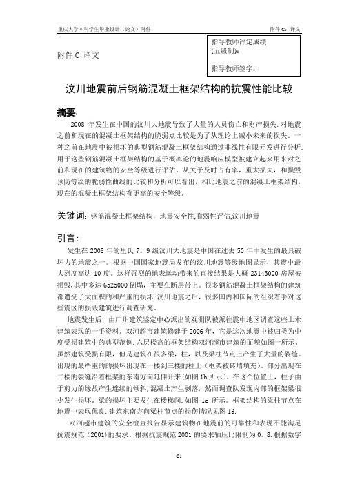
双河超市建筑修建于2006年,它是这次地震中被归类为中度受损建筑中的典型范例.六层楼高的框架结构双河超市建筑的面貌如图一所示。
虽然建筑受损有限,但是建筑在很多梁,柱,以及梁柱节点上产生了大量的裂缝。
出现的最严重的的损坏出现在一楼到三楼的柱上(框架被砖墙填充)。
部分出现在二楼的裂缝沿着框架的东南方向延伸开来(如图1b所示)。
在这个位置上,柱子由于剪力的缘故产生连续的倾斜,混凝土产生剥落,然而调查队发现内部的框架梁很少发生损坏。
梁的损坏主要发生在楼梯间.如图1c所示。
框架结构的梁柱节点在地震中表现优良.建筑东南方向梁柱节点的损伤情况见图1d.双河超市建筑的安全检查报告显示建筑物在地震前的可靠性和表现不能满足抗震规范(2001)的要求。
土木工程结构设计专业毕业设计英语翻译
XXXXXXXXX学院学士学位毕业设计(论文)英语翻译课题名称英语翻译学号学生专业、年级所在院系指导教师选题时间目录1、第一篇 (3)2、第二篇 (6)3、第三篇 (9)Concrete, Reinforced Concrete, and PrestressedConcreteConcrete is a stone like material obtained by permitting a carefully proportioned mixture of cement, sand and gravel or other aggregate, and water to harden in forms of the shape and dimensions of the desired structure. The bulk of the material consists of fine and coarse aggregate. Cement and water interact chemically to bind the aggregate particles into a solid mass. Additional water, over and above that needed for this chemical reaction, is necessary to give the mixture workability that enables it to fill the forms and surround the embedded reinforcing steel prior to hardening. Concretes with a wide range of properties can be obtained by appropriates adjustment of the proportions of the constituent materials. Special cements, special aggregates, and special curing methods permit an even wider variety of properties to be obtained.These properties depend to a very substantial degree on the proportions of the mix, on the thoroughness with which the various constituents are intermixed, and on the conditions of humidity and temperature in which the mix is maintained from the moment it is placed in the forms of humidity and hardened. The process of controlling conditions after placement is known as curing. To protect against the unintentional production of substandard concrete, a high degree of skillful control and supervision is necessary throughout the process, from the proportioning by weight of the individual components, trough mixing and placing, until the completion of curing.The factors that make concrete a universal building material are so pronounced that it has been used, in more primitive kinds and ways than at present, for thousands of years, starting with lime mortars from 12,000 to 600 B.C. in Crete, Cyprus, Greece, and the Middle East. The facility with which , while plastic, it can be deposited and made to fill forms or molds of almost any practical shape is one of these factors. Its high fire and weather resistance are evident advantages. Most of the constituent materials, with the exception of cement and additives, are usually available at low cost locally or at small distances from the construction site. Its compressive strength, like that of natural stones, is high, which makes it suitable for members primarily subject to compression, such as columns and arches. On the other hand, again as in natural stones, it is a relatively brittle material whose tensile strength is small compared with its compressive strength. This prevents its economical use in structural members that ate subject to tension either entirely or over part of their cross sections.To offset this limitation, it was found possible, in the second half of thenineteenth century, to use steel with its high tensile strength to reinforce concrete, chiefly in those places where its low tensile strength would limit the carrying capacity of the member. The reinforcement, usually round steel rods with appropriate surface deformations to provide interlocking, is places in the forms in advance of the concrete. When completely surrounded by the hardened concrete mass, it forms an integral part of the member. The resulting combination of two materials, known as reinforced concrete, combines many of the advantages of each: the relatively low cost , good weather and fire resistance, good compressive strength, and excellent formability of concrete and the high tensile strength and much greater ductility and toughness of steel. It is this combination that allows the almost unlimited range of uses and possibilities of reinforced concrete in the construction of buildings, bridges, dams, tanks, reservoirs, and a host of other structures.In more recent times, it has been found possible to produce steels, at relatively low cost, whose yield strength is 3 to 4 times and more that of ordinary reinforcing steels. Likewise, it is possible to produce concrete 4 to 5 times as strong in compression as the more ordinary concrete. These high-strength materials offer many advantages, including smaller member cross sections, reduced dead load, and longer spans. However, there are limits to the strengths of the constituent materials beyond which certain problems arise. To be sure, the strength of such a member would increase roughly in proportion to those of the materials. However, the high strains that result from the high stresses that would otherwise be permissible would lead to large deformations and consequently large deflections of such member under ordinary loading conditions. Equally important, the large strains in such high-strength reinforcing steel would induce large cracks in the surrounding low tensile strength concrete, cracks that would not only be unsightly but that could significantly reduce the durability of the structure. This limits the useful yield strength of high-strength reinforcing steel to 80 ksi according to many codes and specifications; 60 ksi steel is most commonly used.A special way has been found, however, to use steels and concrete of very high strength in combination. This type of construction is known as prestressed concrete. The steel, in the form of wires, strands, or bars, is embedded in the concrete under high tension that is held in equilibrium by compressive stresses in the concrete after hardening, Because of this precompression, the concrete in a flexural member will crack on the tension side at a much larger load than when not so precompressed. Prestressing greatly reduces both the deflections and the tensile cracks at ordinaryloads in such structures, and thereby enables these high-strength materials to be used effectively. Prestressed concrete has extended, to a very significant extent, the range of spans of structural concrete and the types of structures for which it is suited.混凝土,钢筋混凝土和预应力混凝土混凝土是一种经过水泥,沙子和砂砾或其他材料聚合得到经过细致配比的混合物,在液体变硬使材料石化后可以得到理想的形状和结构尺寸。
同济大学土木工程本科毕业设计译文正文-0530修改-罗兆奇
┊┊┊┊┊┊┊┊┊┊┊┊┊装┊┊┊┊┊订┊┊┊┊┊线┊┊┊┊┊┊┊┊迪尔伯恩七南大厦结构优化设计William F. Baker, Lawrence C. Novak, Robert C. Sinn, John R. Viise【摘要】拟于芝加哥建造的迪尔伯恩七南大厦(7 South Dearborn tower),高度将达到2000英尺(609米),建成之日将会成为世界上最高的建筑,同时也会是世界上最为细长的高楼之一(高宽比接近8.5:1)。
这座多用途建筑将把底层用于商业,较低层用于办公,稍高层用作住宅,而通讯设备(包括数字信号广播)将占据最高的几个楼层。
为这座大楼设计的创新性抗侧力体系主要由一个钢筋混凝土核心筒构成,同时为连接核心筒与结构下半部的周边钢柱,在设备层设置了钢结构外伸支架。
对塔楼抗侧力系统的结构经济性分析是整个项目可行性研究的必备要素。
基于结构分析与风洞试验结果,该建筑对风荷载的响应(挠度与加速度)是确定的。
对于高层建筑而言,抗侧力系统构件的尺寸,主要是由结构适用性功能要求控制,而并非是强度。
为了更经济地建成该建筑,我们谨慎地在众多选择中确定构件尺寸并有效地分配结构材料,以确定花销最少的结构方案。
本文总结了七南大厦的结构体系,并给出了优化策略,可在给定合并构件约束的挠度或周期控制要求下确定最小成本的解决方案。
┊┊┊┊┊┊┊┊┊┊┊┊┊装┊┊┊┊┊订┊┊┊┊┊线┊┊┊┊┊┊┊┊迪尔伯恩七南大厦简介迪尔伯恩七南大厦将会成为芝加哥地平线上激动人心的新地标。
建成之日,该塔楼能够满足由“高层建筑及城市人居委员会”为排列世界上最高的几座建筑物设定的全部四项指标(见图1、2)。
这座大楼坐落于迪尔伯恩与麦迪逊大街的东南角,将会在那占据一个相对小而方的区域,每边大约182英尺(55.5米)。
塔楼的地上100层与2层地下室将容纳大约190万平方英尺(176200平方米)的商业、办公、停车场、住宅以及通讯设备。
同济大学土木工程本科毕业设计-框架结构设计计算书终稿
指导教师
【设计总说明】
1 建筑设计总说明 1.1 工程概况 本建筑是上海某生物技术公司办公楼,地处上海市浦东新区。经上级主管部门和城建部门批准,该公司拟建 造一栋总建筑面积为 1800 m2 的三层现浇钢筋混凝土框架结构办公楼。 1.2 设计资料 ⑴ ⑵ ⑶ ⑷ ⑸ ⑹ 本建筑设计使用年限:50 年。 建筑结构重要性等级:二级。抗震设防烈度 7 度,抗震设防类别为丙类,设计地震分组为第一组建筑 场地四类。 楼面和屋面活荷载标准值为 2.0kN/m2。 风荷载设计参数:基本风压为 0.55kN/m2,地面粗糙度类别为 C。 雪荷载设计参数:基本雪压为 0.20kN/m2。 工程地质资料 地 下 水 位 在 地 表 以 下 0.55m 处 。 按工程地质勘察报告,场地地层特性为: 第①层素 填 土 : 平 均 厚 1.6 m。 第②层粉质粘土:褐黄色,平均层厚 2.50m,压缩系数 a=0.34MPa-1,中压缩性,土质相对较好,容许 承载力 f =95kN / m2。 第③层 淤 泥 质 粉 质 粘 土 : 灰 色 , 平 均 层 厚 6.30m , 流 塑 , 高 压 缩 性 , 容 许 承 载 力 f = 75kN/m2。 第④层 淤 泥 质 粘 土 : 灰 色 , 平 均 层 厚 3.96m , 流 塑 , 高 压 缩 性 , 容 许 承 载 力 f = 65kN/m2。 第⑤层 淤 泥 质 粉 质 粘 土 :灰 色 ,平 均 层 厚 3.30m ,流 塑 ,高 压 缩 性 ,容 许 承 载 力 f = 60kN/m2。 第⑥层 粉 质 粘 土 : 灰 色 , 平 均 层 厚 8.30m , 软 塑 , 高 偏 中 压 缩 性 , 容 许 承 载 力 f = 75kN/m2。 1.3 平面设计 1.3.1 总平面设计 从总平面布置的基本原则考虑,本建筑采用“一”字体型。主入口设在南面并靠近西面,为了满足防火、紧 急时刻人员疏散要求,本建筑在东面设一侧门。 1.3.2 主要房间设计
同济大学土木工程本科毕业设计译文原文-罗兆奇

Structural Optimization of 2000’ Tall 7 South Dearborn BuildingWilliam F. Baker, Lawrence C. Novak, Robert C. Sinn, John R. Viise AbstractThe 2000 foot (609 meter) tall 7 South Dearborn tower proposed for Chicago, will be, at time of completion, the tallest building in the world and also one of the most slender with an overall aspect ratio of approximately 8.5 to 1. The 110-story building is a multi-use project with retail comprising the ground floor, offices in the lower section, residential comprising the upper sections, and telecommunications (including digital television broadcasting) occupying the highest floors. The innovative lateral load resisting system developed for the tower consists of a reinforced concrete core wall, with structural steel outriggers at the mechanical floors, connecting the core to structural steel perimeter columns in the lower half of the building.An overall structural economy of the lateral system for the tower is a requirement for the feasibility of the project. Based on structural analysis and wind tunnel testing, the building responses to wind loadings (deflections and accelerations) were determined. The sizing of the members of the lateral system for high-rise buildings is often controlled primarily by serviceability requirements rather than strength. In order to achieve an economical building, it is prudent that these elements are appropriately sized and the structural materials are efficiently distributed among the various components to result in a least cost solution. This paper summarizes the structural system for the 7 South Dearborn tower and presents the optimization techniques utilized to determine a least cost solution for a given deflection or period incorporating member constraints.Introduction to the 7 South Dearborn BuildingThe 7 South Dearborn Building will be a dramatic addition to the skyline of Chicago. When completed, the tower will satisfy all four criteria established by the Council on Tall Buildings and Urban Habitat in determining their rankings of the world’s tallest building (Fig. 1 and 2).Located at the southeast corner of Dearborn and Madison Streets, the building will have a relatively small, square foot-print, 182 feet (55.5 meters) per side. The tower’s 100 stories and two basements will accommodate approximately 1.9 million square feet (176,200 meters2) of retail, office, parking, residential, and telecommunication facilities. The aluminum and stainless steel clad building has a futuristic look resembling a lightning bolt suspended in time. Various functions will be separated into six distinct sections. The lower 11 floors of parking and retail (75,000 ft.2) along with five floors of office will be separated from the remaining office space (32 floors and 765,000 ft2 total) by a plan setback. After an additional setback in the middle of the remaining office floors, another setback separates office space from residential floors (360 units, 476,000 ft2). The 40 floors of residential are then subdivided into approximately two equalsections by notched reveals of the building core wall. The top 13 floors of telecommunication facilities and two 450 foot tall antennae are separated from the residential block by a final notched reveal (Fig. 1 and 2).7 South Dearborn will be the first mixed-use building specifically designed to accommodate digital television broadcasting. The building will also include the highest residential units in the world, surpassing The John Hancock Building. Additionally, cantilevered framing at the upper floors will produce residential units with no exterior columns and dramatic 11 foot (floor to ceiling) uninterrupted views of the city.Structural System DescriptionFoundations7 South Dearborn will be constructed on the site of an existing structure. The foundation system is a caisson supported mat and will utilize straight-shaft caissons socketed into bedrock (Fig. 3).Superstructure / “Stayed Mast Structure”7 South Dearborn’s lateral system has been termed a “stayed-mast” system (Fig. 3). From the foundations to the top of the parking levels a perimeter reinforced concrete wall, stiffens the main tower core wall. The primary reinforced concrete core wall (“mast”), up to 4 feet (1200 mm) thick, and 66 feet (20 meters) square, utilizes high-strength concrete up to 12,000 psi (100 MPa cube strength). The outer concrete wall at the parking levels effectively moves the base of the building up, from a structural and behavioral point of view. From the top of the parking levels to the top of the office floors, exterior steel column bundles (“stays”) engaged by multi-story outrigger trusses stiffen the concrete core. These outrigger trusses occur only at the mechanical levels, which limits their impact on the architecture. Additionally, the bundled steel column spacing is kept to a least 30 feet (9.1 meters) on center in order to minimize exterior obstructions. From the bottom of the residential and telecommunication facility floors to the roof, the core alone resists imposed vertical and lateral loads. Torsional stiffness is derived through the uninterrupted core walls and perimeter concrete tube in the parking levels.Floor Framing SystemsThe lower retail and ground levels utilize a two-way flat slab system while the parking levels utilize a composite steel beam and one-way slab system. At the office floors, composite floor framing is utilized. Composite steel beams spanning up to 58 feet (17.6 meters) or composite floor trusses will be used. A 2 ½” (63 mm) lightweight topping slab over 3” (75mm) composite steel deck will provide the required hourly fire rating. For residential and telecommunication facility floors, cantilevered post-tensioned framing is utilized. Conventional reinforced concrete 4 5/8” (117 mm) one-way slabs span to post-tensioned beams which taper from 36” to 9” (914 mm to 228 mm) deepand cantilever out from the reinforced concrete core wall. The cantilevered construction at these levels is extremely beneficial in that it allows for simple construction (no exterior columns) while stabilizing the core by keeping all gravity loads in the core at the upper levels. Additionally, cantilevered floor plates eliminate any problems due to differential shortening of vertical elements at the upper levels.Wind Engineering Due to the slender nature of the building, occupant perception of motion at the upper floors is a major concern in the development of the lateral system. The tower’s translational periods, T x and T y =9 seconds, are separated well from the building’s torsional third mode of 2.5 seconds. The criteria to limit motion perception for residential occupancy is quite strict: between 10 and 15 mg translational acceleration based on a 10-year return period wind event.During the conceptual phase of the project, two wind tunnel tests were completed at the RWDI laboratories in Guelph, Ontario, Canada. Through these tests, the sensitivity of building accelerations due to mass and stiffness changes was established. The tower design employs various aerodynamic solutions to reduce the impact of wind loads. The basic square cross-section of the tower in plan avoids vortex shedding resonance at normal design wind speeds. Additionally, the use of setbacks, notched reveals, and rounded building corners disrupts organized vortex shedding behavior. For this optimized shape, it was determined that building accelerations for the slender 7 South Dearborn Tower, over the range of design wind speeds, were best described by the following relationship:a ξ5.037.137.0M k G ∝Where,a = peak acceleration K = generalized stiffness M G = generalized mass = m i *d i 2m i = mass at floor i d i = normalized modal shape at floor i What is apparent from this relationship is that increasing the generalized stiffness (or shortening the period) of the building actually has a slightly detrimental effect when considering building accelerations, whereas increasing generalized mass produces a significantly more beneficial effect. These results served as a basis for decisions to utilize concrete framing at the top portion of the tower, the decision to limit the use of lightweight concrete, and the decision not to decrease the thickness of the concrete core wall in the upper stories, but to instead decrease its concrete strength (thereby reducing its stiffness). The large, massive, uninterrupted core walls also form a ξ= damping ratiohighly stiff torsional system limiting peak torsional accelerations at the upper occupied floor levels to well within accepted criteria.OptimizationTheoretical ApproachSeveral factors control the structural design of a high-rise building including: strength, stiffness (drift), and serviceability (motion perception and accelerations). As buildings become taller and more slender, strength becomes less of a controlling concern. In order to control drift, lateral stiffness is a fundamental aspect of the design. In order to control accelerations, the natural period and generalized mass of the building are important aspects. The stiffness and natural period of a building are inherent properties of a structure and are controlled by the type of system, materials, and individual element sizes. In order to achieve the most economical structure, the structural materials must be efficiently distributed among the individual components. Historically an engineer increased a building’s stiffness by a) increasing the size of all of the individual elements proportionally, b) trial and error or c) approximate hand methods. The state-of-the-art in structural optimization for tall buildings now involves energy based methods to determine the optimal distribution of structural materials to obtain the least material cost solution for a target deflection or target natural period.Application of Optimization Method – Deflection CriteriaTo produce the least material cost solution to the problem of resisting a prescribed wind load without exceeding a deflection criterion (such as tip deflection); the following basic concepts are assumed:1.The building structural response for wind loads is linearly elastic.2.The total cost of the structure is the sum of the individual component costs.3.The cost of an individual component is the volume of material in the componenttimes a costing factor.4.As individual members change size, forces in the members do not change (i.e.: thestructure is statically determinate). This criterion is not as restrictive as it appears.All tall buildings are inherently cantilevers from the ground, such that at any floor the overturning moment and shears are known (Fig. 4).5.As an individual member changes in cross-sectional area, the other membersection properties (shear area, moment of interia, torsional constant) change in constant proportion to the change in axial area. This criterion is reasonably accurate, as long as the members do not change drastically in depth.6.Member forces are known due to both a) the prescribed loading and b) a unit loadapplied at the location at which the deflection criterion is tested.7.The analysis model is composed of beam or truss elements.Based on the above assumptions, the following equation can be derived:Cost / Material Optimization (Including Constraints and Grouping)At first glance, the optimization technique described above appears to have three major problems associated with real world application to building structures.Problem 1: The resulting approach results in each and every member possibly being different in a structure. This is not realistic or practical for actual design, which recognize the benefit of standardizing member sizes, strengths, and proportions.Solution to Problem 1: By grouping members usable results can be achieved (for example it may be desirable to have all spandrel beams at a floor be the same size, or to group walls with the same thickness). Grouping can be accomplished by treating several related members (with the same axial area) in the optimization phase as a single member.Problem 2: The optimization approach may result in an element size smaller or larger than deemed permissible by the engineer based on gravity or strength considerations alone. Alternatively, the solution may suggest a structural steel corner column in a building to be larger than that which can be manufactured or shipped (Fig. 5). Solution to Problem 2: By constraining certain member groups to either a maximum and/or minimum size, the engineer can control the range of possible solutions. The engineer can set the constraint criteria on element sizes such that the optimal results also satisfy the project requirements. Using this technique the engineer can still optimize the structure for deflection while maintaining strength or other constraints on member sizes.Problem 3: The structure can only be optimized for a singe deflection criterion at a time. Most structures have multiple deflection criteria. For example, when you optimize for east-west winds only, the lateral load system resisting north-south winds may be reduced to zero by optimization.Solution to Problem 3: By strategically utilizing a combination of the solutions to Problems 1 and 2 above, the engineer can also resolve Problem 3. For example when optimizing for east-west winds, the lateral load system resisting north-south winds can be constrained to their minimum size. For a square doubly symmetric building with equal wind loads in each direction, the lateral load resisting systems in each direction can be grouped together, thereby requiring only an optimization in a single direction. Real world structures have multiple deflection and strength criteria, (reference papers by Chun-Man Chan of the Hong Kong University of Science & Technology), however; significant information can be derived by optimizing for a single critical deflection criterion. Hence, more complex optimization would not generally be required.Optimization for Period and Generalized MassThe motion perception of a high-rise building is often affected by the period of the structure. Based on a similar approach as described above, an equation can be derived which results in the least cost of structural materials for a target natural period and generalized mass. The approach is similar to loading the building with the mode shape to see how the structure responds.Application to 7 South Dearborn BuildingWith the complex interaction between the concrete core wall and the structural steel outriggers and perimeter columns, the contribution of each to the total deflection is not straightforward. The optimization method above reduced the time and complexity to reach a reasonable structural solution to this complex problem. By reducing the cost estimate of the structure during the concept design phase, the feasibility of the project was improved.Conclusion7 South Dearborn represents a major advancement in the evolution of super-tall buildings. This slender tower breaks through several barriers that have limited buildings in the 100+ story range. The tower profile is unique and unprecedented but is soundly based on the integration of tall building technological requirements and the function of the enclosed space. The architectural integration and interpretation of aerodynamic and structural requirements has resulted in an economical and striking aesthetic design that will likely become the icon for Chicago. From the point of view of the development community, this building with its “stayed-mast” structural system also represents a breakthrough as the tower is able to soar to unmatched heights with much smaller floor plates for the lower floors than were utilized on earlier super-tall towers. These smaller floor plates are highly marketable and attractive to a larger segment of the office rental community in comparison to the very large floor plates of some of the preceding 100+ story buildings. Innovative optimization techniques applied early in the design process can now allow for economical, least cost structures for super-tall buildings in a variety of wind environments.ReferencesBaker, W.F., 1992Structural Engineering International, Published by IABSE, May 1992, pp. 99-102. About the AuthorsWilliam F. Baker is the Structural Engineering Partner at Skidmore, Owings & Merrill LLP, Chicago ILRobert C. Sinn is an Associate Partner at Skidmore, Owings & Merrill LLP, Chicago Lawrence C. Novak and John R. Viise are Associates at Skidmore, Owings & Merrill LLP, Chicago。
土木工程毕业设计中英文翻译.doc
附录:中英文翻译英文部分:LOADSLoads that act on structures are usually classified as dead loads or live loads.Dead loads are fixed in location and constant in magnitude throughout the life of the ually the self-weight of a structure is the most important part of the structure and the unit weight of the material.Concrete density varies from about 90 to 120 pcf (14 to 19 2KN/m)for lightweight concrete,and is about 145 pcf (23 2KN/m)for normal concrete.In calculating the dead load of structural concrete,usually a 5 pcf (1 2KN/m)increment is included with the weight of the concrete to account for the presence of the reinforcement.Live loads are loads such as occupancy,snow,wind,or traffic loads,or seismic forces.They may be either fully or partially in place,or not present at all.They may also change in location.Althought it is the responsibility of the engineer to calculate dead loads,live loads are usually specified by local,regional,or national codes and specifications.Typical sources are the publications of the American National Standards Institute,the American Association of State Highway and Transportation Officials and,for wind loads,the recommendations of the ASCE Task Committee on Wind Forces.Specified live the loads usually include some allowance for overload,and may include measures such as posting of maximum loads will not be exceeded.It is oftern important to distinguish between the specified load,and what is termed the characteristic load,that is,the load that actually is in effect under normal conditions of service,which may be significantly less.In estimating the long-term deflection of a structure,for example,it is the characteristic load that is important,not the specified load.The sum of the calculated dead load and the specified live load is called the service load,because this is the maximum load which may reasonably be expected to act during the service resisting is a multiple of the service load.StrengthThe strength of a structure depends on the strength of the materials from which it is made.Minimum material strengths are specified in certain standardized ways.The properties of concrete and its components,the methods of mixing,placing,and curing to obtain the required quality,and the methods for testing,are specified by the American Concrete Insititue(ACI).Included by refrence in the same documentare standards of the American Society for Testing Materials(ASTM)pertaining to reinforcing and prestressing steels and concrete.Strength also depends on the care with which the structure is built.Member sizes may differ from specified dimensions,reinforcement may be out of position,or poor placement of concrete may result in voids.An important part of the job of the ergineer is to provide proper supervision of construction.Slighting of this responsibility has had disastrous consequences in more than one instance.Structural SafetySafety requires that the strength of a structure be adequate for all loads that may conceivably act on it.If strength could be predicted accurately and if loads were known with equal certainty,then safely could be assured by providing strength just barely in excess of the requirements of the loads.But there are many sources of uncertainty in the estimation of loads as well as in analysis,design,and construction.These uncertainties require a safety margin.In recent years engineers have come to realize that the matter of structural safety is probabilistic in nature,and the safety provisions of many current specifications reflect this view.Separate consideration is given to loads and strength.Load factors,larger than unity,are applied to the calculated dead loads and estimated or specified service live loads,to obtain factorde loads that the member must just be capable of sustaining at incipient failure.Load factors pertaining to different types of loads vary,depending on the degree of uncertainty associated with loads of various types,and with the likelihood of simultaneous occurrence of different loads.Early in the development of prestressed concrete,the goal of prestressing was the complete elimination of concrete ternsile stress at service loads.The concept was that of an entirely new,homogeneous material that woukd remain uncracked and respond elastically up to the maximum anticipated loading.This kind of design,where the limiting tensile stressing,while an alternative approach,in which a certain amount of tensile amount of tensile stress is permitted in the concrete at full service load,is called partial prestressing.There are cases in which it is necessary to avoid all risk of cracking and in which full prestressing is required.Such cases include tanks or reservious where leaks must be avoided,submerged structures or those subject to a highly corrosive envionment where maximum protection of reinforcement must be insured,and structures subject to high frequency repetition of load where faatigue of the reinforcement may be a consideration.However,there are many cses where substantially improved performance,reduced cost,or both may be obtained through the use of a lesser amount of prestress.Full predtressed beams may exhibit an undesirable amount of upward camber because of the eccentric prestressing force,a displacement that is only partially counteracted by the gravity loads producing downward deflection.This tendency is aggrabated by creep in the concrete,which magnigies the upward displacement due to the prestress force,but has little influence on the should heavily prestressed members be overloaded and fail,they may do so in a brittle way,rather than gradually as do beams with a smaller amount of prestress.This is important from the point of view of safety,because suddenfailure without warning is dangeroud,and gives no opportunity for corrective measures to be taken.Furthermore,experience indicates that in many cases improved economy results from the use of a combination of unstressed bar steel and high strength prestressed steel tendons.While tensile stress and possible cracking may be allowed at full service load,it is also recognized that such full service load may be infrequently applied.The typical,or characteristic,load acting is likely to be the dead load plus a small fraction of the specified live load.Thus a partially predtressed beam may not be subject to tensile stress under the usual conditions of loading.Cracks may from occasionally,when the maximum load is applied,but these will close completely when that load is removed.They may be no more objectionable in prestressed structures than in ordinary reinforced.They may be no more objectionable in prestressed structures than in ordinary reinforced concrete,in which flexural cracks always form.They may be considered a small price for the improvements in performance and economy that are obtained.It has been observed that reinforced concrete is but a special case of prestressed concrete in which the prestressing force is zero.The behavior of reinforced and prestressed concrete beams,as the failure load is approached,is essentially the same.The Joint European Committee on Concrete establishes threee classes of prestressed beams.Class 1:Fully prestressed,in which no tensile stress is allowed in the concrete at service load.Class 2:Partially prestressed, in which occasional temporary cracking is permitted under infrequent high loads.Class 3:Partially prestressed,in which there may be permanent cracks provided that their width is suitably limited.The choise of a suitable amount of prestress is governed by a variety of factors.These include thenature of the loading (for exmaple,highway or railroad bridged,storage,ect.),the ratio of live to dead load,the frequency of occurrence of loading may be reversed,such as in transmission poles,a high uniform prestress would result ultimate strength and in brittle failure.In such a case,partial prestressing provides the only satifactory solution.The advantages of partial prestressing are important.A smaller prestress force will be required,permitting reduction in the number of tendons and anchorages.The necessary flexural strength may be provided in such cases either by a combination of prestressed tendons and non-prestressed reinforcing bars,or by an adequate number of high-tensile tendons prestredded to level lower than the prestressing force is less,the size of the bottom flange,which is requied mainly to resist the compression when a beam is in the unloaded stage,can be reduced or eliminated altogether.This leads in turn to significant simplification and cost reduction in the construction of forms,as well as resulting in structures that are mor pleasing esthetically.Furthermore,by relaxing the requirement for low service load tension in the concrete,a significant improvement can be made in the deflection characteristics of a beam.Troublesome upward camber of the member in the unloaded stage fan be avoeded,and the prestress force selected primarily to produce the desired deflection for a particular loading condition.The behavior of partially prestressed beamsm,should they be overloaded to failure,is apt to be superior to that of fully prestressed beams,because the improved ductility provides ample warning of distress.英译汉:荷 载作用在结构上的荷载通常分为恒载或活载。
框架结构设计外文翻译
南京理工大学紫金学院毕业设计(论文)外文资料翻译系:机械工程系专业:土木工程姓名:袁洲学号: 050105140 外文出处:Design of prestressed(用外文写)concrete structures 附件: 1.外文资料翻译译文;2.外文原文。
附件1:外文资料翻译译文8-2简支梁布局一个简单的预应力混凝土梁由两个危险截面控制:最大弯矩截面和端截面。
这两部分设计好之后,中间截面一定要单独检查,必要时其他部位也要单独调查。
最大弯矩截面在以下两种荷载阶段为控制情况,即传递时梁受最小弯矩M G的初始阶段和最大设计弯矩M T时的工作荷载阶段。
而端截面则由抗剪强度、支承垫板、锚头间距和千斤顶净空所需要的面积来决定。
所有的中间截面是由一个或多个上述要求,根它们与上述两种危险截面的距离来控制。
对于后张构件的一种常见的布置方式是在最大弯矩截面采用诸如I形或T形的截面,而在接近梁端处逐渐过渡到简单的矩形截面。
这就是人们通常所说的后张构件的端块。
对于用长线法生产的先张构件,为了便于生产,全部只用一种等截面,其截面形状则可以为I形、双T形或空心的。
在第5 、 6 和7章节中已经阐明了个别截面的设计,下面论述简支梁钢索的总布置。
梁的布置可以用变化混凝土和钢筋的办法来调整。
混凝土的截面在高度、宽度、形状和梁底面或者顶面的曲率方面都可以有变化。
而钢筋只在面积方面有所变化,不过在相对于混凝土重心轴线的位置方面却多半可以有变化。
通过调整这些变化因素,布置方案可能有许多组合,以适应不同的荷载情况。
这一点是与钢筋混凝土梁是完全不同的,在钢筋混凝土梁的通常布置中,不是一个统一的矩形截面便是一个统一的T形,而钢筋的位置总是布置得尽量靠底面纤维。
首先考虑先张梁,如图 8-7,这里最好采用直线钢索,因为它们在两个台座之间加力比较容易。
我们先从图(a)的等截面直梁的直线钢索开始讨论。
这样的布置都很简单,但这样一来,就不是很经济的设计了,因为跨中和梁端的要求会产生冲突。
土木工程--毕业设计外文翻译(原文+翻译)

毕业设计(论文)外文翻译题目西北物流中心2号楼设计专业土木工程班级土木074学生指导教师二零一零年Low-coherence deformation sensors for themonitoring of civil-engineering structuresD. Inaudi a, A. Elamari b, L. Pflug a, N. Gisin b, J. Breguet b, S. Vurpillot a “IMAC, Laboratory of Stress Analysis, Swiss Federal Institute of Technology, CH-1015 Lausanne, Switzerland ‘GAP, Group of Applied Physics -Optical Seciion, Geneva University CH-1205 Geneva, SwitzerlandRcccivcd 25 January 1993; in revised form 8 March 1994; accepted 25 March 1994 AbstractAn optical-fiber deformation sensor with a resolution of 10 pm and an operational range of 60 mm has been realized. The system is based on low-coherence interferometry instandard single-mode telecommunication fibers. It allows the monitoring of large structures over several months without noticeable drift. No continuous measurement is needed and the system is insensitive to variations of the fiber losses. This technique has been applied to the monitoring of a 20 m X5 m X0.5 m, 120 ton concrete slab over six months. It is possible to measure the shrinkage of concrete and its elastic coefficient during pre-straining, giving reproducible results in good agreement with theoretical calculations and measurements performed on small concrete samples. This paper describes the optical arrangement and the procedures used to install optical fibers in concrete.Keywor&: Ikformation sensors; Civil-engineering structures1. IntroductionBoth the security of civil-engineering works and the law require a periodic monitoring of structures. The methods used for this purpose, such as triangulation, water levels or vibrating strings, are often of tedious application and require one or many specialized operators. This complexity and the resulting costs limit the frequency of the measurements. Furthermore, the spatial resolution is often poor and the observation is usually restricted to the surface of the object. There is thus a real demand for a tool allowing an internal, automatic and permanent monitoring of structures with high accuracy and stability over periods typically of the order of 100 years for bridges. In this framework, fiber-optic smart structures (i.e., structures with self-testing capabilities) are gaining in importance in many fields including aeronautics and composite material monitoring. This technology can be applied in civilengineering and in particular for the short- and long-time observation of large structures such as bridges, tall building frames, dams, tunnels, roads, airport runways, domes, pre-stressing and anchorage cables. The monitoring of such structures requires the development of a measuring technique with high accuracy,stability and reliability over long periods. It has to beindependent of variations in the fiber losses and adapted to the adverse environment of a building site. To reduce the cost of the instrumentation, it is furthermore desirable to use the same portable reading unit for the monitoring of multiple structures. We describe here asystem based on low-coherence interferometry responding to all these requirements.2. Experimental arrangementThe measuring technique relies on an array of standard telecommunication optical fibers in mechanical contact with concrete. Any deformation of the host structure results jn a change in the optical length of he fibers. Each sensor line consists of two single-mode ibers: one measurement fiber in mechanical contact with the structure (glued or cemented) and a reference iber placed loose near the first one (in a pipe) in order to be at the same temperature. Since the measurement technique monitors the length difference beween these two fibers, only the mechanical deformation will have an effect on the results while all other perurbations, such as thermally induced changes in the refractive index of the fibers,will affect the two in an identical way and cancel each another out. To measure the optical path difference between the two fibers, a low-coherence double interferometer in tandem configuration has been used (Fig. 1) [l]. The source is an LED (light-emitting diode) working around 1.3 pm with a coherence length L, of 30 pm and a rated power of 200 pW. The radiation is launched into a single-mode fiber and then directed toward the measurement and the reference fibers by means of a 50:50 single-mode directional coupler. At the ends of the fibers two mirrors reflect the light back to the coupler, where the beams arc recombined with a relative delay due to the length difference AL, between the fibers, and then directed towards the second (reference) interferometer. The reference interferometer is of Michelson type with one of the arms ended by a mobile mirror mounted on a micromctric displacement table with a resolution of 0.1 pm and an operating range of 50 mm. It allows the introduction of an exactly known path difFcrence AL, between its two arms. This fiber interferometer is portable and needs no optical adjustment after transportation. It has been developed by the GAP with the support of the Swiss PTT for optical cable testing [2].The intensity at the output of the reference inter- ferometer is measured with a pig-tail photodiode and is then given by [3]where zz,,r is the effective refractive index of the fiber, zzg the group refractive index (about 1% higher than nefr in silica), A, the central vacuum wavelength of the light, zi,, the autocorrelation function taking the spectral characteristics of the emission into account and AL the physical path difference between the two interfering paths. Further similar interference terms appear in Eq.(1) in the special cases when AL, <L, or AL, < L,. When the optical path difference between the arms in the reference interferometer corresponds to the one induced by the two fibers installed in the structure (within the coherence length of the source), interference fringes appear. Scanning AL, with the mirror of the reference interferometer it is possible to obtain AL = 0either with AL, = AL, or with AL, = -AL,, and thus two interference fringe packets as described by Eq. (1). The mirror position corresponding to AL, = 0 also produces an interference and is used as a reference. These three fringe packets arc detected by means of a lock-in amplifier synchronized with the mirror displacements. The mirror displacements and the digitalization of the lock-in output are carried out by means of a portable personal computer. Since the reference signal is gcnerated separately and does not have a constant phase relation to the interference signal, only the envelope of the demodulated signal has a physical meaning and corresponds to the envelope of the fringe pattern. A lock-in plot showing the three typical peaks is shown in Fig. 2. Each peak has a width of about 30 pm. The calculation of its center of gravity determines its position with a precision better than 10 pm. This precision is the limiting factor of the whole measurement technique. Since AL, is known with micrometer precision, it is possible to follow AL, with the same precision.Fig. 1. Experimental setup of the low-coherence double Michelson interferomctcr. D. Innudi et al. 1 Semors andFig. 2. Typical fringe cnvclope as a function of the mirror position. The distance between the central and the lateral peaks corresponds to the length difference between the measurement and the reference fibers mounted in the table. Any change in the length of the structure results in a change in the position of these peaks. Any change in the losses of the fibers will result in a change of the height of the peaks. The central peak is fixed and used as a reference.The path difference AL, is proportional to the de-formation of the structure AL, with the relation between the two given by [4]where p is Poisson’s ratio and pij is the strain optic tensor (Pockcl’s coefhcients). The coefficient 5 takes into account the variation of the effective index neff in a fiber under strain.A degradation of one or both fibers (due to aging, for example) will result in a lower visibilityof the fringes but will not affect its position. The information about the deformation of the structure is encoded in the coherence properties of light and not in its intensity as in the majority of the sensors applied to date in civil-engineering structures, mostly based on microbend losses and/or optical time-domain reflectometry (OTDR) techniques. Interference peaks resulting from reflections as low as -30 dB of the source power can be detected by our system without phase modulators. By modulating the phase in one of the four arms of the two interferometers, one can increase the dynamic range of the device to more than 100 dB [5].Even if the polarization dispersion and bend-induced birefringence in the sensing fibers could reduce the visibility of the interference fringes or even split the fringe packets, none of those effects was observed in our experiment. No adjustment of polarization between the reference and the sensing arm was then necessary. A good mechanical contact between the measurement fiber and the structure under test is fundamental. In this study a number of installation procedures have been tested and optimized for the different measurements (shrinkage, elasticity modulus, etc.). The mounting techniques can be divided into two main categories: full-length coupling and local coupling.During our tests five out of six optical fiber pairs with a 0.9 mm nylon coating, being mounted on the external face of a 20 m long plastic pipe and protected only with thin rubber bands (see Fig. 3(a)), survived the concreting process. During the setting process the concrete envelops the fiber and realizes the desired mechanical contact. Those fibers showed a minor increase in the scattering losses and the appearance of small parasite peaks. The measurements on those fibers were consistent with the results obtained with other installation techniques (see below). It seems that for full-length coupling the nylon coating transmits the structure deformations (extension and shortening) entirely to the fiber core. This installation technique is very promising when compared to the usual procedure, consisting of a pipe protecting the fibers during the pouring of concrete and being removed before the setting process begins. This second method seemsmore adapted to small samples than to full-scale structures. Eleven otherfiber pairs were glued at the two ends of the table after removing locally the protective coating layers of the fibers (see Fig. 3(b)). The silica fiber was ftxed with epoxy glue to a metallic plate mounted on the end facesof the concrete structure. The gluing length was about 20 mm. Apre-strain (between 0.1 and 0.4%) has been given to those fibers during the gluing process to keep them under tension and allow the measurement of both expansion and shrinkage of the structure. This type of local coupling proved to be the most reliable, but was not adapted to following thedeformation during the pre-stressing of the table because of the important surface deformations occurring during this operation. The problem has been overcome by gluing other fibers inside the pipes at about two meters from the surfaces, i.e., far from the force insertion region (see Fig. 3(c)).Fig. 3. Schematic representation of three of the installation techniques used:(a) direct concreting of the measurement fiber mounted on a plastic pipe; (b) fiber glued at the table surface; (c) fiber glued inside the pipe at 2m from the pipe ends.Fig. 4. Top and side views of the concrete table measured in the experiment and position of the sensing-fiber pairs A, B, C and D. Fibers A, B and C arc glued at the surface of the structure, while fiber D is glued inside a pipe, 2 m away from the surface of the slab. Twelve more fihcr pairs were installed, but are not shown for simplicity.To study the possible effect of creep in strained fibers [6], one fiber has been mounted on a mechanical support that allows the fiber to be tightened only at the time of the measurement. No difference between this fiberand those permanently strained has been observed over a period of six months, confirming the assumption that no creep occurs for fiber strains below 1%. Since the scanning range of the mirror is 5 mm, it was easy to cleave the 20 m long fibers within this margin. The Fresnel reflection of the cleaved fibers combined with the high dynamic of the system allow a measurement of AL,,. This value of AL, can than be used to correct the cutting and obtain pairs with length differences below 1 mm. Two ferrules were then installed on the fiber ends and mounted in front of a polished inox surface. Chemical silver deposition was also used to produce mirrors on the cleaved fiber ends.Fig. 6. Comparison between the measurements performed on the structure by optical fibers and the ones performed on 360 mm and 500 mm samples in a mechanical micrometer comparator. The measurement on the samples was possible only during the first two months.3. ResultsSeveral long- and short-term measurements have been carried on a 20 m x 5 m x 0.5 m, 120 ton concrete slab intended to be used as a vibration-isolated base for optical analysis (in particular by holographic and speckle interferometry) of large structures [7].This structure has been concreted indoors, allowing controlled environmcntal conditions and known concrete composition to be achieved. Samples have been prepared with the same material composition and are under permanent test for their mechanical properties (resistance, shrinkage and elastic coefficient). This allows a direct comparison between the results on the full-scale structure and the samples. The table has been pre-strained 23 days after concreting in both length and width. It was possible at this time to measure the elastic coefficient of the material in full scale. Fig. 4 shows a schematic representation of the table and the position of the fibers referred to in the experimental results. At the time of writing, the table has been under test for six months. Over this period the shrinkage in the longitudinal direction (i.e., over 20 m) has been about 6 mm. We show in Fig. 5 the results of the measurements for three (glued) fibers over 175 days. The table has a T profile (Fig. 4). It is evident from Fig. 5 that thefibers mounted near the borders of the table, i.e., were the thickness is smaller, registered a larger shrinkage, as expected according to the concrete theory. Adjacentfibers give consistent results independently of the installation technique. No difference has been noticed between the fibers under permanent tension and those loosened between the measurements, suggesting that no creep of glass fibers occurred. The shrinkage measured with the fiber system has been compared during the first two months with the results obtained with a mechanical comparator mounted on two samples of 360 mm and 500 mm, respectively.The observed deformations have been scaled to 20m and are compared in Fig.6 to the results obtained with fibers B and C. Very good agreement is found between the two measurements. A theoretical comparison between the experimentalresults and the Swiss civil engineering standards has also been carried out. The experimental data and the standards are in agreement within f 10%. A more accurate simulation including the physico-chemical properties of the concrete used is under development. The table was pre-stressed 23 days after concreting. The five steel cables running over the length of the table and the forty cables running over its width were stretched with a force of 185 kN (18.5 Tons) each. The fibers glued to the surface and those in direct contact with concrete over the whole length measured an expansion of the table instead of the expected shrinkage. This is due to the important surface deformations occurring near the force-insertion points, i.e., near the pre-stress heads that were placed near the fiber ends. Fiber D glued inside the plastic pipe at 2m from each endwas not subject to these local effects and measured a shortening of 0.23 mm. The theoretical calculation based on an elastic coefficient of 30 kN/mm2gives a shortening of 0.28mm at the borders and 0.19 mm at the center of the table. Since fiber D was placed in an intermediate position, the experimental value can be considered to be in good agreement with the theory.4. ConclusionsA new deformation sensor adapted to the monitoring of civil-engineering structures has been proposed. it is based on low-coherence interferometry in standard lowcost telecommunication fibers. The resolution of the measurements is 10 pm, the operational range is 60mm and the stability has been tested over six months without noticeable drift. The reading unit is compact and portable, needing no optical alignment before the measurements. It is controlled by a portable personal computer, which is also responsible for the data trcatment. The same reading unit can be used to monitor multiple fiber lines by simple manual unplugging. This technique is furthermore practically insensitive to increased losses due to degradation of the fibers. A test study has been carried out on a 20m ~5m X 0.5m concrete slab, giving consistent results when compared to other measurement techniques based on samples or to concrete theories. It was possible to follow concrete shrinkage over six months (the cxper- iment will continue for about five years) and to measure the elastic coefficient on the full-scale structure. Different fiber-installation techniques adapted to the measurement of various parameters have been tested in building-site conditions. This technique appears very promising for the mon-itoring of civil-engineering structures such as bridges, dams and tunnels, allowing internal, automatic and permanent monitoring with high precision and stability over long periods.AcknowledgmentsThe authors are indebted to R. Passy and R. Delez for their assistance, encouragement and helpful dis-cussion. We acknowledge the IMM Institute in Lugano (Switzerland) for placing the table at our disposal and for the measurements carried out on concrete samples. We are grateful to Dr M. Pedretti and Ing R. Passera for their personal engagement in the project. We also thank Cabloptic in Cortaillod (Switzerland) for sup-plying all the optical fibers used in the experiment. This research has been performed with the financial support of CERS (Commission pour 1’Encouragement de la Recherche Scientifique).References[1] A.Koch and R.Ulrich,Fiber optic displacement sensor with 0.02mm resolutionbuy white-light interferometry,sensors and actuators A,25-27(1991)201-207[2]N.Gisin,J.-P.Von der weid and J.-P.Pellaux,Polarization mode dispersion ofshort and long single-mode fibers,J.Lightwave technol,9(1991)821-827.[3] A.S.Gergcs,F.Farahi,T.P.Newson,J.D.C.Jones and D.A.Jackson, Fiber-opticinterferometric sensors using low coherence source:dynamic range enhancement,Int. J.Op-toelectron,3(1988)311-322.[4] C.D.Butter and G.B.Hacker, Fiber optics strain gauge,Appl.Opt,17(1978)2867-2869.[5]H.H.Gilger,G.Bodmer and Ch.Zimmer, Optical coherance domain retlectometry asa test method of integrated optics devices,Proc.2nd Opt. Fibre Meas. Conf:OFMC 93, Turin, Ztuly, Z993, pp.143-146.[6]J.-P.Jaguin and A.Zaganiaris,La mecanique de rupture appliquee aux fibresoptiques, Verres Refract, 34 (Jul-Aout)(1980).[7]L.Pflug and M.Pedretti, Construction of a loo-tonnes holographictable,ZS&TISPIE Znt.Symp. Electronic Imaging, SanJose,CA,USA,1993,pp.50-54.传感器和执行器 A 44(1994)12.5-130用低变形传感器监测民用工程结构变形的一致性D.Inaudi a, A.Elamari b, L.Pflug b, N.Gisin b, J.Breguet b, S.Vurpillot aa IMAC、实验室的应力分析,瑞士联邦理工学院,CH-1015瑞士洛桑b GAP,群应用物理-光学部分,日内瓦大学,CH-1205瑞士日内瓦举行1993年1月25日实验;1994年3月8日修订,1994年3月25日发表文摘一个光纤变形的分辨率的传感器,10µm和运行范围的60毫米已经实现了。
同济大学出版社土木工程专业英语10单元翻译

Additions to Existing Structures Steel structures are quite well(相当)suited to having additions made to them. New bays(节间)or even entire(整个)new wings(翼)can be added to existing steel frame buildings, and steel bridges may often be widened.
高强度 钢材每单位重量的高强度意味着结构的重量将是小的。这个事实对大跨的桥梁、高层建筑以及有着薄弱地基条件的结构具有重要意义。
Uniformity The properties of steel do not change appreciably(明显地)with time, as do those of reinforced-concrete structure.
在对已有结构的添加 钢结构相当适合对其自身进行添加。新的节间、甚至整个新的翼能被添加到已有的钢框架建筑上,因此钢桥常常可以被加宽。
Miscellaneous Several other important advantages of structural steel are: (a) ability to be simple connection devices(方法) including welds and bolts; (b) adaptation to prefabrication(预制); (c) speed of erection; (d) ability to be rolled into a wide variety of (各种各样的) sizes and shapes; (e) fatigue strength; (f) possible reuse(再利用)after a structure is disassembled(分解), and (g) scrap value(残余价值), even though not reusable(可再利用的)in its existing form. Steel is the ultimate recyclable(可循环的)material.
框架结构毕业设计外文文献翻译(外文原文中文翻译)
附录1:外文原文外文翻译附录2:外文翻译钢筋混凝土建筑在地震中的抗倒塌安全性研究(二):延性和非延性框架的对比分析(Abbie B. Liel1, Curt B. Haselton2, and Gregory G. Deierlein3)摘要:本文是两篇配套论文的第二篇,旨在探讨钢筋混凝土框架结构在地震中的抗倒塌安全性,并检验加利福尼亚州在20世纪70年代中期之前所建非延性框架结构建筑的可靠性。
基于对结构响应的非线性动态模拟进行概率评估,以此来计算对应于不同的地运动特性和结构类型时结构倒塌的危险。
评估的对象是一套不同高度的非延性钢筋混凝土框架结构原型,它们是根据1967年版《统一建筑规范》中的抗震规定设计的。
结果表明,当处于一个典型的加利福尼亚高震场地时,非延性钢筋混凝土框架结构发生倒塌的年平均频率范围为(5~14)×10-3,这比按现代规范设计的结果高出约40倍。
这些数据表明新规范对延性构造和能力设计要求是行之有效的,这使得在过去的30年中新建的钢筋混凝土建筑物的安全性得到明显改善。
通过对延性和非延性结构的安全性比较,有助于出台新的规章来评估和减轻现有的钢筋混凝土框架结构建筑物地震倒塌的危险。
关键词:倒塌;地震工程;结构可靠度;钢筋混凝土结构;建筑;商业;地震影响。
引言20世纪70年代中期以前加利福尼亚州建设的钢筋混凝土框架结构缺乏好的抗震设计理念(例如:加强柱子、钢筋延性构造),这使得它们很容易在地震中发生倒塌。
这些非延性钢筋混凝土框架结构在经历了加利福尼亚州1971年圣费尔南多大地震,1979年英皮里尔谷大地震,1987年惠蒂尔纳罗斯大地震,1994年北山大地震和世界上其他地方发生的无数地震之后,已经遭受了很严重的地震损害。
这些因素促使人们关注加利福尼亚州的近40000栋钢筋混凝土建筑,其中的一部分在未来地震中可能会发生倒塌而危害生命财产安全。
然而,我们缺乏足够的数据来衡量建筑的危险程度,因而无法确定是大量的建筑均存在这种危险,还是只有特定的建筑物才存在危险。
土木工程毕业设计英文翻译
土木工程毕业设计英文翻译Civil Engineering Graduation Design English TranslationIntroductionIn this article, we will discuss the translation of a graduation design project in the field of civil engineering from Chinese to English. The translation process requires careful attention to technical terminology, ensuring accuracy and clarity while maintaining the overall structure and coherence of the original content. BackgroundCivil engineering graduation design projects are an integral part of the curriculum for civil engineering students. These projects allow students to apply their theoretical knowledge and practical skills to solve real-world engineering problems. The projects cover a wide range of topics, including structural design, transportation engineering, geotechnical engineering, and water resources management.Translation ChallengesTranslating a civil engineering graduation design project from Chinese to English presents several challenges. Firstly, technical terms specific to the field of civil engineering may not have direct equivalents in English. Secondly, the translation must accurately convey the intended meaning of the original content without losing any crucial information. Finally, maintaining the coherence and readability of the translated text is essential to ensure the understanding of the target audience.Translation StrategiesTo overcome the challenges mentioned above, the following translation strategies can be employed:1. Terminology Research: Extensive research on technical terms in both languages is crucial. This includes consulting specialized dictionaries, academic resources, and industry-standard glossaries. It is essential to find the most accurate and widely accepted translations for specific technical terms.2. Contextual Understanding: To maintain the overall coherence and meaning of the original content, it is important to understand the context in which the technical terms are used. This requires a thorough understanding of the civil engineering discipline and its specific concepts and principles.3. Adaptation and Explanation: In cases where there is no direct translation for a technical term, adaptation or explanation can be used. This involves finding alternative expressions or providing additional information to convey the intended meaning accurately. However, it is important to strike a balance between clarity and conciseness to avoid overwhelming the reader with excessive information.4. Proofreading and Editing: After the initial translation, it is crucial to proofread and edit the translated text. This helps to identify any errors, inconsistencies, or ambiguities and make necessary revisions to ensure the final translation is accurate and coherent.ConclusionTranslating a civil engineering graduation design project from Chinese to English requires careful consideration of technical terminology, context, and overall coherence. By employing effective translation strategies such as terminology research, contextual understanding, adaptation and explanation, and thorough proofreading and editing, a high-quality translation can be achieved. This ensures that the English version of the graduation design project accurately conveys the intended meaning and maintains its readability and comprehensibility for the target audience.。
土木工程-毕业设计-论文-外文翻译-中英文对照
英文原文:Concrete structure reinforcement designSheyanb oⅠWangchenji aⅡⅠFoundation Engineering Co., Ltd. Heilongjiang DongyuⅡHeilongjiang Province, East Building Foundation Engineering Co., Ltd. CoalAbstract:structure in the long-term natural environment and under the use environment's function, its function is weaken inevitably gradually, our structural engineering's duty not just must finish the building earlier period the project work, but must be able the science appraisal structure damage objective law and the degree, and adopts the effective method guarantee structure the security use, that the structure reinforcement will become an important work. What may foresee will be the 21st century, the human building also by the concrete structure, the steel structure, the bricking-up structure and so on primarily, the present stage I will think us in the structure reinforcement this aspect research should also take this as the main breakthrough direction.Key word:Concrete structure reinforcement bricking-up structure reinforcement steel structure reinforcement1 Concrete structure reinforcementConcrete structure's reinforcement divides into the direct reinforcement and reinforces two kinds indirectly, when the design may act according to the actual condition and the operation requirements choice being suitable method and the necessary technology.1.1the direct reinforcement's general method1)Enlarges the section reinforcement lawAdds the concretes cast-in-place level in the reinforced concrete member in bending compression zone, may increase the section effective height, the expansion cross sectional area, thus enhances the component right section anti-curved, the oblique section anti-cuts ability and the section rigidity, plays the reinforcement reinforcement the role.In the suitable muscle scope, the concretes change curved the component right section supporting capacity increase along with the area of reinforcement and the intensity enhance. In the original component right section ratio of reinforcement not too high situation, increases the main reinforcement area to be possible to propose the plateau component right section anti-curved supporting capacity effectively. Is pulled in the section the area to add the cast-in-place concrete jacket to increase the component section, through new Canada partial and original component joint work, but enhances the component supporting capacity effectively, improvement normal operational performance.Enlarges the section reinforcement law construction craft simply, compatible, and has the mature design and the construction experience; Is suitable in Liang, the board, the column, the wall and the general structure concretes reinforcement; But scene construction's wet operating time is long, to produces has certain influence with the life, and after reinforcing the building clearance has certain reduction.2) Replacement concretes reinforcement lawThis law's merit with enlarges the method of sections to be close, and after reinforcing, does not affect building's clearance, but similar existence construction wet operating time long shortcoming; Is suitable somewhat low or has concretes carrier's and so on serious defect Liang, column in the compression zone concretes intensity reinforcement.3) the caking outsourcing section reinforcement lawOutside the Baotou Steel Factory reinforcement is wraps in the section or the steel plate is reinforced component's outside, outside the Baotou Steel Factory reinforces reinforced concrete Liang to use the wet outsourcing law generally, namely uses the epoxy resinification to be in the milk and so on methods with to reinforce the section the construction commission to cake a whole, after the reinforcement component, because is pulled with the compressed steel cross sectional area large scale enhancement, therefore right section supporting capacity and section rigidity large scale enhancement.This law also said that the wet outside Baotou Steel Factory reinforcement law, the stress is reliable, the construction is simple, the scene work load is small, but is big with the steel quantity, and uses in above not suitably 600C in the non-protection's situation the high temperature place; Is suitable does not allow in the use obviously to increase the original component section size, but requests to sharpen its bearing capacity large scale the concrete structure reinforcement.4) Sticks the steel reinforcement lawOutside the reinforced concrete member in bending sticks the steel reinforcement is (right section is pulled in the component supporting capacity insufficient sector area, right section compression zone or oblique section) the superficial glue steel plate, like this may enhance is reinforced component's supporting capacity, and constructs conveniently.This law construction is fast, the scene not wet work or only has the plastering and so on few wet works, to produces is small with the life influence, and after reinforcing, is not remarkable to the original structure outward appearance and the original clearance affects, but the reinforcement effect is decided to a great extent by the gummy craft and the operational level; Is suitable in the withstanding static function, and is in the normal humidity environment to bend or the tension member reinforcement.5) Glue fibre reinforcement plastic reinforcement lawOutside pastes the textile fiber reinforcement is pastes with the cementing material the fibre reinforcement compound materials in is reinforced the component to pull the region, causes it with to reinforce the section joint work, achieves sharpens the component bearing capacity the goal. Besides has glues the steel plate similar merit, but also has anticorrosive muddy, bears moistly, does not increase the self-weight of structure nearly, durably, the maintenance cost low status merit, but needs special fire protection processing, is suitable in each kind of stress nature concrete structure component and the general construction.This law's good and bad points with enlarge the method of sections to be close; Is suitable reinforcement which is insufficient in the concrete structure component oblique section supporting capacity, or must exert the crosswise binding force to the compressional member the situation.6) Reeling lawThis law's good and bad points with enlarge the method of sections to be close; Is suitable reinforcement which is insufficient in the concrete structure component oblique section supporting capacity, or must exert the crosswise binding force to the compressional member the situation.7) Fang bolt anchor lawThis law is suitable in the concretes intensity rank is the C20~C60 concretes load-bearing member transformation, the reinforcement; It is not suitable for already the above structure which and the light quality structure makes decent seriously. 1.2The indirect reinforcement's general method1)Pre-stressed reinforcement law(1)Thepre-stressed horizontal tension bar reinforces concretes member in bending,because the pre-stressed and increases the exterior load the combined action, in the tension bar has the axial tension, this strength eccentric transmits on the component through the pole end anchor (, when tension bar and Liang board bottom surface close fitting, tension bar can look for tune together with component, this fashion has partial pressures to transmit directly for component bottom surface), has the eccentric compression function in the component, this function has overcome the bending moment which outside the part the load produces, reduced outside the load effect, thus sharpened component's anti-curved ability. At the same time, because the tension bar passes to component's pressure function, the component crack development can alleviate, the control, the oblique section anti-to cut the supporting capacity also along with it enhancement.As a result of the horizontal lifting stem's function, the original component's section stress characteristic by received bends turned the eccentric compression, therefore, after the reinforcement, component's supporting capacity was mainly decided in bends under the condition the original component's supporting capacity 。
土木工程毕业论文中英文翻译
外文翻译班级:xxx学号:xxx姓名:xxx一、外文原文:Structural Systems to resist lateral loadsCommonly Used structural SystemsWith loads measured in tens of thousands kips, there is little room in the design of high-rise buildings for excessively complex thoughts. Indeed, the better high-rise buildings carry the universal traits of simplicity of thought and clarity of expression.It does not follow that there is no room for grand thoughts. Indeed, it is with such grand thoughts that the new family of high-rise buildings has evolved. Perhaps more important, the new concepts of but a few years ago have become commonplace in today’ s technology.Omitting some concepts that are related strictly to the materials of construction, the most commonly used structural systems used in high-rise buildings can be categorized as follows:1.Moment-resisting frames.2.Braced frames, including eccentrically braced frames.3.Shear walls, including steel plate shear walls.4.Tube-in-tube structures.5.Core-interactive structures.6.Cellular or bundled-tube systems.Particularly with the recent trend toward more complex forms, but in response also to the need for increased stiffness to resist the forces from wind and earthquake, most high-rise buildings have structural systems built up of combinations of frames, braced bents, shear walls, and related systems. Further, for the taller buildings, the majorities are composed of interactive elements in three-dimensional arrays.The method of combining these elements is the very essence of the design process for high-rise buildings. These combinations need evolve in response to environmental, functional, and cost considerations so as to provide efficient structures that provoke the architectural development to new heights. This is not to say that imaginative structural design can create great architecture. To the contrary, many examples of fine architecture have been created with only moderate support from thestructural engineer, while only fine structure, not great architecture, can be developed without the genius and the leadership of a talented architect. In any event, the best of both is needed to formulate a truly extraordinary design of a high-rise building.While comprehensive discussions of these seven systems are generally available in the literature, further discussion is warranted here .The essence of the design process is distributed throughout the discussion.Moment-Resisting FramesPerhaps the most commonly used system in low-to medium-rise buildings, the moment-resisting frame, is characterized by linear horizontal and vertical members connected essentially rigidly at their joints. Such frames are used as a stand-alone system or in combination with other systems so as to provide the needed resistance to horizontal loads. In the taller of high-rise buildings, the system is likely to be found inappropriate for a stand-alone system, this because of the difficulty in mobilizing sufficient stiffness under lateral forces.Analysis can be accomplished by STRESS, STRUDL, or a host of other appropriate computer programs; analysis by the so-called portal method of the cantilever method has no place in today’s technology.Because of the intrinsic flexibility of the column/girder intersection, and because preliminary designs should aim to highlight weaknesses of systems, it is not unusual to use center-to-center dimensions for the frame in the preliminary analysis. Of course, in the latter phases of design, a realistic appraisal in-joint deformation is essential.Braced Frame sThe braced frame, intrinsically stiffer than the moment –resisting frame, finds also greater application to higher-rise buildings. The system is characterized by linear horizontal, vertical, and diagonal members, connected simply or rigidly at their joints. It is used commonly in conjunction with other systems for taller buildings and as a stand-alone system in low-to medium-rise buildings.While the use of structural steel in braced frames is common, concrete frames are more likely to be of the larger-scale variety.Of special interest in areas of high seismicity is the use of the eccentric braced frame.Again, analysis can be by STRESS, STRUDL, or any one of a series of two –or three dimensional analysis computer programs. And again, center-to-center dimensions are used commonly in the preliminary analysis.Shear wallsThe shear wall is yet another step forward along a progression of ever-stiffer structural systems. The system is characterized by relatively thin, generally (but not always) concrete elements that provide both structural strength and separation between building functions.In high-rise buildings, shear wall systems tend to have a relatively high aspect ratio, that is, their height tends to be large compared to their width. Lacking tension in the foundation system, any structural element is limited in its ability to resist overturning moment by the width of the system and by the gravity load supported by the element. Limited to a narrowoverturning, One obvious use of the system, which does have the needed width, is in the exterior walls of building, where the requirement for windows is kept small.Structural steel shear walls, generally stiffened against buckling by a concrete overlay, have found application where shear loads are high. The system, intrinsically more economical than steel bracing, is particularly effective in carrying shear loads down through the taller floors in the areas immediately above grade. The system has the further advantage of having high ductility a feature of particular importance in areas of high seismicity.The analysis of shear wall systems is made complex because of the inevitable presence of large openings through these walls. Preliminary analysis can be by truss-analogy, by the finite element method, or by making use of a proprietary computer program designed to consider the interaction, or coupling, of shear walls.Framed or Braced TubesThe concept of the framed or braced or braced tube erupted into the technology with the IBM Building in Pittsburgh, but was followed immediately with the twin 110-story towers of the World Trade Center, New York and a number of other buildings .The system is characterized by three –dimensional frames, braced frames, or shear walls, forming a closed surface more or less cylindrical in nature, but of nearly any plan configuration. Because those columns that resist lateral forces are placed as far as possible from the cancroids of the system, the overall moment of inertia is increased and stiffness is very high.The analysis of tubular structures is done using three-dimensional concepts, or by two- dimensional analogy, where possible, whichever method is used, it must be capable of accounting for the effects of shear lag.The presence of shear lag, detected first in aircraft structures, is a serious limitation in the stiffness of framed tubes. The concept has limited recent applications of framed tubes to the shear of 60 stories. Designers have developed various techniques for reducing the effects of shear lag, most noticeably the use of belt trusses. This system finds application in buildings perhaps 40stories and higher. However, except for possible aesthetic considerations, belt trusses interfere with nearly every building function associated with the outside wall; the trusses are placed often at mechanical floors, mush to the disapproval of the designers of the mechanical systems. Nevertheless, as a cost-effective structural system, the belt truss works well and will likely find continued approval from designers. Numerous studies have sought to optimize the location of these trusses, with the optimum location very dependent on the number of trusses provided. Experience would indicate, however, that the location of these trusses is provided by the optimization of mechanical systems and by aesthetic considerations, as the economics of the structural system is not highly sensitive to belt truss location.Tube-in-Tube StructuresThe tubular framing system mobilizes every column in the exterior wall in resisting over-turning and shearing forces. The term‘tube-in-tube’is largely self-explanatory in that a second ring of columns, the ring surrounding the central service core of the building, is used as an inner framed or braced tube. The purpose of the second tube is to increase resistance to overturning and to increase lateral stiffness. The tubes need not be of the same character; that is, one tube could be framed, while the other could be braced.In considering this system, is important to understand clearly the difference between the shear and the flexural components of deflection, the terms being taken from beam analogy. In a framed tube, the shear component of deflection is associated with the bending deformation of columns and girders (i.e, the webs of the framed tube) while the flexural component is associated with the axial shortening and lengthening of columns (i.e, the flanges of the framed tube). In a braced tube, the shear component of deflection is associated with the axial deformation of diagonals while the flexural component of deflection is associated with the axial shortening and lengthening of columns.Following beam analogy, if plane surfaces remain plane (i.e, the floor slabs),then axial stresses in the columns of the outer tube, being farther form the neutral axis, will be substantially larger than the axial stresses in the inner tube. However, in the tube-in-tube design, when optimized, the axial stresses in the inner ring of columns may be as high, or even higher, than the axial stresses in the outer ring. This seeming anomaly is associated with differences in the shearing component of stiffness between the two systems. This is easiest to under-stand where the inner tube is conceived as a braced (i.e, shear-stiff) tube while the outer tube is conceived as a framed (i.e, shear-flexible) tube.Core Interactive StructuresCore interactive structures are a special case of a tube-in-tube wherein the two tubes are coupled together with some form of three-dimensional space frame. Indeed, the system is used often wherein the shear stiffness of the outer tube is zero. The United States Steel Building, Pittsburgh, illustrates the system very well. Here, the inner tube is a braced frame, the outer tube has no shear stiffness, and the two systems are coupled if they were considered as systems passing in a straight line from the “hat” structure. Note that the exterior columns would be improperly modeled if they were considered as systems passing in a straight line from the “hat” to the foundations; these columns are perhaps 15% sti ffer as they follow the elastic curve of the braced core. Note also that the axial forces associated with the lateral forces in the inner columns change from tension to compression over the height of the tube, with the inflection point at about 5/8 of the height of the tube. The outer columns, of course, carry the same axial force under lateral load for the full height of the columns because the columns because the shear stiffness of the system is close to zero.The space structures of outrigger girders or trusses, that connect the inner tube to the outer tube, are located often at several levels in the building. The AT&T headquarters is an example of an astonishing array of interactive elements:1.The structural system is 94 ft (28.6m) wide, 196ft(59.7m) long, and 601ft (183.3m) high.2.Two inner tubes are provided, each 31ft(9.4m) by 40 ft (12.2m), centered 90 ft (27.4m) apart in the long direction of thebuilding.3.The inner tubes are braced in the short direction, but with zero shear stiffness in the long direction.4. A single outer tube is supplied, which encircles the building perimeter.5.The outer tube is a moment-resisting frame, but with zero shear stiffness for the center50ft (15.2m) of each of the longsides.6. A space-truss hat structure is provided at the top of the building.7. A similar space truss is located near the bottom of the building8.The entire assembly is laterally supported at the base on twin steel-plate tubes, because the shear stiffness of the outertube goes to zero at the base of the building.Cellular structuresA classic example of a cellular structure is the Sears Tower, Chicago, a bundled tube structure of nine separate tubes. While the Sears Tower contains nine nearly identical tubes, the basic structural system has special application for buildings of irregular shape, as the several tubes need not be similar in plan shape, It is not uncommon that some of the individual tubes one of the strengths and one of the weaknesses of the system.This special weakness of this system, particularly in framed tubes, has to do with the concept of differential column shortening. The shortening of a column under load is given by the expression△=ΣfL/EFor buildings of 12 ft (3.66m) floor-to-floor distances and an average compressive stress of 15 ksi (138MPa), the shortening of a column under load is 15 (12)(12)/29,000 or 0.074in (1.9mm) per story. At 50 stories, the column will have shortened to 3.7 in. (94mm) less than its unstressed length. Where one cell of a bundled tube system is, say, 50stories high and an adjacent cell is, say, 100stories high, those columns near the boundary between .the two systems need to have this differential deflection reconciled.Major structural work has been found to be needed at such locations. In at least one building, the Rialto Project,Melbourne, the structural engineer found it necessary to vertically pre-stress the lower height columns so as to reconcile the differential deflections of columns in close proximity with the post-tensioning of the shorter column simulating the weight to be added on to adjacent, higher columns.二、原文翻译:抗侧向荷载的结构体系常用的结构体系若已测出荷载量达数千万磅重,那么在高层建筑设计中就没有多少可以进行极其复杂的构思余地了。
土木工程毕业设计外文翻译最终中英文
7 Rigid-Frame StructuresA rigid-frame high-rise structure typically comprises parallel or orthogonally arranged bents consisting of columns and girders with moment resistant joints. Resistance to horizontal loading is provided by the bending resistance of the columns, girders, and joints. The continuity of the frame also contributes to resisting gravity loading, by reducing the moments in the girders.The advantages of a rigid frame are the simplicity and convenience of its rectangular form.Its unobstructed arrangement, clear of bracing members and structural walls, allows freedom internally for the layout and externally for the fenestration. Rigid frames are considered economical for buildings of up to' about25 stories, above which their drift resistance is costly to control. If, however,a rigid frame is combined with shear walls or cores, the resulting structure is very much stiffer so that its height potential may extend up to 50 stories or more. A flat plate structure is very similar to a rigid frame, but with slabs replacing the girders As with a rigid frame, horizontal and vertical loadings are resisted in a flat plate structure by the flexural continuity between the vertical and horizontal components.As highly redundant structures, rigid frames are designed initially on the basis of approximate analyses, after which more rigorous analyses and checks can be made. The procedure may typically include the following stages:1. Estimation of gravity load forces in girders and columns by approximate method.2. Preliminary estimate of member sizes based on gravity load forces witharbitrary increase in sizes to allow for horizontal loading.3. Approximate allocation of horizontal loading to bents and preliminary analysisof member forces in bents.4. Check on drift and adjustment of member sizes if necessary.5. Check on strength of members for worst combination of gravity and horizontalloading, and adjustment of member sizes if necessary.6. Computer analysis of total structure for more accurate check on memberstrengths and drift, with further adjustment of sizes where required. This stage may include the second-order P-Delta effects of gravity loading on the member forces and drift..7. Detailed design of members and connections.This chapter considers methods of analysis for the deflections and forces for both gravity and horizontal loading. The methods are included in roughly the order of the design procedure, with approximate methods initially and computer techniques later. Stability analyses of rigid frames are discussed in Chapter 16.7.1 RIGID FRAME BEHAVIORThe horizontal stiffness of a rigid frame is governed mainly by the bending resistance of the girders, the columns, and their connections, and, in a tall frame, by the axial rigidity of the columns. The accumulated horizontal shear above any story of a rigid frame is resisted by shear in the columns of that story (Fig. 7.1). The shear causes the story-height columns to bend in double curvature with points of contraflexure at approximately mid-story-height levels. The moments applied to a joint from the columns above and below are resisted by the attached girders, which also bend in double curvature, with points of contraflexure at approximately mid-span. These deformations of the columns and girders allow racking of the frame and horizontal deflection in each story. The overall deflected shape of a rigid frame structure due to racking has a shear configuration with concavity upwind, a maximum inclination near the base, and a minimum inclination at the top, as shown in Fig.7.1.The overall moment of the external horizontal load is resisted in each story level by the couple resulting from the axial tensile and compressive forces in the columns on opposite sides of the structure (Fig. 7.2). The extension and shortening of the columns cause overall bending and associated horizontal displacements of the structure. Because of the cumulative rotation up the height, the story drift dueto overall bending increases with height, while that due to racking tends to decrease. Consequently the contribution to story drift from overall bending may, in. the uppermost stories, exceed that from racking. The contribution of overall bending to the total drift, however, will usually not exceed 10% of that of racking, except in very tall, slender,, rigid frames. Therefore the overall deflected shape of a high-rise rigid frame usually has a shear configuration.The response of a rigid frame to gravity loading differs from a simply connected frame in the continuous behavior of the girders. Negative moments are induced adjacent to the columns, and positive moments of usually lesser magnitude occur in the mid-span regions. The continuity also causes the maximum girder moments to be sensitive to the pattern of live loading. This must be considered when estimating the worst moment conditions. For example, the gravity load maximum hogging moment adjacent to an edge column occurs when live load acts only on the edge span and alternate other spans, as for A in Fig. 7.3a. The maximum hogging moments adjacent to an interior column are caused, however, when live load acts only on the spans adjacent to the column, as for B in Fig. 7.3b. The maximum mid-span sagging moment occurs when live load acts on the span under consideration, and alternate other spans, as for spans AB and CD in Fig. 7.3a.The dependence of a rigid frame on the moment capacity of the columns for resisting horizontal loading usually causes the columns of a rigid frame to be larger than those of the corresponding fully braced simply connected frame. On the other hand, while girders in braced frames are designed for their mid-span sagging moment, girders in rigid frames are designed for the end-of-span resultant hogging moments, which may be of lesser value. Consequently, girders in a rigid frame may be smaller than in the corresponding braced frame. Such reductions in size allow economy through the lower cost of the girders and possible reductions in story heights. These benefits may be offset, however, by the higher cost of the more complex rigid connections.7.2 APPROXIMATE DETERMINATION OF MEMBER FORCES CAUSED BY GRAVITY LOADSIMGA rigid frame is a highly redundant structure; consequently, an accurate analysis can be made only after the member sizes are assigned. Initially, therefore, member sizes are decided on the basis of approximate forces estimated either by conservative formulas or by simplified methods of analysis that are independent of member properties. Two approaches for estimating girder forces due to gravity loading are given here.7.2.1 Girder Forces—Code Recommended ValuesIn rigid frames with two or more spans in which the longer of any two adjacent spans does not exceed the shorter by more than 20 %, and where the uniformly distributed design live load does not exceed three times the dead load, the girder moment and shears may be estimated from Table 7.1. This summarizes the recommendations given in the Uniform Building Code [7.1]. In other cases a conventional moment distribution or two-cycle moment distribution analysis should be made for a line of girders at a floor level.7.2.2 Two-Cycle Moment Distribution [7.2].This is a concise form of moment distribution for estimating girder moments in a continuous multibay span. It is more accurate than the formulas in Table 7.1, especially for cases of unequal spans and unequal loading in different spans.The following is assumed for the analysis:1. A counterclockwise restraining moment on the end of a girder is positive anda clockwise moment is negative.2. The ends of the columns at the floors above and below the considered girder are fixed.3. In the absence of known member sizes, distribution factors at each joint aretaken equal to 1 /n, where n is the number of members framing into the joint in the plane of the frame.Two-Cycle Moment Distribution—Worked Example. The method is demonstrated by a worked example. In Fig, 7.4, a four-span girder AE from a rigid-frame bent is shown with its loading. The fixed-end moments in each span are calculated for dead loading and total loading using the formulas given in Fig, 7.5. The moments are summarized in Table 7.2.The purpose of the moment distribution is to estimate for each support the maximum girder moments that can occur as a result of dead loading and pattern live loading.A different load combination must be considered for the maximum moment at each support, and a distribution made for each combination.The five distributions are presented separately in Table 7.3, and in a combined form in Table 7.4. Distributions a in Table 7.3 are for the exterior supports A andE. For the maximum hogging moment at A, total loading is applied to span AB with dead loading only on BC. The fixed-end moments are written in rows 1 and 2. In this distribution only .the resulting moment at A is of interest. For the first cycle, joint B is balanced with a correcting moment of- (-867 + 315)/4 = - U/4 assigned to M BA where U is the unbalanced moment. This is not recorded, but half of it, ( - U/4)/2, is carried over to M AB. This is recorded in row 3 and then added to the fixed-end moment and the result recorded in row 4.The second cycle involves the release and balance of joint A. The unbalanced moment of 936 is balanced by adding-U/3 = -936/3 = -312 to M BA (row 5), implicitly adding the same moment to the two column ends at A. This completes the second cycle of the distribution. The resulting maximum moment at A is then given by the addition of rows 4 and 5, 936 - 312 = 624. The distribution for the maximum moment at E follows a similar procedure.Distribution b in Table 7.3 is for the maximum moment at B. The most severe loading pattern for this is with total loading on spans AB and BC and dead load only on CD. The operations are similar to those in Distribution a, except that the T first cycle involves balancing the two adjacent joints A and C while recording only their carryover moments to B. In the second cycle, B is balanced by adding - (-1012 + 782)/4 = 58 to each side of B. The addition of rows 4 and 5 then gives the maximum hogging moments at B. Distributions c and d, for the moments at joints C and D, follow patterns similar to Distribution b.The complete set of operations can be combined as in Table 7.4 by initially recording at each joint the fixed-end moments for both dead and total loading. Then the joint, or joints, adjacent to the one under consideration are balanced for the appropriate combination of loading, and carryover moments assigned .to the considered joint and recorded. The joint is then balanced to complete the distribution for that support.Maximum Mid-Span Moments. The most severe loading condition for a maximum mid-span sagging moment is when the considered span and alternate other spans and total loading. A concise method of obtaining these values may be included in the combined two-cycle distribution, as shown in Table 7.5. Adopting the convention that sagging moments at mid-span are positive, a mid-span total; loading moment is calculated for the fixed-end condition of each span and entered in the mid-span column of row 2. These mid-span moments must now be corrected to allow for rotation of the joints. This is achieved by multiplying the carryover moment, row 3, at the left-hand end of the span by (1 + 0.5 D.F. )/2, and the carryover moment at the right-hand end by -(1 + 0.5 D.F.)/2, where D.F. is the appropriate distribution factor, and recording the results in the middle column. For example, the carryover to the mid-span of AB from A = [(1 + 0.5/3)/2] x 69 = 40 and from B = -[(1+ 0.5/4)/2] x (-145) = 82. These correction moments are then added to the fixed-end mid-span moment to give the maximum mid-span sagging moment, that is, 733 + 40 + 82 = 855.7.2.3 Column ForcesThe gravity load axial force in a column is estimated from the accumulated tributary dead and live floor loading above that level, with reductions in live loading as permitted by the local Code of Practice. The gravity load maximum column moment is estimated by taking the maximum difference of the end moments in the connected girders and allocating it equally between the column ends just above and below the joint. To this should be added any unbalanced moment due to eccentricity of the girderconnections from the centroid of the column, also allocated equally between the column ends above and below the joint.第七章框架结构高层框架结构一般由平行或正交布置的梁柱结构组成,梁柱结构是由带有能承担弯矩作用节点的梁、柱组成。
同济大学土木工程本科毕业设计-框架结构设计翻译(译文)
d0 4
0.9743 nt
2
这里, 是每英寸的螺栓数。 R3.1 ACI 318 附录 D 要求用于地震作用下的锚栓,能抵抗模拟的循环地震作用。 经验表明受到典型地震作用的钢筋混凝土结构, 其塑性铰区的裂缝宽度发展大大超出了 ACI 355.2 中的预期。
混凝土中后置式机械锚栓的 试验步骤
R6
R6.3 R6.3.1………………………………………………………………...…………………………….. 12
毕业设计(论文)报告纸 R7
R7.2……………………………………………………………...……………………………………....12 R7.2.1…………………...………………………………………………...……………………….. ..12 R7.3 R7.3.1……………………………………………...……………………...……………………….. .12 R7.3.2……………………………...………………………………..….………………………….... 12
R5
R5.1…………………………………………………………………...……………………………….... 7 R5.1.1………………...…………………………………..…...……..……………….……………..…7 R5.1.2………………...……………………………………...……..………………….……………….7 R5.1.3………………...……………………………………...……..………………….……………….7 R5.2 R5.2.2………………...……………………...……………………..…………………….…………….9 R5.2.3………………...……………………...……..…………………………………….…………….9 R5.2.3.1………………...……………………...…………………………………….…………….10 R5.2.3.4………………...…………………...……..……………………………….…………….10 R5.4……………………………………………………………………...……………………………....10 R5.5 R5.5.1………………...…………………………………...……..…………………… .…………….10 R5.5.3………………...…………………………………...……..…………………… .…………….10 R5.5.3.2………………...…………………………………...……………………….…………….12
(完整版)土木工程毕业设计外文文献翻译
外文文献翻译Reinforced ConcreteConcrete and reinforced concrete are used as building materials in every country. In many, including the United States and Canada, reinforced concrete is a dominant structural material in engineered construction. The universal nature of reinforced concrete construction stems from the wide availability of reinforcing bars and the constituents of concrete, gravel, sand, and cement, the relatively simple skills required in concrete construction, and the economy of reinforced concrete compared to other forms of construction. Concrete and reinforced concrete are used in bridges, buildings of all sorts underground structures, water tanks, television towers, offshore oil exploration and production structures, dams, and even in ships.Reinforced concrete structures may be cast-in-place concrete, constructed in their final location, or they may be precast concrete produced in a factory and erected at the construction site. Concrete structures may be severe and functional in design, or the shape and layout and be whimsical and artistic. Few other building materials off the architect and engineer such versatility and scope.Concrete is strong in compression but weak in tension. As a result, cracks develop whenever loads, or restrained shrinkage of temperature changes, give rise to tensile stresses in excess of the tensile strength of the concrete. In a plain concrete beam, the moments about the neutral axis due to applied loads are resisted by an internal tension-compression couple involving tension in the concrete. Such a beam fails very suddenly and completely when the first crack forms. In a reinforced concrete beam, steel bars are embedded in the concrete in such a way that the tension forces needed for moment equilibrium after the concrete cracks can be developed in the bars.The construction of a reinforced concrete member involves building a from of mold in the shape of the member being built. The form must be strong enough to support both the weight and hydrostatic pressure of the wet concrete, and any forces applied to it by workers, concrete buggies, wind, and so on. The reinforcement is placed in this form and held in placeduring the concreting operation. After the concrete has hardened, the forms are removed. As the forms are removed, props of shores are installed to support the weight of the concrete until it has reached sufficient strength to support the loads by itself.The designer must proportion a concrete member for adequate strength to resist the loads and adequate stiffness to prevent excessive deflections. In beam must be proportioned so that it can be constructed. For example, the reinforcement must be detailed so that it can be assembled in the field, and since the concrete is placed in the form after the reinforcement is in place, the concrete must be able to flow around, between, and past the reinforcement to fill all parts of the form completely.The choice of whether a structure should be built of concrete, steel, masonry, or timber depends on the availability of materials and on a number of value decisions. The choice of structural system is made by the architect of engineer early in the design, based on the following considerations:1. Economy. Frequently, the foremost consideration is the overall const of the structure. This is, of course, a function of the costs of the materials and the labor necessary to erect them. Frequently, however, the overall cost is affected as much or more by the overall construction time since the contractor and owner must borrow or otherwise allocate money to carry out the construction and will not receive a return on this investment until the building is ready for occupancy. In a typical large apartment of commercial project, the cost of construction financing will be a significant fraction of the total cost. As a result, financial savings due to rapid construction may more than offset increased material costs. For this reason, any measures the designer can take to standardize the design and forming will generally pay off in reduced overall costs.In many cases the long-term economy of the structure may be more important than the first cost. As a result, maintenance and durability are important consideration.2. Suitability of material for architectural and structural function.A reinforced concrete system frequently allows the designer to combine the architectural and structural functions. Concrete has the advantage that it is placed in a plastic condition and is given the desired shapeand texture by means of the forms and the finishing techniques. This allows such elements ad flat plates or other types of slabs to serve as load-bearing elements while providing the finished floor and / or ceiling surfaces. Similarly, reinforced concrete walls can provide architecturally attractive surfaces in addition to having the ability to resist gravity, wind, or seismic loads. Finally, the choice of size of shape is governed by the designer and not by the availability of standard manufactured members.3. Fire resistance. The structure in a building must withstand the effects of a fire and remain standing while the building is evacuated and the fire is extinguished. A concrete building inherently has a 1- to 3-hour fire rating without special fireproofing or other details. Structural steel or timber buildings must be fireproofed to attain similar fire ratings.4. Low maintenance.Concrete members inherently require less maintenance than do structural steel or timber members. This is particularly true if dense, air-entrained concrete has been used for surfaces exposed to the atmosphere, and if care has been taken in the design to provide adequate drainage off and away from the structure. Special precautions must be taken for concrete exposed to salts such as deicing chemicals.5. Availability of materials. Sand, gravel, cement, and concrete mixing facilities are very widely available, and reinforcing steel can be transported to most job sites more easily than can structural steel. As a result, reinforced concrete is frequently used in remote areas.On the other hand, there are a number of factors that may cause one to select a material other than reinforced concrete. These include:1. Low tensile strength.The tensile strength concrete is much lower than its compressive strength ( about 1/10 ), and hence concrete is subject to cracking. In structural uses this is overcome by using reinforcement to carry tensile forces and limit crack widths to within acceptable values. Unless care is taken in design and construction, however, these cracks may be unsightly or may allow penetration of water. When this occurs, water or chemicals such as road deicing salts may cause deterioration or staining of the concrete. Special design details are required in such cases. In the case of water-retaining structures, special details and /of prestressing are required to prevent leakage.2. Forms and shoring. The construction of a cast-in-place structure involves three steps not encountered in the construction of steel or timber structures. These are ( a ) the construction of the forms, ( b ) the removal of these forms, and (c) propping or shoring the new concrete to support its weight until its strength is adequate. Each of these steps involves labor and / or materials, which are not necessary with other forms of construction.3. Relatively low strength per unit of weight for volume.The compressive strength of concrete is roughly 5 to 10% that of steel, while its unit density is roughly 30% that of steel. As a result, a concrete structure requires a larger volume and a greater weight of material than does a comparable steel structure. As a result, long-span structures are often built from steel.4. Time-dependent volume changes. Both concrete and steel undergo-approximately the same amount of thermal expansion and contraction. Because there is less mass of steel to be heated or cooled, and because steel is a better concrete, a steel structure is generally affected by temperature changes to a greater extent than is a concrete structure. On the other hand, concrete undergoes frying shrinkage, which, if restrained, may cause deflections or cracking. Furthermore, deflections will tend to increase with time, possibly doubling, due to creep of the concrete under sustained loads.In almost every branch of civil engineering and architecture extensive use is made of reinforced concrete for structures and foundations. Engineers and architects requires basic knowledge of reinforced concrete design throughout their professional careers. Much of this text is directly concerned with the behavior and proportioning of components that make up typical reinforced concrete structures-beams, columns, and slabs. Once the behavior of these individual elements is understood, the designer will have the background to analyze and design a wide range of complex structures, such as foundations, buildings, and bridges, composed of these elements.Since reinforced concrete is a no homogeneous material that creeps, shrinks, and cracks, its stresses cannot be accurately predicted by the traditional equations derived in a course in strength of materials forhomogeneous elastic materials. Much of reinforced concrete design in therefore empirical, i.e., design equations and design methods are based on experimental and time-proved results instead of being derived exclusively from theoretical formulations.A thorough understanding of the behavior of reinforced concrete will allow the designer to convert an otherwise brittle material into tough ductile structural elements and thereby take advantage of concrete’s desirable characteristics, its high compressive strength, its fire resistance, and its durability.Concrete, a stone like material, is made by mixing cement, water, fine aggregate ( often sand ), coarse aggregate, and frequently other additives ( that modify properties ) into a workable mixture. In its unhardened or plastic state, concrete can be placed in forms to produce a large variety of structural elements. Although the hardened concrete by itself, i.e., without any reinforcement, is strong in compression, it lacks tensile strength and therefore cracks easily. Because unreinforced concrete is brittle, it cannot undergo large deformations under load and fails suddenly-without warning. The addition fo steel reinforcement to the concrete reduces the negative effects of its two principal inherent weaknesses, its susceptibility to cracking and its brittleness. When the reinforcement is strongly bonded to the concrete, a strong, stiff, and ductile construction material is produced. This material, called reinforced concrete, is used extensively to construct foundations, structural frames, storage takes, shell roofs, highways, walls, dams, canals, and innumerable other structures and building products. Two other characteristics of concrete that are present even when concrete is reinforced are shrinkage and creep, but the negative effects of these properties can be mitigated by careful design.A code is a set technical specifications and standards that control important details of design and construction. The purpose of codes it produce structures so that the public will be protected from poor of inadequate and construction.Two types f coeds exist. One type, called a structural code, is originated and controlled by specialists who are concerned with the proper use of a specific material or who are involved with the safe design of a particular class of structures.The second type of code, called a building code, is established to cover construction in a given region, often a city or a state. The objective of a building code is also to protect the public by accounting for the influence of the local environmental conditions on construction. For example, local authorities may specify additional provisions to account for such regional conditions as earthquake, heavy snow, or tornados. National structural codes genrally are incorporated into local building codes.The American Concrete Institute ( ACI ) Building Code covering the design of reinforced concrete buildings. It contains provisions covering all aspects of reinforced concrete manufacture, design, and construction. It includes specifications on quality of materials, details on mixing and placing concrete, design assumptions for the analysis of continuous structures, and equations for proportioning members for design forces.All structures must be proportioned so they will not fail or deform excessively under any possible condition of service. Therefore it is important that an engineer use great care in anticipating all the probable loads to which a structure will be subjected during its lifetime.Although the design of most members is controlled typically by dead and live load acting simultaneously, consideration must also be given to the forces produced by wind, impact, shrinkage, temperature change, creep and support settlements, earthquake, and so forth.The load associated with the weight of the structure itself and its permanent components is called the dead load. The dead load of concrete members, which is substantial, should never be neglected in design computations. The exact magnitude of the dead load is not known accurately until members have been sized. Since some figure for the dead load must be used in computations to size the members, its magnitude must be estimated at first. After a structure has been analyzed, the members sized, and architectural details completed, the dead load can be computed more accurately. If the computed dead load is approximately equal to the initial estimate of its value ( or slightly less ), the design is complete, but if a significant difference exists between the computed and estimated values of dead weight, the computations should be revised using an improved value of dead load. An accurate estimate of dead load is particularly important when spans are long, say over 75 ft ( 22.9 m ),because dead load constitutes a major portion of the design load.Live loads associated with building use are specific items of equipment and occupants in a certain area of a building, building codes specify values of uniform live for which members are to be designed.After the structure has been sized for vertical load, it is checked for wind in combination with dead and live load as specified in the code. Wind loads do not usually control the size of members in building less than 16 to 18 stories, but for tall buildings wind loads become significant and cause large forces to develop in the structures. Under these conditions economy can be achieved only by selecting a structural system that is able to transfer horizontal loads into the ground efficiently.钢筋混凝土在每一个国家,混凝土及钢筋混凝土都被用来作为建筑材料。
土木工程毕业设计外文翻译---建筑结构整体设计-建筑创作和综合技术

Create and comprehensive technology in the structure globaldesign of the buildingThe 21st century will be the era that many kinds of disciplines technology coexists , it will form the enormous motive force of promoting the development of building , the building is more and more important too in global design, the architect must seize the opportunity , give full play to the architect's leading role, preside over every building engineering design well. Building there is the global design concept not new of architectural design,characteristic of it for in an all-round way each element not correlated with building- there aren't external environment condition, building , technical equipment,etc. work in coordination with, and create the premium building with the comprehensive new technology to combine together.The premium building is created, must consider sustainable development , namely future requirement , in other words, how save natural resources as much as possible, how about protect the environment that the mankind depends on for existence, how construct through high-quality between architectural design and building, in order to reduce building equipment use quantity and reduce whole expenses of project.The comprehensive new technology is to give full play to the technological specialty of every discipline , create and use the new technology, and with outside space , dimension of the building , working in coordination with in an all-round way the building component, thus reduce equipment investment and operate the expenses.Each success , building of engineering construction condense collective intelligence and strength; It is intelligence and expectation that an architect pays that the building is created; The engineering design of the building is that architecture , structure , equipment speciality compose hardships and strength happenning; It is the diligent and sweat paid in design and operation , installation , management that the construction work is built up .The initial stage of the 1990s, our understanding that the concept of global design is a bit elementary , conscientious to with making some jobs in engineeringdesign unconsciously , make some harvest. This text Hangzhou city industrial and commercial bank financial comprehensive building and Hangzhou city Bank of Communications financial building two building , group of " scientific and technological progress second prize " speak of from person who obtain emphatically, expound the fact global design - comprehensive technology that building create its , for reach global design outstanding architect in two engineering design, have served as the creator and persons who cooperate while every stage design and even building are built completely.Two projects come into operation for more than 4 years formally , run and coordinate , good wholly , reach the anticipated result, accepted and appreciated by the masses, obtain various kinds of honor .outstanding to design award , progress prize in science and technology , project quality bonus , local top ten view , best model image award ,etc., the ones that do not give to the architect and engineers without one are gratified and proud. The building is created Emphasizing the era for global design of the building, the architects' creation idea and design method should be broken through to some extent, creation inspirations is it set up in analysis , building of global design , synthesize more to burst out and at the foundation that appraise, learn and improve the integration capability exactly designed in building , possess the new knowledge system and thinking method , merge multi-disciplinary technology. We have used the new design idea in above-mentioned projects, have emphasized the globality created in building .Is it is it act as so as to explain to conceive to create two design overview and building of construction work these now.1) The financial comprehensive building of industrial and commercial bank of HangZhou, belong to the comprehensive building, with the whole construction area of 39,000 square meters, main building total height 84, 22, skirt 4 of room, some 6 storeys, 2 storeys of basements.Design overall thinking break through of our country bank building traditional design mode - seal , deep and serious , stern , form first-class function, create of multi-functional type , the style of opening , architecture integrated with the mode of the international commercial bank.The model of the building is free and easy, opened, physique was made up by the hyperboloid, the main building presented " the curved surface surrounded southwards ", skirt room presents " the curved surface surrounded northwards ", the two surround but become intension of " gathering the treasure ".Building flourishing upwards, elevation is it adopt large area solid granite wall to design, the belt aluminium alloy curtain wall of the large area and some glass curtain walls, and interweave the three into powerful and vigorous whole , chase through model and entity wall layer bring together , form concise , tall and straight , upward tendency of working up successively, have distinct and unique distinctions.Building level and indoor space are designed into a multi-functional type and style of opening, opening, negotiate , the official working , meeting , receiving , be healthy and blissful , visit combining together. Spacious and bright two storeys open in the hall unifiedly in the Italian marble pale yellow tone , in addition, the escalator , fountain , light set off, make the space seem very magnificent , graceful and sincere. Intelligent computer network center, getting open and intelligent to handle official business space and all related house distribute in all floor reasonably. Top floor round visit layer, lift all of Room visit layer , can have a panoramic view of the scenery of the West Lake , fully enjoy the warmth of the nature. 2) The financial building of Bank of Communications of Hangzhou, belong to the purely financial office block, with the whole construction area of 19,000 square meters, the total height of the building is 39.9 meters, 13 storeys on the ground, the 2nd Floor. Live in building degree high than it around location , designer have unique architectural appearance of style architectural design this specially, its elevation is designed into a new classical form , the building base adopts the rough granite, show rich capability , top is it burn granite and verticality bar and some form aluminum windows make up as the veneer to adopt, represent the building noble and refined , serious personality of the bank.While creating in above-mentioned two items, besides portraying the shape of the building and indoor space and outside environment minister and blending meticulously, in order to achieve the outstanding purpose of global design of the building , the architect , still according to the region and project characteristic, putforward the following requirement to every speciality:(1) Control the total height of the building strictly;(2) It favorable to the intelligent comfortable height of clearances to create;(3) Meet the floor area of owner's demand;(4)Protect the environment , save the energy , reduce and make the investment;(5) Design meticulously, use and popularize the new technology;(6) Cooperate closely in every speciality, optimization design. Comprehensive technologyThe building should have strong vitality, there must be sustainable development space, there should be abundant intension and comprehensive new technology. Among above-mentioned construction work , have popularized and used the intelligent technology of the building , has not glued and formed the flat roof beam of prestressing force - dull and stereotyped structure technology and flat roof beam structure technology, baseplate temperature mix hole , technology of muscle and base of basement enclose new technology of protecting, computer control STL ice hold cold air conditioner technology, compounding type keeps warm and insulates against heat the technology of the wall , such new technologies as the sectional electricity distribution room ,etc., give architecture global design to add the new vitality of note undoubtedly.1, the intelligent technology of the buildingIn initial stage of the 1990s, the intelligent building was introduced from foreign countries to China only as a kind of concept , computer network standard is it soon , make information communication skeleton of intelligent building to pursue in the world- comprehensive wiring system becomes a kind of trend because of 10BASE-T. In order to make the bank building adapt to the development of the times, the designer does one's utmost to recommend and design the comprehensive wiring system with the leading eyes , this may well be termed the first modernized building which adopted this technical design at that time.(1) Comprehensive wiring system one communication transmission network, it make between speech and data communication apparatus , exchange equipment andother administrative systems link to each other, make the equipment and outside communication network link to each other too. It include external telecommunication connection piece and inside information speech all cable and relevant wiring position of data terminal of workspace of network. The comprehensive wiring system adopts the products of American AT&T Corp.. Connected up the subsystem among the subsystem , management subsystem , arterial subsystem and equipment to make up by workspace subsystem , level.(2) Automated systems of security personnel The monitoring systems of security personnel of the building divide into the public place and control and control two pieces of system equipment with the national treasury special-purposly synthetically.The special-purpose monitoring systems of security personnel of national treasury are in the national treasury , manage the storehouse on behalf of another , transporting the paper money garage to control strictly, the track record that personnel come in and go out, have and shake the warning sensor to every wall of national treasury , the camera, infrared microwave detector in every relevant rooms, set up the automation of controlling to control.In order to realize building intellectuality, the architect has finished complete indoor environment design, has created the comfortable , high-efficient working environment , having opened up the room internal and external recreation space not of uniform size, namely the green one hits the front yard and roofing, have offered the world had a rest and regulated to people working before automation is equipped all day , hang a design adopt the special building to construct the node in concrete ground , wall at the same time.2, has not glued and formed the flat roof beam of prestressing force- dull and stereotyped structure technology and flat roof beam structure technology In order to meet the requirement with high assurance that the architect puts forward , try to reduce the height of structure component in structure speciality, did not glue and form the flat roof beam of prestressing force concrete - dull and stereotyped structure technology and flat roof beam structure technology after adopting.(1) Adopt prestressing force concrete roof beam board structure save than ordinary roof beam board concrete consumption 15%, steel consumption saves 27%, the roof beam reduces 300mm high.(2) Adopt flat roof beam structure save concrete about 10% consumption than ordinary roof beam board, steel consumption saves 6.6%, the roof beam reduces 200mm high.Under building total situation that height does not change , adopt above-mentioned structure can make the whole building increase floor area of a layer , have good economic benefits and social benefit.3, the temperature of the baseplate matches muscle technologyIn basement design , is it is it is it after calculating , take the perimeter to keep the construction technology measure warm to split to resist to go on to baseplate, arrange temperature stress reinforcing bar the middle cancelling , dispose 2 row receives the strength reinforcing bar up and down only, this has not only save the fabrication cost of the project but also met the basement baseplate impervious and resisting the requirement that splits.4, the foundation of the basement encloses and protects the new technology of design and operationAdopt two technological measures in enclosing and protecting a design:(1) Cantilever is it is it hole strength is it adopt form strengthen and mix muscle technology to design to protect to enclose, save the steel and invite 60t, it invests about 280,000 to save.(2) Is it is it protect of of elevation and keep roof beam technology to enclose , is it protect long to reduce 1.5m to enclose all to reduce, keep roof beam mark level on natural ground 1.5m , is it is it protect of lateral pressure receive strength some height to enclose to change, saving 137.9 cubic meters of concrete, steel 16.08t, reduces and invests 304,000 yuan directly through calculating.5, ice hold cold air conditioner technologyIce hold cold air conditioner technology belong to new technology still in our country , it heavy advantage that the electricity moves the peak and operates theexpenses sparingly most. In design, is it ice mode adopt some (weight ) hold mode of icing , is it ice refrigeration to be plane utilization ratio high to hold partly to hold, hold cold capacity little , refrigeration plane capacity 30%-45% little than routine air conditioner equipment, one economic effective operational mode.Hold the implementation of the technology of the cold air conditioner in order to cooperate with the ice , has used intelligent technology, having adopted the computer to control in holding and icing the air conditioner system, the main task has five following respects:(1) According to the demand for user's cold load , according to the characteristic of the structure of the electric rate , set up the ice and hold the best operation way of the cold system automatically, reduce the operation expenses of the whole system;(2) Fully utilize and hold the capacity of the cold device, should try one's best to use up all the cold quantity held basically on the same day;(3) Automatic operation state of detection system, ensure ice hold cold system capital equipment normal , safe operation;(4) Automatic record parameter that system operate, display system operate flow chart and type systematic operation parameter report form;(5) Predict future cooling load, confirm the future optimization operation scheme.Ice hold cold air conditioner system test run for some time, indicate control system to be steady , reliable , easy to operate, the system operates the energy-conserving result remarkably.6, the compounding type keeps in the wall warm and insulates against heat To the area of Hangzhou , want heating , climate characteristic of lowering the temperature in summer in winter, is it protect building this structural design person who compound is it insulate against heat the wall to keep warm to enclose specially, namely: Fit up , keep warm , insulate against heat the three not to equal to the body , realize building energy-conservation better.Person who compound is it insulate against heat wall to combine elevation model characteristic , design aluminium board elevation renovation material to keepwarm, its structure is: Fill out and build hollow brick in the frame structure, do to hang the American Fluorine carbon coating inferior mere aluminium board outside the hollow brick wall.Aluminium board spoke hot to have high-efficient adiabatic performance to the sun, under the same hot function of solar radiation, because the nature , color of the surface material are different from coarse degree, whether can absorb heat have great difference very , between surface and solar radiation hot absorption system (α ) and material radiation system (Cλ ) is it say to come beyond the difference this. Adopt α and Cλ value little surface material have remarkable result , board α、Cλ value little aluminium have, its α =0.26, Cλ =0.4, light gray face brick α =0.56, Cλ =4.3.Aluminium board for is it hang with having layer under air by hollow brick to do, because aluminium board is it have better radiation transfer to hot terms to put in layer among the atmosphere and air, this structure is playing high-efficient adiabatic function on indoor heating too in winter, so, no matter or can well realize building energy-conservation in winter in summer.7, popularize the technology of sectional electricity distribution roomConsider one layer paves Taxi " gold " value , the total distribution of the building locates the east, set up voltage transformer and low-voltage distribution in the same room in first try in the design, make up sectional electricity distribution room , save transformer substation area greatly , adopt layer assign up and down, mixing the switchyard system entirely after building up and putting into operation, the function is clear , the overall arrangement compactness is rational , the systematic dispatcher is flexible . The technology have to go to to use and already become the model extensively of the design afterwards.ConclusionThe whole mode designed of the building synthetically can raise the adaptability of the building , it will be the inevitable trend , environmental consciousness and awareness of saving energy especially after strengthening are even more important. Developing with the economy , science and technology constantly in our country, more advanced technology and scientific and technical result will be applied to thebuilding , believe firmly that in the near future , more outstanding building global design will appear on the building stage of our country. We will be summarizing, progressing constantly constantly, this is that history gives the great responsibility of architect and engineer.汉语翻译建筑结构整体设计-建筑创作和综合技术21世纪将是多种学科技术并存的时代,它必将形成推动建筑发展的巨大动力,建筑结构整体设计也就越来越重要,建筑师必须把握时机,充分发挥建筑师的主导作用,主持好各项建筑工程设计。
- 1、下载文档前请自行甄别文档内容的完整性,平台不提供额外的编辑、内容补充、找答案等附加服务。
- 2、"仅部分预览"的文档,不可在线预览部分如存在完整性等问题,可反馈申请退款(可完整预览的文档不适用该条件!)。
- 3、如文档侵犯您的权益,请联系客服反馈,我们会尽快为您处理(人工客服工作时间:9:00-18:30)。
本科生毕业设计(论文)外文科技文献译文译文题目混凝土中后置式机械锚栓测试准则的注释(外文题目) Commentary on Qualification of Post-installed Mechanical Anchors in Concrete学院(系) 土木工程学院(建筑工程系)专业土木工程学号091036学生姓名陈恩慈日期2013年6月14日指导教师签名日期┊┊┊┊┊┊┊┊┊┊┊┊┊装┊┊┊┊┊订┊┊┊┊┊线┊┊┊┊┊┊┊┊┊┊┊┊┊目录R1R1.1 (1)R1.4 (1)R2R2.1R2.1.4 (1)R2.1.5 (1)R2.1.8 (1)R2.1.12 (1)R2.1.16 (1)R2.2 (2)R3R3.1 (2)R4R4.1 (3)R4.2 (7)R4.2.2 (7)R5R5.1 (7)R5.1.1 (7)R5.1.2 (7)R5.1.3 (7)R5.2R5.2.2 (9)R5.2.3 (9)R5.2.3.1 (10)R5.2.3.4 (10)R5.4 (10)R5.5R5.5.1 (10)R5.5.3 (10)R5.5.3.2 (12)R6R6.3R6.3.1 (12)┊┊┊┊┊┊┊┊┊┊┊┊┊装┊┊┊┊┊订┊┊┊┊┊线┊┊┊┊┊┊┊┊┊┊┊┊┊R7R7.2 (12)R7.2.1 (12)R7.3R7.3.1 (12)R7.3.2 (12)R8R8.2 (12)R8.3 (13)R8.4 (13)R8.5 (13)R8.5.3 (13)R8.6 (13)R9R9.2 (14)R9.2.2 (14)R9.3 (14)R9.4 (14)R9.5 (15)R9.6 (15)R11R11.0 (15)RA1.2 (15)RA1.3 (15)RA3.2 (15)注释参考文献 (17)┊┊┊┊┊┊┊┊┊┊┊┊┊装┊┊┊┊┊订┊┊┊┊┊线┊┊┊┊┊┊┊┊┊┊┊┊┊混凝土中后置式机械锚栓测试准则的注释R1.1ACI355.2阐述了运用ACI 318附录D中的设计方法来测试后置式机械锚栓所需的试验流程。
在ACI 318附录D中,假定锚栓在开裂的或者不开裂的混凝土中均已进行试验。
这些试验在混凝土试样中进行,这些仿真试样由实验室控制以模拟实际混凝土结构中可能发生的开裂或者不开裂的情况。
后置式机械锚栓展现了一系列的工作原理,特有设计以及性能特征。
针对于此,在ACI 318 附录D中以锚栓性能分类为基础,定义了锚栓承载力折减系数。
ACI 355.2意在完善ACI 318 附录D中确定某一锚栓的可靠性所需的资料,并且将该锚栓进行合适的归类。
虽然这一试验流程包含了在开裂混凝土中进行的试验,但是产生和控制裂纹的详细过程及指引并未发布。
这一内容预计将由ACI 355委员会作为新项目来发表或在ASTM 委员会E06.13中发表并包含在ASTM E 488中。
R1.4该设计方法被视为符合ACI 318附录D的锚栓设计要求,并且该方法是根据对最大直径为2 in. (50mm) 埋置深度不超过25 in. (635mm) 的锚栓数据库的分析得出的。
ACI 355.2可用于上述最大尺寸限制的锚栓。
ACI 355.2并没有给出最大锚栓直径和埋置深度的限制,对于尺寸超出上述限制的锚栓,应由试验中心来决定该试验是否仍然适用以及是否有可替代的更适合的分析和试验。
最小的锚栓直径1/4 in. (6mm)是出于实用性考虑,与结构上锚栓使用的限制有关。
R2.1.4 特征值被用于ACI 318附录D的设计方法。
特征值比平均值小1%并且基于试验进行的次数、准则制定者选用的置信水平以及可接受的失败率。
这里选定特征值或者5% 分位点(有95%的可能性大于该值,置信水平为90%)来进行锚栓的设计。
R2.1.5 混凝土破坏包括在拉力作用下的混凝土锥体破裂、由拉力或者剪力引起的边缘破裂,或者这些破坏的综合,如图5.3和5.4所示。
R2.1.8 当锚栓不能与混凝土牢固咬合直至产生钢材破坏或混凝土的锥体破坏,那么就会发生拔出式破坏。
在低于使混凝土发生锥体破坏的荷载下,整个锚栓从钻孔中滑出。
当发生混凝土锥体破坏时可能伴随部分拔出式破坏,则此时它的埋置深度小于发生完全混凝土锥体破坏时的埋置深度。
R2.1.12统计等效的决定因素是基于使用标准的统计程序和等式进行z或者t统计。
然后将计算所得t统计的值与在给定置信水平和相同样本容量下的列表值进行比较。
这个过程是为了提出一个假设并检验这个假设是否正确。
该假设认为对照试验的平均值大于(或小于)第二系列的锚栓检验的平均值。
t检验是统计检验,用来检测两个样本是否来自相同的总体。
R2.1.16 根据ACI 355.2,在不开裂的混凝土中使用的锚栓是在不开裂的混凝中进行试验,试验所用的混凝土始终保持不开裂的状态,除非由锚栓的破坏模式导致混凝土开裂。
┊┊┊┊┊┊┊┊┊┊┊┊┊装┊┊┊┊┊订┊┊┊┊┊线┊┊┊┊┊┊┊┊┊┊┊┊┊R 2.2——符号A se=对于因膨胀机制有横截面减小的膨胀型锚栓,制造商应提供有效的横截面面积。
对于螺栓,ANSI/ASME B1.1把A se定义为:20.97434setA dnπ⎛⎫=-⎪⎝⎭这里,n t是每英寸的螺栓数。
R3.1 ACI 318 附录D要求用于地震作用下的锚栓,能抵抗模拟的循环地震作用。
经验表明受到典型地震作用的钢筋混凝土结构,其塑性铰区的裂缝宽度发展大大超出了ACI 355.2中的预期。
图R1—总体试验项目流程图┊┊┊┊┊┊┊┊┊┊┊┊┊装┊┊┊┊┊订┊┊┊┊┊线┊┊┊┊┊┊┊┊┊┊┊┊┊R4.1 ACI 355.2 根据一个四步骤的程序(包括四种试验)来检测机械锚栓结构的适用性(在ACI 318 设立的使用限制内)并且建立可用于ACI 318中所述设计方法的锚栓性能分类。
四种试验分别是:鉴定试验,对照试验,可靠性试验和使用状态试验。
图R1至R6表示了试验顺序的流程图。
图R2—对照试验流程图┊┊┊┊┊┊┊┊┊┊┊┊┊装┊┊┊┊┊订┊┊┊┊┊线┊┊┊┊┊┊┊┊┊┊┊┊┊鉴定试验需要测定锚栓是否符合制造要求并且要求设立质量保证的基准。
对照试验有两个作用。
一是确定用于大边距和大间隔的单锚栓设计中的特征抗力。
二是用于与可靠性试验的结果进行比较。
对于对照试验,锚栓应该根据制造商的说明来进行安装。
可靠性试验有两个作用。
一是建立ACI 318中使用的锚栓分类,二是用来测定锚栓在持续荷载和可变荷载作用下的可靠性。
在安装或者使用期间,无论是在正常还是不利的情况下,锚栓都应该具备安全和有效的性能。
相关因素受以下变量影响:•在混凝土中的安装条件•钻孔的直径•锚栓所受的持续荷载和可变荷载•裂缝的宽度(仅对于在开裂或不开裂的混凝土中使用的锚栓的试验);•与结构长期荷载及可变荷载相关的裂缝宽度(对于在开裂或不开裂的混凝土中使用的锚栓的试验)。
图R3—安装施力减小下可靠性试验流程图┊┊┊┊┊┊┊┊┊┊┊┊┊装┊┊┊┊┊订┊┊┊┊┊线┊┊┊┊┊┊┊┊┊┊┊┊┊为了减少试验项目的范围,我们将锚栓性能的影响因素与这些试验用最严格的组合条件进行组合。
检测锚栓可靠性以及为其分类的过程考虑了不同制造商不同安装过程的现场偏差。
然而,ACI 355.2并没有涵盖安装粗差,这些误差能够由适当的训练以及现场检查避免。
这样的粗差包括但不限于:钻孔的直径错误;不恰当的钻孔方法;不适用的支承工具;不适宜的支承方式;以及没有做到制造商要求的清洁、干燥条件或其他的钻孔准备工作。
图R4—对孔洞大小敏感度的可靠性试验流程图┊┊┊┊┊┊┊┊┊┊┊┊┊装┊┊┊┊┊订┊┊┊┊┊线┊┊┊┊┊┊┊┊┊┊┊┊┊为了展示正常试验状况,我们进行了重复荷载试验(表4.1,试验6),该试验下测得的裂缝宽度呈一个循环,试验的钻孔直径为d m。
表4.1的试验6规定了我们只测试最小的,中等大小的以及最大直径的锚栓。
对于给定的锚栓系统,制造商通常提供一系列直径,例如,1/4, 3/8, 1/2, 5/8, 3/4 , 1-1/4 in. 在这个例子中,我们将测试最小的(1/4 in.),中等大小的(5/8 in.)和最大的(1-1/4 in.)锚栓。
图R5—重复荷载下可靠性试验流程图┊┊┊┊┊┊┊┊┊┊┊┊┊装┊┊┊┊┊订┊┊┊┊┊线┊┊┊┊┊┊┊┊┊┊┊┊┊选定的条件组合意在模拟试验项目的同时保持整个连接可接受的安全水平。
假设承载力折减是有限的并且定义合理,那么在可靠性试验中观察到的锚栓承载力可能比对照试验中的低。
我们假设观察到的与对照试验测试条件相关的锚栓承载力发生的低概率是用来补偿折减的承载力, 实际上,这样能保持一个相对稳定的破坏率。
基于折减的程度,我们可以建立锚栓的分类。
当试验机构和制造商同时进行了使用状况试验时,他们中之一需要进行所需的最小试验数量的完整系列试验,而不是将这个完整系列试验拆开由他们分别执行。
本文中要求的基于试验数据误差系数的最小样本容量与ASTM E 488 的规定有所不同。
本文所要求的最小试验次数在表4.1中给出,表4.2所列则是得到充分结果所需的试验次数。
表4.1中试验7和表4.2中试验9(角试验)的样本容量为4,这是因为典型的试验样本试块有四个角。
混凝土试验试块的厚度是使锚栓符合标准的最小厚度,因此这些试验试块是专门灌注的。
因此,试验机构做这些试验只需要一块混凝土板。
R4.2如果锚栓样本是根据生产产品的相同方法准备的,那么这些原型就可用于试验。
鉴定和对照试验是在产品样品中进行,并且需要将这些样品的性能与试验原型的结果进行统计比较来判定是否需要另外的试验。
R4.2.2如果给定一个锚栓直径,而试验材料不同(如用碳素钢代替不锈钢)或者生产方法不同(如用冷成形代替机械加工),那么我们需要对每一种材料及制造方法分别进行对照试验和可靠性试验并统计结果进行比较。
如果结果在统计上没有差异,那么我们只需要对一组锚栓进行使用状态试验。
R5.1试验样本中对所用混凝土的控制是为了减少影响锚栓性能的变量,从而使实验结果易于重新检验。
不同的粘结材料和不同的混凝土掺合料都会影响锚栓的性能,从而增加测试数据的离散程度。
ACI 318的设计方法中关于承载力折减系数的建立就考虑了不同的混凝土混合物对锚栓性能的影响。
为了验证某一强度高于或低于ACI 355.2 中所给值的混凝土中的锚栓性能,以及在轻质混凝土中的锚栓性能,我们可以在特定的混凝土中进行ACI 355.2所述的试验。
更多的信息请参见Fuchs,Eligenhausen.和Breen的论文(1995) 。
R5.1.1所有的测试都在常规重量的混凝土中进行。
ACI 318附录D使用了一个广为接受的放大系数来确定轻质混凝土结构的承载力。
R5.1.2试验是在没有水泥替代物和混凝土掺合料的素混凝土中进行,锚栓可以在包含这些材料的混凝土中使用。