MahrXCR20仪器说明书
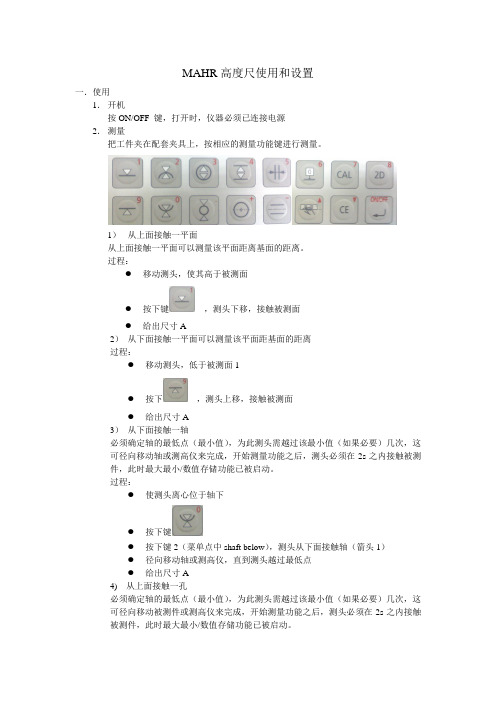
MAHR高度仪使用和设置
操作者自己决定何时按下键接收测量值,为此,可以一个较长的作用时间(100~
200秒间的任意值)。
2)分辨率(Resolution)
结果显示的分辨率是可调的
分辨率有五种选择:
1.0002um或0.00001inch.
2.0005um或0.00005inch
0.001um或0.0001inch
0.005um或0.0005inch
径向移动轴或测高仪,直到测头越过最高点
给出尺寸A
6)从下面接触一孔
必须确定轴的最高点,为此测头需越过该最大值(如果必要)几次,这可径向移动被测件或测高仪来完成,开始测量功能之后,测头必须在2s之内接触被测件,此时最大/最小数值存储功能已被启动。
过程:
使测头离心位于孔下
按下键
按下键2(菜单点中“Bore above max”),测头从下面接触孔
0.1um或0.001inch
3)日期和时间(Date and Time)
显示当前的日期和时间
借助光标键可以容易地将光标置于第一行,输入当前时间小时,分秒,而后按下回车键
现在用光标键选择本日所对应的星期几,而后按下回车键,确认输入日期(日,月年),而后按下回车键,当第3次按下回车键后,当前日期和时间就调整完了,若用ESC键离开上述菜单,所作的修改无效
DX1能自动校正高度测量仪或其它接入仪器的引入测量误差,欲了解详细信息,参考13节“测量仪器的校正因子”。
8)接触速度(Contacting speed)
DX1提供6种接触速度,对软材料和易损测头,应选择较低的接触速度,当用标准测头零件测量钢制被测件时,推荐使用速度2
9)Mm/inch
测量系统可在公制mm和英制inch间切换。标记该区,并按下回车键,会闪出可选单位制的窗口,按回车确认。
CR20机器人说明书

E
B
F
F
C D
F
图 2 搬运姿态
2-1
2.2 搬运固定夹具
2.1.2 使用叉车
使用叉车搬运时,请按照 " 图 3 使用叉车进行搬运的方法 ",将机器人安装在具有足够负载 能力的底板上,用螺栓固定,叉车叉子插入底板,连同机器人一起搬运。 搬运过程中注意不要发生倾倒或歪斜,缓速运送。
㶎ᷧ M16 (4 ໘) ᑩᵓ
• 搬运时避免过度的振动和冲撞。 否则对精密机器的性能会有影响
2.1 搬运方法
2.1.1 使用天车
机器人的开箱和移动、搬运,原则上请使用天车。 使用两根钢丝绳,利用环形吊装螺栓起吊搬运,请务必按 " 图 2 搬运姿态 " (出厂姿态), 用搬运夹具固定好之后再进行起吊搬运。
A
E
㺙㶎ᷧM10 (2 ໘) (㺙ᴀԧϞ)
MOTOMAN-CR20
机器人使用说明书
YR-CR20-A00 ( 标准型 )
请确保本使用说明书到达本产品的最终使用者手中。
MOTOMAN 使用说明书一览 MOTOMAN 安装手册 MOTOMAN-CR20 机器人使用说明书 YASNAC XRC 使用说明书 YASNAC XRC 操作要领书 入门篇 YASNAC XRC 操作要领书 应用篇
3.2 本体的安装方法
本体安装的好坏与否,对其功能的维持和确保起着非常重要的作用。尤其是,本体基座的固定 以及基础,必须要充分承受本体加减速时的反力和本体、夹具的静态重量。请提前进行确认, 并按照表一所示本体最大反力设计和施工能充分承受此最大反力的基础。此外,本体安装面的 的平面度差时,机器人会发生变形损坏设备。 请确保本体安装面的平面度在 0.5mm 以下。 基座的固定,请按照 " 3.2.1 在共用基座上安装本体和夹具时 " 或 " 3.2.2 本体单独直接 固定在地面上时 " 方法执行。
德国Mahr薄膜测厚仪C1208M和C1216M中文说明书(完整版)
8.1 怎样选择标准尺寸测量的类型……………………16 14.7 使用一条 0-模式线连接至 PC(配线图)……………35
8.2 输入一点标准尺寸测量的名义标准尺寸值………16 15 使用并行(I/0)接口……………………………………35
8.3 输入两点标准尺寸测量的名义标准尺寸值………16 15.1 数字式输出控制端………………………………………………11 14.6.1 数据传输至计算机时的接口配置…………………31
6 设置特性 1 的计算及显示……………………………12 14.6.2 数据传输至计算机时的接口配置…………………31
6.1 设置某一特性的准确显示值的因子………………12
M1240 接口协议……………………………………31
5 校正测头灵敏度………………………………………10 14.4 选择传输速度………………………………………30
5.1 校准通道 C1 的测头灵敏度…………………………11 14.5 选择传输频率………………………………………30
5.2 根据通道 C1 的测头灵敏度校正通道 C2 的测头 (只用 14.6 接口配置实例………………………………………31
在某个时间段(测量周期)内由测量数据统计出的最大值, 最小值及平均值都可以存贮在设备内. 测量周期 末期, 这些数据将用于特征计算, 并显示在屏幕上. 测量周期可通过 Millimar 键盘设置一个外接控制信号 或一个内置定时器.
根据接口协议设置, 测量结果可以通过 RS232 接口传输至外接计算机或由外接计算机发出询问信号, 也可 通过计算机进行设备参数询问或设置. 其它设备, 例如打印机, 程序控制器等 Millimar 延伸设备都可以连 接至接口, 用于某些辅助应用功能(I/O).
MEZRC-20A直流电阻测试仪

目录一、概述 (1)二、安全措施 (2)三、功能特点 (2)四、技术指标 (3)五、系统介绍 (4)六、测试与操作方法 (5)七、注意事项 (8)八、仪器成套性 (9)一、概述直流电阻测试仪是变压器制造中半成品、成品出厂试验、安装、大修、改变分接开关后、交接试验及电力部门预防性试验的必测项目。
可以检查绕组接头的焊接质量和绕组有无匝间短路,可以检测电压分接开关的各个位置接触是否良好以及分接开关实际位置与指示位置是否相符,引出线是否有断裂,多股导线并绕是否有断股等情况。
为了满足变压器直流电阻快速测量的需要,我公司研制的MEZRC-20A型直流电阻测试仪。
该仪器采用全新电源技术,具有体积小、重量轻、输出电流大、重复性好、抗干扰能力强、保护功能完善等特点。
整机由高速单片机控制,自动化程度高,具有自动放电和放电报警功能。
仪器测试精度高,操作简便,可实现变压器直阻的快速测量。
二、安全措施1、使用本仪器前一定要认真阅读本手册。
2、仪器的操作者应具备一般电气设备或仪器的使用常识。
3、本仪器户内外均可使用,但应避开雨淋、腐蚀气体等场所使用。
4、仪表应避免剧烈振动。
5、对仪器的维修、护理和调整应由专业人员进行。
6、测试完毕后一定要等放电报警声停止后再关闭电源,拆除测试线。
7、测量无载调压变压器,一定要等放电指示报警音停止后,切换档位。
8、测试过程中,禁止移动测试夹和供电线路三、功能特点1、整机由高速单片机控制,自动化程度高,操作简便。
2、仪器采用全新电源技术,电流档位多,测量范围宽,适合大中型变压器的直流电阻测量。
3、保护功能完善,能可靠保护反电势对仪器的冲击,性能更可靠。
4、具有声响放电报警,放电指示清晰,减少误操作。
5、响应速度快,可在测量状态直接转换有载分接开关,仪器自动刷新数据。
6、智能功率管理技术,仪器总工作在最小功率状态,有效节能,减少发热。
7、320X240点阵的超小像素点的65K真彩色液晶,8、仪器自带万年历时钟和掉电存储,可存储1000组测试数据,可随时查阅9、仪器配备RS232和USB接口,可和计算机通讯以及U盘存储四、技术指标1、输出电流:<5mA、1A、2.5A、5A、10A、20A2、最小分辨率:0.1μΩ1、量程: 100μΩ~1Ω(20A) 500μΩ~2Ω(10A)1mΩ~4Ω(5A) 2mΩ~8Ω (2.5A)5mΩ~20Ω (1A) 10Ω-20KΩ(<5mA档)3、准确度:±(0.2%+2字)4、工作温度:0~405、工作湿度:<90%RH,不结露6、外形尺寸:长325mmX宽240mmX高275mm7、重量:仪器13KG 线箱;5KG五、系统介绍仪器的面板见下图AC220 开关仪器工作电源,交流220V。
威德木尔 ACT20X 温度传感器数据表说明书

GermanyFon: +49 5231 14-0Fax: +49 5231 Product imageTypeACT20X-2HTI-2SAO-S Order No.8965480000Version EX signal isolating converter, Ex-input: I,ϑ, Safe-output: 4-20mA, 2-channel GTIN (EAN)4032248785094Qty.1 pc(s).The ACT20X-HTI-SAO / 2HTI-2SAO temperaturetransducers record temperatures from PT100 sensors and thermocouples from Ex zone 0. Current loops from 0(4) to 20 mA can also be connected on the input side.On the output side, there are active and passive current loops available for the safe zone.Integrated alarm contacts issue an alert in the event of a malfunction; this makes troubleshooting easier and increases system availability.The rail-mounted current output isolators are optionally available in one- or two-channel versions.With 11 mm width per channel, the devices need little space in the electrical cabinet.GermanyFon: +49 5231 14-0Fax: +49 5231 Width 22.5 mm Width (inches)0.886 inch Height 117.2 mm Height (inches) 4.614 inch Depth113.6 mm Depth (inches) 4.472 inchNet weight180 gHumidity0...95 % (no condensation)Operating temperature, max.60 °C Operating temperature, min.-20 °CStorage temperature, max.85 °CStorage temperature, min.-20 °COperating temperature -20 °C...60 °CStorage temperature-20 °C...85 °CMTBF111 YearsSIL in compliance with IEC 615082REACH SVHCLead 7439-92-1UL certificateE337701.pdfInput current0...20 mA, 4…20mAInput resistance, current 20 Ω + PTC 50 ΩLine resistance in measuring circuit≤ 50 ΩSensorRTD: PT10, PT20, PT50,PT100, PT250, PT300,PT400, PT500, PT1000,Ni50, Ni100, Ni120,Ni1000, Thermocouples:B, E, J, K, N, R, S, T ;in compliance with IEC 60584-1 and L,U in compliance with DIN43710Temperature input rangeConfigurableTypeintrinsically safe circuit,RTD, TC, DC (mA)or passive (as current sink)≤ 0.01% of span / 100 ΩOutput signal limit3.8…20.5 mA / 0…20.5mA (dependent on range)Output current0…23 mA, configurable:0…20 / 4…20 /20…0 / 20…4 mA,configurable downscale (3.5 mA) ⁄ upscale (23 mA)@ errorload impedance current≤ 600 ΩGermanyFon: +49 5231 14-0Fax: +49 5231 input, Short circuit at input,No supply voltage, Device errorRelay, 1 NC (voltage-free)Nominal switching voltage ≤ 125 V AC / 110 V DC (safe area)≤ 32 V AC / 32 V DC (zone 2)Continuous current≤ 0.5 A AC / 0.3 A DC (safe zone), ≤ 0,5 A AC / 1A DC (zone 2)Power rating≤ 62.5 VA / 32 W (safearea)≤ 16 VA / 32 W (Zone 2)ConfigurationWith FDT/DTM softwareVoltage supply19.2…31.2 V DC Type of connection Screw connectionPower consumption ≤ 1.4 W Step response time ≤ 400 ms (with current), ≤1 s (with temperature)Protection degree IP20Humidity0...95 % (no condensation)EMC standards DIN EN 61326, NE 21 Insulation voltage 2.6 kV (input / output)Rated voltage300 VVoltage U 08.7 V DC Current I 018.4 mAPower P 040 mWMarkingII (1) G [Ex ia Ga] IIC/IIB/IIA, II (1) D [Ex ia Da] IIIC, I (M1) [Ex ia Ma] IDemand modeHighDemand rate3,000 sDemand response timeSignal input: < 0.5 s (opto output), Temperatureinput: < 1.1 s (opto output)Description of the "safe state"analogue Output ≤ 3.6 mA or output ≥ 21 mA Device type BDiagnostic test interval30 s Hardware fault tolerance (HFT)0Mean Time To Repair (MTTR)24 h Safe Failure Fraction (SFF)90 %T proof3 Years Total failure rate for dangerous detectedfailures (λDD )367 FITTotal failure rate for dangerous undetected failures (λDU )61 FIT Total failure rate for safe detected failures(λSD )0 FITTotal failure rate for safe undetected failures (λSU )234 FIT Safety category SIL 2Probability of outage PFH6.1 x 10-8 h-1Demand (PFD avg )proof year), 6.5 x 10⁻⁴ (T proof = 2years), 1.41 x 10⁻⁴ (T proof =5 years)GermanyFon: +49 5231 14-0Fax: +49 5231 Type of connection Screw connection Tightening torque, min.0.4 Nm Tightening torque, max.0.6 Nm Clamping range, rated connection 2.5 mm²Clamping range, min.0.25 mm² Clamping range, max.2.5 mm²Wire connection cross section AWG,min.AWG 23Wire connection cross section AWG,max.AWG 14ATEX certificate10ATEX0020X.pdf IEC Ex certificateIECEx certification Certificate No. (ATEX)KEMA10ATEX0020XCertificate No. (IECEX)IECEXKEM09.0092XETIM 3.0EC002479 ETIM 4.0EC002479ETIM 5.0EC002479 ETIM 6.0EC002919UNSPSC 30-21-18-01 eClass 5.127-21-01-07eClass 6.227-21-01-07 eClass 7.127-21-01-07eClass 8.127-21-01-07 eClass 9.027-21-01-29eClass 9.127-21-01-29Product information Weidmüller provides an extended guarantee period of 36 months for this device.Approvals DNVGL;ROHSConformConformitySIL certificateCertification DNV GLDeclaration of Conformity Brochure/Catalogue CAT 4.1 ELECTR 16/17 EN Engineering Data EPLAN, WSCAD Engineering Data STEPSoftwareWI-Manager, DTM-Library for online installation V.1.2.0User DocumentationInstruction sheet ManualMAN SAFETY ACT20X-(2)HTI-(2)SAOGermanyFon: +49 5231 14-0Fax: +49 5231 application schematicDimensioned drawingscreenshot of temperature configurationwith FDT2 / DTM softwarescreenshot of current configurationwith FDT2 / DTM softwareGermanyFon: +49 5231 14-0Fax: +49 5231 14-292083screenshot of "observe" with FDT2 / DTM software screenshot of "diagnosis" with FDT2 / DTM software Connection diagram。
MG20可移动压力计器说明书

Specifications∙Portable Pressure-Calibrator∙Easy Operation∙Generating Over- and Under- Pressure ∙Measuring ranges from -1 up to 250 bar ∙Rugged, Compact, Light∙Integrated Datalogger∙Infrared Interface (IR)∙Average Value∙Battery operation∙Special Constructions available on request DescriptionThe mobile Pressure-Generator MG20 is equiped with our digital handheld pressure gauge HM35. It allows measurements of relative-, differential, or absolute-, pressure. The integrated pressure generator is capable of producing over-pressure up to 10 bar and under-pressure up to -800 mbar. Fine adjusting the pressure is done via integrated variable volume. Ex versions and media-compatible versions are also available. Functions such as pressure change rate, MIN/MAX and average value are available. At delivery, the MG20 comes including an SCS-certificate.MG20Technical DataPressure simulation is done via handpump and variable volumeOver-pressure range: 0…10 barUnder-pressure range: 0…-800 mbarAccuracyMeasuring range Resolution Max. Load capacity0... 200 mbar 0,01 1500 mbar 0,2% / 0,1%0... 300 mbar 0,01 1500 mbar 0,2% / 0,1% / 0,05% 0.1%0... 500 mbar 0,01 4000 mbar 0,2% / 0,1%0... 1000 mbar 0,01 4000 mbar 0,2% / 0,1% / 0,05% 0.1%0... 2000 mbar 0,1 7000 mbar 0,2% / 0,1% / 0,05% 0.1%0... 7500 mbar 0,1 17 bar 0,2% / 0,1% / 0,05% 0,1%0... 10 bar 0,0001 27 bar 0,2% / 0,1% / 0.05%0... 17 bar 0,0001 27 bar 0,2% / 0,1% / 0,05% 0.1%0... 35 bar 0,001 70 bar 0,2% / 0,1%0... 70 bar 0,001 140 bar 0,2% / 0,1% 0.1%0... 90 bar 0,001 140 bar 0,2% / 0,1% 0.1%0... 100 bar 0,001 140 bar 0,2% / 0,1% 0.1%0... 250 bar 0,001 500 bar 0,2% / 0,1% 0.1%0... 1100 mbar abs 0,01 4000 mbar 0,2% / 0,1%0... 2000 mbar abs 0,1 7000 mbar 0,2% / 0,1% / 0,05% 0.1%0... 7500 mbar abs 0,1 17 bar 0,2% / 0,1% 0.1%0... 10000 mbar abs 0,1 20 bar 0,2% / 0,1%0... 17000 mbar abs 0,1 30 bar 0,2% / 0,1%Measuring media: inert gases and instrument airMedia compatible rel./abs. all media which are compatible with stainless steel 18/8 (DIN 1.4305)Measurement units:mbar, bar, Pa, kPa, hPa, MPa,(depending on range) kg/cm2, kg/m2, mmHg, cmHg, mHg, inHg, mmH2O, cmH2O, mH2O,inH2O, ftH2O, psi, Ib/in2, lb/ft2, torr, atm∙Temperature calibration: 0 °C... 50 °C∙Operating temperature: 0 °C... 50 °C∙Humidity: max. 95 % rH∙Communication: serial Infrared (IR) Protocol and SCPI-commands∙Display rate: 2 M/s∙Power supply: 3 x 1.5 V battery IEC LR6∙Battery life time approx. 90 h or power supply unit 6 VDCapprox. 60 h EX-Version (no power supply connection available)∙Memory interval: manual, 10, 25 M/s, 1s... 24h selectable∙Pneumatic connection: hose Ø 4/6 mm NPT 1/8” (from 10 bar)∙Case, type of protection: IP 54∙Case dimensions: 158 x 108 x 259 mm ∙Weight without HM35: 2100 Gramm。
便携式气体检测仪使用说明书(测氧仪)
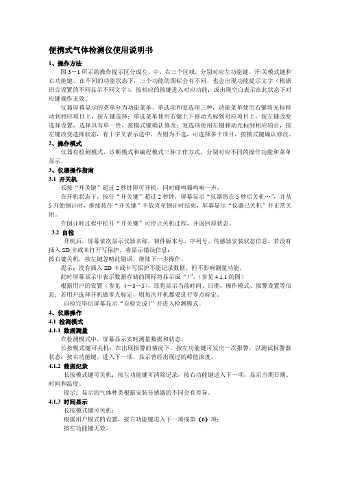
便携式气体检测仪使用说明书1、操作方法图3-1所示的操作提示区分成左、中、右三个区域,分别对应左功能键、开/关模式键和右功能键。
在不同的功能状态下,三个功能的图标会有不同,也会出现功能提示文字(根据语言设置的不同显示不同文字),按相应的按键进入对应功能;或出现空白表示在此状态下对应键操作无效。
仪器屏幕显示的菜单分为功能菜单、单选项和复选项三种,功能菜单使用右键将光标移动到相应项目上,按左键选择;单选菜单使用右键上下移动光标到对应项目上,按左键改变选择设置,选择具有单一性,按模式键确认修改;复选项使用左键移动光标到相应项目,按左键改变选择状态,有十字叉表示选中,否则为不选,可选择多个项目,按模式键确认修改。
2、操作模式仪器有检测模式、诊断模式和编程模式三种工作方式,分别对应不同的操作功能和菜单显示。
3、仪器操作指南3.1 开关机长按“开关键”超过2秒钟即可开机,同时蜂鸣器鸣响一声。
在开机状态下,按住“开关键”超过2秒钟,屏幕显示“仪器将在5秒后关机…”,并从5开始倒计时,继续按住“开关键”不放直至倒计时结束,屏幕显示“仪器已关机”并正常关闭。
在倒计时过程中松开“开关键”可停止关机过程,并返回原状态。
3.2 自检开机后,屏幕依次显示仪器名称、韧件版本号、序列号、传感器安装状态信息。
若没有插入SD卡或未打开写保护,将显示错误信息:按右键关机,按左键忽略此错误,继续下一步操作。
提示:没有插入SD卡或卡写保护不能记录数据,但不影响测量功能。
此时屏幕显示中表示数据存储的图标将显示成“!”。
(参见4.1.1的图)根据用户的设置(参见4-3-5),还将显示当前时间、日期、操作模式、报警设置等信息;若用户选择开机做零点标定,则每次开机都要进行零点标定。
自检完毕后屏幕显示“自检完成!”并进入检测模式。
4、仪器操作4.1 检测模式4.1.1 数据测量在检测模式中,屏幕显示实时测量数据和状态。
长按模式键可关机;在出现报警的情况下,按左功能键可发出一次报警,以测试报警器状态;按右功能键,进入下一项,显示曾经出现过的峰值浓度。
Mahr XC2仪器说明书
校正测针时,可根据平时主要测的参数选择依 照哪一参数进行校正,如Ra(或Rz)
日常使用注意事项二(轮廓度)
关于更换测针:
当进入软件界面后,在轮廓度的界面下,假如要进入粗糙度的操作,那么我们首先应该将轮廓仪的测 针卸载,然后再更换测针系统。否则,直接更换粗糙度的测针会造成软件无法响应。正常的操作为,先在 轮廓度下将轮廓度的测针卸载,然后更换为粗糙度仪的测针系统,也可在切换到粗糙度仪界面下,更换测 针系统。
当关闭软件后,从机器上将轮廓度仪的测针取下,重新进入软件后,提醒走参考点,由于此时没有轮 廓仪的测针,所以先取消,然后进入“Probe System”界面,而目前仍可看到是有测针的,假如此时点 “unload”卸载,然后再装载测针,同样会出现系统无法响应的问题。而正确的操作是,在关闭软件后,卸载 了测针,下次进入软件前,只需重新装上同样 的测针,然后就可走参考点。
粗糙度测量_参数选择
点此开 始测量
可在此设定是否 要在记录中显示 结果图形
粗糙度测量_正在执行测量
粗糙度测量_评定测量结果
粗糙度测量_结果报告设置
可在此输入公司名 等讯息
粗糙度测量_查看测量报告
日常使用注意事项一(粗糙度)
非特殊情况时,需要将粗糙度测针的保护套安 装上
在执行测量前,需要调整测头高度,调至测针与 被测面有1mm左右的高度,以免超出测针的可 活动范围
Mahr XCR20 软件操作说明书
马尔商贸(上海)有限公司 V1.0 制作: 田继军
操作说明书内容:
机器介绍 软件界面介绍 轮廓度部分说明 粗糙度测量 日常使用注意事项
机器介绍
Mahr CX1 DX1 操作手册

1. 简介 1.1 测高仪概述
Digimar CX1/DX1 精密高度测量仪(以下简称:测高仪)包括底座,测高仪 CX1,控制评估仪 DX1 及用 于测量工作面与基面两点间的距离的光栅测量系统。
测高仪类似于一个大型的垂直放置的卡尺,基座相当于卡尺的下量面,测头相当于卡尺的上量面。测 量空间由基座(2)及测头(1)界定。
2. 测高仪的控制及操作元件 2.1 测高仪 CX1
Digimar CX1
6
图 2 :测高仪 CX1(包括 DX1) 1. 控制评估仪 DX1 2. 显示屏 3. 图形键 4. 字母键 5. 气动开关 6. 搁手板 7. 运输手柄孔 8. 限位块 9. 测头(球形、柱形、盘形、锥形) 10. 测头夹头 11. 夹头紧固旋钮 12. 滑动手柄 13. 滑块 14. 上紧固头 15. 底座 16. 运输保护
生成一段测量程序最简单的方法是使用程序自学法。对于测量仅含几个被测件的较小程序,可以大大 的缩短测试时间。使用学习程序,无须手动编辑测量程序,只要按下一个键就能自动完成复杂的测量任务。 DX1 有一个可以存储诸如序列号,机器类型、产品批量、和检测仪名称等测量值及产品信息的数据库。数 据处理器能对这些数据进行统计,如直方图、控制图和排列图。
下都不能接通测高仪。 5. 本测高仪必须插在连有接地线的插座上。延伸电缆必须符合 VDE(德国工程师协会)或类似的标准。 6. 本测量仪的任何修改需要马尔公司的正式批准,并由具备相应资格的人员执行操控。未经许可拆开测
量仪或其他违反安全保证的行为,马尔公司对此不承担任何责任。拆开测量仪之前,必须关闭设备并 将主插头从插座上拔出。 7. 在清洁测高仪之前,须将插头从插座上拔出。不要将液体渗进测高仪!不要使用对塑料有害的清洁剂。 8. 如需更换保险丝,只能使用相同型号相同安培数的保险丝。在更换保险丝之前,要遵守操作手册中列 出的步骤。 9. 必须遵守所有的安全和事故预防条例。你的安全专家必须根据当地环境和室内方针提供更多的安全指 示。 10. 不要在充满爆炸性气体的室内操作测高仪,测高仪可能产生电火花,引发爆炸。 11. 不要将测量仪快速移向基座的边缘。承载测量的气垫不会立刻消失,在测量仪到达边缘之前使其减速, 否则可能导致测高仪摔下基座,伤到操作者。
智能型手持式便携式二合一气体检测仪说明书

三合一气体检测仪(手持式、便携式)操作手册2014年12月05日声明:本手册是多合一气体检测仪的通用操作手册,本手册中提到某些功能和界面,会因为检测仪实际配置的传感器不同而不同,在阅读时应注意区分。
软件升级后,界面和操作方法可能会有所变动。
纸质说明书通常都是批量印刷,所以如果有变动,不另行通知。
升级后我们仅提供最新版本的电子版本说明书,敬请谅解!本手册中所包含的所有数据和信息如有变更,恕不另行通知。
保留勘误权。
目录装箱单 (5)注意事项 (5)PID光离子传感器注意事项 (8)仪器参数 (10)校正采用的标准 (11)统计值的计算方法 (11)仪器报警的判断条件 (11)VOC气体规则 (12)仪器正面图解 (13)开机关机重启待机硬重启 (14)关于电池充电 (15)文字输入方法 (16)使用采样管和粉尘过滤器 (17)开始工作 (18)开始检测 (19)按钮示意 (20)菜单 (21)设置检测地点、检测时长、定时检测 (22)锁定与解锁 (23)查询数据 (24)使用电脑查询的操作方法 (26)打印检测结果 (27)启动打印 (27)设置打印机 (28)设置打印样式 (29)数据备份 (30)配置 (31)修改时间 (31)仪器工作方式 (32)传感器配置和标定 (33)配置模拟信号传感器 (34)模拟信号传感器的标定操作 (34)串口信号传感器 (36)PWM脉冲信号传感器 (37)气象环境传感器 (38)检测项目 (39)基本参数 (39)自定义公式 (40)【自定义公式应用案例】 (40)第2单位 (41)报警阀值 (42)文本表达 (43)密码设置 (44)屏幕亮度 (45)装箱单注意事项请仔细阅读本章节!1.收到货后,请确定仪器背部的标签型号是否是您订购的产品型号,如果有误,请及时与我们联系进行更换。
2.请仔细阅读产品说明书,熟悉操作方法。
3.本产品不能工作在要求有防爆的场所。
4.请注意防水、防摔、防震和防高压电,以免损坏仪器。
卡洛·加华齐控制系统 WM20 三相系统电能分析仪说明书

Compatible accessory modules
Type Digital outputs
Communication
Power supply (H or L) [kV]
-
4
4 4 4
Measurement inputs [kV]
4
-
4 4 4
Digital outputs [kV]
4
4 4 4
Serial port [kV]
4
4 4 NP
Ether-
Key • NP: combination not possible • 4: 4 kV rms insulation (EN 61010-1, IEC 60664-1, overvoltage category III, pollution degree 2, double insulation on
ules and manage up to two alarms.
Accessory module with two digital outputs. Expands main unit capacity, specifically allowing you to:
Transmit pulses proportional to energy consumption Control digital outputs (static or relay according to the module)
• Specific software. WM20 can be configured and measurements viewed from UCS configuration software (CARLO GAVAZZI). The software and subsequent updates are free.
Mahr测量仪器说明书

Chapter - page T est IndicatorsTesting of Test Indicators, Dial Indicators and Dial Comparators3-2 Test Indicators Puppitast3-3 Accessories for Test Indicators3-5Dial IndicatorsMechanical Dial Indicators3-7 Digital Dial Indicators Millitast3-12Dial ComparatorsMechanical Dial Comparator3-16 Mechanical Dial Comparators with Limit Contacts3-18 Mechanical Comparator with Limit Contacts3-20 Electrical Indicator 1141 SN3-20 Millimess, large type3-21 Inductive Dial Comparator Extramess3-22Accessories for Dial Indicators and Dial ComparatorsContact Points3-243-13-2+_+_T esting of T est Indicators, Dial Indicators and Dial ComparatorsAll test indicators, dial indicators and dial comparators are subject to a final inspection in production on Mahr measuring machines (865, 875 and Optimar 100).The following, in•DIN 2270 (test indicators)•DIN 878 (dial indicators)•DIN 879 (dial comparators)defined parameters, will be tested:D e v i a t i o n o f r e a d i n g f r o m s e t -p o i n t v a l u ePlunger being let outDiagram for the spans of error f e and f ges and hysteresis error of the measured value f u (example)Diagram of the span of error f t (example)D e v i a t i o n o f r e a d i n g f r o m s e t -p o i n t v a l u e• Span of error f eSpan of error f e is the distance between the ordinates of the highest and lowest points in the deviation diagram either when the plunger is being pressed in (dial indicators, dial comparators) or in the case of excursion of stylus against measuring force (test indicators).• T otal span of error f gesThe total span of error f ge s is the distance between the ordinates of the highest and lowest points in the deviation diagram when the plunger is being pressed in and let out (dial indicators, dial comparators) or in the case of excursion of stylus against and with the same direction of measuring force (test indicators). Thetotal span of error includes the hysteresis error of the measured value f u .• Local span of error f tSpan of error f t is the distance between the ordinates between the highest and lowest points in the deviation diagram,measured for a local measuring span of 10 scale divisions within 0,1 mm when the plunger is being pressed in (dial indicators, dial comparators) or in the case of excursion of stylus against measuring force (test indicators).• Repeatability f wRepeatability f w is a characteristic for measured value fluctuations in measurements of the same measurand within the measuring span and with the same direction of movement of the plunger (dial indicators, dial comparators) or of the stylus (test indicators).3-3Design features of Mahr Test Indicators Puppitast•Corrosion-proof due to satin-chrome finish on housing•Maximum sensitivity and accuracy provided by precision gears and pinions •Jewelled movement bearings•Overload protection provided by slip clutch •Low measuring force•Easy to read thanks to high-contrast, rotable dial face•Self-contained movement. This unit can be easily removed and quickly replaced for maintenance and repair purposes.•Insensitivity to magnetic fields•Box-type housing open on one side only•Bottom and side walls made of one piece. This shell totally encloses the movement and provides maximum protection against shock and damage•The front end of the housing is of fork-shaped design with the stem of the stylus mounted in the fork to provide highstability. The precision alignment of the two bearings ensures maximum accuracy•Automatic matching to sensing direction,i. e. pointer always moves in clockwise direction,thus ensuring error-free reading•Rigid mounting•Mounting shank can move on three dovetail guideways which are integral parts of the sturdy housing•They can be clamped at any desired point with a knurled nut. No tools are required.•No plastic parts except for transparent cover overdial face3-43-53-6Universal Holder 801 h•For mounting test indicators on machine tools•With swivel-type knuckle Order no.4309066AccessoriesCentering Support Rods 801 v•For aligning and centering workpieces on machine tools•Swivel mounting clamp and fine adjustment •Stainless steel rods Mounting bore dia.8 mm Swivel range of mounting clamp 180°Order no.4309070Stand 801 p•With swivel holder•Base with V-groove 140°Overall height 150 mm Mounting bore dia. 4 and 8 mm Column dia.8 mm Base surface 65 x 40 mm Order no.4309081801 p3-7Design features of Mahr dial indicators•Rising of measuring spindle by screw-in cable release•Protective housing only opens at the front. The housing is thus not simply a cylinder with a cap over it, but rather the back and side walls are machined from one piece. This shell totally encloses the movement and provides maximum protection against shocks and damage•Constant measuring force over entire range by virtue of compensation lever•Self-contained movement.Can be removed and replaced quickly and easily for repair or maintenance purposes•Maximum sensitivity and accuracy ensured by precision gears, pinion and rack as well as by precision guide for measuring spindle•T apered piece on mounting shank for easy insertion into mounting hole•Protective and lifter cap mounted on upper end of measuring spindle•Adjustable tolerance markers for setting tolerance limits•Corrosion-proof due to satin-chrome finish on housing and stainless, hardened steel for mounting shank and measuring spindle•Easy to read on account of high contrast dial •Simple fine adjustment with convenient knurled bezel•Shockproof movementOn all dial indicators with the exception of the long-range model 810 V the rack is not located directly on the measuring spindle, but rather on a sleeve which floats on the spindle. The shocks to which the spindle is subjected in everyday use are therefore not transmitted to the rack and mechanism. In the event of shocks, the sleeve lifts off and follows slowly due to spring force. The movement is thus reliably protected even against severe shocks.3-8803810/810 LDial Indicators shockproof version according to DIN 878803 W810 W3-9Dial Indicators shockproof version according to DIN 878810 B803 Z810 Z3-10Dial Indicators shockproof versionDial Indicators shockproof versionDial IndicatorsAccessoriesFeaturesDimensionsExtra-Large Dial Indicator 810 G with dial dia. 100 mm Design features identical to 810, but•Application for large reading distance and bad light conditions•Plastic outer ring•Delivered in folded box810 V 810 G810 U810 XDigital Dial Indicators 1083/1085 MillitastMillitast 1083•Functions:ON/OFFRESET (zero setting of display)PRESET (set buttons can be used to enter any numerical value)mm/inch-switchingDATA (data transmission in connection with data connection cable)Features•Data output:OPTO RS232C(Mahr Duplex)•Dial indicator can beoperated by remote controlvia interface•High-contrast 6,5 mm liquidcrystal display, analog displaywith 4 mm pointer lengthfor better visual perceptionwhen checking roundness Digital Dial Indicator1085Digital Dial Indicators 1083/1085 MillitastDigital Dial Indicator 1082Design features of Mahr dial comparators•Constant measuring force over entire range due to built-in compression spring •Shockproof movement.The precision ball of the first transmission lever rest on thelapped saphire plane surface of the upper end of themeasuring spindle. If the spindle is subject to severe impact,the plane surface is automatically raised, thus preventing transmission of the shock to the movement•Box-type housing only open at the front•Bottom and side walls made of one piece. This shell totallyencloses the movement and provides maximum protectionagainst shock and damage•Simple fine adjustment by way of lockable screw•Self-contained movement.This unit can be removed and replaced quickly andeasily for repair or maintenance purposes•Maximum sensitivity and accuracy are ensuredby jewelled bearings of movement inconjunction with precision gears and pinions•Corrosion-proof byvirtue of hardened,stainless steel mountingshank and measuringspindle•Protection of ball guide against contamination bymeans of a sleeve seal ring which is provided witha groove for mounting slip-on rubber bellows toprevent the ingress of splashwater•Drip-proof version available on request. Features rubber bellows at measuring spindle, sealed screws and splash guard cover•Measuring spindle mounted in high-precision ball guide prevents tilting andvirtually precludes friction and play. Theextremely low level of friction makes for high measurement accuracy and minimal hysteresis•Dial comparators with ball guide are particularly insensitive to lateral forces acting on the spindle (Dial Compa-rators 1010 and 1050 feature high-precision sleeve bearings for the spindle)•Easy to read due to clear-cut scale•Pointer moves over limited sector•Adjustable tolerancemarkers facilitate settingand observation oftolerance limits•Raising of measuring spindleeither by way of screw-incable or lifting knobMechanical Dial ComparatorsMechanical Dial Comparators10101050Mechanical Dial Comparators with limit contacts1103 N1110 N1150 N***Incl. plastic case, Setting Knob 953, cable (1,2m), Splash Guard Cover 958 and Rubber Bellow 970; Adapter 940 (for inch instruments only)Mechanical Dial Comparators with limit contacts Electrical specificationsMechanical Dial Comparator 1100 with limit contactsDial ComparatorsMechanical Dial Comparator Large Type MillimessInductive Dial Comparator 2000 ExtramessExtramess 2000•Functions:ON/OFFRESET (zero setting of digital and analog display) - 0 - (zero setting of analog display)PRESET (set buttons can be used to enter any numerical value)mm/inch switching Reversal of countingFeatures* including Adapter Bush 940** indicated value + display span of error (≤0,5 resolution)•Data output:alternatively OPTO RS232C or Digimatic•Dial Comparator can be operated by remote control via interface•High-contrast 6,5 mm liquid crystal display, analog display with 4 mm pointer length for better visual perception when checking roundnessInductive Dial Comparator 2000 ExtramessContact Points for dial indicators, dial comparators901Special Contact Points905904 H907 H908 H913906 H902903Contact Points for dial indicators, dial comparators910 H909 ASensor Lever 943Special Holders 941For all types of testing equipmentFor placing the dial indicator at a certain distance or angle Measuring spindle travel 3 mmContact Point 901 (interchangeable)941 G941 W912911 HPin Contact Point 911 HMeasuring Attachment 910 HContact Rollers 909Concentricity error 2 µmTransmission accuracy for 941 W max. 1%;for travel 3 mm = 0,03 mmMeasuring Spindle Extensions 912。
Comark KM20REF 温度计说明书

KM20REF REFERENCE THERMOMETERGENERAL INFORMATIONIt is recommended that you read the safety and operation instructionsbefore using this instrument.WARNINGTO AVOID DAMAGE OR BURNS, DO NOT MAKE TEMPERATURE MEASUREMENTS IN MICROWAVE OVENS.CAUTIONTemperature Measurement ProbesThis precision instrument has been designed for use with the extensive range of Comark temperature probes. The use of other probes may impair the performance and accuracy of the instrument. Full details of Comark probes and sensors can be obtained from Comark Customer Support department or your local distributor.Repeated sharp fl exing can break thermocouple probe leads. To prolong lead life, avoid sharp bends or kinks in the leads, especially near the connector.This instrument is manufactured in accordancewith the Company’s ISO 9001 Quality ApprovedSystem.This instrument complies with theElectromagnetic Compatibility DirectiveEN 61326-1.Declarations of Conformity available. ContactComark Customer Support or your localDistributor.In line with its policy of continuous development, Comark Instruments reserves the right to alter the instrument speci fi cation without prior notice. Further information is available from Comark Instruments or yourdistributor.ISO 9001FM 26700CALIBRATION, CERTIFICATION AND SERVICECerti fi cationComark can provide certi fi cates of calibration for its whole product range, to suit ISO 9000 and other quality assurance procedures, food hygiene regulations, HACCPs and environmental regulations. Comark certi fi cates are produced by independent quality controlled processes which compare product performance against agreed National Standards. For peace of mind and best practice Comark recommend annual certi fi cation/recalibration.Two levels of certi fi cation are available for infra-red temperature and nontemperature instruments, excluding humidity:- UKAS certi fi cates via an external accredited laboratory and NPL traceable certi fi cates from the Comark calibration laboratory.Three levels of certi fi cation are available for contact temperature and humidity products and these are detailed here:a) UKAS Temperature Certi fi cationThe Comark UKAS (United Kingdom Accreditation Service) accreditedtemperature calibration laboratory is one of the fi nest in the UK. Comark UKAS certi fi cates can offer the lowest uncertainty of 0.01°C andprovide independent proof of correct calibration using equipment andprocedures audited by UKAS inspectors. The equipment used is fullytraceable to the National Physical Laboratory.b) UKAS Humidity Certi fi cationIn addition to the Comark temperature laboratory, the humidity laboratory continues the tradition of high accuracy certi fi cation and a wide range(25% to 90%RH) with uncertainties of 2.8% of reading. This range also includes Dew point measurements.c) NPL Traceable Certi fi cationComark NPL certi fi cates are traceable to the National PhysicalLaboratory and can offer uncertainty as low as 0.3°C.ConformanceCerti fi cates of conformance can be supplied for new, serviced and recalibrated instruments. These con fi rm that instruments are within their original manufactured speci fi cation.Service/RepairsRegular servicing and any required repairs, under warranty or after, are available from the Comark Service Department.For more information on all Comark certi fi cation, calibration and service facilities please call Comark Customer Support or contact your local distributor.0451CHECKING THE ACCURACY OFFOOD TEMPERATURE MEASURING SYSTEMS US-ING THE KM20REF REFERENCE THERMOMETER The KM20REF thermometer has been specially confi gured and calibrated to provide an accurate and convenient method of checking the calibration of food temperature measuring systems. Each KM20REF is provided with a UKAS Certifi cate of Calibration from the Comark UKAS accredited calibration laboratory, which is traceable to NPL reference standards. This certifi cate defi nes the accuracy of theKM20REF at designated points.To maximise the stability of readings from the KM20REF or indeed any other reference thermometer it is recommended that:-a) i t is only used as a reference thermometerb) it is only used in ambient temperatures of +20°C ±5°Cc) it is protected from extreme temperature changes,shock and vibrationd) that only an alkaline battery is used and that this isreplaced after 25 hours of use.Food temperature measuring systems comprise two parts: the hand-held meter and the sensor (probe). It is important that the accuracy of the complete system (meter and probe) is regularly checked against the reading from a reference thermometer. To maintain traceable records both the meter and probe should be given unique serial numbers.To compare the reading from a food thermometer with the reference thermometer the following procedure may be applied:Note: A separate procedure has been devised for National Health Service catering operations, copies of which are available from Comark Ltd - Part Number 12442.Make sure that both the food thermometer and your KM20REF have both been at ambient temperature (between +15°C and +25°C) for at least one hour.Take a glass or plastic beaker that can safely hold at least 0.5 litres of fl uid.Mix cold water and if needed ice cubes made from tap water to achieve a mixture of water and/or ice (crushed ice is best) at a degree or sobelow your desired comparison temperature, say +4°C or +7°C as appropriate. You can use your reference thermometer for this.(0.5 litres of water in a plastic beaker at +7°C with an ambient temperature of 20°C exhibits a temperature rise of less than 0.1°C per minute.)Switch on both thermometers and insert both the probes into the water to a depth of at least 50mm (2 inches). Hold the probes so that their tips are very close together and use the probes to stir the water. The water should be stirred in the centre of the beaker away from the sides. The agitation rate should be approximately one rotation per second.Once the KM20REF is displaying the required temperature of comparison and this reading has been stable for 30 secs the reading of the food thermometer can be taken and recorded.If the reading from the food thermometer differs from the traceable reading of the KM20REF by ±0.5°C or more, the food thermometer and probe should be returned to the manufacturer for recalibration.Note: The traceable KM20REF reading is obtained by adding the appropriate adjustment. This adjustment is obtained by taking the applied temperature and subtracting the corresponding measured value. See the example below:Applied Temperature Measured Adjustment–18.0°C –18.2°C +0.20.0°C –0.1°C +0.1+5.0°C +5.1°C –0.1+8.0°C +8.1°C –0.1+20.0°C +20.2°C –0.2 Note: In an ideal world your tests should be conducted at exactlythe same points as those indicated in the “Measured” column of your KM20REF Certifi cate. For all practical purposes it is acceptable to apply the adjustment factor provided the readings are ±1.0°C of the “Measured” value.If then when conducting the test the following results were achieved KM20REF reading +8.1°CFood thermometer reading +8.5°Cyour results sheet would be fi lled in as follows:EXAMPLECALIBRATION CHECK RESULTS SHEETDATE: 2nd May 2001TIME: 0930AMBIENT TEMPERATURE: 21.3°CKM20REF SERIAL NUMBER: 1234FOOD THERMOMETER SERIAL NUMBERS:INSTRUMENT:06750231PROBE:KM20REF READING: +8.1°C–0.1°CADJUSTMENT TRACEABLE TEMPERATURE:+8.0°CFOOD THERMOMETER READING:+8.5°C+0.5°CDEVIATIONACCEPT/REJECTTESTED BY:CHECKED BY:CALIBRATION CHECK RESULTS SHEETDATE:TIME:AMBIENT TEMPERATURE:KM20REF SERIAL NUMBER:FOOD THERMOMETER SERIAL NUMBERS:INSTRUMENT:PROBE:KM20REF READING: °C°CADJUSTMENT TRACEABLE TEMPERATURE:°CFOOD THERMOMETER READING:°C°CDEVIATIONACCEPT/REJECTTESTED BY:CHECKED BY:Auto Switch OffThe KM20REF has an auto switch off function to conserve batterylife. The instrument will automatically switch off after approximately 3minutes use. Press the ON/OFF button again to continue using theinstrument.SPECIFICATIONSCALE °CMEASUREMENTRANGE Pt100–100°C to +199.9°C RESOLUTION 0.1°CACCURACY ±0.2°COPERATING RANGE0 to +40°CCERTIFICATE OFCALIBRATIONDESIGNATED POINTSFOR ACCURACY–18°C, 0°C, +5°C, +8°C, +20°C EMC Tested to EN 61326-1Criteria B performanceComark Instruments52 Hurricane Way,Norwich, Norfolk, NR6 6JB United Kingdom Tel: +44 844 815 6599Fax: +44 844 815 6598Email: s************************** Website: Comark InstrumentsPO Box 500, Beaverton,OR 97077 USATel: 503 643 5204Fax: 503 644 5859Email: s ales@comarkusacomWebsite: 。
LIFEPAK 20 20e 心电图监测器、外科救治器和同步心电图救治器的操作指南说明书

12.Prepares for additional countershocks if needed by repeating steps #6–12.
13.Presses CODE SUMMARY for documentation.
3. Prepares patient: • Bares patient’s chest. • Prepares electrode sites with brisk dry rub. • Describes additional preparation needed for patient with excessive hair, oily or damp skin.
4. Applies ECG electrodes: • Confirms package is sealed and use by date has not passed. • Attaches an electrode to each lead wire. • Inspects electrode gel for moisture content. • Identifies appropriate electrode sites for 3-wire cable in upper right, upper left, lower left torso areas; or 5-wire cable in upper right and left, lower right and left torso, and (c) in V4 location or as directed by local protocol. • Applies electrode flat to skin, smoothing tape outwardly and avoiding pressing on center of electrode. • Secures cable clasp to patient’s clothing (optional).
马尔XC20轮廓仪操作规程
马尔XC20轮廓仪操作规程马尔XC2&XC20 轮廓仪操作规程为安全高效的使用马尔轮廓仪,特制定如下操作规程:一.仪器的使用过程与步骤:1.检查仪器是否供电正常,需要220伏特+-10%供电电压。
2.打开PC主机电源。
3.进入WIN XP操作系统后,打开Midrange电源控制盒开关.4.鼠标左键双击桌面“MARSURF XC20&XC2”图标,开启软件。
5.进入软件,请登录用户ADMINISTRATOR,密码输入:marwin。
6.进入操作界面,请按下控制面板绿色按钮,给仪器加电。
7.执行参考点仪器复位。
注意:请检查驱动器是否加载对应的测针,如果测针卸载,请在“测量站”-“测针系统”-“加载测针:如:PCV350X33”,不加载测针无法执行仪器复位。
8.清洁工件待测位置,装夹工件,保持工件和测臂平行。
9.将仪器测头移动至工件待测位置,调节测量高度至合适部位。
10.在“测量助手”中根据需要及产品特征设置相应表头,零件测量长度,采样速度,滤波,抬高,回退,驱动(ON)等参数。
11.执行产品的测量。
12.测量结束后,在“评定”界面进行零件的尺寸参数评定,如X(水平距离),Z(垂直距离),R(轮廓半径),A(轮廓角度),直线度,轮廓度等。
13.保存评定结果。
14.打印报告,分析数据及轮廓特征。
15.仪器使用结束后,将立柱,测臂移动放置在安全位置,防止发生碰撞。
16.关闭测量软件。
17.关闭电源控制盒Midrange.18.关闭WINDOWS XP操作系统。
19.测量工件及夹具放置到合理位置。
20.清洁工作台。
二.安全事项:1.请注意供电的稳定,温湿度的控制(温度20+-2度,每日变化在1摄氏度以内,湿度控制在40%-60%。
),环境整洁,避免仪器直接太阳光照,减小震动对仪器的影响。
2.请注意清洁仪器时,不要用清洁剂和水去擦拭主机,CD120,PCV,等驱动器外壳,MIDRANGE控制盒,用干净的无尘纸和布清洁即可。
便携式互感器测试仪说明书

便携式互感器测试仪说明书由于输入输出端子、测试柱等均有可能带电压,在插拔测试线、电源插座时,会产生电火花,小心电击,避免触电危险,注意人身安全!安全要求请阅读下列安全注意事项,以免人身伤害,为了避免可能发生的危险,只可在规定的范围内使用。
只有合格的技术人员才可执行维修。
—防止火灾或人身伤害使用适当的电源线。
只可使用专用并且符合规格的电源线。
正确地连接和断开。
当测试导线与带电端子连接时,请勿随意连接或断开测试导线。
注意所有终端的额定值。
为了防止火灾或电击危险,请注意所有额定值和标记。
在进行连接之前,请阅读使用说明书,以便进一步了解有关额定值的信息。
使用适当的保险丝。
只可使用符合规定类型和额定值的保险丝。
避免接触裸露电路和带电金属。
有电时,请勿触摸裸露的接点和部位。
请勿在潮湿环境下操作。
请勿在易爆环境中操作。
-安全术语警告:警告字句指出可能造成人身伤亡的状况或做法。
目录一、概述 (5)二、主要技术指标 (5)三、使用环境条件 (6)四、测量原理 (6)五、使用方法1、面板配置 (7)2、操作键盘 (7)3、开机 (8)4、仪器复位 (8)5、误差测试 (8)6、电网频率测试 (14)一、概述HGQY-H便携式低校高式电压互感器测试仪是最适合于在现场对电压互感器进行误差测试的全自动智能仪器。
用户不再需要配置笨重的升压器,标准电压互感器,负载箱及调压器(或自动检测台),单台仪器就能对10kV、10kV/3、35kV、35kV/3、110kV/3、220kV/3的电压互感器进行快速测量。
全过程(包括额定、下限的所有测量点)的测试时间不超过1分钟(不含接线时间),其准确度达到0.05级。
本仪器采用320×240点阵的大屏幕液晶显示器,各点的误差可以在同一屏上显示,所有操作均可点击屏幕菜单轻松完成。
本仪器可以存贮200组数据,备有专用接口与PC机通讯。
本仪器约重15kg。
二、主要技术指标●测试范围:10kV、10kV/3、35kV、35kV/3、110kV/3、220kV/3●二次负荷:2.5VA~600VA cosФ=0.8●测量精度:0.05级●测频率:准确度为0.01Hz●仪器设有实时时钟,可实时记录测试时间。
- 1、下载文档前请自行甄别文档内容的完整性,平台不提供额外的编辑、内容补充、找答案等附加服务。
- 2、"仅部分预览"的文档,不可在线预览部分如存在完整性等问题,可反馈申请退款(可完整预览的文档不适用该条件!)。
- 3、如文档侵犯您的权益,请联系客服反馈,我们会尽快为您处理(人工客服工作时间:9:00-18:30)。
软件界面_测量工作站
上/下移动 测头
测针自动接触
左/右移动 测头(X方向)
手动移动速度控制
设定当前位 置为X零点
软件界面_测量工作站
更换测针 校正测针 新建测针 删除测针
轮廓度“meas. assistant”设置
点此进入 测量助手
测量长度 测量速度 测量力
接触方向 抬高距离 (测后)
返回起点
在测量完成后,请注意将测针移到一个安全高 度后,再将被测件取走,以免撞到测针
校正测针时,可根据平时主要测的参数选择依 照哪一参数进行校正,如Ra(或Rz)
日常使用注意事项二(轮廓度)
关于更换测针:
当进入软件界面后,在轮廓度的界面下,假如要进入粗糙度的操作,那么我们首先应该将轮廓仪的测 针卸载,然后再更换测针系统。否则,直接更换粗糙度的测针会造成软件无法响应。正常的操作为,先在 轮廓度下将轮廓度的测针卸载,然后更换为粗糙度仪的测针系统,也可在切换到粗糙度仪界面下,更换测 针系统。
启动电脑 开启MidRange 进入电脑的系统桌面后, 启动测量软件
Marsurf XCR20 选择相应的账户名称进入 在接下来出现的Reference对话框中, 点击OK
特别说明:
XCR20的回机器参考点动作,实际执行的是轮 廓仪驱动器.粗糙度的驱动器不需要做此动作. 因此在粗糙度界面要做归零时,需要先将轮廓 的测针装上,再执行.
Mahr XCR20 软件操作说明书
马尔商贸(上海)有限公司 V1.0 制作: 田继军
操作说明书内容:
机器介绍 软件界面介绍 轮廓度部分说明 粗糙度测量 日常使用注意事项
机器介绍
GD25 粗糙度驱动器
XY工作台 测量立柱
轮廓 度驱动器
机器介绍_粗糙度测头配置
测头 测针保护套
测针
如何启动机器?
关于测量注意事项:
在测量时,装夹完工件后,调整测针的位置,使其慢慢接触到所需测量部位的工件表面,此时你需要 观察 Z的示值以及工件表面的情况,保证在整段的测量过程中,Z不会超出其量程(长针±26,短针±13).如果 可能超过, 就需要调整立柱上测针的位置, 保证测量顺利完成.
轮廓度测量时各个选项
点此进入 (此键切换)
对所测轮 廓评价
所建立 的元素
评价过程
报告预览
所有评 价结果
测量报告
粗糙度测量_1
点此进入测量 参数设定界面
点此完成测 量参数设定
选择测量工件的数 目,在Off时默认为 1
选择粗糙度的扫描 长度
测量完成后,粗糙度测量_参数选择
点此开 始测量
可在此设定是否 要在记录中显示 结果图形
粗糙度测量_正在执行测量
粗糙度测量_评定测量结果
粗糙度测量_结果报告设置
可在此输入公司名 等讯息
粗糙度测量_查看测量报告
日常使用注意事项一(粗糙度)
非特殊情况时,需要将粗糙度测针的保护套安 装上
在执行测量前,需要调整测头高度,调至测针与 被测面有1mm左右的高度,以免超出测针的可 活动范围
