Fluke 718Ex_用户手册中文版(校准器)
福禄克FLUKE过程校准仪使用使用说明
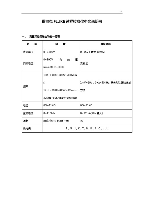
福禄克FLUKE过程校准仪中文说明书一,测量和信号输出功能一览表热电阻2,3,4线测量2线输出100ΩPlatinum(3926)100ΩPlatinum(385)120ΩNickel(672)200ΩPlatinum(385)500ΩPlatinum(385)1000ΩPlatinum(385)10ΩCopper(427)100ΩPlatinum(3916)压力27种压力模块从2.5kPa至69,000kPa *回路电压24或28V(22mA最大)*对于压力输出功能,是指由外部手动压力泵或其它压力源作为压力信号二、初识校准仪1.当你第一次取出校准仪,你需要将电池充电见图9,给电池充电2小时。
2.将电池放入校准仪中。
3.连接校准仪的电压输出端和输入端如下:连接最左端的一对插孔(V、Ω、RTD输出)和最右端的一对插孔(VMEAS)(见图3)。
图3 跨接线连接图4 输入输出的例子4.开机按⊙,按▲,▼以调整对比度。
以达到最好的显示效果。
校准仪在接通电源时是直流电压的测量功能,可以在一对VMEAS输入插孔中得到读数。
5.按看到其测量情况。
6.按V—…键,选择直流电压输出。
按数字键5和ENTER=开始输出5.0000V直流电压。
7.量直流电压。
你将在上半部屏幕看到测量读数,在下半部屏幕看到输出值,如图4所示。
三、操作功能1.输入和输出插孔图5所示,校准器输入和输出插孔,表2解释它的用途。
表2 输入/输出插孔和连接器7,8!SOURCE(输出)mA测量mAΩRTD插孔输出或测量电流、电阻和RTDS插孔,并提供回路电源9,10!SOURE(输出)V ΩRTD插孔输出电压、电阻、频率、和模拟RTDS输出插孔图5 输入/输出插孔和连接2.按键校准仪按键如图6所示,表3解释它们的功能,有4个未带标记的兰色按键,在显示屏幕下面称之为功能键。
其功能在操作过程中屏幕出现的定义所确定。
功能键和其显示内部在本手册中用黑体字标明,例如:Choices图6 按键表3 键的功能序号性能说明15 V-键测量方式中选择直流电压,输出方式中选择直流电压16 开关键电源开关3.显示屏幕图7为典型的显示屏幕。
Fluke Tis 中文说明书(使用手册)
Thermal Imaging Scanner
用户手册
June 2010 (Simplified Chinese) © 2010 Fluke Corporation. All rights reserved. Specifications are subject to change without notice. All product names are trademarks of their respective companies.
有限保证和责任限制
在正常使用和维护条件下,Fluke 公司保证每一个产品都没有材料缺陷和制造工艺问题。保证期为从产 品发货之日起二(2)年。部件、产品修理和服务的保证期限为 90 天。本项保证仅向授权零售商的原始 买方或最终用户提供,并且不适用于保险丝和一次性电池或者任何被 Fluke 公司认定由于误用、改变、 疏忽、意外非正常操作和使用所造成的产品损坏。Fluke 公司保证软件能够在完全符合性能指标的条件 下至少操作 90 天,而且软件是正确地记录在无缺陷的媒体上。Fluke 公司并不保证软件没有错误或无 操作中断。 Fluke 公司仅授权零售商为最终客户提供新产品或未使用过产品的保证。但并未授权他们代表 Fluke 公 司提供范围更广或内容不同的保证。只有通过 Fluke 授权 的销售商购买的产品,或者买方已经按适当的 国际价格付款的产品,才能享受 Fluke 的保证支持。在一个国家购买的产品被送往另一个国家维修时, Fluke 公 司保留向买方收取修理/更换零部件的进口费用的权利。 Fluke 公司的保证责任是有限的,Fluke 公司可以选择是否将依购买价退款、免费维修或更换在保证期 内退回到 Fluke 公司委托服务中心的有缺陷产品。 要求保修服务时,请与就近的 Fluke 授权服务中心联系,获得退还授权信息;然后将产品连同问题描述 寄至该服务中心,并预付邮资和保险费用(目的地离岸价格)。Fluke 对运送途中发生的损坏不承担责 任。在保修之后,产品将被寄回给买方并提前支付运输费(目的地交货)。如果 Fluke 认定产品故障是 由于疏忽、误用、污染、修改、意外或不当操作或处理状况而产生,包括未在产品规定的额定值下使用 引起的过压故障;或是由于机件日常使用损耗,则 Fluke 会估算修理费用,在获得买方同意后再进行修 理。在修理之后,产品将被寄回给买方并预付运输费;买方将收到修理和返程运输费用(寄发地交货) 的帐单。 本保证为买方唯一能获得的全部赔偿内容,并且取代所有其它明示或隐含的保证,包括但不限于适销性 或适用于特殊目的的任何隐含保证。FLUKE 对任何特殊、间接、偶发或后续的损坏或损失概不负责, 包括由于任何原因或推理引起的数据丢失。 由于某些国家或州不允许对隐含保证的期限加以限制、或者排除和限制意外或后续损坏本保证的限制和 排除责任条款可能并不对每一个买方都适用。如果本保证的某些条款被法院或其它具有适当管辖权的裁 决机构判定为无效或不可执行,则此类判决将不影响任何其它条款的有效性或可执行性。 Fluke Corporation P.O. Box 9090 Everett, WA 98206-9090 U.S.A. 11/99 Fluke Europe B.V. P.O. Box 1186 5602 BD Eindhoven The Netherlands
福禄克用户手册

®
Fluke 123/124 Industrial ScopeMeter
CH 2002 年 9 月 Rev. 4, 09/2009Байду номын сангаас
© 2002, 2005, 2007, 2008, 2009 Fluke Corporation. 版权所有。 所有产品名称均为其所属公司的商标。
用户手册
有限保修及义务范围
在正常使用与维修情况下,Fluke 保证每一个产品无质地及工艺问题。自发货之日算起,测试工具保修期为三年,附件保修期为一年。零配件及产品修理与维护的 保修期为 90 天。此保修只限于原始购买者和 Fluke 指定经销商的产品使用客户保修不适用于保险丝和普通电池,亦不适用于任何 Fluke 认为因错误使用、改装、 疏忽或因事故或非正常条件下操作或处置而导致损坏之产品。在 90 天内,Fluke 保证软件运转符合功能规范,且保证软件正确录制于完好无损的介质上。Fluke 不保证软件毫无差错或无操作中断情况。
或者与下列任何电话联系: 在美国与加拿大:+1-888-993-5853
在欧洲:+31-402-675-200 从其它国家:+1-425-446-5500
Fluke 714 热电偶校准器说明书

®714Thermocouple CalibratorInstruction SheetIntroductionThe Fluke 714 Thermocouple Calibrator is a precise source and measurement tool for calibrating thermocouple instruments. The calibrator sources or measures in units of °C, °F, or mV, through a thermocouple minijack.Your calibrator is supplied with a Flex-Stand ™ holster, aninstalled 9 V alkaline battery, and this instruction sheet. Sets of thermocouple miniplugs are available from Fluke. (Accessories Fluke-700TC1 and Fluke-700TC2 TC Miniplug Kits.)If the calibrator is damaged or something is missing, contact the place of purchase immediately. Contact your Fluke distributor for information about accessories. To order replacement parts or spares, see “Replacement Parts.”The following tables list the thermocouple types supported by the calibrator, the standards and scales used for each type, thethermocouple properties, and calibrator resolution. Full calibrator specifications are listed at the end of this instruction sheet.NoteSince mV input and output units are available, you can use the calibrator for any thermocouple type by making manual calculations or referring to tables.PN 650306 July 1997 Rev. 1, 10/97©1997 Fluke Corporation. All rights reserved. Printed in U.S.A.All product names are trademarks of their respective companies.1.888.475.5235*********************Fluke -Direct.comThermocouple Standards and Scales Thermocouple Type Standard Scale J, K, T, E, R, S, B NIST 175ITS-90 L (J-DIN), U (T-DIN)DIN 43710IPTS-68Thermocouple PropertiesThermocoupleType TemperatureRangesDisplay ResolutionJ-200 to 1200°C,-328 to 2192°F0.1°C or °FK-200 to 1370°C-328 to 2498°F0.1°C or °FT-200 to 400°C-328 to 752°F0.1°C or °FE-200 to 950°C-328 to 1742°F0.1°C or °FR-20 to 1750°C-4 to 3182°F1°C or °FS-20 to 1750°C-4 to 3182°F1°C or °FB600 to 1800°C1112 to 3272°F1°C or °FL-200 to 900°C-328 to 1652°F0.1°C or °FU-200 to 600°C-328 to 1112°F0.1°C or °F1.888.475.5235 *********************Millivolt Range and ResolutionMode Range Display ResolutionmV-10 to 75 mV0.01 mVExplanation of International SymbolsThe following symbols are used on the calibrator or in thisinstruction sheet. The table below explains their meaning.International SymbolsSymbol MeaningJ Earth groundI FuseM BatteryW Refer to this instruction sheet for information aboutthis feature.T Double insulatedConforms to relevant Canadian StandardsAssociation directives.P Conforms to European Union directives*********************1.888.475.5235Safety InformationW WarningTo avoid possible electric shock or personal injury:•Never apply more than 30 V between the TCterminals, or between either TC terminal andearth ground.•Make sure the battery door is closed andlatched before you operate the calibrator.•Remove an attached thermocouple miniplugfrom the calibrator before you open the batterydoor.•Do not operate the calibrator if it is damaged.•Do not operate the calibrator around explosivegas, vapor, or dust.When servicing the calibrator, use only specified replacementparts.Turning the Calibrator OnPress the green O pushbutton to turn the calibrator on and off.*********************1.888.475.5235Measuring a Thermocouple*********************1.888.475.5235Simulating a Thermocouple*********************1.888.475.5235MaintenanceFor maintenance procedures not described in this sheet, contacta Fluke Service Center.In Case of Difficulty•Check the battery and thermocouple test wiring. Replace as necessary.•Review this sheet to make sure you are using the calibrator correctly.If the calibrator needs repair, contact a Fluke Service Center. Ifthe calibrator is under warranty, see the warranty statement forterms. If the warranty has lapsed, the calibrator will be repairedand returned for a fixed fee. Contact a Fluke Service Center forinformation and price.CleaningPeriodically wipe the case with a damp cloth and detergent; donot use abrasives or solvents.CalibrationCalibrate your calibrator once a year to ensure that it performsaccording to its specifications. A calibration manual is available(PN 686540). Call 1-800-526-4731 from the USA and Canada. Inother countries, contact a Fluke Service Center.Replacing the BatteryWhen the M symbol appears on the display, replace thebattery with a 9 V alkaline battery.*********************1.888.475.5235it07f.eps Replacing the Fuse! WarningTo avoid personal injury or damage to thecalibrator, use only a 0.125A 250V fast fuse,Littelfuse® 2AG.Fuse F1 is probably blown if in the input mode, the calibratoralways reads OL, even with a thermocouple connected.*********************1.888.475.5235Replace the fuse as follows:1. Remove the test leads and turn the calibrator off.2. Remove the battery door.3. Remove the three Phillips-head screws from the casebottom and turn the case over.4. Gently lift the top cover from the end nearest the input/outputterminals until it unsnaps from the bottom cover.5. Replace the fuse with a 0.125 A 250 V fast fuse, Littelfuse®2AG.6. Fit the top and bottom covers together, engaging the twosnaps. Make sure that the gasket is properly seated.Reinstall the three screws.7. Replace the battery door.*********************1.888.475.5235ke03f.eps1.888.475.5235*********************Replacement Parts and AccessoriesReplacement PartsItem Description PN orQty.Modelno.BT19V battery, ANSI/NEDA 1604A or6144871IEC 6LR61CG81Y Holster, Yellow CG81Y1! F1Fuse, 125 mA, 250V fast6865271MP85Case top6202341MP86Case bottom6201681H2, 3, 4Case screw8322463MP89, 90Non-skid foot8244662MP92Battery door6199471H5, 6Battery door fasteners9486092S1Keypad6870761−714 Instruction Sheet5603061−71X Series Calibration Manual686540Option*********************1.888.475.5235H5, 6HolsterInstruction Sheetke04c.eps1.888.475.5235*********************Fluke -Direct .comSpecificationsSpecifications are based on a one year calibration cycle andapply for ambient temperature from +18°C to +28°C unlessstated otherwise. “Counts” means number of increments ordecrements of the least significant digit.Temperature Measure and Thermocouple SimulateTC Type Resolution Error ReferenceJunctionError J, K, T, E, L, U0.1°C or °F±(0.3°C + 10 µV)±0.2°CB, R, S1°C or °F±(0.3°C + 10 µV)±0.2°CMaximum input voltage: 30 VMillivolt Measure and SourceRange Resolution Accuracy-10 mV to 75 mV0.01 mV±(0.025% + 1 count)Maximum input voltage: 30 V*********************1.888.475.5235General SpecificationsMaximum voltage applied between any terminal and earthground or between any two terminals: 30 VStorage temperature: -40°C to 60°COperating temperature: -10°C to 55°COperating altitude: 3000 meters maximumTemperature coefficient: 0.05 x specified accuracy per °C fortemperature ranges -10°C to 18°C and 28°C to 55°CRelative humidity: 95% up to 30°C, 75% up to 40°C, 45% up to50°C, and 35% up to 55°CVibration: Random 2 g, 5 Hz to 500 HzShock: 1 meter drop testSafety: Certified as compliant to CAN/CSA C22.2 No.1010.1:1992. Complies with ANSI/ISA S82.01-1994.Power requirements: Single 9 V battery (ANSI/NEDA 1604A orIEC 6LR61)Size: 32 mm H x 87 mm W x 187 mm L (1.25 in H x 3.41 in W x7.35 in L);With holster and Flex-Stand: 52 mm H x 98 mm W x 201 mm L(2.06 in H x 3.86 in W x 7.93 in L)Weight: 332 g (11.7 oz);With holster and Flex-Stand: 584 g (20.6 oz)*********************1.888.475.5235How to Contact FlukeTo order accessories, receive operating assistance, or get thelocation of the nearest Fluke distributor or Service Center, call:1-800-44FLUKE (1-800-443-5853) in U.S.A. and Canada+31-402-678-200 in Europe+1-425-356-5500 from other countriesAddress correspondence to:Fluke Corporation Fluke Europe B.V.P.O. Box 9090,P.O. Box 1186,Everett, WA 98206-9090 5602 BD EindhovenU.S.A.The NetherlandsVisit us on the World Wide Web at: LIMITED WARRANTY & LIMITATION OF LIABILITYThis Fluke product will be free from defects in material and workmanshipfor three years from the date of purchase. This warranty does not coverfuses, disposable batteries or damage from accident, neglect, misuse orabnormal conditions of operation or handling. Resellers are notauthorized to extend any other warranty on Fluke’s behalf. To obtainservice during the warranty period, send your defective calibrator to thenearest Fluke Authorized Service Center with a description of theproblem.THIS WARRANTY IS YOUR ONLY REMEDY. NO OTHERWARRANTIES, SUCH AS FITNESS FOR A PARTICULAR PURPOSE,ARE EXPRESSED OR IMPLIED. FLUKE IS NOT LIABLE FOR ANYSPECIAL, INDIRECT, INCIDENTAL OR CONSEQUENTIAL DAMAGESOR LOSSES, ARISING FROM ANY CAUSE OR THEORY. Since somestates or countries do not allow the exclusion or limitation of an impliedwarranty or of incidental or consequential damages, this limitation ofliability may not apply to you.*********************1.888.475.5235。
福禄克仪表说明书

fluke设置说明
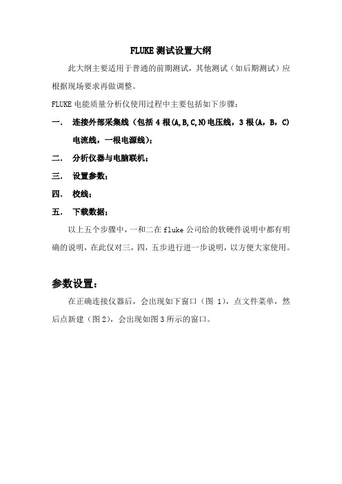
FLUKE测试设置大纲此大纲主要适用于普通的前期测试,其他测试(如后期测试)应根据现场要求再做调整。
FLUKE电能质量分析仪使用过程中主要包括如下步骤:一.连接外部采集线(包括4根(A,B,C,N)电压线,3根(A,B,C)电流线,一根电源线);二.分析仪器与电脑联机;三.设置参数;四.校线;五.下载数据;以上五个步骤中,一和二在fluke公司给的软硬件说明中都有明确的说明,在此仅对三,四,五步进行进一步说明,以方便大家使用。
参数设置:在正确连接仪器后,会出现如下窗口(图1),点文件菜单,然后点新建(图2),会出现如图3所示的窗口。
首先点硬件设置功能(图3所示),出现图4中的窗口。
在CH1,CH2,CH3三个通道(图中红圈处)输入PT变比,在CH5,CH6,CH7三个通道(图中绿圈处)输入CT变比。
其他不做改动。
例如,测量6kV母线,CT变比为1000A/5A,则设置为图5所示。
即电压变比应为实测电网电压除以100,电流变比应为用户提供的CT 变比的比值。
接下来,点击定值/极限菜单,如图6所示。
出现图7对话框,将额定电压(即红圈处)位置的数值改成所测母线的相电压值,即所测母线电压除以1.732(6kV为3464.20,10kV为5773.67,35kV为20207.85)。
注意,要在图中黄圈显示的菜单下才会出现额定电选项。
接下来,点击录模选项(图8所示),出现图9所示的菜单。
将连续记录中的RMS和谐波选项选中,然后将RMS和谐波的平均时间改成3000ms(这一项可根据测试要求不同做相应调整,主要是影响采样点的个数,因此将影响仪器记录数据时间的长短,一般前期测试用3000ms);把空闲间隔期的时间设置成10s(注意,测试时间如果超过8小时,该值设置成30秒)。
然后点击触发设置选项(图10所示),出现图11所示的窗口。
在弹出的窗口中,点击黄圈中所示的谐波选项,在该选项下,将红圈所示的电压总畸变处,将该数改成符合自己所测电网电压的数值。
Fluke 707Ex_用户手册中文版(毫安校准器)
FLUKE 多功能电气安全校准器 说明书
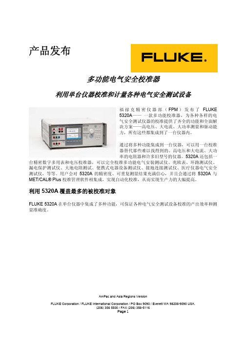
AmPac and Asia Regions VersionFLUKE Corporation / FLUKE International Corporation / PO Box 9090 / Everett WA 98206-9090 USA.(206) 356 5500 / FAX (206) 356-5116Page 1产品发布多功能电气安全校准器利用单台仪器校准和计量各种电气安全测试设备福禄克精密仪器部(FPM )发布了FLUKE5320A —— 一款多功能校准器,为各种各样的电气安全测试仪器的校准提供了齐全的功能和全面解决方案——高电压、大电流、大功率测量和驱动能力,所有这些都集成到了一台仪器内。
通过将多种功能集成到一台仪器,可以用一台校准器替代那些难以找得到的、高电压和大电流、大功率的电阻器和许多旧型号的仪器。
5320A 还包括一台精密数字多用表和电压校准器,可以完全校准多功能电气安装测试仪、兆欧表、环路测试仪、漏电保护测试仪、大地电阻测试、便携式电器设备测试仪、接地连接测试仪、医疗仪器电气安全测试仪,等等。
用户会对5320A 的精密度、可重复测量结果充满信心,并且会通过将5320A 与MET/CAL® Plus 校准管理软件相集成,实现自动化校准,从而实现生产力的大幅提高。
利用5320A 覆盖最多的被校准对象FLUKE 5320A 在单台仪器中集成了多种功能,可保证各种电气安全测试设备校准的产出效率和测量准确度。
谁是目标客户?主要的客户为直流/低频(DC/LF)校准实验室:第三方实验室内部校准实验室(公用事业部门、电信、电气制造厂商)部队/政府电气安全测试仪器制造商5320A的自动测试功能使其非常适合于生产测试和用于校准实验室。
被校准对象是什么?随着全球范围内电气安全标准的日益增多(包括英国的第16版测试标准和德国的VDE 0100及0700标准),电气安装和电器设备的测试成为电工和测试人员从事越来越多的常见任务。
FLUKE说明书
ENTER !"#$%& !"# !" 744
4
Auto Test ! !"#
!"#$%&#'()
!"#$%&' Send 4mA 20mA
!"#$%& Fetch
P !"# ì å á î É ê ë ~ ä Åçãã~åÇ e^oq
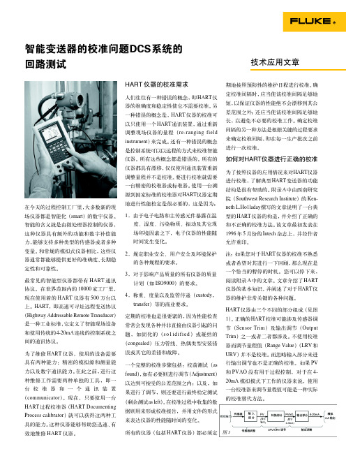
744 744 !"#$ sensor trim !"#$%&'() HART !"#$ 1 !"# !"#$%&'()*+',-. devide-specific command !"# 744 !"#$%&?
!"#$%&'$%( !"#$%#&'HART !"#$%&'() !"#$% smart !"# !"# 1 !"#$%&'()* !
Southwest Research Institute !"# Intech
!"#$%&'(
"#$%&'()*+, !" !"# !"#$%
!"#$%&'()*+ ,)!"#$%&'()*+,-( !"#$%&'()*+"# !"#$%&'() !"#$%&'()*+, !" # 2 !"#$% !"#$ !"#$ !" 3 !"
fluke718使用说明书

vi
更换电池.................................................................................................................... 21 零件和附件..................................................................................................................... 22
目录 技术指标 ........................................................................................................................ 25 压力传感器输入端 ..................................................................................................... 25 压力模块输入端 ......................................................................................................... 25 直流电(mA,毫安)输入......................................................................................... 25 回路供电.................................................................................................................... 25 一般指标.................................................................................................................... 26 如何和 Fluke 联系 .......................................................................................................... 27
Fluke 718系列压力校准器用户手册说明书

iii
718 Series 用户手册
iv
图目录
图
标题
页码
1. 连接方法 ................................................................................................................................ 5 2. 前面板特性 ............................................................................................................................ 6 3. 泵特性.................................................................................................................................... 9 4. 内部压力传感器带内部泵 ....................................................................................................... 12 5. 压力模块带内部泵.................................................................................................................. 13 6. 压力模块带外部泵.................................................................................................................. 17 7. 供应回路电压......................................................................................................................... 19 8. 更换电池 ................................................................................................................................ 21 9. 更换零件 ................................................................................................................................ 24
Fluke 网络自动测试器用户指南说明书

LinkRunner ®ATNetwork AutoTesterThe LinkRunner ® AT offers user-configured auto-tests for a wide range of important tasks. This network tester’s quick cable test and switch identification facilitates fast problem isolation. Test results can be automatically uploaded to the Link-Live results management cloud service to improve collaboration between network engineers and technicians, creating greater job visibility, project control, and fleet management.• Discover nearest switch name and port information via CDP/LLDP/EDP and verify link speed/duplex and connectivity to TCP/IP network with AutoTest • Validate up to 30W 802.3af/at PSE with TruePower™ loaded Power-over-Ethernet (PoE) test • Verify twisted-pair cable length and wire-map in a snap• AutoTest verifies and documents PoE, nearest switch, DHCP, DNS and Gateway service, and key devices connectivity in one go • Automate reporting and enable collaboration with result upload and management via Link-Live Cloud ServiceOverviewDATA SHEETLinkRunner AT is available in two models: LRAT-2000 and LRAT-1000. LinkRunner AT 2000 adds the following exclusive features:• Fiber support* • TruePower™ PoE Power Test up to 30W*• IPv6 support* • Reflector support* • More result storage: 50 instead of 10* • Uses Li-ION rechargeable battery instead of AA battery packKey FeaturesLeft: LRAT-2000 / Right: LRAT-1000*These exclusive features cannot be added to the LinkRunner AT 1000.Users can easily find opens, shorts, miswires, and split pairs in three different ways:• On non-terminated cable• With a WireView Cable Identifier• Check patch cord with the built-in wiremap port on the side of the LinkRunner ATCable LocationLocate cable runs with toning, switch port advertisement, switch port link light blinking, and remote cable identifiers. Toning supports both analog and digital IntelliTone modesThe LinkRunner AT uses the IEEE Link Layer Discovery Protocol (LLDP), along with the Ciscoand Extreme Discovery Protocols (CDP and EDP) to display the nearest switch model, slot, portand VLAN configured.The LinkRunner AT displays the following critical nearest switch information:• Switch name and model • Chassis, slot and port • Switch IP address•Voice and Data VLAN IDs• Duplex and speed (actual and advertised)• Signal Strength• Connection (MDI or MDI/X)• PoE voltage and power (actual and test limit)• Graphical representation of power on pairsThe LinkRunner AT features a packet reflector mode that allows the device to be used remotely during end-to-end network path performance tests to validate LAN and WAN throughput capabilities, up to 1Gbps. The reflector mode can be configured to swap MAC and/or IP addresses. LinkRunner AT 2000 supports packet reflection for:• EtherScope™ nXG Portable Network ExpertTruePower™ PoE Testing - Power Over Ethernet TestingLinkRunner AT features the ability to validate TruePower delivery before installing cameras, APs, and phones to ensure a smooth deployment. Quickly validate PoE performance by drawing actual power up to the 802.3at standard 25.5W. Load the circuit to stress switches, cabling and patch panels, all while measuring the voltage and pairs being used.IP V4/V6 AddressingValidate the IPv4 DHCP auto-negotiation process, subnet and DHCP server and verify IPv6 Link-Local and Global addressing.Switch informationCable wiring validationPacket Reflector ModePoE SetupAutoTest ResultsKey Service and Device ConnectivityLinkRunner AT can perform either a Ping or a TCP port open test to verify connectivity. The testconducted will reveal connection and response time to the default Gateway, preferred DNS server,and alternate DNS server. LinkRunner AT can connect to as many as 10 user-defined target devices,servers or services, testing using Ping, or a user-defined TCP port number. If a URL is used as thetarget, results will include response time and an IP address.802.1x AuthenticationVerify access to secure networks using 802.1x and MAC Access Control Lists (ACL). The includedLinkRunner AT Manager Software can be used to enable 802.1x and download certificates. AutoTest ResultsConfiguration SettingsAIRCHECK-G2-3YS 3 year AllyCare Support for AIRCHECK-G2, AIRCHECK-G2-KIT, AIRCHECKG2-TA-KT, ACKG2-LRAT2000 (covers ACKG2 only) and LR-G2-ACKG2-CBO (covers ACKG2 only)SpecificationsGeneralDimensions 3.5 in x 7.8 in x 1.9 in (8.9 cm x 19.8 cm x 4.8 cm)Weight18 oz (0.5 kg)Battery LRAT-1000 - 4 AA alkaline batteriesLRAT-2000 - Removable, rechargeable lithium-ion battery pack (18.5 Watt-hrs) Battery Life Typical operating life is 6 hours; Typical charge time is 3 hoursExternal AC Adapter/Charger AC input 90 to 264V AC 48 to 62 Hz input power DC output 15V DC at 1.2 Amps Display 2.8 in color LCD (320 x 240 pixels)Keypad12-key elastomericTone Generator IntelliTone™ digital tone: [500 KHz]; analog tones: [400 Hz, 1 KHz]Media Access; Copper RJ-45: 10BASE-T, 100BASE-TX, 1000BASE-T and PoE (IEEE 802.3af and 802.3at) Media Access; Fiber SFP Adapter Port supports 100BASE-FX and 1000BASE-LX/ SX/ZX (LRAT-2000 Only) Cable Tests Pair lengths, opens, shorts, splits, crossed, straight through, and cable IDPower over Ethernet (PoE)Single ended testing:- User-defined testing to IEEE 802.3at class 0, 1, 2, 3, 4 without LLDP negation, or 4 with LLDP negotiationThe following PSE PoE parameters are measured:- Pairs used- Received class- PSE type- Unloaded voltage(V)- Loaded voltage (V) (LRAT-2000 with TruePower™)- Unloaded power (W) (LRAT-1000)- Loaded power (W) (LRAT-2000 with TruePower™)EnvironmentalOperating Temperature 32°F to 113°F (0°C to +45°C)NOTE: The battery will not charge if the internal temperature of the tester is above 122°F (50°C).Operating relative humidity (% RH without condensation)90% (50°F to 95°F; 10°C to 35°C) 75% (95°F to 113°F; 35°C to 45°C)Storage temperature-4°F to 140°F (-20°C to +60°C)Shock and vibration Random, 2 g, 5 Hz-500 Hz (Class 2) 1 m dropSafety EN 61010-1 2nd editionSafety (LR-AT 2000 only)EN/IEC 60825-1:2007, EN/IEC 60825-2:2004+ A1:2007 (LRAT- 2000 only)Altitude4,000 m; Storage: 12,000 mEMC IEC 61326-1: Basic Electromagnetic Environment; CISPR 11: Group 1, Class A LinkRunner Manager SoftwareSupported OperatingSystems Windows® Vista, Windows® XP, Windows® 7, Windows® 8, Windows® 10Processor400 MHz Pentium processor or equivalent (minimum); 1 GHz Pentium processor or equivalent (recommended)RAM96 MB (minimum); 256 MB (recommended)Hard Disk Up to 500 MB of available space may be requiredDisplay1024 x 768 high color, 32-bit (recommended)Certifications and ComplianceSpecifications continued/products/linkrunner。
福禄克FLUKE过程校准仪使用说明书
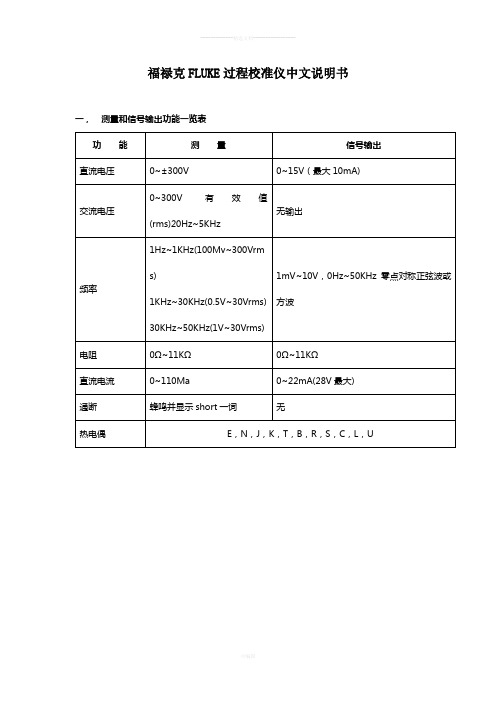
福禄克FLUKE过程校准仪中文说明书一,测量和信号输出功能一览表热电阻2,3,4线测量2线输出100ΩPlatinum(3926) 100ΩPlatinum(385) 120ΩNickel(672) 200ΩPlatinum(385) 500ΩPlatinum(385) 1000ΩPlatinum(385) 10ΩCopper(427) 100ΩPlatinum(3916)压力27种压力模块从2.5kPa至69,000kPa*回路电压24或28V(22mA最大)*对于压力输出功能,是指由外部手动压力泵或其它压力源作为压力信号二、初识校准仪1.当你第一次取出校准仪,你需要将电池充电见图9,给电池充电2小时。
2.将电池放入校准仪中。
3.连接校准仪的电压输出端和输入端如下:连接最左端的一对插孔(V、Ω、RTD输出)和最右端的一对插孔(VMEAS)(见图3)。
图3 跨接线连接图4 输入输出的例子4.开机按⊙,按▲,▼以调整对比度。
以达到最好的显示效果。
校准仪在接通电源时是直流电压的测量功能,可以在一对VMEAS输入插孔中得到读数。
5.按看到其测量情况。
6.按V—…键,选择直流电压输出。
按数字键5和ENTER=开始输出5.0000V直流电压。
7.量直流电压。
你将在上半部屏幕看到测量读数,在下半部屏幕看到输出值,如图4所示。
三、操作功能1.输入和输出插孔图5所示,校准器输入和输出插孔,表2解释它的用途。
表2 输入/输出插孔和连接器7,8!SOURCE(输出)mA测量mAΩRTD插孔输出或测量电流、电阻和RTDS插孔,并提供回路电源9,10!SOURE(输出)V ΩRTD插孔输出电压、电阻、频率、和模拟RTDS输出插孔图5 输入/输出插孔和连接2.按键校准仪按键如图6所示,表3解释它们的功能,有4个未带标记的兰色按键,在显示屏幕下面称之为功能键。
其功能在操作过程中屏幕出现的定义所确定。
功能键和其显示内部在本手册中用黑体字标明,例如:Choices图6 按键表3 键的功能序号性能说明15V-键测量方式中选择直流电压,输出方式中选择直流电压16开关键电源开关3.显示屏幕图7为典型的显示屏幕。
fluke说明书[1]
![fluke说明书[1]](https://img.taocdn.com/s3/m/7b07d69151e79b896802267c.png)
福禄克F430系列三相电能质量分析仪更快、更安全、更详细地定位和诊断的电能质量故障技术参数福禄克公司的F434 和F433三相电能质量分析仪可以帮助用户定位、预测、防止和诊断配电系统的故障。
对于那些维护或排障三相配电系统的工作人员来说,这些简便易用的手持工具是“必不可少”的。
新的IEC和GB国标关于闪变和电能质量方面的标准使得在对系统进行电能质量分析监测时有了判断的依据。
●记录三相系统中所有电能质量的参数。
●直观的菜单,最大程度上减少所需的设置。
●工业现场使用最高的安全等级。
●四个电压通道和四个电流通道。
●同时在所有相线上捕获波形数据。
●系统监测:在一个仪表板上现实全部电能质量参数。
●自动显示瞬态尖峰脉冲信号:不会漏掉任何一个事件。
●自动趋势绘图(AutoTrend)功能:无需对记录进行设置!●坚固的手持式设计。
●使用镍氢(NiMH)电池组时,一次充电可使用7个小时。
●将数据文件传输到PC,用于编写报告和利用FlukeView®软件进行分析。
CAT IV 600 V 和CAT III 1000 V的安全等级在设计时就考虑了保护用户和设备免受高压电击,福禄克F430系列电能质量分析仪、附件和充电器都经过验证,满足CAT IV 600 V和CAT III 1000 V环境下使用的严格的安全标准。
它们是同类别中第一款符合CAT IV安全等级的工具,所以可以被用于低压配电系统中所有的电气连接和插座。
快捷地观察趋势图利用AutoTrend(自动趋势绘图)功能,可以快速地深入浏览电能质量参数随时间的变化。
所显示的每一读数都被自动并且连续的进行记录,而不必设置触发限值或间隔时间,也无需手动启动记录过程。
可以快速地观察所有相线和零线上电压、电流、频率、功率、谐波或闪变的趋势图;还可以使用光标和缩放功能分析趋势-而不会中断记录。
AutoTrend功能在后台自动记录显示的所有参数。
在数据和趋势图之间切换,以及使用光标和缩放功能分析测量结果,都不会中断记录过程。
美国流克电子 Fluke 束距测试仪操作和保修说明书

LIMITED WARRANTY AND LIMITATION OF LIABILITY This Fluke product will be free from defects in material and workmanship for two years from the date of purchase. This warranty does not cover fuses, disposable batteries, or damage from accident, neglect, misuse, alteration, contam-ination, or abnormal conditions of operation or handling. Resellers are not authorized to extend any other warranty on Fluke’s behalf. To obtain service during the warranty period, contact your nearest Fluke authorized service cen-ter to obtain return authorization information, then send the product to that Service Center with a description of the problem.THIS WARRANTY IS YOUR ONLY REMEDY. NO OTHER WARRANTIES, SUCH AS FITNESS FOR A PARTICULAR PURPOSE, ARE EXPRESSED OR IMPLIED. FLUKE IS NOT LIABLE FOR ANY SPECIAL, INDIRECT, INCI-DENTAL OR CONSEQUENTIAL DAMAGES OR LOSSES, ARISING FROM ANY CAUSE OR THEORY. Since some states or countries do not allow the exclusion or limitation of an implied warranty or of incidental or consequential dam-ages, this limitation of liability may not apply to you.Fluke CorporationP.O. Box 9090 Everett, WA 98206-9090 U.S.A. Fluke Europe B.V. P.O. Box 1186 5602 BD Eindhoven The Netherlands11/99Table of ContentsTitle Page Product Statement (1)FoodPro Plus Specifications and Features (2)Proper Application and Operation (4)Before You Start (4)Noncontact (Infrared) Mode (4)Mode Selection (5)Probe Mode (5)Countdown (Timer) Mode (6)HACCP Check (7)Noncontact Temperature Measurement Applications (8)Measuring Liquid Temperatures (8)Measuring Packaged Products in ColdStorage Cases (9)Measuring Food at the Receiving Dock (10)Measuring Food in Holding and ServingAreas (10)Field Verification of Accuracy (10)Infrared (IRT) and Probe channels (RTD) (10)Cold Temperature Verification Check (10)Hot Temperature Verification Check (11)Field of View (12)Operating and Ambient Temperature Range . 13 Response Time (13)Humidity (14)Emissivity (14)Setting/Changing °C and °F TemperatureScales (14)Selecting the °C Scale: (14)Selecting the °F Scale: (15)Cleaning Instructions (15)Probe Replacement (16)Battery Insertion and Replacement (16)iFoodPro PlusUsers ManualTroubleshooting (17)Other Operational Considerations (17)Certifications (18)iiNoncontact Food SafetyThermometerProduct StatementThank you for purchasing this food safety thermometer. We are confident that you will be pleased with the quality and performance of this product. Please take a few moments to familiarize yourself with the operation, features, and benefits of this fine product. This food safety thermometer combines two precision thermometers in one unit: a specially calibrated noncontact infrared thermometer (IRT) and a calibrated resistance thermal device (RTD) penetration probe. The noncontact mode can be used for quick scans of a surface temperature, while the probe mode is used to accurately measure internal temperatures.1FoodPro Plus Users Manual2FoodPro Plus Specifications and FeaturesSee Table 1 for specifications and features. Specifications are subject to change without notice.Table 1. Specifications and FeaturesNoncontact Food Safety Thermometer FoodPro Plus Specifications and Features3Table 1. Specifications and Features (cont.)FoodPro Plus Users Manual4 Table 1. Specifications and Features (cont.)Proper Application and OperationBefore You StartFirst time users should reference “Battery Insertion Replacement” before using the unit.Noncontact (Infrared) ModePressing and holding the ON button starts the food safety thermometer in noncontact (infrared) measurement mode. The measurement will continue as long as the ON button is depressed, indicated by the blinking “SCAN”. When the button is released, “HOLD” appears on the display and the last measurement remains visible for 7 seconds before the display goes blank. The unit will display the temperature of an area highlighted by the target illuminator. The maximum reading is indicated in the lower portion of thedisplay (Figure 1).Figure 1. Noncontact (infrared) ModeNoncontact Food Safety Thermometer Proper Application and Operation5NoteThe infrared temperature measurements are used for screening and measuring surface temperatures only. Critical internal temperatures must be verified by using the probe. Mode SelectionThe SELECT button has two functions. Pressing the SELECT button after the display has gone blank will recall the last display. Pressing the SELECT button with an active display cycles through the three different operatingmodes: Noncontact, Probe, and Countdown Timer (Figure 2).Figure 2. IR Mode DisplayProbe ModeTo measure the internal temperature of an object, extend the probe (see Figure 3) and press the SELECT button until the Probe Icon is displayed (see Figure 4). Insert the probe at least 12 mm (1/2 ") into the target and press the ON button to measure the core temperature.The Probe Icon on the display will blink for approximately 15 seconds as the probe comes to equilibrium with the object being measured. Three short beeps will sound to indicate the reading is complete and the temperature will be shown on the display. When the highest accuracy is required, it is advisable to repeat the measurement cycle to insure the probe has fully stabilized and reached equilibrium with the object.FoodPro Plus Users Manual6Figure 3. Extended Contact ProbeFigure 4. Probe Mode DisplayNotesRemember if the display blanks the select button will recall the last measurement.The probe tip must be sterilized before and between measurements of food samples to avoid cross contamination. Countdown (Timer) ModeThe food safety thermometer has a built in countdown timer to conveniently monitor cooking, cooling, and critical exposure times, as well as Hazard Analysis Critical Control Points (HACCP) inspection intervals. HACCP principles and good food safety practices require monitoring the length of time perishable foods are exposed to temperatures that may support rapid bacterial growth.Noncontact Food Safety ThermometerProper Application and OperationTo set the countdown timer, press the SELECT button until the timer icon is displayed (Figure 5). Press the SET button once to enter the set mode (“SET” on display blinks). Press the SET button a second time to clear and increment the timer value. The timer value increases initially by 10 second intervals then by minutes and hours. The timer can be set for a maximum of 7 hours and 59 minutes.Once the desired timer value is set, pressing the ON button will start and stop the countdown. An alarm will sound for approximately 30 seconds when the timer reaches zero.NoteThe timer can be activated and running in the background(indicated by the flashing timer icon) during either IR or Probemeasurements or when the display is off. Pressing any buttonwill silence the sounding alarm.To clear the displayed timer value, press the SET button once to enter set mode and a second time to zero the timer value.HACCP CheckThis thermometer incorporates a “HACCP Check” feature to graphically display critical temperature zones. The icons and LED indicators located above the display indicate a food product is safely held at a sufficient holding temperature, or if it has fallen within the unsafe HACCP “Danger Zone” temperatures (Figure 5). The HACCP Check indicators operate in both the Noncontact and Contact modes. The indicator light will flash during an active measurement and will be lit steadily during display Hold or Recall (Figure 4).FoodPro PlusUsers Manual• A Green LED indicator shows a safe chilled or frozen condition below 5 °C (41 °F) or a safe holding temperature above 57 °C(135 °F).•The Red LED indicator light is displayed when temperatures are within the HACCP “Danger Zone” of 5 °C to 57 °C (41 °F to135 °F) where microbe growth occurs most rapidly (Figure 5).NotesWhen the temperatures within ±1 °C (±2 °F) of the HACCP“Danger Zone” boundary, both the relevant Green and Red LEDindicator lights will be triggered to alert the user of the bordertemperature.Whenever the Red LED indicator light is lit it is necessary toevaluate the safe storage and handling rules dictated by bothexposure time and temperature.Noncontact Temperature Measurement Applications Measuring Liquid TemperaturesTo accurately measure the temperature of liquids and semi-liquids, such as soup, chili, salad dressing, etc., stir the liquid to bring the internal temperature to the surface, while taking a measurement with the unit in noncontact mode. Steam, dust, smoke, etc., can prevent accurate measurement by interfering with the energy emitted from the target. To increase the reliability of the measurement, do not hold the unit directly over a steaming or smoking product. Instead, hold the unit back and at an angle to ensure the most accurate measurement (Figure 6).Figure 6. Measuring Liquid TemperaturesMeasuring Packaged Products in Cold Storage Cases Ideally, the temperature of a product should be measured outside of a refrigerated environment whenever possible. If it is necessary to measureNoncontact Food Safety ThermometerNoncontact Temperature Measurement Applicationsthe product in a refrigerated environment such as a walk-in cooler, either make rapid measurements (within 1 minute or less) or allow 30 minutes for the unit to stabilize in the refrigerated environment (above 0 °C / 32 °F) before measuring. To measure an item within a storage case, open the door or curtain, and directly scan the product for uniform temperatures. The presence of warmer areas may indicate improper stocking resulting in blocked airflow in the cabinet (Figure 7).Figure 7. Measuring Packaged ProductsNoteThe unit will not measure through glass or plastic doors. Measuring Food at the Receiving DockUse the food safety thermometer to accurately measure perishable products at the receiving dock. When a delivery of fresh or frozen food arrives, check that the products, shipping crates, and internal temperature of the delivery truck are all at the proper storage temperatures. Check for warm spots in products that can result from improper stacking and blocked airflow.Measuring Food in Holding and Serving AreasUse the noncontact thermometer to easily scan and accurately measure surface temperature of products held in hot or cold holding areas, such as open-top refrigeration units, steam tables, salad bars, fresh meat or fish displays and warming ovens.Use the HACCP Check feature to quickly identify unsafe temperatures within the HACCP “Danger Zone” of 4 °C to 60 °C (39 °F to 140 °F) by slowly scanning across the surface of food, storage containers, theFoodPro PlusUsers Manualcontents of delicases, chilled salads and desserts, holding ovens, rotisseries, etc.NoteIf any questionable temperatures are indicated or if temperaturereadings are within ±1 °C (±2 °F) of the HACCP “Danger Zone”boundary, use the probe to check internal temperatures.Field Verification of AccuracyInfrared (IRT) and Probe channels (RTD)Follow the steps below to verify the accuracy of your food safety thermometer. The 0 °C (32 °F) “stirred ice bath” is the recommended verification reference point. Since it is more difficult to measure the surface of hot water, the hot verification should be used only as a general accuracy check of the IRT channel.Cold Temperature Verification Check1.Fill a large styrofoam cup halfway to the surface with ice cubes.Add cold water to just below the rim of the cup.2.Immerse the tip of a known calibrated probe thermometer(reference probe) into the water and stir the mixture with theprobe for one minute, or until the probe temperature stabilizes.3.Continue stirring the water with a straw or swizzle stick whiletaking simultaneous temperature measurements with thereference probe and the IR thermometer. The unit should beheld within 3 inches of the surface of the water (Figure 8). Toinsure measurement accuracy the probe tip must be immersedto a minimum depth of 12 mm (1/2 ").Noncontact Food Safety ThermometerField Verification of AccuracyFigure 8. Cold Temperature Verification CheckThe noncontact (IRT) measurement should be within ±1 °C (±2 °F) of the reference probe reading (nominally 0 °C (32 °F)).The probe temperature reading should be within ±0.5 °C (±1 °F) of the reference probe reading.Hot Temperature Verification Check1.Follow the same procedure as above, substituting hot water(>140 °F/60 °C). Hot tap water is adequate for the procedure.2.Repeat steps two and three from above.NoteDue to evaporative cooling on the surface of the hot water, it isparticularly important that the surface of the water becontinually stirred while making the IR measurement (Figure 9).FoodPro PlusUsers ManualFigure 9. Hot Temperature Verification CheckUsing this method, the noncontact (IRT) channel should be considered accurately calibrated if the reading is within ±2 °C (±3.5 °F) of the reference probe’s reading; the unit’s probe reading should be within ±0.5 °C (±1 °F) of the reference probe reading.Cautions•Hold the noncontact thermometer outside the rimof the cup, approximately 3 inches from thesurface of the water.•Avoid steam condensation on the unit’s lens. Ifcondensation forms, carefully wipe the lens or letit dry at room temperature and resumemeasurement.Field of ViewThe ideal working range of the noncontact thermometer (IRT) is between 25 mm and 250 mm (1 and 10 inches) or the field of view from the target to the unit, divided by 2. The built in target illumination beam helps to indicate the measurement area. To ensure accurate measurements, the measurement target must fill or exceed the field of view. When conditions permit move in closer to the subject (Figure 10).Noncontact Food Safety ThermometerField Verification of AccuracyFigure 10. Noncontact Thermometer Working RangeOperating and Ambient Temperature RangeThe food safety thermometer is designed to operate in environments between 0 °C – 50 °C (32 °F – 122 °F). Avoid subjecting the unit to extreme or abrupt changes in ambient temperatures. Allow the unit to stabilize for a minimum of 30 minutes if exposed to rapid temperature changes. Failure to precondition the instrument to the ambient temperature may result in measurement errors (Figure 11).Figure 11. Ambient Temperature RangesResponse TimeThe response time of the instrument from initial start up is less than 1 second. The temperature display is updated at approximately 2 times per second during sustained operation.FoodPro PlusUsers ManualHumidityNoncontact thermometers (IRTs) are not intended for use in extremely humid or condensing environments. Condensation on the lens window will impede the optical performance and prevent accurate temperature measurements. If this occurs, allow the window to dry by evaporation or wipe with a soft cloth and resume measurements.EmissivityA noncontact thermometer (IRT) determines temperature by measuring the emitted energy of an object. Emissivity (E value) is the measure of an object’s ability to emit infrared energy.This noncontact thermometer is specially calibrated for high emissivity targets and is preset to an E value of ~0.97. This setting is the most advantageous for capturing the emitted energy from water, oils, shortening, fat, vegetables, as well as frozen, partially frozen and refrigerated products in boxes and plastic containers.NoteShiny metal surfaces (such as polished or stainless steel) havelow emissivities and reflect the energy of their surrounding,resulting in inaccurate temperature readings. The emissivity ofshiny metal surfaces can be enhanced to provide more accuratereadings by covering the measurement area with masking tape,flat black paint, or a coating of shorting or oil. Blackenedcooking surfaces such as griddles and cast iron pans makegood targets.Setting/Changing ºC and ºF Temperature ScalesThe food safety thermometer can display temperature in either the °C (Celsius) or °F (Fahrenheit) scales. The desired scale is selected at the time the battery is installed:Selecting the °C Scale:When the battery is connected to the battery leads the °C scale indicator shows on the display for approximately 15 seconds. If the SET button is not pressed the unit will time out and default to the °C or Celsius scale. Selecting the °F Scale:If the SET button is pressed within 15 seconds of connecting the battery to the battery leads, the temperature scale display will toggle to the °F scale indicator and the unit will now default to the °F or Fahrenheit scale (Figure 12).Noncontact Food Safety ThermometerSetting/Changing ºC and ºF Temperature ScalesFigure 12. Setting/Changing °C and °F Temperature ScalesNoteThe °C/°F temperature scale initialization process must beperformed whenever battery power is interrupted or the batteryis replaced.Cleaning InstructionsThis food safety thermometer is sealed to IP54 standards. The unit may be wiped down with a wet sponge or cloth using a mild water based detergent or anti-bacterial soap and rinsed under a gentle stream of cold water (Figure 13).Figure 13. Cleaning InstructionsNoteThis unit is not designed for complete submersion or washingin automated dishwashers.FoodPro PlusUsers ManualProbe ReplacementThe modular probe of the food safety thermometer is replaceable. To replace probe, extend the probe partially to access the rubber caps. Carefully pry up the rubber caps using a pin, and remove the screws using a #2 cross-tip screwdriver as shown. Grasp the probe and carefully separate the old probe from the probe base. Install the new probe in the reverse order, firmly tightening the screws and replacing the rubber plugs. The calibration accuracy of the unit is not affected by probe replacement (Figure 14).Figure 14. Probe ReplacementBattery Insertion and ReplacementTo install a new 9V battery, remove the rubberized battery compartment “plug” at the base of the unit by grasping the sides of the cover and pulling straight out, exposing the battery. Gently shake or tap the base of the unit on your palm to gain access to the battery. The 9V battery of the unit is connected to the polarized snap connector (Figure 15).Figure 15. Battery Insertion and ReplacementNoncontact Food Safety Thermometer Setting/Changing ºC and ºF Temperature Scales17NoteEach time the battery is installed or replaced, the temperature scale will default to the Celsius scale. To select the Fahrenheit scale see ‘Setting/Changing °C and °F Temperature Scales’. TroubleshootingCode:--- (on display) Problem:Target temperature is over or under range Action:Select target within range specifications Code:Battery Symbol Problem:Possible low battery Action:Check and/or replace battery Code:Blank display Problem:Dead battery or unit failure Action: Check and/or replace battery. If the battery is OK, then contact a Fluke service center for repair.Other Operational ConsiderationsAll models are protected from the following:• EMI (Electro Magnetic Interference) from induction heaters and microwave ovens• Electrostatic discharge• Should the unit become damaged, check the accuracy of the unit by performing the verification process recommended in this manual. If the unit is out of calibration, do not rely on it for critical temperature measurements. Contact a Fluke service center for repair,• Heat from stovetops, pans, or other hot surfaces (don’t set it on the stove)FoodPro Plus Users Manual18 CertificationsCE, NSF, CMCThis instrument conforms to the following standards:• EN 61326-1 Electromagnetic Emissions and Susceptibility • EN 61010-1 General Safety• IP54Pƒ。
Fluke 707_用户手册中文版(回路校准器)
出类型。 校准器在 0-20 毫安或 4-20 毫安量程间距内以三种斜波输出类型之一 施加或控制一个不断重复的毫安信号: 慢 (e) 40 秒内 0 % 到 100 % 到 0 % 平缓斜波输出。 快 (g) 15 秒内 0 % 到 100 %到 0 % 平缓斜波输出。 步进 (f) 以 25 % 为步长,从 0 % 到 100 % 再到 0 % 的阶梯斜波
清洁 定期用湿布和清洁剂清洁仪表外壳,切勿使用腐蚀剂或溶剂。
校准 每年校准一次校准器可确保它的性能符合指标要求。
更换电池
W 警告
为避免错误的读数而可能导致触电或人身伤害,显示屏上出现 M (电池电能过低) 符号时,应立即更换电池。
只用一节正确安装的 9 伏电池给校准器供电。
校准器使用一节 9 伏碱性电池(ANSI/NEDA 1604A 或 IEC 6LR61)。 若要更换电池:
1. 按 D 关闭 (OFF) 校准器。
2. 从端子断开测试线。
3. 取下皮套。
4. 如图所示打开校准器后部的电池盖。
5. 取出电池。
6. 放入更换的电池,关上电池盖。确保电池固定在位。
7. 把校准器放回皮套内。
ADA07F.EPS
HART 模式
要启用或禁用校准器的 HART 模式(HART,可寻址远程传感器数据 公路),请参见“按钮功能”部分的“开启选项”。缺省状态下, HART 电阻器关闭。
707 LOOP CALIBRATOR
CAT 30V
COM
+
AMP03F.EPS
用回路电源测量直流毫安
W小心 为避免测试时损坏被测装置,确保在连接测试线之前,先将校准 器置于正确的模式。 在回路电源档下,校准器能为变送器提供 +24 伏的回路电源,并同时 读出回路电流。 用回路电源测量直流毫安
FLUKE718压力校准仪说明书
页
1 2 6 8 9 9 14 16 17 17 18 18 18 19 20
i
718 30G/100G
用户手册 零件和附件 ............................................................................................................... 指标.......................................................................................................................... 压力感应器输入, 718 30G ..................................................................................... 压力感应器输入, 718 100G ................................................................................... 压力模块输入, 718 30G 和 718 100G .................................................................... 直流毫安输入, 718 30G 和 718 100G .................................................................... 回路电源 718 30G 及 718 100G ............................................................................ 综合指标 ............................................................................................................... 如何和 Fluke 联系 .....................................................................................................
Fluke应用软件中文说明
Fluke View和Fluke Power Log软件使用手册 1.软件的安装:Fluke view软件的安装:注:以下演示的安装过程以及以后的相关操作,均以 Power View(Version 3.31)软件的操作为实例,其它版本的相关操作也可以参考此版本。
a)将 Fluke view软件的安装光盘放入电脑的光盘驱动器中,光盘自动运行,则出现如图 1 所示的安装向导界面:b)点击第二项“Fluke View Power Quality Analyzer V3.31”,出现如下窗口:c)点击“Install FlukeView PQ Analyzer V3.31”,出现如下窗口:d)点击确定,此时软件被自动安装:e)此对话框提示您选择软件的安装路径,您可以对此路径进行修改,在此安装 向导的界面中点击 “Next >” 按钮f)安装向导将会转到下一步,如图所示,此对话框显示了该软件的版权许可,:g)对话框将显示 Fluke View软件的安装过程,该过程以一个进度条来显示如下所示:h)安装完成后,安装向导则会自动弹出一个询问对话框,询问您是否阅读文件信息或者直接进入运行程序。
Fluke Power Log 软件的安装:注:以下演示的安装过程以及以后的相关操作,均以 Power Log(Version 2.5)软件的操作为实例,其它版本的相关操作也可以参考此版本。
a)将 Fluke Power Log 软件的安装光盘放入电脑的光盘驱动器中,光盘自动运行,则出现如图 1 所示的安装向导界面:图 1. 软件的安装向导界面b) 点击“Install Power Log V2.5”,出现如下窗口:图 2. 软件的版权许可界面c)在版权许可界面中点击 “Next >” 按钮,安装向导将会转到下一步,如图 3 所示,此对话框提示您选择软件的安装路径,您可以对此路径进行修改:图 3. 软件的安装路径界面d) 对软件的安装路径进行选择后,如果点击 “Cancel” 按钮,则会结束此安装向导,退出安装。
- 1、下载文档前请自行甄别文档内容的完整性,平台不提供额外的编辑、内容补充、找答案等附加服务。
- 2、"仅部分预览"的文档,不可在线预览部分如存在完整性等问题,可反馈申请退款(可完整预览的文档不适用该条件!)。
- 3、如文档侵犯您的权益,请联系客服反馈,我们会尽快为您处理(人工客服工作时间:9:00-18:30)。
718Ex 30G/100G/300G Pressure Calibrator
May 2004 Rev. 2, 5/09 (Simplified Chinese)
© 2004-2009 Fluke Corporation. All rights reserved. Specifications are subject to change without notice. All product names are trademarks of their respective companies.
Fluke Corporation
Fluke Europe B.V.
P.O. Box 9090
P.O. Box 1186
Everett, WA 98206-9090
5602 BD Eindhoven
U.S.A.
The Netherlands
要上网注册您的产品,请访问 。
Fluke 仅授权经销商将本保证提供给购买新的、未曾使用过的产品的最终用户。经销商无权以 Fluke 的名义来给予其它任何担保。保修服务仅 限于从 Fluke 授权销售处所购买的产品,或购买者已付出适当的 Fluke 国际价格。在某一国家购买而需要在另一国家维修的产品,Fluke 保留 向购买者征收维修/更换零件进口费用的权利。 Fluke 的保证是有限的,在保修期间退回 Fluke 授权服务中心的损坏产品,Fluke 有权决定采用退款、免费修理或更换产品的方式处理。 欲取得保证服务,请和您附近的 Fluke 服务中心联系,或把产品寄到最靠近您的 Fluke 服务中心(请说明故障所在,预付运费和保险费用,并 以 FOB 目的地方式寄送)。Fluke 不负责产品在运输中的损坏。保修期修理以后,Fluke 会将产品寄回给购买者(预付运费,并以 FOB 目的 地方式寄送)。若 Fluke 判断故障是由于疏忽、误用、污染、修改、意外或非正常的工作条件或处理方式(包括使用产品指标以外的过电压故 障或机械部件的一般磨损)而产生,Fluke 会对维修费用作出估价,并取得购买者的同意以后才进行维修。维修后,Fluke 将把产品寄回给购 买者(预付运费,FOB 运输点),同时向购买者征收维修和运输的费用。 本项保证是购买者唯一及专有的补偿,并且它代替了所有其它明示或默示的保证,包括但不限于保证某一特殊目的适应性的默示保证。凡因任 何原因所引起的特别、间接、附带或继起的损坏或损失(包括数据的损失),FLUKE 也一概不予负责。 由于某些国家或洲不允许对默示保证及附带或继起的损坏有所限制,本保证的限制及范围或许不会与每位购买者有关。若本保证的任何条款被 具有合法管辖权的法庭裁定为不适用或不可强制执行,该项裁定将不会影响其它条款的有效性或强制性。
目录
标题
页码
简介 ................................................................................................................................1 与 Fluke 联系 ..................................................................................................................2 安全说明 .........................................................................................................................2
用户手册
有限担保和有限责任
Fluke 保证产品从购买日起三年(泵组件为一年)内,没有材料和工艺上的瑕疵。零件、产品修理及服务的保证期是 90 天。本保证只提供给 从 Fluke 授权经销处购买产品的原购买者或最终用户,且不包括保险丝、电池以及因误用、改变、疏忽、污染,或非正常情况下的使用或处理 (根据 Fluke 的意见而定)的产品。Fluke 保证在 90 天之内,软件会根据其功能指标运行,同时软件已经正确地被记录在没有损坏的媒介上。 Fluke 不能保证其软件没有错误或者在运行时不会中断。
故障与损坏.................................................................................................................7 安全规范 ....................................................................................................................8 认证信息 ....................................................................................................................9 了解校准器 .....................................................................................................................9 节电功能 ....................................................................................................................11 利用绝对压力模块归零 ...................................................................................................11 校准 P/I(压力对电流)发送机 .......................................................................................13 使用内部压缩机 .........................................................................................................13 使用外部压缩机 .........................................................................................................17 外部 Fluke 压力模块兼容性 ............................................................................................19 清洁泵阀组件..................................................................................................................20 开关测试 .........................................................................................................................20 维护 ................................................................................................................................21 如果有困难.................................................................................................................21
ii
表目.................................................................................................................. 3 2. 按键功能 ................................................................................................................................ 10 3. 压缩机特性 ............................................................................................................................ 12 4. 建议使用的压力模块 .............................................................................................................. 17 5. Fluke 压力模块兼容性............................................................................................................ 19 6. 更换零件和附件 ..................................................................................................................... 24
i
718Ex 30G/100G/300G 用户手册
