加速度计与陀螺仪互补滤波与卡尔曼滤波核心程序
自己整理的MPU6050中文资料

《自己整理的MPU6050中文资料》一、MPU6050简介MPU6050是一款集成了加速度计和陀螺仪的六轴运动处理传感器。
它采用小巧的封装,具有高精度、低功耗的特点,广泛应用于无人机、智能穿戴设备、智能手机等领域。
通过测量物体在三维空间中的加速度和角速度,MPU6050可以帮助我们实现对运动状态的实时监测和分析。
二、MPU6050核心特点1. 六轴运动处理:MPU6050将加速度计和陀螺仪集成在一个芯片上,实现六轴运动处理。
2. 数字输出:采用数字输出接口,方便与微控制器(如Arduino、STM32等)进行通信。
3. 高精度:加速度计精度为±16g,陀螺仪精度为±2000°/s,满足大多数应用场景的需求。
4. 低功耗:在低功耗模式下,功耗仅为5μA,适用于长时间运行的设备。
5. 小巧封装:采用QFN封装,尺寸仅为4mm×4mm×0.9mm,便于集成到各种产品中。
6. 宽工作电压范围:2.5V至3.5V,适应不同电压需求的场景。
三、MPU6050应用场景1. 无人机:通过MPU6050实时监测飞行器的姿态,实现自主悬停、定高、平稳飞行等功能。
2. 智能穿戴设备:监测用户运动状态,如步数、步频、跌倒检测等,为健康管理提供数据支持。
3. 智能手机:辅机实现重力感应、游戏控制等功能。
4. VR/AR设备:实时监测头部姿态,为虚拟现实体验提供精准的交互。
5. 车载导航:辅助车辆进行姿态检测,提高导航精度。
6. 工业自动化:用于监测设备运行状态,实现故障预警和自动调节。
四、MPU6050接口说明1. SDA:I2C数据线,用于与微控制器通信。
2. SCL:I2C时钟线,与SDA配合实现数据传输。
3. AD0:I2C地址选择线,通过改变AD0的电平,可以设置MPU6050的I2C地址。
4. INT:中断输出,当MPU6050检测到特定事件时,通过INT脚输出中断信号。
卡尔曼滤波算法步骤

卡尔曼滤波算法步骤一、引言卡尔曼滤波算法是一种用于估计系统状态的优化算法,它可以通过利用系统的动态模型和传感器测量数据,实时地进行状态估计,并且具有较高的精度和鲁棒性。
本文将介绍卡尔曼滤波算法的基本步骤,以帮助读者了解和应用该算法。
二、系统模型在开始使用卡尔曼滤波算法之前,我们需要建立系统的动态模型。
系统模型描述了系统状态的变化规律,通常使用状态转移方程来表示。
状态转移方程可以是线性的或非线性的,具体取决于系统的性质。
在建立系统模型时,我们需要考虑系统的物理特性和运动规律,以准确地描述系统的运动过程。
三、观测模型观测模型描述了传感器测量数据与系统状态之间的关系。
通常情况下,传感器的测量数据是不完全的、噪声干扰的,因此我们需要建立观测模型来描述这种关系。
观测模型可以是线性的或非线性的,具体取决于传感器的性质和测量方式。
在建立观测模型时,我们需要考虑传感器的测量误差和噪声特性,以准确地描述传感器的观测过程。
四、预测步骤卡尔曼滤波算法的预测步骤用于预测系统的状态。
预测步骤基于系统的动态模型和当前的状态估计,通过状态转移方程对系统的状态进行预测。
预测步骤的输出是对系统状态的最优预测值和预测误差的协方差矩阵。
预测步骤的目标是尽可能准确地预测系统的状态,以便对系统进行控制或决策。
五、测量更新步骤卡尔曼滤波算法的测量更新步骤用于根据传感器的测量数据来更新对系统状态的估计。
测量更新步骤基于观测模型和预测步骤的输出,通过观测模型将测量数据转换为状态空间中的残差。
然后,通过计算残差的协方差矩阵和系统的预测误差的协方差矩阵的加权平均,得到对系统状态的最优估计值和估计误差的协方差矩阵。
测量更新步骤的目标是通过融合传感器的测量数据和系统的状态估计,得到对系统状态的最优估计。
六、迭代更新卡尔曼滤波算法的预测步骤和测量更新步骤可以交替进行,以实现对系统状态的连续估计。
在每次迭代中,首先进行预测步骤,然后进行测量更新步骤。
通过迭代更新,卡尔曼滤波算法可以逐步优化对系统状态的估计,提高估计的精度和鲁棒性。
加速度计陀螺仪姿态解算
加速度计陀螺仪姿态解算
加速度计和陀螺仪是常用的传感器,用于测量物体的加速度和角速度。
姿态解算是指根据加速度计和陀螺仪的测量值,推导出物体的姿态(即物体的旋转角度和旋转速度)。
加速度计测量的是物体的加速度,通过积分可以得到物体的速度和位移。
但是由于加速度计存在噪声和漂移等问题,长时间积分会导致误差累积,从而影响姿态解算的准确性。
陀螺仪测量的是物体的角速度,可以直接得到物体的旋转角度和旋转速度。
但是陀螺仪也存在漂移问题,即使没有旋转,陀螺仪的输出值也会有一定的变化。
为了解决加速度计和陀螺仪的问题,常常将它们结合起来进行姿态解算。
一种常用的方法是将加速度计的测量值和陀螺仪的测量值进行融合,得到更准确的姿态解算结果。
常见的融合方法有卡尔曼滤波和互补滤波。
卡尔曼滤波是一种最优估计方法,可以根据加速度计和陀螺仪的测量值,估计出物体的姿态。
互补滤波是一种简单的滤波方法,通过加权平均加速度计和陀螺仪的测量值,得到物体的姿态。
在实际应用中,还可以结合磁力计的测量值进行姿态解算,以提高解算的准确性。
磁力计可以测量物体的磁场方向,通过与加速度计和陀螺仪的测量值进行融合,
可以得到更准确的姿态解算结果。
总之,加速度计和陀螺仪的姿态解算是通过融合它们的测量值,得到物体的旋转角度和旋转速度。
融合方法可以采用卡尔曼滤波、互补滤波等,还可以结合磁力计的测量值进行进一步优化。
基于卡尔曼滤波和互补滤波的AHRS系统研究

本栏目责任编辑:梁书计算机工程应用技术基于卡尔曼滤波和互补滤波的AHRS 系统研究蔡阳,胡杰❋(长江大学计算机科学学院,湖北荆州434023)摘要:AHRS 航姿参考系统中通常需要融合MEMS 传感器数据来进行姿态解算,由于MEMS 传感器自身的一些缺陷导致在姿态解算中会出现较为严重的误差。
AHRS 中常见对加速度计、陀螺仪和磁力计进行卡尔曼滤波、互补滤波的方法,由于使用单一的滤波算法时会出现误差,导致姿态角解算精度不高。
本文采用卡尔曼滤波融合互补滤波的滤波算法,通过卡尔曼滤波对加速度计和陀螺仪起抑制漂移作用,进而得到最优估计姿态角,减小传感器引起的误差,再由估计值和磁力计经过互补滤波滤除噪声,提高姿态角的解算精度。
仿真实验表明:融合滤波算法可以抑制漂移和滤除噪声,在静态和动态条件下,都有良好表现。
关键词:AHRS;MEMS ;姿态解算;卡尔曼滤波;互补滤波中国分类号:TP301文献标识码:A 文章编号:1009-3044(2021)10-0230-03开放科学(资源服务)标识码(OSID ):Research on AHRS System Based on Kalman Filter and Complementary Filter CAI Yang,HU Jie(School of Computer Science,Yangtze University,Jingzhou 434023,China)Abstract:AHRS heading and attitude reference system usually needs to fuse MEMS sensor data for attitude calculation.Due to some defects of MEMS sensor itself,there will be more serious errors in attitude calculation.Kalman filtering and complementary filtering methods for accelerometers,gyroscopes,and magnetometers are common in AHRS.Due to errors when a single filtering al⁃gorithm is used,the accuracy of the attitude angle calculation is not high.In this paper,the Kalman filter fusion complementary fil⁃ter filter algorithm is used to suppress drift of the accelerometer and gyroscope through Kalman filter,and then obtain the optimal estimated attitude angle,reduce the error caused by the sensor,and then pass the estimated value and the ple⁃mentary filtering filters out noise and improves the accuracy of attitude angle calculation.Simulation experiments show that the fu⁃sion filtering algorithm can suppress drift and filter noise,and it performs well under static and dynamic conditions.Keywords:AHRS;MEMS;attitude calculation;Kalman filter;complementary filter航姿参考系统AHRS(Attitude and Heading Reference Sys⁃tem)由MEMS(Micro-Electro Mechanical System)惯性传感器三轴陀螺仪、三轴加速度计和磁力计的数据融合来进行姿态解算[1]。
陀螺仪卡尔曼滤波算法
陀螺仪卡尔曼滤波算法1. 引言陀螺仪是一种用于测量角速度的传感器,广泛应用于惯性导航、无人机控制、姿态估计等领域。
然而,由于传感器噪声和误差的存在,陀螺仪输出的数据往往不够稳定和准确。
为了解决这个问题,人们提出了许多滤波算法,其中最常用且效果良好的就是卡尔曼滤波算法。
本文将介绍陀螺仪卡尔曼滤波算法的原理、实现过程以及应用场景,并对其优缺点进行讨论。
2. 陀螺仪陀螺仪是一种基于角动量守恒原理工作的传感器。
它通常由一个旋转部件和一个测量部件组成。
旋转部件可以是一个旋转的轴或者一个旋转的盘片,当外界施加力矩时,旋转部件会发生相应的转动。
测量部件通过测量旋转部件的角速度来获取外界施加力矩的信息。
陀螺仪输出的数据通常是角速度,单位为弧度/秒。
然而,由于制造工艺和环境因素的限制,陀螺仪的输出往往存在噪声和误差。
这些噪声和误差会对应用场景中的姿态估计、运动控制等任务产生不利影响。
3. 卡尔曼滤波算法卡尔曼滤波算法是一种递归滤波算法,通过利用系统模型和观测数据,对状态进行估计和预测。
它在估计过程中综合考虑了系统模型的预测值和观测数据的测量值,并通过最小均方误差准则来优化估计结果。
陀螺仪卡尔曼滤波算法主要包括以下几个步骤:3.1 状态空间模型首先,需要建立一个状态空间模型来描述陀螺仪系统。
状态空间模型通常由状态方程和观测方程组成。
状态方程描述了系统的演化规律,可以表示为:x(k) = F * x(k-1) + B * u(k-1) + w(k-1)其中,x(k)表示时刻k的系统状态,F是状态转移矩阵,B是控制输入矩阵,u(k)是控制输入,w(k)是过程噪声。
观测方程描述了系统的输出与状态之间的关系,可以表示为:z(k) = H * x(k) + v(k)其中,z(k)表示时刻k的观测值,H是观测矩阵,v(k)是观测噪声。
3.2 初始化在开始滤波之前,需要对滤波器进行初始化。
通常情况下,可以将初始状态和协方差矩阵设置为零向量和单位矩阵。
互补滤波和卡尔曼滤波代码

互补滤波和卡尔曼滤波代码1互补滤波1.1什么是互补滤波互补滤波是一种传感器融合算法,它将多个传感器的测量值进行整合,得到更加准确的结果。
互补滤波通常用于惯导系统、飞行控制系统、机器人导航等领域,能够有效提高系统的鲁棒性和稳定性。
互补滤波的核心思想是利用不同传感器的优势,从而消除各种噪声和误差。
例如,陀螺仪可以提供高精度的短期姿态测量,但容易出现漂移;加速度计可以提供长期的姿态测量,但响应速度较慢。
因此,互补滤波会将两种传感器的测量值进行加权平均,得到更加准确的姿态估计值。
1.2互补滤波算法流程互补滤波的算法流程包括以下几步:1.读取传感器数据:读取陀螺仪和加速度计的测量值。
2.计算倾角:根据加速度计的测量值计算出当前的姿态角度。
3.计算角速度:根据陀螺仪的测量值计算出当前的角速度。
4.计算互补滤波系数:根据当前角速度和上一次姿态角度,计算出当前的互补滤波系数。
5.更新姿态角度:根据当前的角速度和互补滤波系数,更新姿态角度。
互补滤波系数的计算公式如下:```K=1-alpha*abs(w-w_prev)/a```其中,alpha是一个可调参数,表示互补滤波的衰减速度;w和w_prev分别表示当前和上一时刻的角速度;a是加速度计的测量值,表示重力加速度。
1.3互补滤波的优缺点互补滤波的优点在于可以获得相对准确的姿态估计,而且系统的鲁棒性和稳定性也得到了提高。
此外,互补滤波算法实现简单,对计算资源的需求较低,适合嵌入式系统。
不过,互补滤波的缺点也比较明显。
首先,互补滤波算法对传感器的选择和布局比较敏感,要求每个传感器都能够提供相应的测量值;其次,互补滤波的精度受到其参数的影响,需要进行精细的调整和优化;最后,互补滤波对不同的应用场景需要不同的参数设置,需要进行不断的实验和测试。
2卡尔曼滤波2.1什么是卡尔曼滤波卡尔曼滤波是一种最优估计算法,能够在存在噪声和不确定性的情况下,对系统状态进行估计和控制。
卡尔曼滤波算法最初是为航空航天领域设计的,后来也被广泛应用于汽车导航、机器人控制、金融预测等领域。
六轴陀螺仪互补滤波的作用
六轴陀螺仪互补滤波的作用
互补滤波是在数据融合领域中常用的一种技术,其主要作用是将多个传感器的数据进行融合,以获得更准确的结果。
在六轴陀螺仪中,互补滤波的作用主要是对陀螺仪和加速度计的数据进行融合,以获得更准确的姿态数据。
具体来说,互补滤波器会对陀螺仪和加速度计的数据进行比较,根据两者的差异来计算出设备的姿态。
因为陀螺仪的测量范围比较大,但测量精度容易受到温度、压力等因素的影响;而加速度计的测量范围比较小,但测量精度比较高。
通过将两者的数据进行融合,可以互相修正误差,获得更准确的姿态数据。
在使用六轴陀螺仪时,互补滤波器的作用非常重要。
因为在实际使用中,设备的姿态会不断变化,而陀螺仪和加速度计的数据也可能会因为各种原因而出现误差。
通过互补滤波器的数据处理,可以对这些误差进行修正,从而提高设备姿态的准确性。
特别是在一些需要高精度姿态控制的场景中,如无人机、机器人等,互补滤波的作用更加明显。
总的来说,互补滤波器的作用是对多个传感器的数据进行融合,以获得更准确的结果。
在六轴陀螺仪中,互补滤波器的作用主要是对陀螺仪和加速度计的数据进行融合,以获得更准确的姿态数据。
互补滤波和卡尔曼滤波的融合姿态解算方法

互补滤波和卡尔曼滤波的融合姿态解算方法张栋;焦嵩鸣;刘延泉【摘要】Aiming at problem of high noise,low precision of inertial measurement unit(IMU)and low precision of classical attitude solution algorithm,a fused algorithm with complementary filtering and Kalman filtering is proposed. The algorithm establish the state equation model based on differential equation of attitude angle and choose attitude angle after compensation filtering as the observation of system. Use EKF algorithm fused measured data of gyro,accelerometer and electronic compass. To verify that the algorithm is effective,use development board with inertial sensors to test in static and dynamic condition. The results of experiments show that the algorithm fused with complementary filtering and Kalman filtering can constraint drift and noise of attitude angle in static condition and track change of attitude angle quickly in dynamic condition,thus precision of attitude angle estimation is improved.%针对捷联惯性测量单元(IMU)噪声大、精度低的缺点和常规的姿态解算算法精度不高等问题,提出了一种互补滤波和卡尔曼滤波相结合的融合算法.该算法基于姿态角微分方程建立系统的状态方程模型,利用互补滤波后的姿态角作为系统的观测量,再应用扩展卡尔曼滤波(EKF)算法融合了陀螺仪、加速度计和电子罗盘的测量数据.为验证该算法有效性,用带有传感器的开发板依次进行静态和动态测试,实验结果表明:结合了互补滤波和卡尔曼滤波的融合算法,在静态时能够抑制姿态角漂移和滤出噪声,在动态时能够快速跟踪姿态的变化,提高了姿态角的解算精度.【期刊名称】《传感器与微系统》【年(卷),期】2017(036)003【总页数】5页(P62-65,69)【关键词】卡尔曼滤波;互补滤波;姿态估计;数据融合;惯性测量单元【作者】张栋;焦嵩鸣;刘延泉【作者单位】华北电力大学自动化系,河北保定071003;华北电力大学自动化系,河北保定071003;华北电力大学自动化系,河北保定071003【正文语种】中文【中图分类】V249随着微机电系统(MEMS)技术和计算机技术的不断发展,低成本的捷联惯性测量单元(inertial measurement unit,IMU)被广泛应用在小型飞行器中,捷联惯性测量单元由陀螺仪、加速度计和电子罗盘组成。
python 互补滤波 扩展卡尔曼滤波解算姿态
Python 互补滤波扩展卡尔曼滤波解算姿态一、介绍在航空航天领域以及其他相关领域,姿态解算是一个重要的问题。
姿态解算是指通过传感器(如陀螺仪、加速度计、磁力计等)采集到的数据,计算出飞行器或者其他对象的姿态(即俯仰、偏航、横滚角度)。
在实际的应用场景中,通常需要使用滤波算法对传感器数据进行处理,从而得到更加准确和稳定的姿态信息。
本文将介绍如何使用Python 编程语言实现互补滤波和扩展卡尔曼滤波算法,来解算姿态。
二、互补滤波算法1. 什么是互补滤波算法互补滤波算法是一种简单而有效的滤波算法,常用于姿态解算中。
它的原理很简单,即将两种不同的数据(通常是陀螺仪数据和加速度计数据)进行加权平均,从而得到更加稳定和准确的姿态信息。
2. 互补滤波算法的实现在 Python 中实现互补滤波算法非常简单。
我们需要获取陀螺仪和加速度计的原始数据。
我们可以使用如下的公式来计算互补滤波的输出:angle = alpha * (angle + gyroRate * dt) + (1 - alpha) * accAngle其中,angle 表示最终的姿态角度,gyroRate 表示陀螺仪的角速度,dt 表示采样时间间隔,accAngle 表示由加速度计计算得到的角度,alpha 表示权重系数。
3. 互补滤波算法的优缺点互补滤波算法具有简单、低成本、易实现的优点,适用于一些资源有限的场景。
但是它也有一些缺点,比如对参数的选择比较敏感,需要经过一定的调试和优化。
三、扩展卡尔曼滤波算法1. 什么是扩展卡尔曼滤波算法扩展卡尔曼滤波算法是卡尔曼滤波算法的一种扩展,常用于非线性系统的状态估计。
在姿态解算中,由于传感器的非线性特性,扩展卡尔曼滤波算法通常能得到更加准确的姿态信息。
2. 扩展卡尔曼滤波算法的实现扩展卡尔曼滤波算法涉及到一些复杂的数学推导和矩阵运算,在Python 中可以使用一些成熟的库来实现。
通常,我们需要将系统的动力学模型线性化,然后使用卡尔曼滤波算法进行状态估计。
毕业设计(论文)-两轮自平衡小车的设计
本科毕业设计(论文)题目两轮自平衡小车的设计学院电气与自动化工程学院年级专业班级学号学生姓名指导教师职称论文提交日期两轮自平衡小车的设计摘要近年来,两轮自平衡车的研究与应用获得了迅猛发展。
本文提出了一种两轮自平衡小车的设计方案,采用陀螺仪ENC-03以及MEMS加速度传感器MMA7260构成小车姿态检测装置,使用卡尔曼滤波完成陀螺仪数据与加速度计数据的数据融合。
系统选用飞思卡尔16位单片机MC9S12XS128为控制核心,完成了传感器信号的处理,滤波算法的实现及车身控制,人机交互等。
整个系统制作完成后,各个模块能够正常并协调工作,小车可以在无人干预条件下实现自主平衡。
同时在引入适量干扰情况下小车能够自主调整并迅速恢复稳定状态。
小车还可以实现前进,后退,左右转等基本动作。
关键词:两轮自平衡陀螺仪姿态检测卡尔曼滤波数据融合IDesign of Two-Wheel Self-Balance VehicleAbstractIn recent years, the research and application of two-wheel self-balanced vehicle have obtained rapid development. This paper presents a design scheme of two-wheel self-balanced vehicle. Gyroscope ENC-03 and MEMS accelerometer MMA7260 constitute vehicle posture detection device. System adopts Kalman filter to complete the gyroscope data and accelerometer data fusion.,and adopts freescale16-bit microcontroller-MC9S12XS128 as controller core. The center controller realizes the sensor signal processing the sensor signal processing, filtering algorithm and body control, human-machine interaction and so on.Upon completion of the entire system, each module can be normal and to coordinate work. The vehicle can keep balancing in unmanned condition. At the same time, the vehicle can be adjusted independently then quickly restore stability when there is a moderate amount of interference. In addition, the vehicle also can achieve forward, backward, left and right turn and other basic movements.Key Words: Two-Wheel Self-Balance; Gyroscope; Gesture detection; Kalman filter; Data fusionII目录1.绪论 (1)1.1研究背景与意义 (1)1.2两轮自平衡车的关键技术 (2)1.2.1系统设计 (2)1.2.2数学建模 (2)1.2.3姿态检测系统 (2)1.2.4控制算法 (3)1.3本文主要研究目标与内容 (3)1.4论文章节安排 (3)2.系统原理分析 (5)2.1控制系统要求分析 (5)2.2平衡控制原理分析 (5)2.3自平衡小车数学模型 (6)2.3.1两轮自平衡小车受力分析 (6)2.3.2自平衡小车运动微分方程 (9)2.4 PID控制器设计 (10)2.4.1 PID控制器原理 (10)2.4.2 PID控制器设计 (11)2.5姿态检测系统 (12)2.5.1陀螺仪 (12)2.5.2加速度计 (13)2.5.3基于卡尔曼滤波的数据融合 (14)2.6本章小结 (16)3.系统硬件电路设计 (17)3.1 MC9SXS128单片机介绍 (17)3.2单片机最小系统设计 (19)3.3 电源管理模块设计 (21)3.4倾角传感器信号调理电路 (22)III3.4.1加速度计电路设计 (22)3.4.2陀螺仪放大电路设计 (22)3.5电机驱动电路设计 (23)3.5.1驱动芯片介绍 (24)3.5.2 驱动电路设计 (24)3.6速度检测模块设计 (25)3.6.1编码器介绍 (25)3.6.2 编码器电路设计 (26)3.7辅助调试电路 (27)3.8本章小结 (27)4.系统软件设计 (28)4.1软件系统总体结构 (28)4.2单片机初始化软件设计 (28)4.2.1锁相环初始化 (28)4.2.2模数转换模块(ATD)初始化 (29)4.2.3串行通信模块(SCI)初始化设置 (30)4.2.4测速模块初始化 (31)4.2.5 PWM模块初始化 (32)4.3姿态检测系统软件设计 (32)4.3.1陀螺仪与加速度计输出值转换 (32)4.3.2卡尔曼滤波器的软件实现 (34)4.4平衡PID控制软件实现 (36)4.5两轮自平衡车的运动控制 (37)4.6本章小结 (39)5. 系统调试 (40)5.1系统调试工具 (40)5.2系统硬件电路调试 (40)5.3姿态检测系统调试 (41)5.4控制系统PID参数整定 (43)5.5两轮自平衡小车动态调试 (44)IV5.6本章小结 (45)6. 总结与展望 (46)6.1 总结 (46)6.2 展望 (46)参考文献 (47)附录 (48)附录一系统电路原理图 (48)附录二系统核心源代码 (49)致谢 (52)V常熟理工学院毕业设计(论文)1.绪论1.1研究背景与意义近年来,随着电子技术的发展与进步,移动机器人的研究不断深入,成为目前科学研究最活跃的领域之一,移动机器人的应用范围越来越广泛,面临的环境和任务也越来越复杂,这就要求移动机器人必须能够适应一些复杂的环境和任务。
卡尔曼滤波简介及仿真程序

if isempty(ndx) [x(:,t), V(:,:,t), LL, VV(:,:,t)] = ... kalman_update(A(:,:,m), C(:,:,m), Q(:,:,m), R(:,:,m), y(:,t), prevx, prevV, ... 'initial', initial, 'u', u(:,t), 'B', B(:,:,m)); else i = ndx; % copy over all elements; only some will get updated x(:,t) = prevx; prevP = inv(prevV); prevPsmall = prevP(i,i); prevVsmall = inv(prevPsmall); [x(i,t), smallV, LL, VV(i,i,t)] = ... kalman_update(A(i,i,m), C(:,i,m), Q(i,i,m), R(:,:,m), y(:,t), prevx(i), prevVsmall, ... 'initial', initial, 'u', u(:,t), 'B', B(i,:,m)); smallP = inv(smallV); prevP(i,i) = smallP; V(:,:,t) = inv(prevP); end end loglik = loglik + LL; end
5
状态估计
状态估计
状态估计是卡尔曼滤波的重要组成部分。一般来说,根据观测数据对 随机量进行定量推断就是估计问题,特别是对动态行为的状态估计, 它能实现实时运行状态的估计和预测功能。比如对飞行器状态估计。 状态估计对于了解和控制一个系统具有重要意义,所应用的方法属于 统计学中的估计理论。最常用的是最小二乘估计,线性最小方差估计 、最小方差估计、递推最小二乘估计等。其他如风险准则的贝叶斯估 计、最大似然估计、随机逼近等方法也都有应用。
卡尔曼_单片机__MPU6050

互补滤波的原因对mpu6050来说,加速度计对四轴或小车的加速度比较敏感,取瞬时值计算倾角误差比较大;而陀螺仪积分得到的角度不受小车加速度的影响,但是随着时间的增加积分漂移和温度漂移带来的误差比较大。
所以这两个传感器正好可以弥补相互的缺点。
不过要怎么弥补呢?经过上面的介绍是否感觉到可以用滤波器做文章呢这里讲的互补滤波就是在短时间内采用陀螺仪得到的角度做为最优,定时对加速度采样来的角度进行取平均值来校正陀螺仪的得到的角度。
就是,短时间内用陀螺仪比较准确,以它为主;长时间用加速度计比较准确,这时候加大它的比重,这就是互补了,不过滤波在哪里加速度计要滤掉高频信号,陀螺仪要滤掉低频信号,互补滤波器就是根据传感器特性不同,通过不同的滤波器(高通或低通,互补的),然后再相加得到整个频带的信号,例如,加速度计测倾角,其动态响应较慢,在高频时信号不可用,所以可通过低通抑制高频;陀螺响应快,积分后可测倾角,不过由于零漂等,在低频段信号不好。
通过高通滤波可抑制低频噪声。
将两者结合,就将陀螺和加表的优点融合起来,得到在高频和低频都较好的信号,互补滤波需要选择切换的频率点,即高通和低通的频率#include <REG52.H>#include <math.h>#include <stdio.h>#include <INTRINS.H>typedef unsigned char uchar;typedef unsigned short ushort;typedef unsigned int uint;//******角度参数************float Gyro_y; //Y轴陀螺仪数据暂存float Angle_gy; //由角速度计算的倾斜角度float Accel_x; //X轴加速度值暂存float Angle_ax; //由加速度计算的倾斜角度float Angle; //小车最终倾斜角度uchar value;//******卡尔曼参数************float code Q_angle=0.001;float code Q_gyro=0.003;float code R_angle=0.5;float code dt=0.01; //dt为kalman滤波器采样时间; char code C_0 = 1;float xdata Q_bias, Angle_err;float xdata PCt_0, PCt_1, E;float xdata K_0, K_1, t_0, t_1;float xdata Pdot[4] ={0,0,0,0};float xdata PP[2][2] = { { 1, 0 },{ 0, 1 } };//*********************************************************// 卡尔曼滤波//*********************************************************//Kalman滤波,20MHz的处理时间约0.77ms;void Kalman_Filter(float Accel,float Gyro){Angle+=(Gyro - Q_bias) * dt; //先验估计Pdot[0]=Q_angle - PP[0][1] - PP[1][0]; // Pk-先验估计误差协方差的微分Pdot[1]=- PP[1][1];Pdot[2]=- PP[1][1];Pdot[3]=Q_gyro;PP[0][0] += Pdot[0] * dt; // Pk-先验估计误差协方差微分的积分PP[0][1] += Pdot[1] * dt; // =先验估计误差协方差PP[1][0] += Pdot[2] * dt;PP[1][1] += Pdot[3] * dt;Angle_err = Accel - Angle; //zk-先验估计PCt_0 = C_0 * PP[0][0];PCt_1 = C_0 * PP[1][0];E = R_angle + C_0 * PCt_0;K_0 = PCt_0 / E;K_1 = PCt_1 / E;t_0 = PCt_0;t_1 = C_0 * PP[0][1];PP[0][0] -= K_0 * t_0; //后验估计误差协方差PP[0][1] -= K_0 * t_1;PP[1][0] -= K_1 * t_0;PP[1][1] -= K_1 * t_1;Angle += K_0 * Angle_err; //后验估计Q_bias += K_1 * Angle_err; //后验估计Gyro_y = Gyro - Q_bias; //输出值(后验估计)的微分=角速度}//*********************************************************// 倾角计算(卡尔曼融合)//*********************************************************void Angle_Calcu(void){//------加速度--------------------------//范围为2g时,换算关系:16384 LSB/g//角度较小时,x=sinx得到角度(弧度), deg = rad*180/3.14//因为x>=sinx,故乘以1.3适当放大Accel_x = GetData(ACCEL_XOUT_H); //读取X轴加速度Angle_ax = (Accel_x - 1100) /16384; //去除零点偏移,计算得到角度(弧度)Angle_ax = Angle_ax*1.2*180/3.14; //弧度转换为度,//-------角速度-------------------------//范围为2000deg/s时,换算关系:16.4 LSB/(deg/s)Gyro_y = GetData(GYRO_YOUT_H); //静止时角速度Y轴输出为-30左右Gyro_y = -(Gyro_y + 30)/16.4; //去除零点偏移,计算角速度值,负号为方向处理//Angle_gy = Angle_gy + Gyro_y*0.01; //角速度积分得到倾斜角度.//-------卡尔曼滤波融合-----------------------Kalman_Filter(Angle_ax,Gyro_y); //卡尔曼滤波计算倾角/*//-------互补滤波-----------------------//补偿原理是取当前倾角和加速度获得倾角差值进行放大,然后与//陀螺仪角速度叠加后再积分,从而使倾角最跟踪为加速度获得的角度//0.5为放大倍数,可调节补偿度;0.01为系统周期10msAngle = Angle + (((Angle_ax-Angle)*0.5 + Gyro_y)*0.01);*/}。
mahony 互补滤波算法
mahony 互补滤波算法1.引言1.1 概述概述部分的内容可以简要介绍mahony 互补滤波算法的背景和其在姿态估计和导航等领域的应用。
以下是可能的概述部分的内容:“随着现代技术的迅猛发展,传感器的普及促使了姿态估计和导航领域的快速发展。
在这些领域中,准确地测量和估计物体的姿态和方向至关重要。
然而,由于传感器的不完美和环境噪声的干扰,导致了姿态估计的困难。
为了克服这些挑战,研究者们提出了各种滤波算法。
其中,mahony 互补滤波算法成为近年来备受关注的一种算法。
mahony 互补滤波算法是一种基于互补滤波原理的姿态估计算法,通过结合加速度计和陀螺仪的测量数据来实现姿态的估计。
本文将深入探讨mahony 互补滤波算法的原理和应用。
首先,我们将介绍该算法的基本原理,包括其核心思想和数学模型。
然后,我们将探讨mahony 互补滤波算法在姿态估计和导航领域的广泛应用。
通过对相关研究和实际应用案例的分析,我们将评估该算法的性能和优势。
最后,我们将总结mahony 互补滤波算法的优势,并展望其未来的发展方向。
希望通过本文的阐述,读者能够深入了解和掌握mahony 互补滤波算法,并能够将其应用于实际项目中,提高姿态估计和导航的准确性和稳定性。
”1.2文章结构在文章的结构部分,将会对本文的组织和内容进行介绍。
本文主要围绕mahony互补滤波算法展开,采用以下结构进行叙述。
首先,在引言部分(Chapter 1),我们将对本文的概述进行阐述。
通过简要介绍mahony互补滤波算法的背景和相关应用,引发读者对该算法的兴趣。
接着,我们将给出文章的详细结构,为读者提供一个整体框架。
最后,明确本文的目的,明确讨论mahony互补滤波算法的目标或解决的问题。
接下来,正文部分(Chapter 2)将以Mahony互补滤波算法的原理为主要内容进行叙述。
我们将对这个算法的基本原理进行详细的解释,包括其核心概念、数学模型和主要公式。
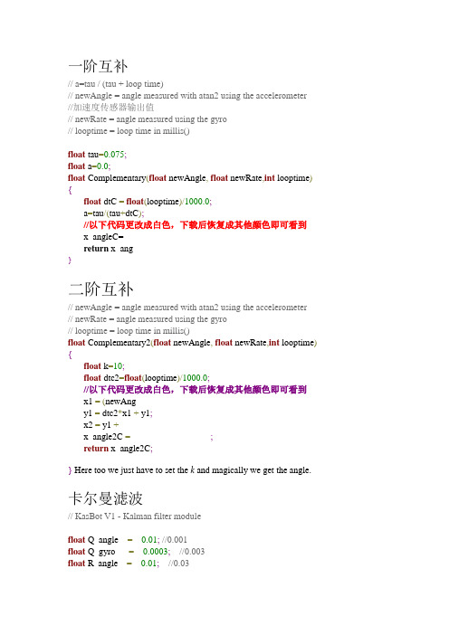
加速度计与陀螺仪融合一阶互补滤波、二阶互补滤波、卡尔曼滤波核心程序
一阶互补// a=tau / (tau + loop time)// newAngle = angle measured with atan2 using the accelerometer//加速度传感器输出值// newRate = angle measured using the gyro// looptime = loop time in millis()float tau=0.075;float a=0.0;float Complementary(float newAngle,float newRate,int looptime) {float dtC =float(looptime)/1000.0;a=tau/(tau+dtC);//以下代码更改成白色,下载后恢复成其他颜色即可看到x_angleC= a* (x_angleC + newRate * dtC) + (1-a) * (newAngle);return x_ang leC;}二阶互补// newAngle = angle measured with atan2 using the accelerometer// newRate = angle measured using the gyro// looptime = loop time in millis()float Complementary2(float newAngle,float newRate,int looptime) {float k=10;float dtc2=float(looptime)/1000.0;//以下代码更改成白色,下载后恢复成其他颜色即可看到x1 =(newAng le - x_angle2C)*k*k;y1 = dtc2*x1 + y1;x2 = y1 + (newAngle - x_angle2C)*2*k + newRate;x_angle2C =dtc2*x2 + x_angle2C;return x_angle2C;} Here too we just have to set the k and magically we get the angle.卡尔曼滤波// KasBot V1 - Kalman filter modulefloat Q_angle =0.01;//0.001float Q_gyro =0.0003;//0.003float R_angle =0.01;//0.03float x_bias =0;float P_00 =0, P_01 =0, P_10 =0, P_11 =0;float y, S;float K_0, K_1;// newAngle = angle measured with atan2 using the accelerometer // newRate = angle measured using the gyro// looptime = loop time in millis()float kalmanCalculate(float newAngle,float newRate,int looptime) {float dt =float(looptime)/1000;x_angle += dt *(newRate - x_bias);//以下代码更改成白色,下载后恢复成其他颜色即可看到P_00 +=- dt * (P_10 + P_01) + Q_angle * dt;P_01 +=- dt * P_11;P_10 +=- dt * P_11;P_11 +=+ Q_gyro * dt;y = newAngle - x_angle;S = P_00 + R_angle;K_0 = P_00 / S;K_1 = P_10 / S;x_angle +=K_0 * y;x_bias +=K_1 * y;P_00 -= K_0 * P_00;P_01 -= K_0 * P_01;P_10 -= K_1 * P_00;P_11 -= K_1 * P_01;return x_angle;} To get the answer, you have to set 3 parameters: Q_angle, R_angle,R_gyro.详细卡尔曼滤波/* -*- indent-tabs-mode:T; c-basic-offset:8; tab-width:8; -*- vi: set ts=8:* $Id: tilt.c,v 1.1 2003/07/09 18:23:29 john Exp $** 1 dimensional tilt sensor using a dual axis accelerometer* and single axis angular rate gyro. The two sensors are fused* via a two state Kalman filter, with one state being the angle* and the other state being the gyro bias.* Gyro bias is automatically tracked by the filter. This seems* like magic.** Please note that there are lots of comments in the functions and* in blocks before the functions. Kalman filtering is an already complex* subject, made even more so by extensive hand optimizations to the C code* that implements the filter. I've tried to make an effort of explaining* the optimizations, but feel free to send mail to the mailing list,* autopilot-devel@, with questions about this code.*** (c) 2003 Trammell Hudson <hudson@>**************** This file is part of the autopilot onboard code package.** Autopilot is free software; you can redistribute it and/or modify* it under the terms of the GNU General Public License as published by* the Free Software Foundation; either version 2 of the License, or* (at your option) any later version.** Autopilot is distributed in the hope that it will be useful,* but WITHOUT ANY W ARRANTY; without even the implied warranty of* MERCHANTABILITY or FITNESS FOR A PARTICULAR PURPOSE. See the * GNU General Public License for more details.** You should have received a copy of the GNU General Public License* along with Autopilot; if not, write to the Free Software* Foundation, Inc., 59 Temple Place, Suite 330, Boston, MA 02111-1307 USA **/#include <math.h>/** Our update rate. This is how often our state is updated with* gyro rate measurements. For now, we do it every time an* 8 bit counter running at CLK/1024 expires. You will have to* change this value if you update at a different rate.*/static const float dt = ( 1024.0 * 256.0 ) / 8000000.0;/** Our covariance matrix. This is updated at every time step to* determine how well the sensors are tracking the actual state.*/static float P[2][2] = {{ 1, 0 },{ 0, 1 },};/** Our two states, the angle and the gyro bias. As a byproduct of computing * the angle, we also have an unbiased angular rate available. These are* read-only to the user of the module.*/float angle;float q_bias;float rate;/** R represents the measurement covariance noise. In this case,* it is a 1x1 matrix that says that we expect 0.3 rad jitter* from the accelerometer.*/static const float R_angle = 0.3;/** Q is a 2x2 matrix that represents the process covariance noise.* In this case, it indicates how much we trust the acceleromter* relative to the gyros.*/static const float Q_angle = 0.001;static const float Q_gyro = 0.003;/** state_update is called every dt with a biased gyro measurement* by the user of the module. It updates the current angle and* rate estimate.** The pitch gyro measurement should be scaled into real units, but* does not need any bias removal. The filter will track the bias.** Our state vector is:** X = [ angle, gyro_bias ]** It runs the state estimation forward via the state functions:** Xdot = [ angle_dot, gyro_bias_dot ]** angle_dot = gyro - gyro_bias* gyro_bias_dot = 0** And updates the covariance matrix via the function:** Pdot = A*P + P*A' + Q** A is the Jacobian of Xdot with respect to the states:** A = [ d(angle_dot)/d(angle) d(angle_dot)/d(gyro_bias) ]* [ d(gyro_bias_dot)/d(angle) d(gyro_bias_dot)/d(gyro_bias) ]** = [ 0 -1 ]* [ 0 0 ]** Due to the small CPU available on the microcontroller, we've* hand optimized the C code to only compute the terms that are* explicitly non-zero, as well as expanded out the matrix math* to be done in as few steps as possible. This does make it harder* to read, debug and extend, but also allows us to do this with* very little CPU time.*/voidstate_update( const float q_m /* Pitch gyro measurement */) {/* Unbias our gyro */const float q = q_m - q_bias;/** Compute the derivative of the covariance matrix** Pdot = A*P + P*A' + Q** We've hand computed the expansion of A = [ 0 -1, 0 0 ] multiplied* by P and P multiplied by A' = [ 0 0, -1, 0 ]. This is then added * to the diagonal elements of Q, which are Q_angle and Q_gyro.*/const float Pdot[2 * 2] = {Q_angle - P[0][1] - P[1][0], /* 0,0 */- P[1][1], /* 0,1 */- P[1][1], /* 1,0 */Q_gyro /* 1,1 */};/* Store our unbias gyro estimate */rate = q;/** Update our angle estimate* angle += angle_dot * dt* += (gyro - gyro_bias) * dt* += q * dt*/angle += q * dt;/* Update the covariance matrix */P[0][0] += Pdot[0] * dt;P[0][1] += Pdot[1] * dt;P[1][0] += Pdot[2] * dt;P[1][1] += Pdot[3] * dt;}/** kalman_update is called by a user of the module when a new* accelerometer measurement is available. ax_m and az_m do not * need to be scaled into actual units, but must be zeroed and have* the same scale.** This does not need to be called every time step, but can be if* the accelerometer data are available at the same rate as the* rate gyro measurement.** For a two-axis accelerometer mounted perpendicular to the rotation * axis, we can compute the angle for the full 360 degree rotation* with no linearization errors by using the arctangent of the two* readings.** As commented in state_update, the math here is simplified to* make it possible to execute on a small microcontroller with no* floating point unit. It will be hard to read the actual code and* see what is happening, which is why there is this extensive* comment block.** The C matrix is a 1x2 (measurements x states) matrix that* is the Jacobian matrix of the measurement value with respect* to the states. In this case, C is:** C = [ d(angle_m)/d(angle) d(angle_m)/d(gyro_bias) ]* = [ 1 0 ]** because the angle measurement directly corresponds to the angle* estimate and the angle measurement has no relation to the gyro* bias.*/voidkalman_update(const float ax_m, /* X acceleration */const float az_m /* Z acceleration */){/* Compute our measured angle and the error in our estimate *///以下代码更改成白色,下载后恢复成其他颜色即可看到const float angle_m = atan2( -az_m, ax_m );const float angle_err = angle_m - angle;/** C_0 shows how the state measurement directly relates to* the state estimate.** The C_1 shows that the state measurement does not relate* to the gyro bias estimate. We don't actually use this, so* we comment it out.*/const float C_0 = 1;/* const float C_1 = 0; *//** PCt<2,1> = P<2,2> * C'<2,1>, which we use twice. This makes * it worthwhile to precompute and store the two values.* Note that C[0,1] = C_1 is zero, so we do not compute that* term.*/const float PCt_0 = C_0 * P[0][0]; /* + C_1 * P[0][1] = 0 */ const float PCt_1 = C_0 * P[1][0]; /* + C_1 * P[1][1] = 0 *//** Compute the error estimate. From the Kalman filter paper:** E = C P C' + R** Dimensionally,** E<1,1> = C<1,2> P<2,2> C'<2,1> + R<1,1>** Again, note that C_1 is zero, so we do not compute the term.*/const float E =R_angle+ C_0 * PCt_0/* + C_1 * PCt_1 = 0 */;/** Compute the Kalman filter gains. From the Kalman paper:** K = P C' inv(E)** Dimensionally:** K<2,1> = P<2,2> C'<2,1> inv(E)<1,1>** Luckilly, E is <1,1>, so the inverse of E is just 1/E.*/const float K_0 = PCt_0 / E;const float K_1 = PCt_1 / E;/** Update covariance matrix. Again, from the Kalman filter paper: ** P = P - K C P** Dimensionally:** P<2,2> -= K<2,1> C<1,2> P<2,2>** We first compute t<1,2> = C P. Note that:** t[0,0] = C[0,0] * P[0,0] + C[0,1] * P[1,0]** But, since C_1 is zero, we have:** t[0,0] = C[0,0] * P[0,0] = PCt[0,0]** This saves us a floating point multiply.*/const float t_0 = PCt_0; /* C_0 * P[0][0] + C_1 * P[1][0] */ const float t_1 = C_0 * P[0][1]; /* + C_1 * P[1][1] = 0 */P[0][0] -= K_0 * t_0;P[0][1] -= K_0 * t_1;P[1][0] -= K_1 * t_0;P[1][1] -= K_1 * t_1;/** Update our state estimate. Again, from the Kalman paper:** X += K * err** And, dimensionally,** X<2> = X<2> + K<2,1> * err<1,1>** err is a measurement of the difference in the measured state* and the estimate state. In our case, it is just the difference* between the two accelerometer measured angle and our estimated * angle.*/angle += K_0 * angle_err;q_bias += K_1 * angle_err;}。
卡尔曼滤波算法的程序实现和推导过程

卡尔曼滤波算法的程序实现和推导过程卡尔曼滤波算法的程序实现和推导过程---蒋海林(QQ:280586940)---卡尔曼滤波算法由匈牙利裔美国数学家鲁道夫·卡尔曼(Rudolf Emil Kalman)创立,这个数学家特么牛逼,1930年出生,现在还能走能跳,吃啥啥麻麻香,但他的卡尔曼滤波算法已经广泛应用在航空航天,导弹发射,卫星在轨运行等很多高大上的应用中。
让我们一边膜拜一边上菜吧,下面就是卡尔曼滤波算法的经典程序,说是经典,因为能正常运行的程序都长得差不多,在此向原作者致敬。
看得懂的,帮我纠正文中的错误;不太懂的,也不要急,让我慢慢道来。
最后希望广大朋友转载时,能够保留我的联系方式,一则方便后续讨论共同进步,二则支持奉献支持正能量。
void Kalman_Filter(float Gyro,float Accel)///角速度,加速度{///陀螺仪积分角度(先验估计)Angle_Final = Angle_Final + (Gyro - Q_bias) * dt;///先验估计误差协方差的微分Pdot[0] = Q_angle - PP[0][1] - PP[1][0];Pdot[1] = - PP[1][1];Pdot[2] = - PP[1][1];Pdot[3] = Q_gyro;///先验估计误差协方差的积分PP[0][0] += Pdot[0] * dt;PP[0][1] += Pdot[1] * dt;PP[1][0] += Pdot[2] * dt;PP[1][1] += Pdot[3] * dt;///计算角度偏差Angle_err = Accel - Angle_Final;///卡尔曼增益计算PCt_0 = C_0 * PP[0][0];PCt_1 = C_0 * PP[1][0];E = R_angle + C_0 * PCt_0;K_0 = PCt_0 / E;K_1 = PCt_1 / E;///后验估计误差协方差计算t_0 = PCt_0;t_1 = C_0 * PP[0][1];PP[0][0] -= K_0 * t_0;PP[0][1] -= K_0 * t_1;PP[1][0] -= K_1 * t_0;PP[1][1] -= K_1 * t_1;Angle_Final += K_0 * Angle_err; ///后验估计最优角度值Q_bias += K_1 * Angle_err; ///更新最优估计值的偏差Gyro_Final = Gyro - Q_bias; ///更新最优角速度值}我们先把卡尔曼滤波的5个方程贴上来:X(k|k-1)=A X(k-1|k-1)+B U(k) ……… (1)//先验估计P(k|k-1)=A P(k-1|k-1) A ’+Q ……… (2)//协方差矩阵的预测Kg(k)= P(k|k-1) H ’ / (H P(k|k-1) H ’ + R) ……… (3)//计算卡尔曼增益 X(k|k)= X(k|k-1)+Kg(k) (Z(k) - H X(k|k-1)) ……… (4)通过卡尔曼增益进行修正 P(k|k)=(I-Kg(k) H )P(k|k-1) ……… (5)//更新协方差阵这5个方程比较抽象,下面我们就来把这5个方程和上面的程序对应起来。
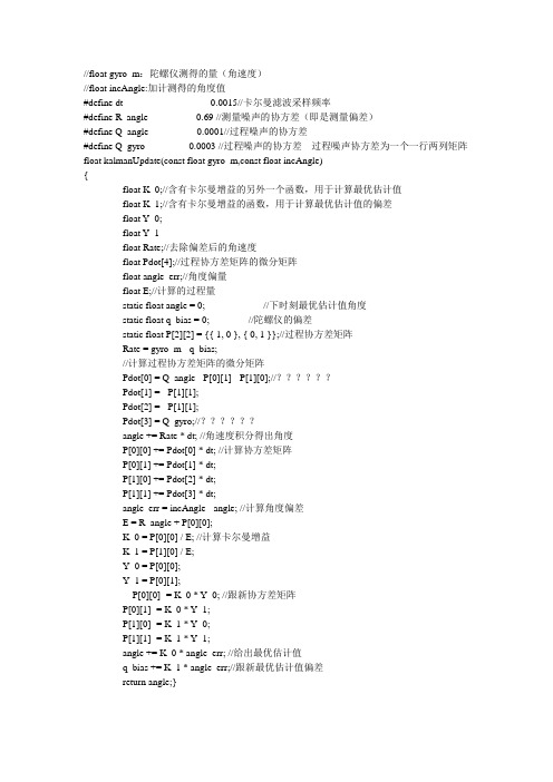
陀螺仪+加速度计卡尔曼
//float gyro_m:陀螺仪测得的量(角速度)//float incAngle:加计测得的角度值#define dt 0.0015//卡尔曼滤波采样频率#define R_angle 0.69 //测量噪声的协方差(即是测量偏差)#define Q_angle 0.0001//过程噪声的协方差#define Q_gyro 0.0003 //过程噪声的协方差过程噪声协方差为一个一行两列矩阵float kalmanUpdate(const float gyro_m,const float incAngle){float K_0;//含有卡尔曼增益的另外一个函数,用于计算最优估计值float K_1;//含有卡尔曼增益的函数,用于计算最优估计值的偏差float Y_0;float Y_1float Rate;//去除偏差后的角速度float Pdot[4];//过程协方差矩阵的微分矩阵float angle_err;//角度偏量float E;//计算的过程量static float angle = 0; //下时刻最优估计值角度static float q_bias = 0; //陀螺仪的偏差static float P[2][2] = {{ 1, 0 }, { 0, 1 }};//过程协方差矩阵Rate = gyro_m - q_bias;//计算过程协方差矩阵的微分矩阵Pdot[0] = Q_angle - P[0][1] - P[1][0];//??????Pdot[1] = - P[1][1];Pdot[2] = - P[1][1];Pdot[3] = Q_gyro;//??????angle += Rate * dt; //角速度积分得出角度P[0][0] += Pdot[0] * dt; //计算协方差矩阵P[0][1] += Pdot[1] * dt;P[1][0] += Pdot[2] * dt;P[1][1] += Pdot[3] * dt;angle_err = incAngle - angle; //计算角度偏差E = R_angle + P[0][0];K_0 = P[0][0] / E; //计算卡尔曼增益K_1 = P[1][0] / E;Y_0 = P[0][0];Y_1 = P[0][1];P[0][0] -= K_0 * Y_0; //跟新协方差矩阵P[0][1] -= K_0 * Y_1;P[1][0] -= K_1 * Y_0;P[1][1] -= K_1 * Y_1;angle += K_0 * angle_err; //给出最优估计值q_bias += K_1 * angle_err;//跟新最优估计值偏差return angle;}加速度模块角度计算:如果传感器x 轴朝下,y 轴朝前那竖直方向弧度计算公式为:angle = atan2(y, z) //结果以弧度表示并介于-pi 到pi 之间(不包括-pi)如果要换算成具体角度:angle = atan2(y, z) * (180/3.14)陀螺仪角度计算:式中angle(n)为陀螺仪采样到第n次的角度值;angle(n-1)为陀螺仪第n-1次采样时的角度值;gyron为陀螺仪的第n次采样得到的瞬时角速率值;dt为运行一遍所用时间;angle_n += gyro(n) * dt //积分计算卡尔曼滤波网上找的kalman滤波,具体代码如下static const float dt = 0.02;static float P[2][2] = {{ 1, 0 }, { 0, 1 }};float angle;float q_bias;float rate;static const float R_angle = 0.5 ;static const float Q_angle = 0.001;static const float Q_gyro = 0.003;float stateUpdate(const float gyro_m){float q;float Pdot[4];q = gyro_m - q_bias;Pdot[0] = Q_angle - P[0][1] - P[1][0]; /* 0,0 */Pdot[1] = - P[1][1]; /* 0,1 */Pdot[2] = - P[1][1]; /* 1,0 */Pdot[3] = Q_gyro; /* 1,1 */rate = q;angle += q * dt;P[0][0] += Pdot[0] * dt;P[0][1] += Pdot[1] * dt;P[1][0] += Pdot[2] * dt;P[1][1] += Pdot[3] * dt;return angle;}float kalmanUpdate(const float incAngle){float angle_m = incAngle;float angle_err = angle_m - angle;float h_0 = 1;const float PHt_0 = h_0*P[0][0]; /* + h_1*P[0][1] = 0*/ const float PHt_1 = h_0*P[1][0]; /* + h_1*P[1][1] = 0*/ float E = R_angle +(h_0 * PHt_0);float K_0 = PHt_0 / E;float K_1 = PHt_1 / E;float Y_0 = PHt_0; /*h_0 * P[0][0]*/float Y_1 = h_0 * P[0][1];P[0][0] -= K_0 * Y_0;P[0][1] -= K_0 * Y_1;P[1][0] -= K_1 * Y_0;P[1][1] -= K_1 * Y_1;angle += K_0 * angle_err;q_bias += K_1 * angle_err;return angle;}。
imu单元参数
IMU单元参数什么是IMU单元?IMU(惯性测量单元)是一种集成了加速度计、陀螺仪和磁力计的传感器单元。
它可以测量物体的加速度、角速度和磁场强度。
IMU单元通常用于航空航天、自动驾驶、运动追踪等领域。
IMU单元的参数IMU单元的参数可以分为硬件参数和软件参数两个方面。
硬件参数1.加速度计量程:加速度计量程指的是加速度计可以测量的最大加速度范围。
常见的量程有±2g、±4g、±8g、±16g等。
较大的量程意味着可以测量更大范围的加速度。
2.加速度计分辨率:加速度计分辨率是指加速度计可以测量的最小加速度变化量。
它决定了加速度计的精度。
一般以m/s²为单位。
3.陀螺仪量程:陀螺仪量程指的是陀螺仪可以测量的最大角速度范围。
常见的量程有±250°/s、±500°/s、±1000°/s、±2000°/s等。
4.陀螺仪分辨率:陀螺仪分辨率是指陀螺仪可以测量的最小角速度变化量。
它决定了陀螺仪的精度。
一般以°/s为单位。
5.磁力计量程:磁力计量程指的是磁力计可以测量的最大磁场强度范围。
常见的量程有±2.5、±4.7、±5.6、±8.1等。
6.磁力计分辨率:磁力计分辨率是指磁力计可以测量的最小磁场强度变化量。
它决定了磁力计的精度。
一般以高斯为单位。
软件参数1.数据输出频率:数据输出频率指的是IMU单元每秒钟向外部设备发送数据的次数。
它决定了数据的实时性。
常见的输出频率有100Hz、200Hz、400Hz等。
2.数据格式:数据格式指的是IMU单元输出数据的格式。
常见的格式有加速度、角速度和磁场强度的原始数据,以及经过滤波和姿态解算处理后的欧拉角、四元数等。
3.滤波算法:滤波算法用于对原始数据进行处理,去除噪声和干扰,提高数据的可靠性和精度。
常见的滤波算法有卡尔曼滤波、互补滤波等。
卡尔曼滤波程序

最佳线性滤波理论起源于40年代美国科学家Wiener和前苏联科学家Kолмогоров等人的研究工作,后人统称为维纳滤波理论。
从理论上说,维纳滤波的最大缺点是必须用到无限过去的数据,不适用于实时处理。
为了克服这一缺点,60年代Kalman把状态空间模型引入滤波理论,并导出了一套递推估计算法,后人称之为卡尔曼滤波理论。
卡尔曼滤波是以最小均方误差为估计的最佳准则,来寻求一套递推估计的算法,其基本思想是:采用信号与噪声的状态空间模型,利用前一时刻地估计值和现时刻的观测值来更新对状态变量的估计,求出现时刻的估计值。
它适合于实时处理和计算机运算。
现设线性时变系统的离散状态防城和观测方程为:X(k) = F(k,k-1)·X(k-1)+T(k,k-1)·U(k-1)Y(k) = H(k)·X(k)+N(k)其中X(k)和Y(k)分别是k时刻的状态矢量和观测矢量F(k,k-1)为状态转移矩阵U(k)为k时刻动态噪声T(k,k-1)为系统控制矩阵H(k)为k时刻观测矩阵N(k)为k时刻观测噪声则卡尔曼滤波的算法流程为:1.预估计X(k)^= F(k,k-1)·X(k-1)2.计算预估计协方差矩阵C(k)^=F(k,k-1)×C(k)×F(k,k-1)'+T(k,k-1)×Q(k)×T(k,k-1)'Q(k) = U(k)×U(k)'3.计算卡尔曼增益矩阵K(k) = C(k)^×H(k)'×[H(k)×C(k)^×H(k)'+R(k)]^(-1)R(k) = N(k)×N(k)'4.更新估计X(k)~=X(k)^+K(k)×[Y(k)-H(k)×X(k)^]5.计算更新后估计协防差矩阵C(k)~ = [I-K(k)×H(k)]×C(k)^×[I-K(k)×H(k)]'+K(k)×R(k)×K(k)' 6.X(k+1) = X(k)~C(k+1) = C(k)~重复以上步骤其c语言实现代码如下:#include "stdlib.h"#include "rinv.c"int lman(n,m,k,f,q,r,h,y,x,p,g)int n,m,k;double f[],q[],r[],h[],y[],x[],p[],g[];{ int i,j,kk,ii,l,jj,js;double *e,*a,*b;e=malloc(m*m*sizeof(double));l=m;if (l<n) l=n;a=malloc(l*l*sizeof(double));b=malloc(l*l*sizeof(double));for (i=0; i<=n-1; i++)for (j=0; j<=n-1; j++){ ii=i*l+j; a[ii]=0.0;for (kk=0; kk<=n-1; kk++)a[ii]=a[ii]+p[i*n+kk]*f[j*n+kk];}for (i=0; i<=n-1; i++)for (j=0; j<=n-1; j++){ ii=i*n+j; p[ii]=q[ii];for (kk=0; kk<=n-1; kk++)p[ii]=p[ii]+f[i*n+kk]*a[kk*l+j];}for (ii=2; ii<=k; ii++){ for (i=0; i<=n-1; i++)for (j=0; j<=m-1; j++){ jj=i*l+j; a[jj]=0.0;for (kk=0; kk<=n-1; kk++)}for (i=0; i<=m-1; i++)for (j=0; j<=m-1; j++){ jj=i*m+j; e[jj]=r[jj];for (kk=0; kk<=n-1; kk++)e[jj]=e[jj]+h[i*n+kk]*a[kk*l+j];}js=rinv(e,m);if (js==0){ free(e); free(a); free(b); return(js);}for (i=0; i<=n-1; i++)for (j=0; j<=m-1; j++){ jj=i*m+j; g[jj]=0.0;for (kk=0; kk<=m-1; kk++)g[jj]=g[jj]+a[i*l+kk]*e[j*m+kk];}for (i=0; i<=n-1; i++){ jj=(ii-1)*n+i; x[jj]=0.0;for (j=0; j<=n-1; j++)x[jj]=x[jj]+f[i*n+j]*x[(ii-2)*n+j];}for (i=0; i<=m-1; i++){ jj=i*l; b[jj]=y[(ii-1)*m+i];for (j=0; j<=n-1; j++)b[jj]=b[jj]-h[i*n+j]*x[(ii-1)*n+j];}for (i=0; i<=n-1; i++){ jj=(ii-1)*n+i;for (j=0; j<=m-1; j++)x[jj]=x[jj]+g[i*m+j]*b[j*l];}if (ii<k){ for (i=0; i<=n-1; i++)for (j=0; j<=n-1; j++){ jj=i*l+j; a[jj]=0.0;for (kk=0; kk<=m-1; kk++)a[jj]=a[jj]-g[i*m+kk]*h[kk*n+j];if (i==j) a[jj]=1.0+a[jj];}for (i=0; i<=n-1; i++)for (j=0; j<=n-1; j++){ jj=i*l+j; b[jj]=0.0;for (kk=0; kk<=n-1; kk++)}for (i=0; i<=n-1; i++)for (j=0; j<=n-1; j++){ jj=i*l+j; a[jj]=0.0;for (kk=0; kk<=n-1; kk++)a[jj]=a[jj]+b[i*l+kk]*f[j*n+kk];}for (i=0; i<=n-1; i++)for (j=0; j<=n-1; j++){ jj=i*n+j; p[jj]=q[jj];for (kk=0; kk<=n-1; kk++)p[jj]=p[jj]+f[i*n+kk]*a[j*l+kk];}}}free(e); free(a); free(b);return(js);}C++实现代码如下:============================kalman.h================= ===============// kalman.h: interface for the kalman class.////////////////////////////////////////////////////////////////////////#if !defined(AFX_KALMAN_H__ED3D740F_01D2_4616_8B74_8BF57636F2C0__IN CLUDED_)#define AFX_KALMAN_H__ED3D740F_01D2_4616_8B74_8BF57636F2C0__INCLU DED_#if _MSC_VER > 1000#pragma once#endif// _MSC_VER > 1000#include <math.h>#include "cv.h"class kalman{public:void init_kalman(int x,int xv,int y,int yv);CvKalman* cvkalman;CvMat* state;CvMat* process_noise;CvMat* measurement;const CvMat* prediction;CvPoint2D32f get_predict(float x, float y);kalman(int x=0,int xv=0,int y=0,int yv=0);//virtual ~kalman();};#endif// !defined(AFX_KALMAN_H__ED3D740F_01D2_4616_8B74_8BF57636F2C 0__INCLUDED_)============================kalman.cpp=============== =================#include "kalman.h"#include <stdio.h>/* tester de printer toutes les valeurs des vecteurs*//* tester de changer les matrices du noises *//* replace state by cvkalman->state_post ??? */CvRandState rng;const double T = 0.1;kalman::kalman(int x,int xv,int y,int yv){cvkalman = cvCreateKalman( 4, 4, 0 );state = cvCreateMat( 4, 1, CV_32FC1 );process_noise = cvCreateMat( 4, 1, CV_32FC1 );measurement = cvCreateMat( 4, 1, CV_32FC1 );int code = -1;/* create matrix data */const float A[] = {1, T, 0, 0,0, 1, 0, 0,0, 0, 1, T,0, 0, 0, 1};const float H[] = {1, 0, 0, 0,0, 0, 0, 0,0, 0, 1, 0,0, 0, 0, 0};const float P[] = {pow(320,2), pow(320,2)/T, 0, 0,pow(320,2)/T, pow(320,2)/pow(T,2), 0, 0, 0, 0, pow(240,2), pow(240,2)/T,0, 0, pow(240,2)/T, pow(240,2)/pow(T,2)};const float Q[] = {pow(T,3)/3, pow(T,2)/2, 0, 0,pow(T,2)/2, T, 0, 0,0, 0, pow(T,3)/3, pow(T,2)/2,0, 0, pow(T,2)/2, T};const float R[] = {1, 0, 0, 0,0, 0, 0, 0,0, 0, 1, 0,0, 0, 0, 0};cvRandInit( &rng, 0, 1, -1, CV_RAND_UNI ); cvZero( measurement );cvRandSetRange( &rng, 0, 0.1, 0 );rng.disttype = CV_RAND_NORMAL;cvRand( &rng, state );memcpy( cvkalman->transition_matrix->data.fl, A, sizeof(A));memcpy( cvkalman->measurement_matrix->data.fl, H, sizeof(H));memcpy( cvkalman->process_noise_cov->data.fl, Q, sizeof(Q));memcpy( cvkalman->error_cov_post->data.fl, P, sizeof(P));memcpy( cvkalman->measurement_noise_cov->data.fl, R, sizeof(R));//cvSetIdentity( cvkalman->process_noise_cov, cvRealScalar(1e-5) );//cvSetIdentity( cvkalman->error_cov_post, cvRealScalar(1));//cvSetIdentity( cvkalman->measurement_noise_cov, cvRealScalar(1e-1) );/* choose initial state */state->data.fl[0]=x;state->data.fl[1]=xv;state->data.fl[2]=y;state->data.fl[3]=yv;cvkalman->state_post->data.fl[0]=x;cvkalman->state_post->data.fl[1]=xv;cvkalman->state_post->data.fl[2]=y;cvkalman->state_post->data.fl[3]=yv;cvRandSetRange( &rng, 0, sqrt(cvkalman->process_noise_cov->data.fl[0]), 0 ); cvRand( &rng, process_noise );}CvPoint2D32f kalman::get_predict(float x, float y){/* update state with current position */state->data.fl[0]=x;state->data.fl[2]=y;/* predict point position *//* x'k=A鈥鈥P'k=A鈥-1*AT + Q */cvRandSetRange( &rng, 0, sqrt(cvkalman->measurement_noise_cov->data.fl [0]), 0 );cvRand( &rng, measurement );/* xk=A?xk-1+B?uk+wk */cvMatMulAdd( cvkalman->transition_matrix, state, process_noise, cvkalman->state_post );/* zk=H?xk+vk */cvMatMulAdd( cvkalman->measurement_matrix, cvkalman->state_post, meas urement, measurement );/* adjust Kalman filter state *//* Kk=P'k鈥鈥?H鈥鈥-1xk=x'k+Kk鈥?zk-H鈥Pk=(I-Kk鈥鈥 */cvKalmanCorrect( cvkalman, measurement );float measured_value_x = measurement->data.fl[0];float measured_value_y = measurement->data.fl[2];const CvMat* prediction = cvKalmanPredict( cvkalman, 0 );float predict_value_x = prediction->data.fl[0];float predict_value_y = prediction->data.fl[2];return(cvPoint2D32f(predict_value_x,predict_value_y));}void kalman::init_kalman(int x,int xv,int y,int yv){state->data.fl[0]=x;state->data.fl[1]=xv;state->data.fl[2]=y;state->data.fl[3]=yv;cvkalman->state_post->data.fl[0]=x;cvkalman->state_post->data.fl[1]=xv;cvkalman->state_post->data.fl[2]=y;cvkalman->state_post->data.fl[3]=yv;}。
