tdc3000 LCN手册
TDS3000C系列数字振荡器数据手册说明书

RM3000TDS3012CENCORE TDS3TMT TDS3VID TDS3012CENCOREDigital Phosphor OscilloscopesTDS3000C Series DatasheetThe TDS3000C Series provides you with the performance you need at a price you can afford. Bandwidths range from 100 MHz to 500 MHz, with up to 5 GS/s sample rates for accurate representation of your signal.Key performance specifications100 MHz, 300 MHz, and 500 MHz bandwidth models2 or 4 analog channel modelsSample rates up to 5 GS/s real time on all channels10k record length on all channels3,600 wfms/s continuous waveform capture rate Suite of advanced triggersKey featuresFront-panel USB host port for easy storage and transfer ofmeasurement data25 automatic measurementsFFT standardMultiple language user interfaceWaveAlert ®automatic waveform anomaly detectionTekProbe ® interface supports active, differential, and current probes for automatic scaling and unitsPortable designLightweight design (only 7 lb./3.2 kg) for easy transportOptional internal battery operation provides up to three hours without line powerApplication modules for specialized analysisAdvanced analysis moduleLimit testing moduleTelecommunications mask testing module Extended video moduleApplicationsDigital design and debugVideo installation and servicePower supply designEducation and trainingTelecommunications mask testingManufacturing test General bench testingDPOs provide greater level of insight into complex signalsThe TDS3000C Series offers fast waveform capture rates on a continuous basis that save you time by quickly revealing the nature of faults, so advanced triggers can be applied to isolate them.Real-time intensity grading highlights the details about the history of a signal's activity, making it easier to understand the characteristics of the waveforms you've captured. Unlike other comparable oscilloscopes, thehistory remains even after the acquisition has been stopped. 1Quickly debug and characterize signals with DRT sampling technology and sin (x)/x interpolationThe TDS3000C Series combines unique digital real-time (DRT) sampling technology with sin(x)/x interpolation to allow you to accurately characterize a wide range of signal types on all channels simultaneously. With the TDS3000C Series there is no change in sampling rate when additional channels are turned on, unlike other comparable oscilloscopes. This sampling technology makes it possible to capture high-frequency information, such as glitches and edge anomalies, that elude other oscilloscopes in its class, while sin(x)/x interpolation ensures precisereconstruction of each waveform.Look for unintentional circuit noise with the TDS3000C series’ FFT capability.Custom video triggering allows the TDS3000C Series to trigger on standards such asRS-343 (26.2 kHz scan rate).The TDS3000C Series provides breakthrough test speeds for telecommunications line card testing. The telecom QUICKMENU puts all the commonly used telecom test functions on a single menu.Easy to setup and useWhen working under tight deadlines, you need your oscilloscope to be intuitive; you want to minimize time spent learning and relearning how to use it. The TDS3000C Series oscilloscopes help reduce your learning curve. Simple navigation and dedicated front-panel controls get you to where you want to be quickly, so that you spend less time learning andmore time on the task at hand.The TDS3000C series with the TDS3LIM module is ideal for manufacturing test applications where fast Go/No-Go decisions are required.Datasheet2 WaveAlert waveform anomaly detection alerts you to any waveform that deviates fromthe “normal” input such as the glitch on channel 2.Easily transfer, document, and analyze data on your PC.Simple documentation and analysisThe TDS3000C Series comes equipped with a USB host port so you can easily store and transfer measurement information to your PC.OpenChoice ®PC Communication Software allows you to simply pull screen images and waveform data into a standalone desktop application or directly into Microsoft Word and Excel.If you prefer not to use a PC for analysis, the TDS3000C Series comes standard with 25 automatic measurements, waveform add, subtract, divide,and multiply math functions, and Fast Fourier Transform (FFT). Unlike other comparable oscilloscopes, the TDS3000C Series math andmeasurement allows you to use the full acquisition record length or isolate a specific occurrence within an acquisition.Instrument controlUtilizing the built-in ethernet port, e*Scope web-based remote control allows you to a control TDS3000C series oscilloscope from anywhere,using the internet and your PC.Work where you need toThe TDS3000C Series packs the power of a DPO in a compact design that is only 5.9 in. (149 mm) deep, freeing up valuable benchtop space. And when you need to move your oscilloscope to another lab, its portable 7 lb.(3.2 kg) design makes for easy transport.If your work demands even more mobility, then the optional battery packwill give you up to three hours of operation without line power.TDS3BATC provides you with up to three hours of portable battery operation.TDS3000C Series Digital Phosphor Oscilloscopes 3SpecificationsAll specifications are guaranteed unless noted otherwise. All specifications apply to all models unless noted otherwise.Vertical systemHardware bandwidth limitsInput coupling AC, DC, GNDInput impedance 1 MΩ in parallel with 13 pF or 50 ΩInput sensitivity range1 MΩ 1 mV/div to 10 V/div 50 Ω 1 mV/div to 1 V/div Vertical resolution 9 bits Maximum input voltage1 MΩ150 V RMS with peaks at ≤400 V 50 Ω 5 V RMS with peaks at ≤30 V DC gain accuracy ±2%Position range±5 divHorizontal systemSeconds/division rangeTime base accuracy±20 ppm over any 1 ms time intervalDatasheet4 TDS3000C Series Digital Phosphor Oscilloscopes Trigger systemTrigger modes Auto (supports Roll Mode for 40 ms/div and slower), Normal, Single SequenceB trigger Trigger after time or eventsTrigger after time range13.2 ns to 50 sTrigger after events range 1 to 9,999,999 eventsTrigger typesEdge Conventional level-driven trigger. Positive or negative slope on any channel. Coupling selections: AC, DC, Noise Reject, HFReject, LF RejectVideo Trigger on all lines or individual lines, odd/even or all fields on NTSC, PAL, SECAMExtended video Trigger on specific lines in broadcast and non-broadcast (custom) standards and on analog HDTV formats (1080i, 1080p, 720p,480p). Requires TDS3VID application modulePulse width (or glitch)Trigger on a pulse width <, >, =, ≠ to a selectable time limit ranging from 39.6 ns to 50 sRunt Trigger on a pulse that crosses one threshold but fails to cross a second threshold before crossing the first againRise/fall time Trigger on pulse edge rates that are either faster or slower than a set rate. Edges can be rising, falling, or eitherPattern Specifies AND, OR, NAND, NOR when true or false for a specific timeState Any logic state. Triggerable on rising or falling edge of a clock. Logic triggers can be used on combinations of 2 inputs (not 4) Comm Provides isolated pulse triggering required to perform DS1/DS3 telecommunications mask testing per ANSI T1.102 standard.Requires TDS3TMT application moduleAlternate Sequentially uses each active channel as a trigger sourceAcquisition systemDPO Captures and displays complex waveforms, random events and subtle patterns in actual signal behavior. DPOs provide3 dimensions of signal information in real time: Amplitude, time, and the distribution of amplitude over timeSample Sample data onlyAverage Waveform averaged, selectable from 2 to 512Envelope Min-max values acquired over one or more acquisitionsPeak detect High-frequency and random glitch capture. Captures glitches as narrow as 1 ns (typical) using acquisition hardware at all timebase settingsWaveAlert®Monitors the incoming signals on all channels and alerts the user to any waveform that deviates from the normal waveform beingacquiredSingle sequence Use the Single Sequence button to capture a single triggered acquisition sequence at a time 5DatasheetWaveform measurementsCursors Amplitude, timeAutomatic measurements Display any four measurements from any combination of waveforms. Or display all measurements with measurement snapshotfeature. Measurements include Period, Frequency, +Width, -Width, Rise time, Fall time, +Duty cycle, -Duty cycle, +Overshoot,High, Low, Max, Min, Peak-to-peak, Amplitude, Mean, Cycle mean, RMS, Cycle RMS, Burst width, Delay, Phase, Area 1, CycleArea 1Measurement statistics Mean, Min, Max, Standard deviation. Requires TDS3AAM application moduleThresholds User-definable thresholds for automatic measurements; settable in percent or voltageGating Isolate a specific occurrence within an acquisition to take measurements, using either the screen or cursorsWaveform mathArithmetic Add, subtract, multiply, and divide waveformsFFT Spectral magnitude. Set FFT vertical scale to Linear RMS or dBV RMS, and FFT window to Rectangular, Hamming, Hanning, orBlackman-HarrisAdvanced math Integrate, differentiate, define extensive algebraic expressions including analog waveforms, math functions, scalars, up to twouser-adjustable variables and results of parametric measurements. For example: (Intg (Ch1-Mean(Ch1)) × 1.414 × VAR1) 2Waveform processingAutoset Single-button, automatic setup of all channels for vertical, horizontal and trigger systems, with undo autosetDeskew Channel-to-channel deskew ±10 ns may be manually entered for better timing measurements and more accurate math waveformsDisplay systemDisplay type 6.5 in. (165.1 mm) liquid-crystal TFT color displayDisplay resolution640 horizontal × 480 vertical pixels (VGA)Interpolation Sin(x)/xWaveform styles Dots, vectors, variable persistence, infinite persistenceGraticules Full, grid, crosshair, and frame. NTSC, PAL, SECAM, and vectorscope (100% and 75% color bars) with optional TDS3VIDapplication moduleFormat YT, XY, and Gated XYZ (XY with Z-axis blanking available on 4-channel instruments only)1Requires TDS3AAM application module.2Requires TDS3AAM application module.6 Input/output portsEthernet port RJ-45 connector, supports 10Base-T LANUSB port Front-panel USB 2.0 host port. Supports USB flash driveGPIB port Full talk/listen modes, setting and measurements.(Optional with TDS3GV Communications Module)RS-232C port DB-9 male connector, full talk/listen modes; control of all modes, settings and measurementsBaud rates up to 38,400(Optional with TDS3GV Communications Module)VGA video DB-15 female connector, monitor output for direct display on large VGA-equipped monitors(Optional with TDS3GV communications module)External trigger input BNC connector, input impedance >1 MΩ in parallel with 17 pF; max input voltage is 150 V RMSPower sourceAC line powerSource voltage100 V RMS to 240 V RMS ±10%Source frequency45 Hz to 440 Hz from 100 V to 120 V45 Hz to 66 Hz from 120 V to 240 VPower consumption75 W maximumBattery power Requires TDS3BATC, rechargeable lithium ion battery packOperating time, typical 3 hoursPhysical characteristicsDimensionsWeightPackage dimensionsRackmount (RM3000)TDS3000C Series Digital Phosphor Oscilloscopes 7DatasheetEMC, environment and safetyTemperatureOperating0 ºC to +50 ºCNon-operating-40 ºC to +71 ºCHumidity(Operating and non-operating)At or below +30 ºC Up to 95% RH+30 ºC up to +50 ºC Up to 45% RHAltitudeOperating To 3,000 metersNon-operating15,000 metersElectromagnetic compatibility Meets or exceeds EN61326 Class A, Annex D radiated and conducted emissions and immunity; EN6100-3-2 AC PowerlineHarmonic Emissions; EN6100-3-3 Voltage Changes, Fluctuation, and Flicker; FCC 47 CFR, Part 15, Subpart B, Class A;Australian EMC frameworkSafety UL61010B-1, CSA1010.1, IEC61010-1, EN61010-1Ordering informationTDS3000C familyTDS3012C100 MHz, 2 channels, 1.25 GS/sTDS3014C100 MHz, 4 channels, 1.25 GS/sTDS3032C300 MHz, 2 channels, 2.5 GS/sTDS3034C300 MHz, 4 channels, 2.5 GS/sTDS3052C500 MHz, 2 channels, 5 GS/sTDS3054C500 MHz, 4 channels, 5 GS/sPlease specify a language option and a power plug option from the lists that follow.8 Standard accessoriesProbesP6139B500 MHz 10x passive probe, one per channel AccessoriesFront protective coverAccessory trayDocumentation CD Contains User Manuals in all languagesFront panel overlay Translated front panel overlay. Specify language option.Installation and Safety ManualPower cord Specify power plug option.OpenChoice® PC connectivity software Enables fast and easy communication between Windows PC and the TDS3000C Series through LAN, GPIB, or RS-232. Transfer and save settings, waveforms, measurements, and screen imagesTraceable Certificate of Calibration NIM/NISTWarrantyThree year warranty covering all labor and parts, excluding probes and accessoriesInstrument optionsPower plug optionsOpt. A0North America power plug (115 V, 60 Hz)Opt. A1Universal Euro power plug (220 V, 50 Hz)Opt. A2United Kingdom power plug (240 V, 50 Hz)Opt. A3Australia power plug (240 V, 50 Hz)Opt. A4North America power plug (240 V, 50 Hz)Opt. A5Switzerland power plug (220 V, 50 Hz)Opt. A6Japan power plug (100 V, 50/60 Hz)Opt. A10China power plug (50 Hz)Opt. A11India power plug (50 Hz)Opt. A12Brazil power plug (60 Hz)Opt. A99No power cordTDS3000C Series Digital Phosphor Oscilloscopes 9DatasheetLanguage optionsOpt. L0English manualOpt. L1French manualOpt. L2Italian manualOpt. L3German manualOpt. L4Spanish manualOpt. L5Japanese manualOpt. L6Portuguese manualOpt. L7Simplified Chinese manualOpt. L8Traditional Chinese manualOpt. L9Korean manualOpt. L10Russian manualOpt. L99No manualLanguage options include translated front-panel overlay for the selected language(s). Service optionsRecommended accessoriesProbesADA400A100x, 10x, 1x, 0.1x high-gain differential amplifier P5100A 2.5 kV, 100x high-voltage passive probeP5205A 1.3 kV, 100 MHz high-voltage differential probe P5210A 5.6 kV, 50 MHz high-voltage differential probe P6243 1 GHz, ≤1 pF input C 10x active probeTCP202A50 MHz, 15 A AC/DC current probeTCP30315 MHz, 150 A current probe 3TCP305A50 MHz, 50 A current probe 3TCP312A100 MHz, 30 A current probe 3TCPA300100 MHz probe amplifier3Requires TCPA300 probe amplifier.TCPA40050 MHz probe amplifierTCP404XL 2 MHz, 500 A current probe 4AccessoriesTDS3GV GPIB, VGA, RS-232 interfaceTDS3AAM Advanced Analysis Module. Adds extended math capability, arbitrary math expressions, measurement statistics, and additionalautomated measurementsTDS3LIM Limit Testing Module. Adds custom waveform limit testing capabilitiesTDS3TMT Telecom Mask Testing Module. Adds pass/fail compliance of ITU-T G.703 and ANSI T1.102 standards, custom mask testing, andmoreTDS3VID Extended Video Analysis Module. Adds video quickmenu, autoset, hold, line count trigger, video picture mode, vectorscope 5mode, HDTV format trigger graticules, and moreTDS3BATC Lithium-ion battery pack for up to 3 hours continuous operation without line powerTDS3ION Battery chargerAC3000Soft case for carrying instrumentHCTEK4321Hard plastic case for carrying instrument(requires AC3000)RM3000Rackmount kit071-2507-xxService manual (English only)Tektronix is registered to ISO 9001 and ISO 14001 by SRI Quality System Registrar.Product(s) complies with IEEE Standard 488.1-1987, RS-232-C, and with Tektronix Standard Codes and Formats.4Requires TCPA400 probe amplifier.5Vectorscope does not support composite video.TDS3000C Series Digital Phosphor OscilloscopesDatasheetASEAN / Australasia (65) 6356 3900 Austria 00800 2255 4835*Balkans, Israel, South Africa and other ISE Countries +41 52 675 3777 Belgium 00800 2255 4835*Brazil +55 (11) 3759 7627 Canada180****9200Central East Europe and the Baltics +41 52 675 3777 Central Europe & Greece +41 52 675 3777 Denmark +45 80 88 1401Finland +41 52 675 3777 France 00800 2255 4835*Germany 00800 2255 4835*Hong Kong 400 820 5835 India 000 800 650 1835 Italy 00800 2255 4835*Japan 81 (3) 6714 3010 Luxembourg +41 52 675 3777 Mexico, Central/South America & Caribbean 52 (55) 56 04 50 90Middle East, Asia, and North Africa +41 52 675 3777 The Netherlands 00800 2255 4835*Norway 800 16098People's Republic of China 400 820 5835 Poland +41 52 675 3777 Portugal 80 08 12370Republic of Korea +822 6917 5084, 822 6917 5080 Russia & CIS +7 (495) 6647564 South Africa +41 52 675 3777Spain 00800 2255 4835*Sweden 00800 2255 4835*Switzerland 00800 2255 4835*Taiwan 886 (2) 2656 6688 United Kingdom & Ireland 00800 2255 4835*USA180****9200* European toll-free number. If not accessible, call: +41 52 675 3777For Further Information. Tektronix maintains a comprehensive, constantly expanding collection of application notes, technical briefs and other resources to help engineers working on the cutting edge of technology. Please visit . Copyright © Tektronix, Inc. All rights reserved. Tektronix products are covered by U.S. and foreign patents, issued and pending. Information in this publication supersedes that in all previously published material. Specification andprice change privileges reserved. TEKTRONIX and TEK are registered trademarks of Tektronix, Inc. All other trade names referenced are the service marks, trademarks, or registered trademarks of their respective companies.26 Aug 2016 41W-12482-25 TDS3VID TDS3012C TDS3032C TDS3034C TDS3052C TDS3054C TDS3014C TDS3BATC TDS3GV TDS3TMTRM3000TDS3012CENCORE TDS3TMT TDS3VID TDS3012CENCORE。
01.TDC3000系统概述

燕山仿真培训中心
DCS发展历程(三)
1985年以后,扩展期,代表产品有
– Honeywell TDC3000X,TPS – 横河电机 – Foxboro – Fisher-Rosemount TDC3000(LCN+UCN), CENTUM-XL,-XL,-CS I/A-S Delta-V
技术特征:
系统软件 软件 用户软件 运行数据
由系统软件生成用户软件的过程叫做“组态”
燕山仿真培训中心
DCS的特点
DCS系统都是由操作站、控制站、数据通信总 线等构成。 DCS系统都采用分布式结构形式,控制、故障 相对分散,从根本上提高了系统长期连续运行 的能力和抗故障能力。 通过数据通信总线,把检测、操作、监视、管 理等部分,有机地连接成一个整体。可以进行 集中显示和操作,从而使系统组态和操作更为 方便,且大大地提高了排除系统故障及调整操 作的速度。
燕山仿真培训中心
TDC3000系统结构
VAX/Alpha PC TPS DeskTop PIN VAX CM LCN HG OPS HIM PLCG BC MC EC PLC AMC Data Hiway NIM LM SM PM APM HPM UCN TPS Node HM US AM AXM
燕山仿真培训中心
DCS主要生产厂家及其产品
美国
Honeywell ABB Foxboro Moore 山武 Fisher-Rosemount WestingHouse 日立
日本
横河
德国
Siemens
中国
和利时 浙大中控
燕山仿真培训中心
Honeywell DCS产品的发展过 程
1975年11月 1984年 1988年 1992 1992年 1994年 1995年 1996年 1997年 TDC2000 TDC3000 Basic TDC3000 TDC3000 TDC3000 TDC3000 TPS TPS Hiway BC EC CPU M 68000 LCN US CPU M 68020 UCN PM LM CPU M 68020 APM CPU M 68020 x-serial CPU M 68040 HPM CPU M 68040 GUS(POWER PC ) CPU M 68040 RMPCT PHD (DELL)
第7-8讲 TDC-3000分散控制系统

2011-12-19
页 2011年12月19日星期一 2011年12月19日星期一 第‹#›页
14
10. 高速通道接口模件 高速通道接口模件(HiWay Gateway,HG)
2011-12-19
页 2011年12月19日星期一 2011年12月19日星期一 第‹#›页
2ห้องสมุดไป่ตู้
二、 TDC3000系统的结构特性 系统的结构特性
组成TDC3000系统的三种通信网络 组成TDC3000系统的三种通信网络 TDC3000 1、局域控制网络,简称LCN (Local Control 局域控制网络,简称LCN Network ) 2、通用控制网络(Universal Control 通用控制网络( Network),也叫万能控制网络,简称UCN ),也叫万能控制网络 Network),也叫万能控制网络,简称UCN 高速数据通路( 3、高速数据通路(Data HiWay)简称 )简称HW
5. 应用模件(Application Module简称 应用模件( 简称AM) 简称 )
具有综合的控制算法功能, 具有综合的控制算法功能,包含了一整套标准的改进 型控制算法,并可运用CL语言进行算法和策略改进 语言进行算法和策略改进。 型控制算法,并可运用 语言进行算法和策略改进。
2011-12-19
它是HW网与 网与LCN网之间进行数据传输和格式转换的 它是 网与 网之间进行数据传输和格式转换的 双向接口,主要作用是进行信息交换、匹配、诊断、 双向接口,主要作用是进行信息交换、匹配、诊断、 报警和时间同步等. 报警和时间同步等
TDC3000操作

功能 : I/O信号的隔离与调整、电源冲击保护、电流限 制 型号与IOP卡件相对应: HLAI: TAI02/12(无源输入:1/2端子;有源输入: 2/3端子); AO:TAOY22(16点)/TAOX12(8点) 冗余IOP共用一个FTA:自动选择
第二章 TDC-3000系统应用技术
4、电源系统卡件:
组成: 电源模块(2个,110VAC/220VAC输入)、 48V蓄电池(12V×4,25Min电力支持)、3.6V CMOS 备份电池(1.2V×3充电电池,45小时内存数据保持)
输出电压:3.6VDC、24VDC、6VAC
第二章 TDC-3000系统应用技术
项目二 TDC3000 各卡件选择及设置操作
1、主要IOP卡件类型
第二章 TDC-3000系统应用技术
HLAI: 高电平模拟量输入卡,16点,1-5V、420MA LLAI: 低电平模拟量输入卡,8点热偶或热阻输入 LLMUX: 低电平多通道模拟量输入卡,32点热偶 或热阻输入 AO: 8/16点 4-20mA DI: 32点开关量输出 STI: 智能变送器接口卡,16点数字信号
第二章 TDC-3000系统应用技术
PI:脉冲输入卡,8通道正弦波或方波输入信号 SI: 串行数据接口卡,提供RS232/485接口,实现 远程I/O通信 STIM:多变量智能变送器接口卡; SDI:串行设备接口卡; DISOE: 数字输入事件顺序处理器卡
第二章 TDC-3000系统应用技术
2、卡笼箱:
结构:7槽、15槽 形式:主卡笼箱(HPMM卡笼箱)≤2, 扩展卡笼箱 (IOP 卡笼箱)≤6 容量限定: 总数≤8,主IOP卡件数≤40 HPMM冗余:冗余卡位于不同的般为不同卡笼箱对应位置冗余
计算机过程控制系统第4章
4.2 TDC3000系统的数据采集和控制
在TDC3000的HW网上挂接着一些模块有:
1.基本控制器(Basic Controller:BC)
2.增强型控制器(Enhanced Controller:EC)
3.多功能控制器(Multifunction Controller: MC)和增强型多功能控制器(Advanced Multifunction Controller:AMC)
4.1.2 TDC3000的通用控制网络特性
通 用 控 制 网 络 ( Universal Control Network:UCN)是1988年开发的、以MAP为基础 的双冗余实时控制网络,采用令牌总线通讯方 式,传输速率为5Mbit/s,支持32个冗余设备, 应用层采用RS511标准。UCN网是作为直接与过 程相连接的数据采集和控制设备的通信通道。
图TDC3000的局域控制网络特性
LCN 网 (Local Control Network : LCN) 是 TDC3000的主干网,它是短程高速通信链,采用冗余 结构,令牌存取通信控制方式,符合IEEE802.4,传 输速率为5Mbit/s,总线拓扑结构,传输距离不大于 300m。
2.过程管理站(Process Manager:PM)
PM集多功能控制器和过程接口单元两者功能于一体, 并在速度、容量和功能方面有更大改进和提高。PM由过 程管理模块PMM和I/O系统两部分组成,其中PMM由通讯 处理器和调制解调器、I/O链接口处理器、控制处理器 等三部分组成;I/O系统由一个冗余的I/O链和最多40个 I/O处理器组成。
按操作任务划分,通用站功能可分为工程师功能、 操作员功能和维护人员功能。
集散控制系统tdc3000
• PM提供一系列控制工具,可以广泛地满 足用户在过程自动化方面的需要
• PM的各个组成部分一般都安装在标准机柜 (2100H×800W×800D或 2100H×800W×550D)中,如图下图所示。 机柜纵向分为4层,最下面一层安装电源系统, 上面三层分别各安装1个卡件箱(File),自 下而上分别是File 1,File 2和File 3。每个 卡件箱有15个插槽(Slot),从左到右分别 为Slot 1至Slot 15,最多可以插入15个卡件, 一个机柜最多有45个插槽。
• [DEL],删除,用于删除最后键入的坐标点, 如果所有的坐标点全部被删除,则当前执行的 命令结束。
• [DEL LINE],删除行,此键用于删除光标所 在行的全部文字。
• [ENTER],输入确认,输入命令或信息后按此 键表示键入完毕,并且开始执行。
• [ESC]退出,此键可从图形编辑转到命令处理器环境中, 并可使用END 命令或[CTL]+[HELP]键,从命令处理器 返回图形编辑器。
• LCN网络采用循环冗余检验码
(Cyclic Redundancy Check,CRC)和重发 纠错技术,确保信息传输安全可靠。
• LCN网络的功能有:
• (1) 在网络上各设备之间传送所有信 息;
• (2) 按有效规约和高速通信,保证实时信 息交换; (3)通过冗余的传输媒介及信息完整性检 查,提供可靠的通信。
• 操作站除了有卡件箱和相应的卡件外, 还有一系列的外部设备,包括:19”高分 辨率彩色显示器、操作员/工程师键盘、 软盘或卡盘驱动器、打印机等。
HONEYWELL TDC3000
LTDC 3000XNetwork Gateway Specification and Technical DataNG03-500R5003/96NG03-500 Page 2TDC 3000XSpecification and Network GatewayTechnical DataIntroductionThis publication defines thesignificant functions of the Network Gateway (NG). The NG is astandard node on a TDC 3000X Local Control Network (LCN) that enables communication between many geographically separated Local Control Networks (LCNs)through a Plant Information Network (PIN).For multiple LCN users, this networking scheme provides an easy and economical way for a TDC 3000X system on one LCN to communicate directly with other TDC 3000X systems located in physically separate control rooms.The internetwork operations realized by this strategy include parameter access, file transfer, and control between all the LCNs connected to the network.This single window access to plant-wide data enables a user at one TDC 3000X system to clearly assess the impact of events that occur both “upstream” and“downstream” of the user’s local process. For example, an operator at a boiler house can see where steam is being used across the entire plant. In case of a shortage,the operator can determine which process areas to limit—with the least impact to the manufacturing process.Figure 1 illustrates an example of two independent LCN systems connected together by theirNetwork Gateways and a PIN.The PIN can be either a customer’s previously installed carrierband, or fiber optic network, or it can be a new installation. Honeywell recommends that a separate channel of the communications media be dedicated to the PIN, in either type of installation.AdvantagesAdvanced control strategies can be implemented, without the need for expensive upper-level computers,by linking your multiple TDC 3000X LCN systems through NGs.A single Application Module (AM)on one LCN system can be used to perform any advanced control scheme, including cascade control, across different remote LCN systems.NG03-500Page 3Unlike the Computer Gateway (CG), the NG does not require a predefined point database.Plant-wide data is available to operators, engineers, maintenance, and management in seconds.From his office, a plant manager can access or view data from any unit. Engineering can effectively monitor, analyze, and make changes to control parameters, in Operator Personality, from a centralized location. They can more easily identify and correct control problems through the implementation of advanced control strategies.Maintenance personnel can more easily identify, monitor, and diagnose many system problems from a central location, thereby minimizing repair and downtime.To insure security, every incoming access request is checked for authorization by the local Network Gateway.Data can be shared between physically separated process areas while maintaining the security of the independent LCN systems. History collection and alarm propagation from one LCN to another across Network Gateways are not supported.R4xx to R5xx Connectivity Network Gateways feature connectivity between LCN releases R4xx and R5xx. Points and the files system are accessible between these major releases, subject to the limitation that new features in later releases may not be accessible on earlier releases. NOTE: Only R400 (or higher) LCN systems support NGs —connectivity to R3xx or earlier LCN systems is not applicable.Features of Internetwork Operations• A standard interface between TDC 3000X Local Control Networks.•Allows hundreds of LCN nodes to intercommunicate.•Point and file access between R400 and R500 LCNs via NG.•Read and write point parameters to and from another LCN system.•Transfer 1,200 parameters per second per NG with a typical threesecond delay (maximum five second delay).•Display remote LCN points (including alarm states), at Schematic,Group, and Detail displays. (Note Exception: ACKSTAT collectorsare not supported across the NG.)•On-line file transfers to or from another LCN using standard utilities, such as copying schematic source and object files or listing filedirectories of a remote LCN History Module.•Transfer files at 12,000 words per second.•Advanced control allows AM points and CL control schemes toinclude points from remote LCN systems. Backup of remotenetworks (via NG) using AM CL program.•Advanced control through the Computer Gateway/Plant NetworkModule allows upper level computers to include remote LCN points in their control schemes.•Allows cascaded control for plant-wide control optimization.•Inbound security on each parameter access and file transfer.•Only an NCF change is required to install. No checkpointing ordatabase to build for the NG.Features of the Plant Information Network•Secure token passing.•IEEE 802.4 Fiber optic or carrier band network.•Single or dual cables with automatic cable switchover.•Displays PIN communication status between LCNs.•Up to 64 NGs per PIN and a maximum of 10 NGs per LCN.Functional DescriptionLCN InterconnectionsThe NG provides secure interfacesto both the LCN and PIN, ensuringsecure, reliable access and transferof data.Each NG connected to a PIN usesone of 64 available addresses onthe PIN. Up to ten NGs can beconnected to each LCN system.Using this criteria, the number ofLCNs that can be connected to asingle PIN is limited only by thesephysical limits and the user’scommunications load—there is acapability for hundreds of LCNnodes to communicate with eachother, essential for integrated plantsolutions.All the inter-connected LCNs mustbe running R400 (or higher)system software. (Only R4xx orhigher LCN systems support theNG.)NG03-500 Page 4CommunicationsNGs use Token Bus protocol, following the IEEE 802.4 (token Bus) specification for communication across the PIN. Tagnames and LCN IDsEach LCN system is given a unique alphanumeric two-digit identification number (LCN ID) which identifies that LCN system to other LCN systems.When the points of a remote LCN are referenced in schematics, groups, CL programs, etc., the LCN identification number (LCN ID) is attached as a prefix to the tagname. In this way, two points on different LCN systems with the same tagnames can still be uniquely identified and referenced.Any 8-character tagname in an LCN system is expanded to an 11-character tagname when the LCN ID is added, as in the example below:FE\TIC1001In standard displays such as Group and Detail displays, the LCN ID prefix is shown above the tagnames, as indicated below:FETIC1001In a similar fashion, the optional 16 character tagnames are expanded to 19 characters.The LCN ID is not used when building the points on the local LCN system.Remote LCN schematics that contain explicit PIN id references can be copied to an LCN on the same release and used on that remote LCN. Remote values (including alarm states) can be viewed on the schematic. InNetwork Gateway FunctionsFrom a Remote LCN, engineers can—•Backup data on this LCN: Centralized remote backups may beimplemented via the NG.•Write and edit CL programs and text (ASCII) files.•Copy any file to or from the local HM or Bernoulli to any remote HM.•Implement plant-wide advanced control strategies from any AM orupper level computer.From a Remote LCN, operators can—•View any tagname from a Group or a Detail display.•Change any tagname parameter, given security access.From a Remote LCN, maintenance engineers can—•View the operational status of all the NGs (local and remote)associated with that LCN on the Plant Information Network.•Monitor the performance of the Network Gateway and associatedPlant Information Network hardware.•Monitor the performance of other LCN nodes.addition, remote LCN points canbe included in the group display.Only the remote LCN schematicobject codes need to be stored inthe local LCN to operate theremote LCN schematics.The detail display can be invokedfor any remote LCN point. Real-time trending of remote points isalso available.Advanced ControlCross-network advanced controluses the Internetwork PointProcessor (IPP), a software pointprocessor in the ApplicationModule.Algorithms or CL programs in anAM at the local LCN system canreference point parameter valuesfrom different remote LCN points.Background CL can also includeremote LCN points.SecurityThree access levels are used bythe NG to provide security:•No Access•Read Only•Read and WriteSecurity access is further definedby:•LCN System (LCN ID)•Data Hiway Number for HiwayGateways and PLCGs•UCN Number for NetworkInterface Modules•Unit Numbers for ApplicationModules and ComputerGateways•Volume Names for HistoryModulesIf proper permissions areconfigured at the local LCNsystem, file access to the localHistory Module (HM) can beinitiated from a remote US, CG, orAM.Alternate Routing Scheme (R410and higher LCN software releases)This function is available in LCNRelease 410 (or higher) systemsoftware. With this featureimplemented, two NGs on thesame LCN are specified—a“responsible” NG and an“alternate” NGs.NG03-500Page 5The responsible NG normallyroutes messages to a remote LCN system. If an error occurs in the responsible NG’s electronics module, the alternate NG is committed to take over the communication task.DiagnosticsTo provide quick isolation of communication problems, the operation of local and remote NGs can be monitored from any Universal Station. Themaintenance displays include the following diagnostic information:•Standard LCN Diagnostics.•Indication of any change in NG responsibility (New, Changed, or Deleted).•Cable configuration and quality (Good, Suspect, or Failed).•Local and remote LCN connection requests.•NG Performance Displays (Node characteristics, Receive, and Transmission statistics).OptionsNetwork Gateways support single-cable or dual-cable PINs. Two NG versions are available — one for use with a one-cable network and the other for use with a two-cable PIN. The single- and dual-cable network options are discussed below.Single Cable NetworkFigure 2 shows an example of two LCN systems connected to a single-cable Plant Information Network. Taps, splitters,combiners, terminators, etc.,required to interface the PIN, are omitted here for clarity.At least one NG must be present on each LCN. The NG is assigned an address on the PIN. In thesingle-cable system, a single fiber optic modem is required for each NG.Dual Cable NetworkTo help insure cable integrity, the two-cable PIN is recommended.Figure 3 is an illustration of thepreferred dual-cable PIN. Each NG still has a single PIN address, but two modems are required to make connections to the PIN. Thismethod is preferred because dual cable paths reduce the chance of network failure due to a damaged cable.Each cable on the PIN is operated independently. The messagetraffic on one cable is composed of different messages than the traffic on the other cable. This technique significantly increases message throughput.Test messages are generated periodically on each cable toassess communication quality and to monitor for possible cable failures. If a failure is detected,traffic is rerouted to either the good cable or along an alternate path (see ‘Alternate Routing Scheme’).Unlike the LCN cable system, PIN dual cables are not “swapped”periodically.Alternate Routing Scheme Figure 4 illustrates the hardware necessary to implement thealternate routing scheme between LCN #1 and LCN #2. Each NG has a unique address, allowing it to share network traffic under normal operation.NG03-500Page 6In the illustration, NG 1r and NG 2r are the “responsible” Network Gateways, each being responsible for routing (sending) messages to one or more remote LCNs. Likewise, NG 1a and NG 2a are the “alternate” Network Gateways, each being designated to take over the routing tasks, if its responsible partner fails.Each NG is capable of simultaneously routing messages to several remote LCNs. There isno rule for how many remote LCNs should be handled by a single NG and its alternate partner, but a given NG pair must be configured to route all of the messages to a given remote LCN. At some point, however, additional NGs will be needed in order to guarantee performance. A maximum of ten NGs may be configured on a single LCN.When a responsible NG and an alternate NG pair are configured on an LCN system, only one of them is actively sending messages. This means that, at any given time, only one NG in an LCN system is actively sending messages to a given remote LCN system.PIN Cable OptionsTwo hardware options are available for the PIN: Fiber optic and carrier band. The details of both of these hardware technologies are available in the IEEE 802.4 specification.The fiber optic cable network operates at 10 megabits per second. The cable network conforms to IEEE specification 802.4.Like other fiber optic networks, the PIN requires modems, splitters, combiners, active stars, taps, etc.The fiber optic PIN is used inmedium to long distanceapplications, up to 24 miles (38 km)maximum.In addition to the fiber optic cablecommunications system anotheravailable option is a carrierbandPIN, operating at 5 megabits persecond. This option uses coaxialcable, and is limited to shortdistances, up to approximately2,500 feet (750 m). Thecarrierband PIN option is suitablefor indoor installation only (i.e.,within the plant).Neither of these twocommunication systems requireany changes to the NG software.Only the corresponding modemswith special I/O cards are required.Both of the above PIN options (i.e.,fiber optic and carrierband) can beused in single-cable, as well asdual-cable configurations.Physical DescriptionThe CG is supplied from the factoryas a module (boardset) that installsin a dual node cardfile (electronicschassis). For additional informationon the dual node cardfile (DNCF)see System Technical Data.The NG boardset (single-cableversion) consists of a dual nodepower supply, one NetworkGateway Interface (NGI) board, andan LCN processor board. A choiceof two LCN processor boards areavailable: K4LCN, (68040microprocessor) and K2LCN(68020 microprocessor). TheK4LCN version requires R500 (orhigher) LCN system software, whilethe K2LCN version is compatiblewith R400 (or higher) LCN systemsoftware.The NG connects to the LocalControl Network through standardLCN coaxial connectors.The dual-cable version of the NGboardset is identical to above,except for two NGI boards (insteadof one).NG03-500Page 7Network Gateway SpecificationsPhysical CharacteristicsApproximate Dimensions(In Dual Node Cardfile)Approximate WeightHeight18.8 cm (7")Dual Node Cardfile with:Width48.3 cm (19")Single Node 14.6 kg (32 lb)Depth53.3 cm (21")Two Nodes18 kg (40 lb)Power SupplyUniversal AC Input102 - 264 VAC (autoranging power supply)47-63 Hz (frequency range)Operates without disruption through an interruption in the input ac voltage of up to 40 ms duration.For power factor information and specific power consumption, see the appropriate site planning manuals. Communications Specifications — Plant Information Network*Network Specifications IEEE 802.4Data Rate10 megabits per second (fiber) and 5 megabits per second (Carrierband) Topology•Medium to long distance (maximum 24 miles or 38 km) fiber optic cables withfiber optic modems operating at 10 megabits per second.•Short-distance (maximum 2500 feet or 750 m) carrierband coaxial cables withmodems operating at 5 megabits per second.* Numerous options are available to implement the IEEE 802.4 network standards. For more details, see yourHoneywell representative or your fiber optic network consultant.PerformancePoint Parameter Transfers File Transfers1,200 point parameters per second12,000 words per secondNote: Both point parameter transfers and file transfers can occur simultaneously.Configuration CapabilityMaximum Number of Network Gateways per LCN10Maximum Number of Network Gateways per PIN64NG03-500Page 8Network Gateway Specifications (continued)CE Conformity (Europe)This product is in conformity with the protection requirements of the following European Council Directives:73/23/EEC, the Low Voltage Directive, and 89/336/EEC, the EMC Directive. Conformity of this product with any other “CE Mark” Directive(s) shall not be assumed.Deviation from the prescribed procedures and conditions specified in the installation manuals may invalidate this product’s conformity with the Low Voltage and EMC Directives.Product Classification Class I: Permanently mounted, permanently connected Industrial ControlEquipment with protective earthing (grounding). (EN 61010-1-1993) Installation Category Category II: Energy-consuming equipment supplied from the fixed installation.Local Level Appliances and Industrial Control Equipment . (EN 61010-1-1993) Pollution Degree Pollution Degree 2: Normally non-conductive pollution with occasionalconductivity caused by condensation. (IEC 664-1-1992)EMC Classification Group 1, Class A, Industrial, Scientific and Medical (ISM) Equipment. (EN55011-1991; Emissions)Method of Assessment EMC: Technical Construction File (TCF)LVD: Technical File (TF)NG03-500Page 9Copyright, Trademarks, and NoticesThe following are trademarks of Honeywell Inc.:TDC 3000systemAll other brand or product names appearing herein are trademarks of their respective companies or organizations.NG03-500 Page 10NG03-500 Page 11NG03-500Page 12While this information is presented in good faith and believed to be accurate, Honeywell disclaims the implied warranties of merchantability and fitness for a particular purpose and makes no express warranties except as may be stated in its written agreement with and for its customer.In no event is Honeywell liable to anyone for any indirect, special or consequential damages. The information and specifications in this document are subject to change without notice.Printed in U.S.A. — © Copyright 1996 - Honeywell Inc.。
TDC-3000集散型控制系统
通用站(US)
• 通用站(US)是TDC-3000系统的唯一的人
机接口,它提供操作人员及工程师唯一的 窗口去访问驻留在LCN节点或UCN节点上的 数据。 • 监视和处理连续和不连续控制、处理报警 和操作信息 • 显示历史数据、报表、(US)硬件
US背面
硬件组成
电阻,冗余设置
• 可带32对冗余装置 • 支持Peer to Peer 通讯 • 一条LCN网络可挂20条UCN网络
二、LCN上的模件
• 通用站(Universal station) 简称:US • 通用工作站(Universal station) 简称:
UWS • 历史模件(History Module)简称:HM • 应用模件(Application Module)简称:AM • 网络接口模件(Network Interface Module) 简称:NIM
信号流向
• 变送器
FTA板 IOP卡 HPMM
UCN 网
LCN 网 US
NIM HM
• 按[SCHEM]再输入流程图名,最后回车。
系统画面调用
按
SYS [STATS]
1.2工位号调用
• 多种方法
点的细目画面一
点的细目画面二
1.3趋势调用
• 区域趋势:24点趋势;12个趋势组;1~2
个参数/组 • 单元趋势:2小时或8小时;显示12个趋势 组;1~2个参数/组 • 组趋势:8个点
TDC-3000集散型控制系统
一、系统构成
• • • •
• •
TDC-3000系统有四种网络 局部控制网:LCN(local Control network) 通用控制网:UCN (Universal Control network) 数据高速通路:Data Hiway 是HONEYWELL公司 早期推出的通讯网络,是连接HONEYWELL旧的过 程数据采集和控制装置的网络。 工厂信息网:Plant information network TDC3000系统由局部控制网和至少一个过程控制 网络组成,过程控制网络有两种:数据高速通路 和通用控制网络
TDC-3000与TRICON系统之间通讯设计及实施方法
由于块石运距较远, 铅丝石笼护岸工程造价较高 , 并不经济。 而河沿岸沙粒料
非常 丰富 , 用模袋 混 凝土 护岸 便于 就 地取材 。 采 经对 比 , 袋 混凝 土单 位造 价 模 比铅 丝 石 笼护 岸 节 省4 %左 右 。 0 比预 制混 凝 土 板节 省 l%以上 。 袋 混凝 土 O 模 护 岸 比较经 济合 理 的 。
实现 完成 。
在 网络 上各 设备 之 间传 送所 有 信 息 按 有效 规 约 和高 速 通信 , 保证 实 时 信 息交 换 通 过冗 余 的传 输 媒 介及 信 息 完 整性 检 查 , 供 可 靠通 讯 提
E L GE P C ( NHA E R GR NC D P O AM OG C C N OL R ATE L I O TR E G WAY)
功能 :
4 、M0 U .2 D S参数设置 B 4 2 1 主从 站 地址 的设 定 : I M 的设 置 T CO 系 统 为通 讯 主站 , .. EC RI N EI cM 端 口所 连接 的其他设备为从站且必须 为其分配 一个唯一独立的 M O US 讯 地址 用 以识 别其 设 备 并 与其 通 讯 ( 围 l 2 7 DB 通 范 一 4 )其从 设备 站地 址 的 具体 设 置 将在 下 面 介 绍 的T C RI ON程 序 MO US 写 功 能块 来 DB 读
型 的通 讯 设 备相 连 。 个端 口 的 每 串 口类型 设 置 由卡 件 侧 面 对应 的 拨 码开 关 定 义 ( ON— 4 5RS 2 , RS 8 4 2 OF F -RS 3 )连接 端 口的选 择 需 进入 T S 22。 RITAT O I N应用 程 序E C I M设 置 页面 指 定选 用 的端 口为一 端 口且设 置 为MOD BUSMAS R( 主 站) TE 通讯 。
TDC3000
五槽卡笼箱
双节点卡笼箱
节点硬件构成:处理器卡(主板,K2LCN、K4LCN-4/8/16)、属性卡 节点硬件构成:处理器卡(主板,K2LCN、K4LCN-4/8/16)、属性卡 )、 及相应的接口卡( I/O) 及相应的接口卡(如:LCN I/O)
第二章 TDC3000系统硬件 TDC3000系统硬件
1、HM(以五槽模件箱为例) HM(以五槽模件箱为例)
硬盘:SLOT4、SLOT5; 硬盘:SLOT4、SLOT5;左、右托盘(最多2个硬盘);有单盘冗余/不 右托盘(最多2个硬盘);有单盘冗余/ );有单盘冗余 冗余、双盘冗余/不冗余4种结构类型。 冗余、双盘冗余/不冗余4种结构类型。 属性卡: 温盘驱动器控制卡,SLOT2; 属性卡:SPC 温盘驱动器控制卡,SLOT2;
第一章 概述
一、系统结构
第一章 概述
LCN网概述(局部控制网) 二、LCN网概述(局部控制网) 网概述
1、特点
通信方式:串行传输,传输速率5MB/S; 通信方式:串行传输,传输速率5MB/S; 5MB/S 网络拓扑结构:总线型网络、令牌传递(逻辑环); 网络拓扑结构:总线型网络、令牌传递(逻辑环); 传输介质:同轴电缆,终端电阻75Ω; 传输介质:同轴电缆,终端电阻75Ω; 75Ω 通讯距离:每段≤300m;本地网节点≤40;若有远程设备, 通讯距离:每段≤300m;本地网节点≤40;若有远程设备,通过 LCNE扩展(光纤≤2Km),节点数≤64;LCN网总长≤4.9Km。 LCNE扩展(光纤≤2Km),节点数≤64;LCN网总长≤4.9Km。 扩展 ),节点数 网总长
四、TDC3000系统的冗余功能 TDC3000系统的冗余功能
02.TDC3000硬件介绍
历史模件(History Module) HM 历史模件 网络接口模件(Network Interface Module) NIM 网络接口模件
一条LCN网络至少要配置一个 、一个 网络至少要配置一个US、一个NIM、一个 一条 网络至少要配置一个 、一个HM 至多20个HM、10个CG、20个NIM(HG、PLCG) 至多 个 、 个 、 个 ( 、 ) 对US、AM没有限制 、 没有限制
3
燕山仿真培训中心
LCN设备 设备
LCN设备包含三个组成部分: 设备包含三个组成部分: 设备包含三个组成部分
跳线针拔出有效 有效位求记1 得到一个二进制数,其十进制值为节点号; 有效位求记1,得到一个二进制数,其十进制值为节点号; 位为奇校验位, P位为奇校验位,使有效位为奇数
。。 。。 。。 。。 P 6 5 4 3 2 1 0
。。 。。 。。 。。 。。 。。 。。 。。
P 6 5 4 3 2 1 0
26
燕山仿真培训中心
UCN设备 设备
27
燕山仿真培训中心
UCN简介 简介
UCN网络采用双电缆冗余通讯方式,数据传输 网络采用双电缆冗余通讯方式, 网络采用双电缆冗余通讯方式 速率为5Mb/s 速率为 一条UCN网络上最多可挂接 对(个)冗余节 网络上最多可挂接32对 一条 网络上最多可挂接 点,其节点均可采用冗余配置 UCN网络电缆落地长度 米 网络电缆落地长度50米 网络电缆落地长度 限制: 限制:
TDC

TDC—3000集散控制系统安装调试工法一、前言由日本山武一霍尼韦尔公司制造的TDC—3000LCN/UCN集散控制系统是近几年来国内外大中型化工控制系统应用较为广泛的计算机产品之一。
1 该DCS系统可靠性强,稳定性能高。
完全冗余的数据通讯系统、数据处理系统和严格分开的本地控制网络、万能控制网络使各类过程信号有条不紊地经过网络通讯,网络数据处理后完成各自的控制任务。
2 该DCS系统容量大。
每个控制站最多可控制40×32个过程I/O信号。
3 该DCS系统数据处理速度高。
本地控制网络(LCN)和万能控制网络(UCN)的共同作用使过程I/O信号能以最快的速度通过网络数据处理,网络数据通讯后送达到各个控制终端。
4 该DCS系统操作简便,画面清晰。
正确的操作方法,合理的组态数据,使无论多么复杂的过程模拟控制和过程逻辑控制得以充分实现。
本工法将重点介绍大中型TDC—3000集散控制系统的安装和调试方法,希望能作为其它DCS系统安装调试的借鉴。
二、适用范围本工法适用于TDC—3000LCN/UCN集散控制系统的安装和调试工作,系统回路冷态调度方法也适用于其它DCS系统的调试。
三、工艺原理(一)系统硬件结构霍尼韦尔TDC—3000系统最多可同时拥有三种网络,本地控制网络(LCN)是连接高层设备的网络,是非过程相连的网络;万能控制网络(UCN)和数据高速公路(HG)是与过程相连的另外两种网络,各网络的硬件设备通过网络通讯成连接成一个整体,构成整个TDC—3000控制系统。
(二)系统软件构成TDC—3000微机集散型控制系统标准软件都存贮在专用高容量的盒式磁盘内。
盒式磁盘的容量为64兆字节,所有的过程组态数据都存贮在盒式磁盘内。
下面简单介绍TDC—3000系统启动软件及用户组态软件。
1、系统启动软件:用于启动系统各硬件设备,包括启动指令,启动内存数据等。
2、用户组态软件:用于存贮各流程画面,过程历史事件报表、日记,各过程I/O量点组目状态,组显示画面,区域显示画面等等。
集控系统运行及维护第6章 TDC3000系统运行及维护
• 网络上可接64个单个设备或32对冗余设备,其节点均可采 用冗余配置。
2019/12/23
10
2、UCN设备 网络中,可以接入的设备包括: • 网络接口模件(NIM) • 过程管理器(PM/APM/HPM) • 逻辑管理器(LM) • 安全管理器(Safety Manager,SM)。
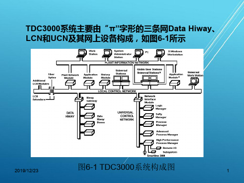
TDC3000系统主要由“π”字形的三条网Data Hiway、 LCN和UCN及其网上设备构成,如图6-1所示
2019/12/23
图6-1 TDC3000系统构成图
1
6.1.1 TDC3000系统的局部控制网络(LCN) 及设备
1、LCN网络及其连接
• LCN用以支持 TDC3000 LCN网络上设备或模件 (Module)之间的通信,遵循IEEE 802.4通信标准,采 用总线型通信网络,“令牌传送”协议。
图6-8 US外部设备的连接
8
4、历史模件
• 历史模件(HM)是TDC3000系统的唯一的永久性存储单 元,是LCN上唯一具有自启动能力的节点,也是LCN上的 必备节点。它用于存储系统文件、用户软件和过程历史数 据。HM的主要功能是用来存储系统软件、用户软件和过 程历史数据。
5、网络接口模件
• NIM的主要功能是:实现LCN与UCN的时钟同步;实现 LCN与UCN的实时数据交换,在LCN和UCN之间实现通 讯协议和数据格式的转换。
2019/12/23
2
Module #1
LCN I/F
Module #2
LCN I/F
Module #n
霍尼TDC3000系统讲义全解

DCS系统培训讲义郑栋2005年1月第一讲温米采油厂DCS应急预案温米采油厂DCS系统结构LCN(TPN)软件版本:R533.1GUS软件版本:GUS220.1指导思想:定期备份DCS系统软件、组态软件和用户软件,备份HM,在软件部分故障时可用备份软件进行恢复,或在HM硬件故障时,可临时采用备份盘引导、启动、监控,保障生产监控的安全性和连续性。
一、准备工作(一)LCN节点是否需要做工作每天检查LCN节点各设备运行状况是否正常。
无需其他工作。
(二)UCN节点做CHECKPOINT方法:在系统状态画面中选中NIM节点,选择下面NTWK/HWY STATUS命令,在UCN状态画面中,选中需要操作的APM节点,选择LOAD/SAVE RESTORE 命令,再选择 SAVE DATA命令,回车 Enter。
对每对 APM 都要进行此操作。
二、GUS系统的备份和恢复使用Ghost制作备份盘,或在D分区制作印象文件恢复更简单,快捷。
Gus系统主要备份流程图、恢复gus系统软件,配置节点、dde 等,这部分工作我操作的次数较多,能够熟练掌握。
三、制作紧急恢复盘并在故障时进行恢复(一)制作虚拟盘1、菜单栏— access — mount/dismount emulated disk2、如果菜单上面的两个输入框内已经安装了虚拟盘,选择Dismount button 卸载虚拟盘。
3、选择creat button开始创建一个新的虚拟盘4、输入新文件名:ed###.lcn,###代表分区号,我不明白文件名的命名规则,为什么不能随意命名?(肯定可以随意命名,只要不重名就行,只是后缀名必须是lcn。
)5、制定文件位于的目录,比如c:\backup6、选择open button7、设置虚拟盘参数 size=20mb,acllocation=reservedAccess=read/write, size可设置成多大,因为如果把所有的文件都备份到一张虚拟盘上,可能需要200—250mb(我认为需要制作两种虚拟盘,一种是FastLoad盘,需20M,另一种是备份盘,你们的系统100M就可以)。
TDC3000体系结构
第二章TDC3000体系结构1. 概述1975年11月Honeywell公司在世界范围内率先推出了以微处理器为基础的分散控制系统TDC2000(Total Distributed Control,TDC)系统。
经过十多年的发展,Honeywell公司的DCS经历了多次改进与完善,形成了一个庞大的产品系列。
其系统的发展过程大致如下。
1975年推出了TDC2000系统,在随后的几年里,对TDC2000数据高速通道(Data Hiway)设备功能进行了强化和完善,相继推出了多功能控制器(Multifunction Controller,MC)、批量控制器(Batch Controller)、增强型操作站(Extension Operator Station,EOPS)。
1984年以IEEE 802.4和ISO 8802/4通信标准为基础,开发了局部控制网络(Local Control Network, LCN),推出了TDC3000系统。
原有的TDC2000系统的设备通过数据高速通道接口(Hiway Gateway,HG)与LCN相连,成为TDC3000系统的基本组成部分。
1988年,推出通用控制网络(Universal Control Network,UCN),集数据采集和过程控制于一体的过程接口装置——过程管理器(Process Manager,PM)和逻辑管理器(Logic Manager,LM)。
UCN通过网络接口模件(Network Interface Module, NIM)与LCN相连,成为TDC3000系统的新的组成部分。
之后,又根据市场的需求,推出了适用于小规模过程控制管理的MICRO TDC3000系统。
1992年,推出了PM的改进产品先进过程管理器(Advanced Process Manager,APM)。
1994年,从开放性系统出发,推出了基于HP Unix操作系统的TDC3000X 系列。
荷尔士TDC3000到德尔塔V系统的控制转换服务数据表说明书
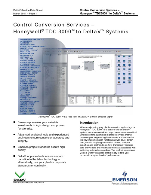
/DeltaVControl Conversion Services –Honeywell ® TDC 3000™ to DeltaV ™ SystemsHoneywell ®TDC 3000 ™ EB Files (left) to DeltaV™ Control Modules (right)⏹ Emerson preserves your valuableinvestments in logic design and proven functionality. ⏹ Advanced analytical tools and experiencedengineers ensure conversion accuracy and integrity. ⏹ Emerson project standards assure highquality. ⏹ DeltaV loop standards ensure smoothtransition to the latest technology –alternatively, use your plant or corporate standards for continuity.IntroductionWhen modernizing your plant automation system from aHoneywell ® TDC 3000™ to a state-of-the-art DeltaV™system, accurate control and logic conversions are critical. Emerson offers automated migration services that will preserve your engineering investments and ensure that the new implementation functions as well as, or better than, the old. Applying conversion utilities, platform expertise and controls know-how dramatically reduces data entry errors and minimizes the risks associated with switching automation suppliers. The controls conversion yields a DeltaV database that is ready to take yourprocess to a higher level of performance.BenefitsEmerson preserves your logic design and proven control system functionality. Emerson understands that the engineering investment in your current automation system represents a huge intellectual asset that has evolved over many years. Protecting the value of that asset is a top priority. Your new technology then becomes a platform for even higher levels of operational excellence.Automated analysis ensures accuracy. Emerson automated tools- Analyze your Honeywell EB files,- Identify recurring loop structures,- Map structures to DeltaV templates,- Generate an exception report of applications that are custom (non-recurring), and require manualreview and redesign and- Combine results in a work package for theengineering team.This analysis reduces manual effort, minimizes risk, and delivers intelligent information to accelerate the controls re-implementation process.Emerson project standards assure high quality. For all aspects of control project implementation, Emerson follows established global standards and best practices. Project teams include engineers experienced with Honeywell TDC 3000 systems and DeltaV experts. DeltaV loop standards ensure smooth transition. Loop standards establish guidelines for consistency in implementing control schemes, alarm management, reports and data for displays. By using DeltaV pre-configured module libraries, engineers establish a database that is relatively easy to maintain. This is the standard practice. As an option, Emerson engineers can incorporate your existing plant loop standards into the database, for continuity.Service DescriptionA typical controls conversion project includes the following steps:Capture Configuration. The customer completes a migration questionnaire, makes a backup of Honeywell TDC 3000 EB files and submits these to the Emerson services team.Analyze Inputs. Emerson engineers first assess I/O counts and types, TDC 3000 points, and application complexity. They verify that proposed DeltaV hardware and software meet the project requirements.Project Kick-off. Emerson personnel participate in a project kick-off meeting to review project scope, deliverables and schedules. Agree on Standards. The project team proposes configuration standards that will apply throughout the DeltaV implementation. These may include module naming conventions, use of DeltaV module libraries and specifications for modifying certain modules.Convert Loop Structures. Engineers automatically generate new DeltaV control modules by applying pre-defined library module templates for common TDC 3000 loop structures. They generate modules for complex TDC 3000 loop structures from detailed documentation and graphical loop representations. The resulting DeltaV modules database is then ready to download.Develop Configuration Solutions. E ngineers apply TDC 3000 and DeltaV systems expertise to convert user-defined code, ladder logic, batch controls and special purpose points to functional equivalents in the DeltaV system.Test. Engineers download the complete DeltaV database and perform a functional test of each module type using simulation.Optional ServicesSite Services. Emerson specialists can install the automation system, commission loops and bring your system online, to the full satisfaction of plant operations and management personnel.Custom Library Development. Emerson conversion utilities enable engineers to easily and efficiently create custom library modules that incorporate your plant control standards and strategies in the new DeltaV system.Operator Training. Emerson offers a comprehensive suite of training courses for operators, engineers and maintenance personnel. Traditional classroom, e-learning or custom onsite classes with hands-on practical learning exercises are available to satisfy all your training needs.Simulation Services. Simulation provides valuable feedback for verification of your database and logic configurations. Emerson engineers can help you thoroughly check the new DeltaV configuration.System CompatibilityDatabase conversion services for Honeywell TDC 3000 apply to the following devices and point types:Data Hiway LEPIU, LLPIU, HLPIU, DHP, and Basic / Extended / Multifunction Controllers. Also E / PLCG (DHP emulated) points.Universal Control Network PM, APM, HPM, LM. Application Module Most point types.Inputs are Honeywell TDC 3000 EB files. Outputs are DeltaV electronic configuration files compatible with DeltaV v9.3 or higher.To locate a sales office near you, visit our website at: /reach Or call us at:Asia Pacific: 65.777.8211Europe, Middle East: 41.41.768.6111 North America, Latin America: +1 800.833.8314 or +1 512.832.3774For large power, water, and wastewater applications contact Power and Water Solutions at: Or call us at:Asia Pacific: 65.777.8211Europe, Middle East, Africa: 48.22.630.2443 North America, Latin America: +1 412.963.4000© Emerson Process Management 2011. All rights reserved. For Emerson Process Management trademarks and service marks, go to: /home/news/resources/marks.pdf.Honeywell International Inc. claims to own the following mark: Honeywell TDC 3000. All other marks are the property of their respective owners.The contents of this publication are presented for informational purposes only, and while every effort has been made to ensure their accuracy, they are not to be construed as warrantees or guarantees, express or implied, regarding the products or services described herein or their use or applicability. All sales are governed by our terms and conditions, which are available on request. We reserve the right to modify or improve the design or specification of such products at any time without notice.Ordering InformationRelated ServicesThis service delivers a DeltaV control configuration.Emerson also offers efficient engineering services for the DeltaV operating environment.⏹ DeltaV Display Transition Services forHoneywell Systems. This service examinesexisting Honeywell displays to identify vital process representations. This information is then incorporated into new DeltaV display development.Related ProductsIn planning a Honeywell TDC 3000 to DeltaV system migration, you may also want to explore the following:⏹ DeltaV Connect ™ Solution for Honeywell ®Systems. This DeltaV human machine interface(HMI) connects to the Honeywell LCN. This solution includes hardware, software and services to convert operator interface points, alarms, and process displays.Prerequisites⏹ Request a services proposal from an EmersonProcess Management sales office.⏹ Complete a questionnaire, providing details about theTDC 3000 system and its applications. Capturecurrent TDC 3000 database backup files on CD / DVD or other PC-readable media. Submit the completed questionnaire and backup files to your Emerson sales office contact.⏹ Attend DeltaV configuration training.Related Links/Honeywell/ProcessAutomationServices /DeltaV。
- 1、下载文档前请自行甄别文档内容的完整性,平台不提供额外的编辑、内容补充、找答案等附加服务。
- 2、"仅部分预览"的文档,不可在线预览部分如存在完整性等问题,可反馈申请退款(可完整预览的文档不适用该条件!)。
- 3、如文档侵犯您的权益,请联系客服反馈,我们会尽快为您处理(人工客服工作时间:9:00-18:30)。
LLocal Control NetworkSpecification andTechnical DataLC03-500R5001/96LC03-500Page 2TDC 3000Specification and Local Control Network Technical DataIntroductionThis publication defines the significant functions of theTDC 3000 Local Control Network (LCN). The Local ControlNetwork is a local area network through which TDC 3000modules communicate with each other. Multiple LCNs can be linked together through Network Gateways, as shown in Figure 1.Two coaxial cables provide the primary medium that connects each module residing on a Local Control Network. Optional fiber optic communication links can be used to join LCN segments or to connect remote UniversalStations to the LCN. The Local Control Network carries all of the information that is transferredbetween the modules, including information going to or from the modules, and information going to or from process subsystems integrated into the TDC 3000System.For more information about the relationships of the TDC 3000modules and the types ofinformation carried on the Local Control Network, refer to the System Technical Datadocument. The Network Gateway Specification and Technical Data describes how two or more LCNs are interconnected.LC03-500Page 3FUNCTIONS•Carries all information transferred between the modules on the network.•Ensures the timely exchange of information through an efficient protocol and high-speed communication.•Provides highly secure communication through active and backup cables,and message-integritychecking.Functional DescriptionBecause the Local ControlNetwork provides rapid, secure communication between allmodules, distributed processing with centralized operations is a reality in TDC 3000 Systems. All modules are assured access to the network, even during a peak load. Because of thedeterministic token-passing algorithm employed,communication delays do not become excessive. Modules can be added to or removed from the network without disrupting ongoing operations.High-Speed CommunicationAll information is transferred serially at 5-million bits persecond. Information is transferred in frames of varying lengths.There are several types of frames,including frames that transfer commands, aid in diagnosis,transfer information, and control access to the network.Access to the NetworkA "token-passing" technique is used to control access to thenetwork. A token frame is passed among the modules to determine which one has access to the network. The Local Control Network is a broadcast type of local area network. All modules "hear" all transmissions, but they accept only information intended for them.Figure 2 is a simplified flow chart of the network-accessmechanism. When a module receives a token frame and has nothing to transmit, it passes the token to the next module with a higher address. For example,when module number 4 receives the token frame but has nothing to transmit, it passes the token frame to the next module,normally number 5. When the highest-numbered modulereceives the token frame but has nothing to transmit, it passes the token to the lowest-numbered module. Sixty-four modules can exist on a single (extended) LCN,assigned to addresses rangingfrom 1 through 127. System efficiency is improved by using contiguous addresses.A module "holding" the token has access to the network to transmit one frame. When a module receives the token and hassomething to transmit, it transmits one frame and then passes the token to the next module.The information frame transfers from 100 to 2000 bytes ofinformation from one module to another module. Thedestination-address field can specify the physical address of a module or it can specify a logical-node address (up to 8192addresses). When a logical-node address is specified, all modules that have the specified logicalLC03-500 Page 4node accept the information. In addition, an originating node can broadcast a message to all nodes. In these ways, information can be transferred throughout the network without regard for the physical location of sources and destinations.SecurityThe use of dual cables, CRC verification on every received frame, and message-length checks by software ensure an extremely secure network. Undetected errors are virtually nonexistent. Detected errors, which are also very rare, can be corrected by a repeat transmission by the application software.The frame-check sequence (FCS) that is near the end of every frame contains a 16-bit polynomial checksum that is a unique representation of all of the information contained in the frame. The checksum is regenerated as the frame is received in each module and the regenerated checksum is compared with the FCS field. If an error is detected, the frame will be retransmitted as the result of timeout for lack of response.The Local Control Network Interfaces in all modules have transmission and reception circuits for both coaxial cables. Should a cable, a transmitter circuit, or a receiver circuit fail, there is a backup to take over for it. The transmitter and receiver circuits (transceivers) are transformer-coupled to provide electrical isolation between the modules on the network. The transceivers are designed so that a circuit failure cannot affect the operation of the cables or other transceivers.All modules transmit all frames on both cables. They normally "listen" on the active cable. The active cable is determined by cooperative, network-management software in eachmodule.Network TimeSynchronizationAccompanying the otherinformation carried on the LocalControl Network is a system-clocksynchronization signal. There aretwo types of signals that can begenerated, depending on thetype of boards used in the LCNmodules. The recentlyintroduced high-density (K2LCN)boards are capable of generating,and receiving, digital clocksynchronization data frames thatare transmitted at the standard5 MHz rate. Modules that do notcontain the K2LCN boardsrequire a special 12.5 kHz clocksynchronization signal.These signals are used tosynchronize timekeeping in themodules. The date and time-of-day counters in the modules arestarted and maintained by a framecontaining the actual real time,which is sent out on the LCNevery 50 ms. The clocksynchronization signal on thenetwork synchronizes thecounters so that all time countschange at the same time.Clock-signal propagation tomodules connected by LCNExtender links occurs as part ofnormal message handling forK2LCN 5 MHz signals.Propagation over Extender linksis optional for 12.5 kHz signals;when implemented, separatefiber optic fibers are used.One of the modules on thenetwork is the source of themaster clock-synchronizationsignal, with a second moduleproviding a backup "slave" clock.If there is a mixture of moduleswith and without K2LCN boards,two of the non-K2LCN modulesserve as 12.5 kHz master andslave. A K2LCN module thensynchronizes its clock with themaster and transmits digital clock5 MHz message frames to theother K2LCN modules on theLCN. Hiway Gateways or NetworkInterface Modules typically areselected as clock sources, butany modules can be selected bythe system engineer at the timeof network configuration.OptionsThe Local Control Networkoptions are the number and typeof modules on the network, thelength and mix of cables, the LCNExtender (LCNE) and the LocalControl Network Fiber Link(LCNFL).The maximum number ofmodules on a single LCN is 64when an LCNE is included, or 40modules without an LCNE.Where a module has a backup,the module and its backup countas two in the total count ofmodules on the LCN.Multiple LCNs are interconnectedusing a Network Gateway througha Plant Information Network (PIN).For more information, refer to theNetwork Gateway Specificationand Technical Data.Each coaxial-cable segment canbe up to 300 m (1000 ft) long,and each fiber opticcommunication-link can be up to2000 m (6500 ft) long. Figure 3shows an example of an LCN withmultiple coaxial and fiber opticcable segments. There can beup to six fiber optic links, and thecombinations of coaxial and fibersegments are limited by theconstraint that the signal pathbetween any two modules on anLCN cannot include more thantwo fiber optic communication-links.The LCNE retransmits signalsbetween coaxial and fibersegments.The LCNFL allows connection ofa single remote module (generallya Universal Station) to fiber cableswithout the need to create acoaxial cable segment.LC03-500Page 5*TDC 3000 LCN cables have beendesigned and tested by Honeywell IAC to meet strict standards of performance. Other "RG-59-like"or "RG-11-like" cables have not been tested and qualified for use in the system; therefore, no substitutions are approved by Honeywell.Physical DescriptionThe primary Local ControlNetwork hardware consists of the coaxial cables,* tee connectors,termination connectors, and a Local Control Network Interface board in each module. Figure 4shows how the coaxial cables are connected to each module.The optional fiber optic hardware consists of the fiber optic cables (provided by others) and twoboard types, the LCNE board and the LCNFL board.The LCNE board mounts in any spare paddleboard slot in any module without affecting itsoperation, except to draw power.As shown in Figure 5, a single LCNE connects one coaxial cable (active or backup) to two fiber optic cables (transmit andreceive). To protect against loss of communication in the event of a single-node failure, it is recommended that only one LCNE board be connected to a module.As shown in Figure 6, an LCNFL board replaces the coaxial cable transceiver-board in a remote module, and connects to the four fiber optic cables required for extension of a redundant LCN.LC03-500 Page 6LC03-500Page 7LC03-500Page 8Local Control Network SpecificationsPhysical CharacteristicsType of Cable/Connections (LCN Cables A & B)*Coaxial cables within cabinets (75 ohm)Honeywell Part No. 51190837-100RF coaxial BNC-type connector for above Honeywell Part No. 30732054-001BNC T-Connector at module Honeywell Part No. 51190728-10575 ohm terminator for each end of LCN Honeywell Model No. C-KCA02Coaxial cables between cabinets and modules Honeywell Part No. 51190838-100RF coaxial BNC-type connector for above Honeywell Part No. 30732050-001Fiber optic cable can be used between coaxial cable-bus segments to provide extended bus runs.Inquire at factory for recommendations.Maximum Length300 meters (1000') for coaxial cable-bus segment.2 kilometers (6562') for fiber optic-cable run.Maximum Number of TDC 300064 modules total for entire network, where a network consists of Modules per LCN coax segments plus fiber optic extenders.Maximum Number of Electrical40Loads (modules or extenders)per LCN SegmentFiber Optic Extension Up to two fiber optic segments between any two modules.Up to six fiber optic extensions connected to any coax segment. Operating CharacteristicsData Transfer Speed 5 million bits per secondDat Encoding/Transfer Method Manchester data encoding with token-passing access protocol. Real-Time Clock Signal Transferred over coaxial cable at 12.5 kHz. Clock signalpropagation between LCN extensions is optional (requiresseparate fiber optic fibers).* TDC 3000 LCN cables have been designed and tested by Honeywell to meet strict standards of performance. Other "RG-59-like" cables have not been tested and qualified for use in the system; therefore, no substitutions are approved by Honeywell.While this information is presented in good faith and believed to be accurate, Honeywell disclaims the implied warranties of merchantability and fitness for a particular purpose and makes no express warranties except as may be stated in its written agreement with and for its customer.In no event is Honeywell liable to anyone for any indirect, special or consequential damages. The information and specifications in this document are subject to change without notice.Printed in U.S.A. — © Copyright 1992 - Honeywell Inc.。
