霍尼韦尔 FCU样本
霍尼韦尔空气净化电子样本
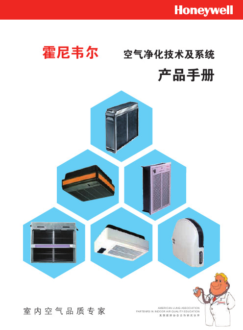
600×442×162mm
16.4kg(运输) 14kg(安装)
UL 认证
F58G 空调箱适配型电子空气净化机
特性:
• 每个单元最大处理容量2000cfm(3400m3/h) • 多个单元可组成排列的空气净化机 • 指示灯可显示正常运行及故障情形 • 可与楼宇管理系统连接使用 • 电镀的机箱可防止生锈 • 测试按钮检查系统运行 • 预过滤网保护电子单元不受大颗粒污染 • 可有效去除悬浮在空气中直径为0.3μ的微粒 • 可与紫外线灯配套应用 • 发生误操作或电子单元需要清洗时,电子继电器将停止工作 • 电子单元在相当范围内负载时,固态电源供应组合可自我调
性能参数表
型号 电子单元数量 处理风量 安装方式 面板 / 格栅形式
组成
电源 运行环境 尺寸 重量 认证
F52G1012
F52G2002
1
1000cfm (1700m3/h)
回风口型
百叶
固态电源供应组合, 电子单元,预过滤网,格栅
电子单元,预过滤网,格栅
220V/50Hz
无电源供应
40oF-125oF (4oC-52oC)
740×485×273mm
31.5kg(运输) 29.5kg(安装)
18.5kg(运输) 16kg(安装)
UL 认证
CE 认证
F57A/B 嵌入式电子空气净化机
特性:
• 三速电机驱动循环风机 F57A额定处理风量可达875cfm (1500m3/h) F57B额定处理风量可达460cfm (782m3/h)
做为整体过敏症治疗方案中的一部分,Honeywell电子空气净化机的应用可以减轻过敏症和其它呼吸问题给患 者带来的伤害。然而,并不是所有类型的空气净化机都能达到此处理效果。
Honeywell_传感器_技术参数 2
目录:水系统传感器 (2)水流开关WFS-1001-H (2)液位开关MAC-3-5M (2)水管式压差传感器P7620C (3)水管式压力传感器P7620A (4)流量变送器8550+2517 (5)VF20T浸入式温度传感器 (5)风系统传感器 (7)DPS系列气流压差开关 (7)DPTM系列压差变送器 (7)风管式温度传感器LF20 (8)风管式温度传感器LF20-C (9)室外温度传感器T7416A1022 (9)室内温度传感器T7412A1000 (9)室内温度传感器CTR21 (10)风管式温湿度传感器H7050B1018 (10)风管式温湿度变送器H7050B1117 (11)室内温湿度变送器H7030A1000 (12)室内温湿度传感变送器H7012B1023 (12)室内温湿度传感器CTR21-H (13)风管式温湿度传感器H7015B1020 (14)室外温湿度传感变送器H7508A1042 (14)CDS2000 系列二氧化碳传感器 (15)C7110C1001(替换已停产的AQS51) 系列二氧化碳传感器 (15)AQS71-KAM(替换已停产的AQS51-KAM) 系列二氧化碳传感器 (16)GD250W3E 系列一氧化碳传感器 (17)C7110A1005系列房间空气质量传感器 (17)L4064K1006B 高温断路开关,手动复位 (18)T6950A1000 低温短路开关,手动复位 (18)数字化挂墙模块T7560 温度传感器 (19)数字化挂墙模块T7460 温度传感器 (19)水系统传感器水流开关 WFS-1001-H应用∙ WFS 水流开关具有SPDT 输出,性能优异,高精度可靠性,可安装在水管和对铜无腐蚀性液体中,当液体流量达到整定速率时,可不到整定点,其一个回路关闭,另一个回路打开,典型应用于连锁作用或断流保护的场所。
∙ WFS 系列开关仅用0℃以上液体介质,它亦可于高盐或氯气的液体,但是非易燃介质。
HoneywellDCS资料

硬件垂直设计,有效利用空间
集成接线,减少 占用面积 ;
双列接线端子, 易于安装和维护;
可选冗余,最大 增加系统的可用 性;
C300 控制器水平与垂直安装比较:最容易维护
Experion C300
• 双端子I/O接线, 实现接线密度与 易于安装的平衡
• 可插拔的端子, 和双端子接线易 于接线与维护
冗余 I/O
Local Control Network
无线变送器
HPM
BC Controller
TPS/TDC投资保护 Experion on LCN
SIL 3 安全系统 Safety Manager
C系列控制器
New
C200
Fault Tolerant Ethernet
Control Firewall
其它系统
• 四端子接线对于底 端的接线造成困难
• 并列紧挨的模块容 易造成接线混淆
: C300 控制器水平与垂直接线比较
Experion C300
其它系统
无背板 易于散热
多点进线 垂直接线
易于维护,安装 …和 省钱
需要更多模件
接线分层难以触 及底层 接线混在一起
现场接线与系统接 线混在一起,容易 造成干扰 单点进线
C300 控制器和C系列 I/O 概貌
AGENDA
简介 机柜及电源 控制器 I/O模块 现场总线 控制防火墙
AGENDA
简介 机柜及电源 控制器 I/O模块 现场总线 控制防火墙
无线访问
防火墙
Experion PKS 架构
现场ห้องสมุดไป่ตู้动操作站
Mobile PKS
霍尼韦尔氢气纯度仪说明书模板
目录1.前言………………………………………………………………………………2 1.1概述……………………………………………………………….........2 1.2传感单元 (2)1.37866数字控制器 (3)1.4操作原理 (4)2.技术参数和选型 (6)2.1技术参数……………………………………………………………………62.2选型 (8)3.安装……………………………………………………………………….........9 3.1传感单元要求条件和定位 (9)3.2安装传感单元 (9)3.3管路连接 (9)3.4传感单元与数字控制器接线 (10)4.设置模式………………………………………………………………………11 4.1概述………………………………………………………………………11 4.2结构概述……………………………………………………………………...11 4.3单元设置组群 (11)4.4报警设置组群 (12)4.5M o d B U S通讯设置组群 (12)4.6校准组群………………………………………………………………………13 4.7状态组群………………………………………………………………………13 5.校准……………………………………………………………………………14 5.1概述……………………………………………………………………...14 5.2传感单元校准 (14)5.37866分析仪输入校准 (14)5.4模拟输出校准 (15)5.7安全锁定……………………………………………………………………...16 5.8设置报警极限 (17)6.操作………………………………………………………………………………18 6.1启动………………………………………………………………………18 7.排除故障…………………………………………………………………………19 7.1概述……………………………………………………………………...19 7.27866数字控制器检测 (20)附录 (21)1.前言1.1 概述美国HONEYWELL公司7866氢气纯度分析仪由三个基本部件组成: 传感单元( 变送器) , 控制单元( 接收器) ( 图1-1) 和电源。
霍尼韦尔在线式压力变送器资料

ST3000/900 系列全智能在线式压力变送器概述ST3000系列在线式压力变送器是以微处理器为基础的智能变送器。
最新推出的R300版本,全面提升了变送器的准确度、可靠性及长期稳定性指标。
它能测量各种液体和气体的压力并输出与被测量相对应的4~20mA模拟信号和数字信号。
它独特的温度误差自动修正功能使得本产品能满足苛刻的使用环境。
它具有DE通讯协议,可与霍尼韦尔的ExperionPKS TM集散控制系统和智能现场通讯器(SFC)实现双向数字通讯,消除了模拟信号传输误差,方便了变送器的调试、校验和故障诊断。
特点1.先进的传感器技术:采用离子注入硅技术,在差压传感器上集成了温度传感器,随时修正过程温度引起的误差,提高了测量精度和稳定性。
2.高可靠性:平均无故障时间470年。
3.高稳定性:±0.015%/年。
4.高精度:±0.065%。
5测量范围宽:STG94L0~3.5MPaSTG97L0~21MPaSTG98L0~41.5MPaSTG99L0~69MPa6.规格齐全:接液部分有各种防腐材料备选,能满足各种工况条件下的使用,特殊需求,请与霍尼韦尔公司现场仪表部联系。
7.具备各种本安和隔爆认证。
8.可选HART协议。
9.可选现场总线(FF)通讯协议。
10.使用现场通讯器或MCT多协议通讯器实现对ST3000变送器的组态、校验和故障诊断等。
11.可通过便携电脑,用SCT组态工具组态。
12.可与霍尼韦尔公司集散控制系统PKS实现数字一体化。
13.体积小,重量轻:1.7Kg。
测量对象1.压力测量应用场合1.电力2.钢铁3.石油、石化4.化工5.造船6.水泥7.水处理8.制药9.造纸10.食品及烟草:运行环境参数参考环境额定环境操作极限运输和存储环境温度(℃)25±1-40~70-40~85-55~125表体温度(℃)25±1-40~110-40~125-55~125湿度(%RH)10~550~1000~1000~100过压能力(MPa)STG94L STG97L STG98L STG99L 3.5 21 41.5 69真空度(kPaA)大气 3.30.3*电源电压,电流,和负载电压范围:10.8~42.4VDC电流范围:3.0~21.8mA负载:0~1440欧姆(见图4-1)*70℃时,2小时物理特性和认证机构隔离膜片材料316L SS,哈氏合金C-276过程接口材料316SS安装支架碳钢(镀锌)或不锈钢角支架,或碳钢平板支架填充液硅油DC200或CTFE(氟油)表壳环氧聚酯油漆,低铜铝合金。
霍尼韦尔楼宇自控系统介绍-控制器端

Excel 100C
Excel 10系列房间控制
SLIDE NO. 3
Excel 5000 控制器接口
自 由 编 程 控 制 器 Excel Web
型号
XL1000A500 / XL1000A1000
Excel Smart 500 XCL5010
Excel 500
XC5010C
Smart I/O Compact I/O
Controller Training 2006
SLIDE NO. 9
分布式 IO模块
型号
外观
XSL511
XFL521B
XFL522B
XFL523B
XFL524B
XSL513 XSL514
Controller Training 2006
描述 Lon 连接器
容量
特点
1、78Kbps Lon-Bus 通讯; 最多10个 2、快速连接滑动接头; I/O模块 3、24 VAC 提供所有模块供电
SLIDE NO. 10
分布式IO模块(DIO)的配置原则
1、每个XFL521B或 XFL522B或XFL523B 模块配置一个XSL513 底座。每个XFL524配 置一个XSL514底座
2、若干个DIO模块( 最多10个)配置一个 XSL511LON总线连接 器。
3、每组模块可安装在 XSL511 不同的自控箱内。自 控箱分别安装在不同 位置的机房内。
C o n n e c to r M o d u le X S L 511
0% AUT O
100%
1
2
3
4
5
6
7
8
1 0 A
1
1 0 A
Honeywell气体公共设备 HON 370 解剖分析说明书
2u r f Gas Pressure Regulator HON 370Dr a f t Applications, characteristics, technical data applications• D irect-acting gas pressure regulator for commercial and industrial applications and local supply stations.• E specially suitable for dynamic regulating lines (e.g. gas furnaces, burner switching, gas engine operation)• Can also be used as a component for gas consumption devices according to EC Directive (90/396/EEC)• A s a gas pressure regulating device with electrical consequential value (motorised actuator) and pneumatic consequential setpoint • S uitable for gases in accordance with DVGW Worksheet G 260 and neutral, non-aggressive gases; other gases on requestcharacteristics• Version with integral overpressure protection (IS) • Fail open (FO) error type • G as pressure regulator with incorporated axial safety shut-off valve (SSV) – optional designs with safety relief valve (SRV) for the relief of leakage gases or with safety diaphragm • Large inlet pressure range• Optional installation of different valve seat diameters is possible• Easy to maintain, thanks to interchangeable functional units (plug-in modules)• SSV optionally available in function class A or B• Pressure equalisation valve (internal bypass) integrated in the SSV actuatorVersions (options)• Without SSV• SSV with manual release• Electromagnetic remote release with SSV • W ith electric SSV ‘CLOSED’ position indicator by means of inductive proximity initiator or reed sensors and intrinsically safe current circuit• Regulating device with leak gas SRV (p d up to 0.8 bar) or safety diaphragm (p d up to 1.0 bar)• With vent valve HON 915 (SSV/RA) or tripping valve HON 919 (SSV)• With noise reduction3f Gas Pressure Regulator HON 370Applications, characteristics, technical data4f Gas Pressure Regulator HON 370f tn**) T he limitation of the maximum inlet pressure range ∆ p u max does not occur due to strength reasons; it is intended to maintain the accuracy class AC.***) For outlet pressures p d > 200 mbar, otherwise p u max = 10 barbetween the setpoints of (p dso and p dsu) must exceed the sum of the values set for ∆p wo and ∆p wu by at least 10 %.(p dso – p dsu)min = 1.1 ∙ (Δp wo + Δp wu)**) We recommend a maximum re-engage differential of < 4.5 bar to facilitate engaging the control device.Applications, characteristics, technical data5En t w u r f Gas Pressure Regulator HON 370Construction and mode of operationconstruction and mode of operationThe purpose of the direct-acting gas pressure regulator HON 370 is to substantially stabilise the outlet pressure independently of any inlet and outlet pressure changes in the regulating line. The device consists of a regulating assembly (1), final control element (2), SSV final control element (3) with tripping device (4) and control device (5) and the main valve body (6). The required setpoint is adjusted via the setpoint adjuster (14).The control element of the regulating assembly is equipped with a pressure-compensating diaphragm (7). The regulating assemblies RA 1, RA 2 and RA 3 may be optionally equipped with a safety relief valve (9). The outlet pressure you want to control is fed to the measuring diaphragm unit via the measuring line connection. The measuring unit compares the actual value to the setpoint defined by the force of the setpoint spring (10). If a deviation is detected, the valve stem (11) will adjust the control element (2) in order to match the actual value to the setpoint again. At zero drop, the device will seal bubble-tight.The version with a safety diaphragm RE 1, RE 2 and RE 3) has an extra diaphragm (52) across the measuring diaphragm (8) which will seal the upper part of the diaphragm body in case the diaphragm (8) breaks so that the gas cannot escape into the atmosphere.A metal foam cylinder (12) may be inserted into the control element to reduce noise.If the outlet pressure exceeds or falls below the predefined limit values, the upstream safety shut-off valve will stop the gas flow. To accomplish that, the measuring diaphragm (20) of the control device (5) is shifted according to the comparison of set and actual values in such a way that the balls (21) of the release mechanism release the switch stem (22). Through the spring force of the spring (24), the switch stem will flip against the bush of the tripping device (4), thus unblocking the axle (23) of the SSV control element (3) so that the SSV closes. Now the SSV may be opened only by hand. For this, the outlet pressure at the measuring point must be reduced below the overpressure release / increased above the underpressure release by a value that must correspond at least to the re-engage differential (∆p).assembly, commissioning and maintenanceFor assembly and maintenance, please refer to DVGW Worksheets G 491, G 495 and G 600, and the manual.The “Operating and maintenance instructions ; spare parts” contain detailed information on installation, start-up, maintenance and the most important spare and replacement parts.The gas pressure regulator should preferably be installed in the pipework in a horizontal position.6u r f 8973232421225Gas Pressure Regulator HON 370Dr a f t Construction and mode of operation Safety diaphragm (52)Version with safety diaphragmVersion without safety diaphragm,with safety relief valve for the relief of leakage gasesVent bore14101Vent line connection(optionally withHON 915)*Measuring line connection1121264Measuring line connection20Optionally with vent valveHON 915(optionally with HON 919)*) attention! Not for SRV leak gas7f Gas Pressure Regulator HON 370Dimensions, weight, flange version**) Connection element: DN 25: Screws M12 x L EN 24014 - 5.6 DN 50 to 100: Screws M16 x L EN 24014 - 5.6DN 150: Screws M20 x L EN 24014 - 5.6L varies depending on version8f Gas Pressure regulator Hon 370f t Connection9En t w u r f Hon 370 – 50 – k1a / E1 / Ha / f1 – 50 / 2S / 3 – Sonominal widthDN 2525DN 5050DN 8080DN 100100DN 150150control deviceSetting range (bar)W dsoW dsuK1a0.025 to 1.50.01 to 0.30K1a K2a1.5 to 7.00.06 to 1.0K2aElectromagnetic remote release Triggering at:current supply / current failureE1 / E2manual release Manual releaseHAremote indicationElectrical remote indication of the valve position “CLOSE” proximity initiator / reed sensorF1 / F2regulating assemblyDNValue Valve SRV blockedWith SRVWith safety diaphragmValve seat ø25RA 0250----250 –31----310 –RA 12511L1S251 –3111L1S311 –RA 22522L 2S 252 –3122L2S31 2 –50RA 025----250 –310----310 –500----500 –RA 12511L 1S 25 1 –3111L 1S 31 1 –5011L 1S 50 1 –RA 22522L 2S 25 2 –3122L 2S 31 2 –5022L 2S 50 2 –80RA 0600----600 –800----800 –RA 26022L 2S 60 2 –8022L 2S 80 2 –RA 36033L 3S 60 3 –8033L 3S 80 3 –100RA 0600----600 –800----800 –1000----1000 –RA 26022L 2S 60 2 –8022L 2S 80 2 –10022L 2S 100 2 –RA 36033L 3S 60 3 –8033L 3S 80 3 –10033L 3S 100 3 –150RA 310033L 3S 100 3 –14033L3S1403 –Specific outlet pressure rangeW dsSetpoint spring no.Setpoint spring no.RA 0RA 1RA 2RA 320 mbar to 30 mbar 25 mbar to 50 mbar 45 mbar to 75 mbar 70 mbar to 100 mbar 90 mbar to 160 mbar 150 mbar to 200 mbar*190 mbar to 260 mbar 250 mbar to 300 mbar 290 mbar to 360 mbar 350 mbar to 400 mbar 390 mbar to 500 mbar 490 mbar to 560 mbar 550 mbar to 660 mbar 650 mbar to 760 mbar 750 mbar to 800 mbar 790 mbar to 900 mbar 890 mbar to 1 bar1,000 mbar to 2,000 mbar 1,500 mbar to 3,000 mbar 2,500 mbar to 3,500 mbar 3,000 mbar to 4,500 mbar 4,000 mbar to 5,000 mbar1233+43+51234567891011121314151617123456789101112131415161712345612345678910111213141516171233+43+5Device designation ExampleT y p eN o m i n a lw i d t h D NS S V c o n t r o l d e v i c eE l e c t r o m a g n e t i c r e l e a s eM a n u a l r e l e a s eE l e c t r i c a l r e m o t e i n d i c a t i o n o f t h e “C l o s e d ” p o s i t i o nV a l v e s e a t d i a m e t e rR e g u l a t i n g a s s e m b l y d e s i g nR e g u l a t i n g a s s e m b l y s e t p o i n t s p r i n g n o .S p e c i a l d e s i g n (m u s t b e e x p l a i n e d i n m o r e d e t a i l )*) RA 3: 150 mbar to 250 mbar Subject to technical changesGas Pressure Regulator HON 370r fD r a f t 10u11E n t w u r f Gas Pressure Regulator HON 370HON 370.002017-01© 2017 Honeywell International Inc.For More InformationTo learn more about Honeywell’s Advanced Gas Solutions, visit or contact your Honeywell account manager GERMANYHoneywell Process Solutions Honeywell Gas Technologies GmbH Osterholzstrasse 4534123 Kassel, GermanyPhone: +49 (0) 561 5007-0Fax: +49 (0) 561 5007-107。
霍尼韦尔传感与控制部产品手册

传感与控制应用解决方案
产品手册
霍尼韦尔传感与控制部,一直以来都 是行业内的创新先锋。
霍尼韦尔传感与控制部提供超过 5 万种的产品,包括快动、 限位、轻触和压力开关,以及位置、速度、压力、温湿度、 电流和气流传感器,是传感与开关产品涵盖范围最广的厂 商之一。
霍尼韦尔传感器、开关和控制部件严格按照技术规范设计 制造,性能更好,效率更高,安全性更强。产品的每一部 分都具有增强的精度和耐用性,因而使整个产品的输出结 果和耐用程度也得到了提高。对我们客户来说,这可降低 费用支出和运营成本。我们遍及全球的业务足迹和渠道系 统可使这些产品的定价更具竞争力,以适应您所选择的应 用领域的需要,同时我们还能提供第一时间的技术支持。
也可用于极限检测接近程度检测提供一系列各种不同的标准产品同时也有客户定制化解决方案来满足特定的客户需要在机械方面和光学方面与霍尼韦尔的光电二极管光敏晶体管光敏达林顿检测器和光敏施密特触发器相匹配金属和陶瓷封装可用在高脉冲电流应用中以获得更大感应距离同时器件的总功率耗散又比较低gaaias发射器在同样正向电流下一般要比gaas发射器的功率输出大70这样可以延长led使用寿命同时对用电量敏感的电池应用或便携式应用来说又可减少电流消耗一级封装检测器产品概述编码检测器是一个单片集成电路它由两个相邻的二极管放大器和施密特触发器输出级组成
Limiห้องสมุดไป่ตู้lessTM 无线产品解决方案
LimitlessTM 无线限位开关. . . . . . . . . . . . . . . . . . . . . . . . . . . . . . . . . . . . . . 39 无线监视器与接收器 . . . . . . . . . . . . . . . . . . . . . . . . . . . . . . . . . . . . . . . . . 40
霍尼韦尔 S10010 S20010 A使用说明书

® U.S. Registered TrademarkEN0B-0463GE51 R0418Copyright © 2018 Honeywell Inc. • All rights reservedS10010 / S20010SPRING RETURN DIRECT-COUPLED DAMPER ACTUATORS10/20 Nm (88/177 lb-in) FOR MODULATING AND FLOATING CONTROLPRODUCT DATAGENERALThese direct-coupled damper actuators provide modulating / floating control for: ∙ air dampers, ∙ VAV units, ∙ air handlers, ∙ ventilation flaps, ∙ louvers, and∙ reliable control for air damper applications with up to1.5 m 2 / 16 sq.ft (10 Nm / 88 lb-in) or 4.6 m 2 / 50 sq.ft. (20 Nm / 177 lb-in) (seal-less dampers; air friction-dependent).FEATURES∙ Self-centering shaft adapter ∙ Removable access cover∙ Mechanical end limits (non-adjustable)∙Rotation direction selectable by choice of mounting orientation∙ Mountable in any orientation (IP54 only whenmounted on a horizontal shaft with access cover below the shaft)∙ Mechanical position indicatorSPECIFICATIONSSupply voltage S10010 / S20010 24 VAC ±20% / 24 VDC, 50/60 Hz Nominal voltage S10010 / S20010 24 VAC / 24 VDC, 50/60 Hz All values stated hereinafter apply to operation under nominal voltage conditions. Power consumption Holding Driving S10010 5 VA / 5 W 14 VA S20010 5 VA / 5 W 16 VA Ambient limitsAmbient operating limits -40...+60 ︒C Ambient storage limits -40...+70 ︒C Relative humidity 5...95%, non-condensing SafetyProtection standard IP54 Overvoltage category III Lifetime Full strokes 60000 Repositions 1.5 million Full stroke spring return 60000 MountingRound damper shaft 10...27 mm Square damper shaft 13...19 mm Shaft length 25 mm End switch (when included) Rating 5 A (resistive) / 3 A (induct.) Triggering points 7︒ / 85︒ Torque rating S10010 10 Nm (88 lb-in) S20010 20 Nm (177 lb-in) Runtime 90 sec (50 Hz) Spring return timing 20 sec (50 Hz) Rotation stroke 95︒ ± 3︒ Dimensions see Fig. 8 on page 6 Weight 3.2 kg Noise rating Driving 40 dB(A) Holding 20 dB(A) (no audible noise) Spring return 50 dB(A)SmartAct S10010, S20010 – PRODUCT DATAEN0B-0463GE51 R0418 2MODELSorder numbersupply voltage end switchespower consumption torque S1001024 VAC / 24 VDC-- 14 VA (driving) / 5 VA (holding) 10 Nm (88 lb-in) S10010-SW2 2 S20010-- 16 VA (driving) / 5 VA (holding)20 Nm (177 lb-in)S20010-SW2 2Product Identification SystemFig. 1. Product Identification SystemOPERATION / FUNCTIONSContents of Package1 Self-centering shaft adapter2 Retainer clip3 Rotational angle scales (0...90° / 90...0°)4 Mechanical end limits (non-adjustable)5 Hex wrench for manual adjustment6 Rotation direction switch7 Access coverRotary MovementThe actuators are designed to open a damper by driving the damper shaft in either a clockwise or counterclockwise direction.NOTE: Actuators are shipped in the fully-closed (springreturn) position.Position IndicationAn arrow molded into the hub points to tick marks on the label to indicate the hub rotary position.CCW to close (failsafe position)CW to open90°0°45°CW to close (failsafe position)CCW to open90°0°45°Fig. 2. Mounting orientationSmartAct S10010, S20010 – PRODUCT DATA3 EN0B-0463GE51 R0418Manual Adjustment IMPORTANTTo prevent equipment damage, before manual adjustment, you must remove power.The actuator can be operated with no power present. Use this feature during installation or to move and lock the damper or valve shaft position when there is no power.Operating the Manual PositioningTo operate the manual positioning with no power, proceed as follows:1. If the power is ON, turn it OFF.2. Insert the supplied hex wrench (key) as shown in Fig.3. 3. Rotate the key in the direction indicated on the cover.4. Once the desired position has been reached, hold the keyto prevent the spring return from moving the actuator. 5. With the key held in place, use a screwdriver to turn thegear train lock pin in the indicated direction until the detent is reached.NOTE: At the detent, the pin resists further rotation.6. Remove the key without rotating it further.Releasing the Manual PositioningTo release the manual positioning with no power present, proceed as follows:1. Insert the supplied key.2. Turn the key ¼ of a turn in the direction indicated on thecover.3. Remove the key without engaging the gear train lock pin.4. The spring will return the actuator to the failsafe position.NOTE: Once power is restored, the actuator will return tonormal automated control.Fig. 3. Manual positioningInternal End SwitchesNOTE: Only those actuators for which "-SW2" has beenspecified when ordering (e.g.: "S10010-SW2") feature internal end switches.The internal end switches are set to switch from "common" to "normally open" at angles of 7° (±3°) and 85° (±3°), respectively, from the totally counterclockwise position.Fig. 4. Internal end switch triggering pointsMechanical Stroke Limit ReductionFor applications requiring a span of less than 95°, a simple adjustment can be made. When the rotational mounting of the shaft coupling is changed, the actuator drives less than the full 95° stroke.The stroke is adjustable in 5° increments. Once adjusted, the actuator drives until the shaft coupling reaches themechanical stop (part of the housing). The stop causes the motor to discontinue driving, and the shaft coupling drives no farther. When the actuator returns, it stops at the fail-safe position.To set the fail-safe position, proceed as follows:1. Remove the retainer clip from the shaft coupling and set itaside for later use.2. Remove the shaft coupling from the actuator.3. Rotate the coupling to the desired fail-safe position,aligning it based on the stroke labeling. See Fig. 5.EXAMPLE: Setting the shaft coupling to an approx. fail-safeposition of 35° (as indicated on the housing) limits the stroke to 60° (see Fig. 5).4. Install the shaft coupling at this position.5. Replace the retainer clip on the shaft coupling using thegroove of the coupling.6. If necessary, replace the holder and position indicator onthe shaft coupling.SmartAct S10010, S20010 – PRODUCT DATAEN0B-0463GE51 R0418 4Fig. 5. Stroke reductionINSTALLATIONThese actuators are designed for single-point mounting.IMPORTANTTo prevent equipment damage, before manual operation, you must remove power.Mounting InstructionsAll information and steps are included in the Installation Instructions supplied with the actuator.Mounting PositionThe actuators can be mounted in any position (IP54 only when mounted on a horizontal shaft with access cover below the shaft). Choose a mounting position permitting easyaccess to the actuator's cables and controls. When stationing outdoors, equip with suitable cover to protect against UV and rain.Mounting Bracket and ScrewsIf the actuator is to be mounted directly on a damper shaft, use the mounting bracket included in the delivery package.Self-Centering Shaft AdapterThe self-centering shaft adapter can be used for shafts having various diameters and shapes (round: 10...27 mm; square: 13...19 mm).In the case of short shafts, the shaft adapter may be reversed and mounted on the duct side.StrokeThe stroke amounts to 95° ( 3°) and is mechanically limited by end limits (non-adjustable).WiringConnecting to the Power SupplyIn order to comply with protection class II, the power source of 24 V actuators must be reliably separated from the network power supply circuits as per DIN VDE 0106, part 101.Access CoverTo facilitate wiring the actuator to the controller, the access cover can be detached from the actuator.IMPORTANTRemove power before detaching the access cover. Once the access cover has been removed, please take care to avoid damaging any of the parts now accessible.Fig. 6. Access cover (S10010-SW2)Fig. 7. S10010-SW2 with access cover removedSmartAct S10010, S20010 – PRODUCT DATA5 EN0B-0463GE51 R0418Wiring DiagramsS10010 / S20010S10010-SW2 / S20010-SW2NOTE: Internal end switches S1 and S4 must be connected to the same power source.SmartAct S10010, S20010 – PRODUCT DATAManufactured for and on behalf of the Environmental & Energy Solutions Division of Honeywell Technologies Sàrl, Rolle, Z.A. La Pièce 16, Switzerland by its Authorized Representative:Home and Building Technologies Honeywell GmbH Böblinger Strasse 1771101 Schönaich, Germany Phone +49 (0) 7031 637 01 Fax +49 (0) 7031 637 740 EN0B-0463GE51 R0418Subject to change without noticeDIMENSIONS40M I N . 64247MIN. 76MIN. 76757ANTI-ROTATION BRACKET230 mm2 mm20 mm13 mm7 mm10 mmSHAFT ADAPTERALTERNATE POSITION1005050MIN. 15MIN. 155SHAFT ADAPTER SUITABLE FOR SHAFTS WITH LENGTH OF 25 ... 80 mmWHEN THE SHAFT ADAPTER IS INSTALLED IN ALTERNATE POSITION, THE POSITION INDICATOR IS NOT VISIBLE.170 (190)20...25 NmFig. 8. Dimensions (in mm)。
霍尼韦尔商业开关与传感器说明书
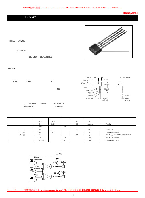
14Honeywell/Commercial Switch&Sensor 霍尼韦尔商业开关与传感器特点侧接收塑料封装TTL/LSTTL/CMOS 兼容反向逻辑输出线性或旋转编码器应用分辨率为0.229mm具有灵敏度温度补偿机械结构上和光谱上与SEP8506和SEP8706LED 相匹配HLC2701专为感测机械运动的速度和方向而设计。
应用包括旋转编码器或线位移编码器。
特别适用于光学鼠标中的编码器。
探测器为单片集成电路包括两个非常靠近的光电二极管、放大器和施密特触发器输出单元。
输出为NPN 集电极带10K Ω上拉电阻,可直接驱动TTL 负载。
探测器中具有灵敏度温度补偿电路,来补偿由于温度变化LED输出功率的漂移。
集成电路封装在一个模压不透光的黑色塑料壳中,可以透射红外能量,而阻挡可见光的透射。
集成电路的敏感区每个宽0.203mm,高0.381mm ,间隔0.0254mm,中心到中心的间隔为0.203mm ,外部边缘到边缘的距离为0.432mm 。
电参数参数供电电压导通辐射阈值迟滞供电电流高电平输出电压(A 和B)低电平输出电压(A 和B)输出上升时间和下降传播延迟,低-高,高-低符号Vcc E eT HYST Icc V OH V OL t r ,t f t PLH , t PHL 最小值 4.5 0.05 2.4典型值 28 100 5最大值 5.5 2.0 7.0 0.4 单位V mW/cm2 % mA V V ns µs 测试条件Vcc=5V Vcc=5.25V Vcc=5V,I OH =0,Ee=0Vcc=5V,I OL =1.6mA,Ee=2.0mW/cm2Vcc=5V,R L =1Kohm Vcc=5V,R L =1Kohm 功能框图外形尺寸图,单位为英寸(毫米)SUNSTAR传感与控制/TEL:0755-********FAX:0755-********E-MAIL:**************SUNSTAR自动化/TEL:0755-********FAX:0755-********E-MAIL:**************公司由传感器销售部、仪表销售部、工程部和总务部四个部组成。
HONEYWELL CP系列产品技术交流 案例
☼ Outputs: 2 AO ( 0-10 Vdc), 8 DO (Traic outputs) ☼ Total IO: 20 ☼ Communication:
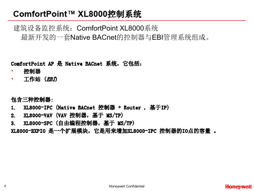
• Features: ☼ The XL8000-VAV represents a series of native BACnet controllers without builtin actuator for VAV applications. ☼ Designed with 32 bit microprocessor, built in Real Time Clock ☼ On-board airflow sensor, Compatible with Honeywell T7460 and T7560 Wall Modules ☼ Connects to XL8000-IPC on one of the three BACnet MSTP channels ☼ Easy data sharing with peer to peer communication on field communication bus (BACnet MSTP channels) ☼ Support standard VAV control applications – and -- is fully field programmable with ComfortPoint Studio
Native BACnet 单一控制器,设计为 FCU使用,通用的IO点,可以监视和简 单的空调冷水阀的控制。连接到 XL8000-IPC 控制器上3个 MSTP通道 中的其中一个,支持标准的FCU应用程 序。客户可以自己自由编程。
霍尼韦尔气体传感器使用说明书

12CONTENTS1. INTRODUCTION .........................................................22. ASSOCIATED DOCUMENTATION ..............................23. SAFETY .......................................................................3 3.1 Warnings ...........................................................3 3.2 Precautions .......................................................34. OPERATIONS .............................................................4 4.1 Installation ........................................................4 4.2 Calibration .. (5)4.3 Fault finding (8)5. MAINTENANCE ..........................................................9 5.1 Changing the electrochemical cell and internal filter ......................................................9 5.2 Changing the external hydrophobic assembly 10 Appendix A - Specifications ..............................11 Appendix B - Glossary ......................................12 Appendix C - Main features . (13)Appendix D-Spare parts (14)APPENDIX A - SPECIFICATIONSAPPENDIX B - EC DECLARATION APPENDIX C - MAIN FEATURESAPPENDIX D - SPARE PARTSmanufacturer’s trademark & addressCE mark - conforms to all applicable European directivescertification numberexplosion protection mark and equipment group & categoryCertification label3745896104. OPERATIONS5. MAINTENANCE4.3FAULT FINDINGSensor reads non-zero all the time:• Gas could be present, ensure that there is no target gas in the atmosphere. Background or other volatile organic gases, eg. solvents, can interfere with the operation of the sensor.Sensor reads non-zero when no gas is present:• adjust the zero on the control card.Sensor reads low when gas is applied:• adjust the span on the control card.• for oxygen versions, check that the neoprene plug has been removed from under the plastic retainer.Sensor reads high when gas is applied:• adjust the span on the control card.Sensor reads zero when gas is applied:• check the wiring.• check the dust protection cap has been removed.• check that the sensor is not obstructed.• replace the sensor if failure is suspected.• for oxygen versions, check that the neoprene plug has been removed from under the plastic retainer.Cannot adjust span or zero at control card:• refer to the technical handbook.5.1 CHANGING ELECTROCHEMICAL CELL ANDINTERNAL FILTER1. Unscrew and remove the grey plastic retainer (or accessory if fitted) from the sensor.2.Remove the old internal hydrophobic assembly bypushing against the snap fit, through one of the retaining slots, with a small flat bladed screwdriver. The assembly will pop out. Do not attempt to lever the assembly out as this may damage the housing.3. Remove the internal metal gauze insert.4.Open the enclosure by unscrewing the sensor capassembly from the sensor main body, ensuring that the electrochemical cell does not rotate with the cap.5a.ToxicGently pull the old electrochemical cell from the pcb. (Dispose of this in accordance with the local regulations).5b.OxygenFor oxygen Sensepoint, unscrew the old cellconnections. Support the screw pillars during removal and refitting of the oxygen cell screws.6. Remove the new cell from its packaging and remove the shorting link across the base of cell.7a. Plug the new cell into the pcb. (toxic cell)7b. Screw in the new cell via the metal tabs. (oxygen cell)8. Screw the sensor cap assembly back onto the sensor main body.9. Fit the new internal metal gauze assembly.10.Fit the new internal hydrophobic assembly.Note: The sensor should now be calibrated. See Section 4.2ATEX SPECIAL CONDITIONS FOR SAFE USEThe detector head must be protected from impact.The detector head must not be used in atmospheres containing greater than 21% oxygen. The integral supply leads must be mechanically protected and terminated in a terminal or junction facility suitable for the areaclassification if the installation. The terminal box and any shrouding metal work (when used) must be effectively earthed. The detector head is considered to present a potential electrostatic risk and must not be located in high air flows or rubbed. The front cover must not be removed when a dust hazard exists and must be fully tightened when replaced. The detector head is designed to be mounted vertically with the gas sensor facing downwards.4.1 INSTALLATIONThe Unit should be fitted to a junction box certified Ex d or Ex e, and fitted with an approved cable gland and connector block. The sensors should be fitted to a tapped hole within the enclosure and locked in place with a locknut if the parallel thread version is being used. Cabling should be multicore, two wires plus screen, conductor size 2.5mm 2 (14AWG) max. Sensors are supplied pre-calibrated.The apparatus should be installed in a location free from dusts and direct heat sources.For optimum protection against water ingress ensure that the sensor is installed facing downwards.Installation is to be performed by a qualified installation engineer, with the power to the unit disconnected.For oxygen versions, remove the neoprene stopper and snap the RFI screen and internal hydrophobic assembly (supplied separately) into place (page 10).See the technical handbook for details of installation in a duct or in forced air conditions.4. OPERATIONS4. OPERATIONS4. OPERATIONS3.1 WARNINGS•T his apparatus is not suitable for use in oxygenenriched atmospheres (>21%V/V). Oxygen deficient atmospheres (<6%V/V) may suppress the sensor output.• Refer to local or national regulations relative to installation at the site.• The operator should be fully aware of the action to be taken if the gas concentration exceeds an alarm level.• The ECC (electrochemical cell) contains a small quantity of acid.• I nstallation should consider not only the best placingfor gas detection related to potential leak points, gas characteristics and ventilation, but also where the potential of mechanical damage is minimized or avoided.• Only assessed by ATEX for ignition hazards• Electrostatic risk - Do not rub or clean with solvents. Clean with a damp cloth. High velocity airflows and dusty environments can cause hazardous electrostatic charges.3.2 CAUTIONS• Exposures to gas above the design range of thesensor may require the sensor to be re-calibrated.•Do not modify or alter the sensor construction as essential safety requirements may be invalidated.• Install Sensepoint using certified Ex e or Ex d junction box, connectors and glanding.•Sensors should be disposed of in accordance with local disposal regulations. Materials used:Sensor: Fortron® (PPS-polyphenylene sulphide), Cell: PPO (modified polyphenylene oxide).• T his equipment is designed and constructed as toprevent ignition sources arising, even in the event of frequent disturbances or equipment operating faults. The electrical input is protected with a fuse.• Do not access the interior of the Sensepoint gas sensor when hazardous (explosive) gas or dust is present. Ensure o-ring is fitted and body is fully tightened when gas cell is replaced.3. SAFETY4.2 CALIBRATIONSensepoint for toxic gas detection is suppliedpre-calibrated, however, for increased accuracy in specific applications, on-site calibration is recommended.Re-calibration should only be attempted by qualified service personnel. Calibration should only be attempted after the sensor has been installed and powered for a time exceeding the warm up time (Table 1).Gas Range Recommended Warm Application Operating Temp.Test up Time MIN. MAX.Concentration TimeH 2S 0 to 20 ppm 10 ppm 3mins 3 mins -20°C +50°C H 2S 0 to 50 ppm 20 ppm3mins 3 mins -20°C +50°C H 2S 0 to 100 ppm 50 ppm3mins 3 mins -20°C +50°C CO0 to 100 ppm 50 ppm3mins 3 mins -20°C +50°C CO 0 to 200 ppm 100 ppm 3mins 3 mins -20°C +50°C CO 0 to 500 ppm 250 ppm 3mins 3 mins -20°C +50°C Cl 2 0 to 5 ppm 3 ppm 5mins 10 mins -20°C +50°C Cl 2 0 to 15 ppm 10 ppm 5mins 10 mins -20°C +50°C O 20 to 25% v/v19% v/v 5mins 1 mins -15°C +40°C NH 3 0 to 50 ppm 25 ppm3mins 10 mins -20°C +40°C NH 3 0 to 1000 ppm 500 ppm3mins 10 mins -20°C +40°C H 2 0 to 1000 ppm 500 ppm 3mins 3 mins -5°C +40°C H 20 to 10000 ppm 3000 ppm3mins 3 mins -5°C+40°CSO 2 0 to 15 ppm 10 ppm 3mins 5 mins -15°C +40°C SO 2 0 to 50 ppm 20 ppm3mins 5 mins -15°C +40°C NO 0 to 100 ppm 50 ppm12hrs 5 mins -5°C+40°CNO 2 0 to 10 ppm5 ppm1hr5 mins-15°C +40°CTable 1:5. MAINTENANCESCREENSCREENSENSORWiring connections are:-The unit requires a nominal 18 to 30V, 30m current-loop-powered supply.First zero the control system with no gas present on the sensor. If target gas is suspected to be in the vicinity of Sensepoint, flow clean air over the sensor using a flow housing (see below).Fit a flow housing and connect a cylinder of either air, for a zero, or a known concentration of gas (approximately 50% FSD) to the flow housing using nylon or PTFE tubing. Tubing lengths should be kept to a minimum to avoidextending the speed of response. Connect the outlet of the flow housing to a safe exhaust area. Pass the gas through the flow housing at a flow rate of approximately1 l to 1.5 l per minute. Allow the sensor to stabilise. When gassing with air, adjust the control card to indicate zero. For span, the control card should be adjusted to indicate the concentration of the target gas being applied. Remove the flow housing and the gas supply.Note: for oxygen, the span gas is normally air at 20.8%v/vO 2. The control card should be adjusted to indicate this when the sensor is in either clean ambient air, or in a flow of 20.8%v/v O 2 in nitrogen from a cylinder. A zero adjustment is not normally required, however it is recommended that the alarm levels are tested using a cylinder of a lower concentration of oxygen in nitrogen.See Table 1 for details of concentrations and times to be used. If the controller cannot be spanned, consult the technical handbook.For calibration using the Weather Protection in high flow applications refer to the technical handbook.Plastic retainerExternal hydrophobic barrier Main body of sensorOxygen cellInternalhydrophobic assembly Sensor cap Toxicelectrochemical cellRFI screen / metal gauze11. Replace the grey plastic retainer or accessory.12. In the event of an apparatus failure, return unit to Honeywell Analytics Ltd.5.2 CHANGING THE EXTERNAL HYDROPHOBIC BARRIERRemove the plastic retainer (or accessory). Remove the old external hydrophobic barrier and replace with the new one. Replace the plastic retainer.4. OPERATIONS。
霍尼韦尔报警系统设备参数(2015版)
可以通过短信进行布/撤防操作。
支持劫持码功能。
LED灯指示主机状态和网络强度。
蜂鸣器提示。
1.7
防区数:
6个基本防区
控制特性:
15个用户密码(包括1个系统主密码及1个副主码)
防拆保护
LED或LCD键盘控制,最多接4个键盘
事件回读功能:255条事件记录,可实现掉电存储, 通过ALPHA PLUS II键盘查看
支持多达127个无线防区扩展,最多使用2个5800系列的无线接收机。(当使用有线防区/轮询回路的扩展防区时无线防区将少于127个)
可分为8个独立控制的子系统
提供32条键盘宏指令,每个命令最多32个字符
时间日志,VISTA-128BPT能保存512条事件记录,VISTA-250BPT能保存1000条事件记录
报警系统设备参数
目
录
1.
1.1
防区特性:
6个基本防区,均带有末端电阻监控。防区反应时间为300毫秒,防区3可设为反应时间为10毫秒的快速反应防区键盘上附带有紧急按键防区不具防区扩充性。
控制特性:
支持1个系统主密码及3个二级用户密码
防拆保护
可通过61 48CH键盘对系统进行编程控制
输出功能:
1.键盘内置蜂呜器,作为故障、报警等事件提示
100条事件记录
内置电话线检测
遥控编程:
可通过COMPASS软件对主机遥控编程
尺寸规格
318W ×368H × 76Dmm
适用键盘:
6148CH、6160
扩展模块:
1)4219,8防区模块,
2)4229,8防区模块,带两个继电器输出;
霍尼韦尔 EX30 扫描采集设备说明书

• Near and Extended FlexRange™ read ranges of 10 cm to 20 m [4 in to 66 ft]allow both near and far barcode reading in the same device.• MIPI interface provides compatibility with newer processors.• Patented, embedded, auto-focus lensmechanism enables fast, aim-and-scan operation, allowing job efficiency.• Compact dimensions of 13 mm x 30,5 mm x 22,2 mm [0.51 in x 1.2 in x 0.87 in] allow easier fit into slimmer mobile device designs.• Fully compatible with Honeywell’s N670X, N660X, and N360X Series scan engines, reduces integration time and increases design flexibility.• Flexible choice of decoder software or hardware (Honeywell Gen7 DB Decoder Board) options allow integration into both OS and non-OS supported devices.Extended FlexRange EX30 2D Scan EngineThe Extended FlexRange EX30 2D ScanEngine for warehouse and distribution center operations seamlessly reads barcodes from 10 cm to 20 m [4 in to 66 ft] using the latest technology for a fast auto-focus mechanism.Warehouse and distribution center operation managers need barcode scanning solutions that can read barcodes at close distances as well as those farther away, such as package labels on shelves as high as 10 cm to 20 m [4 in to 66 ft]. The EX30 answers this key requirement by enabling a wide angle read range of 42° at close distances and up to 20 m [66 ft].Operators reading barcodes at both near and far distances expect to switchseamlessly between both operations. The Extended FlexRange EX30 uses the latest technology for a fast auto-focus lens mechanism that provides the focus change multiple times faster than its predecessor. At this level of performance, the operator feels no latency in reading across the entire distance range, allowing an efficient and comfortable work pace.The Extended FlexRange EX30's electrical interface is fully compatible withHoneywell's N670X Series, N660X Series, and N360X Series fixed-focus, compact scan engines. This compatibility provides customers with a complete barcodescanning performance offering, ranging from better to best, that fits into the same mobile device, keeping design time and resources to a minimum. The Extended FlexRange EX30 is available with either a parallel or the MIPI interface, now commonly used with the newest generation of processors.The Extended FlexRange EX30 may easily be embedded into mobile devices running under an OS by using the resources of the device's main processor. Honeywellsupports its customers with integrating decoder software into their solutions, saving the cost of ownership by eliminating hardware and also enhancing performance by using the main processor's power.EXTENDEDFLEXRANGE™ EX302D Scan Engine, Undecoded, Auto-FocusThe Extended FlexRange EX30 may also be powered by the new Honeywell Gen7 DB Decoder Board, allowing easy integration into non-OS devices such as drones, mobile accessories and sleds.POTENTIAL APPLICATIONSBoth near and far barcode scanning in same device for use in warehouse and distribution centers.FEATURES AND BENEFITSEXTENDED FLEXRANGE™ EX30 2D SCAN ENGINE | /optical-sensing |21 Based on MIL-HDBK-217F (releasedDecember 1, 1991). The calculation is based on the part count method for the Ground Benign (GB) environmental conditions.2 Barcode quality and environmental conditions may affect performance.3 Code resolution: 1D: 13 mil, 2D: 20 mil 1. 4 Extreme temperatures will reduce the depth of field. 5 Extreme ambient light conditions will reducethe depth of field.FIGURE 1. LASER AIMEREXTENDED FLEXRANGE™ EX30 2D SCAN ENGINE Technical Specifications007629-3-EN US | 3 | 10/20© 2020 Honeywell International IncFind out moreTo learn more about Honeywell scan engines and barcode decoding software, visit /optical-sensingHoneywellSensing and Internet of Things 830 East Arapaho Road Richardson, TX 75081NOTICEMISUSE OF DOCUMENTATION• The information presented in this datasheet is for reference only. Do not use this document as a product installation guide.WARRANTY/REMEDYHoneywell warrants goods of its manufacture as being free of defective materials and faulty workmanship during the applicable warranty period. Honeywell’s standard product warranty applies unless agreed to otherwise by Honeywell in writing; please refer to your order acknowledgment or consult your local sales office for specific warranty details. If warranted goods are returned to Honeywell during the period of coverage, Honeywell will repair or replace, at its option, without charge those items that Honeywell, in its sole discretion, finds defective. The foregoing is buyer’s sole remedy and is in lieu of all other warranties, expressed or implied, including those of merchantability and fitness for a particular purpose. In no event shall Honeywell be liable for consequential, special, or indirect damages.While Honeywell may provide application assistance personally, through our literature and the Honeywell web site, it is buyer’s sole responsibility to determine the suitability of the product in the application.Specifications may change without notice. The information we supply is believed to be accurate and reliable as of this writing. However, Honeywell assumes no responsibility for its use.。
Honeywell T7460A B C D E F 浓盐温度传感器技术数据手册说明书

® U.S. Registered TrademarkCopyright © 2011 Honeywell Inc. • All Rights ReservedEN1B-0291GE51 R1211BT7460A,B,C,D,E,FWALL MODULESHONEYWELL EXCEL 5000 OPEN SYSTEMINSTALLATION INSTRUCTIONSBEFORE INSTALLATIONAll wiring must comply with local electrical codes andordinances or as specified on installation wiring diagrams. Wall module wiring can be sized from 16 to 22 AWG (1.5 to 0.34 mm 2), depending on the application. The maximum length of wire from a device to a wall module is 1000 ft (305 m). Twisted-pair wire is recommended for wire runs longer than 100 ft (30.5 m).COVER DISASSEMBLYThe cover of the wall module is fixed in place using a tab located on the underside of the unit; to disassemble the cover and the sub-base, see Fig. 1.PRESSLIFTFig. 1. Cover disassemblyTable 1. Features of T7460 VersionsSensorSetpoint Bypass/ LED Fan speedT7460A- - - T7460B- - T7460C- T7460D- 5-position T7460E3-position T7460F 5-positionINSTALLATIONThe T7460B,C,D,E,F packages include two setpoint dials.By default, the “Celsius Relative” type is mounted. This can be easily replaced with the “Celsius Absolute” type by pulling the one dial off and inserting the other one.Mount the T7460A,B,C,D,E,F Wall Modules on an inside wall approximately 54 in. (1.3 m) from the floor (or in the specified location) to allow exposure to the average zone temperature.NOTE: Maintain a mounting clearance of approx. 4 in.(10 cm) to the left-hand side of the module in order to allow a free airflow for the temperature sensor and accessibility of the setpoint dial.Do not mount the wall modules on an outside wall, on a wall containing water pipes, or near air ducts. Avoid locations that are exposed to discharge air from registers or radiation from lights, appliances, or the sun.The T7460D,E,F should not be connected to con-trollers that do not support fan operation (i.e., the W7751, W7762, W7763, W7704, and XFC2xxxx / XFC3xxxx).When used with CPO-FB22344R-xxx controllers, either setpoint override or fan-speed adjustment is supported.Keep wiring at least 1 ft (305 mm) away from large inductive loads such as motors, line starters, lighting ballasts, and large power distributionpanels. Run wall module wiring separately from 50 Vac or greater power wiring. The wall modules can be mounted on a 60-mm wall outlet box using No. 6 (3.5-mm) screws or on a wall (see Fig. 2 and Fig. 5). When mounting directly on a wall, use the typeof screws appropriate for the wall material.Fig. 2. Bore-holes for T7460 wall modules in in. (mm) See Fig. 3 for mounting dimensions.NOTE: Graphics depict E/F model. Dimensions are thesame for all six models.T7460A,B,C,D,E,F WALL MODULES – INSTALLATION INSTRUCTIONSEN1B-0291GE51 R1211B 2Fig. 3. T7460A,B,C,D,E,F dimensions in in. (mm)Mounting Procedure1. Disassemble the cover as is shown in Fig. 1.2. (T7460B,C,D,E,F, only) Remove the setpoint dial bypulling it off.3. a) Mount the wall module onto the wall outlet box, orb) bore wall holes as is specified in Fig. 2 and mount the wall module with appropriate screws.4. Connect the wires to the terminal block according to thespecifications in section “Wiring”.5. (T7460B,C,D,E,F only) Insert the setpoint dial and turnit clockwise as far as possible.6. (T7460B,C,D,E,F only) Make sure that the dial'sposition is such that the 30 (Celsius absolute scale) or the +5 (Celsius relative scale) point to the right-handFig. 4. Mounting position of setpoint dial7. (T7460B,C,D,E,F, only) If the dial does not have thecorrect position, pull the dial off again and reinsert it with the correct orientation.8. Remount the cover as depicted in Fig. 5 and make surethat the tab on the underside engages.Fig. 5. Mounting cover of T7460 wall modulesWiringAttach the wires from the device sensor terminals to the appropriate wall module terminals and set the jumpers according to the connected controller. See Fig. 6 through Fig. 8. IMPORTANTScrew type terminal blocks are designed to accept no more than one 16 AWG (1.5 mm 2) conductor.Wire the terminal blocks as follows:1. Strip 3/16 in. (5 mm) of insulation from the conductor.2. Insert the wire in the required terminal location andtighten the screw to complete the termination. 3. Verify jumper setting with Fig. 8 and wall module wiringwith Fig. 6 and Fig. 7.T7460A,B,C,D,E,F WALL MODULES – INSTALLATION INSTRUCTIONS3 EN1B-0291GE51 R1211BTable 2. Wiring terminal references for non-Excel 10/12 devicessignalT7460A terminalT7460B terminalT7460C terminalExcel 800 XF82x terminal (example) Excel 500 XF52xB terminal (example) Excel 500 XFL52x terminal (example) Excel 100 terminal (example) Excel 50 terminal (example) Excel 20 terminal (example) CPO-FB22344R terminal (example) Smart I/O XFC2 / XFC3 terminal (example) sensor signal1 1 2XF821: 1 (AI)XF521: 1 (AI) XFL521: 1 (AI) 1 (AI) 33 (AI)19 (AI)39 (AI) 11 (AI) COM/GND 3 3 1XF821: 11(AI GND) XF521: 2 (AI GND) XFL521: 18 (AI GND) 55 (GND) 34 (AI GND) 20 (AI GND) 40 (AI GND) 10 (AI GND) SETPT -- 2 3 XF821: 2 (AI) XF521: 3 (AI) XFL521: 2 (AI) 2 (AI) 35 (AI) 21 (AI) 41 (AI) 14 (AI) BYP/FAN (no fan)----4XF823: 1 (DI)XF523: 1 (DI) XFL523: 1 (DI) 13 (DI) 23 (DI) 34 (DI) 36 (DI) 6 (DI) BYP/RTN -- -- 6XF823: 13(DI GND) XF523: 14 (DI GND)XFL523: 18 (DI GND) 56 (GND) 24 (DI GND) 18 (COM) 37 (DI GND) 5 (DI) LED(10Vdc/3mA permanent) ----5XF822: 1 (AO) XF522: 1 (AO)XFL522: 1 (AO)37 (AO)15 (AO)12 (AO)19 (AO)32 (AO)LED/RTN(0Vdc = LED OFF, 10Vdc = LED ON)-- -- 7 XF822: 2 (AO) XF522: 3 (AO) XFL522: 2 (AO) 38 (AO) 17 (AO) 13 (AO) 17 (AO) 35 (AO)signalT7460D terminalT7460D,E,F terminalExcel 800 XF82x terminal (example) Excel 500 XF52xB terminal(example) Excel 500 XFL52x terminal(example) Excel 100 terminal (example) Excel 50 terminal (example) Excel 20 terminal (example) CPO-FB22344Rterminal (example)sensor signal22XF821: 1 (AI)XF521: 1 (AI) XFL521: 1 (AI) 1 (AI) 33 (AI) 19 (AI) 39 (AI) COM/GND 1 1XF821: 11(AI GND) XF521: 2 (AI GND) XFL521: 18 (AI GND) 55 (GND) 34 (AI GND) 20 (AI GND) 40 (AI GND) SETPT 3 3 XF821: 2 (AI) XF521: 3 (AI) XFL521: 2 (AI) 2 (AI) 35 (AI) 21 (AI) 41 (AI) BYP/FAN (no fan)44XF821: 3 (AI)XF521: 5 (AI) XFL521: 3 (AI) 3 (AI) 37 (AI) 23 (AI) alternatively toSETPT BYP/RTN 6 6XF821: 13(AI GND) XF521: 6 (AI GND) XFL521: 20 (AI GND) 56 (GND) 38 (AI GND) 24 (AI GND) alternatively toSETPT LED(10Vdc/3mA permanent) --5XF822: 1 (AO)XF522: 1 (AO)XFL522: 1 (AO)37 (AO)15 (AO)12 (AO)19 (AO)LED/RTN(0Vdc = LED OFF, 10Vdc = LED ON)-- 7 XF822: 2 (AO) XF522: 3 (AO) XFL522: 2 (AO) 38 (AO) 17 (AO) 13 (AO) 17 (AO)NOTE: In the case of Excel 10/12 wiring, please refer to the respective Excel 10/12 Installation Instructions.NOTE: In the case of the T7460A,B,C, bypass signaling is via digital input. In the case of the T7460D,E,F, bypass signaling(which includes fan-speed signaling) is via analog input.Jumper SettingsSee also Fig. 8. The jumpers on the PCB of the T7460C,D,E,F must be set according to the type of controller connected.Jumper Setting 1 for W77xx Const. Vol. Air Handling Unit W7750A,B (Smart) Variable Air Volume W7751B,D,F,H Fan Coil Unit (FCU2) W7752D,E,F,G Fan Coil Unit (FCU3) W7754 Remote Input/Output Device W7761AHydronic W7762A,B Chilled Ceiling W7763C,D,E Excel 12 W7704xxJumper Setting 2 for W7753 Unit VentilatorW7753Jumper Setting 3 for XL500 Excel 800 XCL8010AExcel 500 XC5010x, XC5210x Excel 100 XL100x Excel 50XL50xxxxExcel 20 XL20xCPO-FCU CPO-FB22344R-xxx Smart I/O XFC2xxxx/XFC3xxxxT7460A,B,C,D,E,F WALL MODULES – INSTALLATION INSTRUCTIONSFig. 6. Wiring diagram for T7460A,B Wall ModulesFig. 7. Wiring diagram for T7460C,D,E,F Wall Modules EN1B-0291GE51 R1211B 4T7460A,B,C,D,E,F WALL MODULES – INSTALLATION INSTRUCTIONS5 EN1B-0291GE51 R1211BFig. 8. Jumper settings for T7460C,D,E,F Wall ModulesACCESSORIEST7460-LONJACKThe T7460-LONJACK is a small board and allows easy access to L ON W ORKS or BACnet via the correspondingly wired wall module (apply appropriate wiring guidelines for L ON W ORKS or BACnet networks, as the case may be). The T7460-LONJACK provides an additional 3.5 mm jack socket for a 3.5 mm jack plug.Order quantity: set with 5 piecesFig. 9. T7460-LONJACKMountingRemove the setpoint dial and put in the T7460-LONJACK as shown in the following:Fig. 10. Mounting T7460-LONJACKT7460-LIMITERThe T7460-LIMITER can be used to adjust the setpoint dial to particular setpoints.Put the limiters approximately opposite the setpoints you want to adjust. In the following example, the setpoints are at about 18 and 27 C. Order quantity: set of 100 piecesFig. 11. Mounting T7460-LIMITER(S)T7460A,B,C,D,E,F WALL MODULES – INSTALLATION INSTRUCTIONSManufactured for and on behalf of the Environmental and Combustion Controls Division of Honeywell Technologies Sàrl, Rolle, Z.A. La Pièce 16, Switzerland by its Authorized Representative: Automation and Control SolutionsHoneywell GmbHBöblinger Strasse 1771101 Schönaich, GermanyPhone: (49) 7031 63701Fax: (49) 7031 637493Subject to change without notice. Printed in GermanyEN1B-0291GE51 R1211B / 95-7610-4 rev. Dec. 2011 Printed in Germany。
Honeywell 压力传感器(Jackson Union压力传感器)产品说明书

(casing and cementing) are vital oil and gas processes that utilize pressure sensors for measurement and monitoring functions.APPLICATIONSHoneywell Wing Union pressure sensors (also known as Hammer Union pressure sensors outside of the United States) are widely used by oil and gas companies to measure pressure level changes in media circulation systems.Oil Mud LoggingFor example, oil mud loggingapplications (see Figure 1) require a series of pressure sensors to be connected to the drilling apparatus and installed in specialized equipment to monitor or “log” the drill’s activity. Logging While Drilling (LWD) and Measurement While Drilling (MWD)pump into the well), mud pumps (for pressure monitoring of incoming and outgoing media to protect the mudpump and drill bit), and return line choke manifold (for pressure monitoring of the return line carrying the mud plus cuttings).During the mud logging process, pumps send drilling media throughout the circulation system, down to the drilling bit, and then return the bit’s cuttings to the surface for analysis and disposal. Honeywell’s wing union/hammer union pressure sensors help detect pressure level changes in the media circulation system, which can indicate changing conditions being encountered downhole by the drill bit, thus allowing the operator to quickly make adjustments to the drilling mixture pressure or drilling process as needed.today’s oil and gas industry, used for many types Models 434, 435, 437 Wing Union/ Hammer Union Pressure TransducerPRESSURE SENSORS FOROIL & GASApplication NoteFracturing, Acidizing, and Cementing Honeywell’s Wing Union/Hammer Union pressure sensors are also used during fracturing, acidizing, and cementing applications for similar pressure monitoring and control purposes.SOLUTIONSHoneywell Wing Union/Hammer Union Pressure Sensors are built ruggedand oilfield tough to stand up to the rigorous demands of oil and gas drilling applications and environments. They have the sensitivity to ensure precise, reliable measurements every time, optimize drilling operation, reduce downtime, and maximize productivity. Durable ConstructionModels 434, 435, and 437 are constructed on Honeywell’s time proven all-welded, one-piece design, with the sensor diaphragm and Weco® 1502, 2202 Wing Union compatible fitting form factor machined as one part. This one-piece design provides a hermetically sealed unit, reducing the chanceof media leakage into the sensitive electronic components, and increasing overall reliability. The isolated, pressure sensing diaphragm minimizes zero-shift during hammer up and also eliminates long term, signal drift in the field, making it easier to install and providing reliable pressure readings over time.The sensor diaphragm is machined from Inconel® 718, which provides additional durability with highly abrasive and corrosive media, and is weldedto the main stainless steel body. The stainless steel electrical connection provides enhanced secondary pressure containment, with multiple electricalconnector options from which to choose.Optional 1-Wire or 2-Wire ShuntCalibrationModels 434, 435, and 437 providean optional 1-wire or 2-wire shuntcalibration. When a customer sends asignal to the wing union/hammer unionfrom their instrumentation, anothersignal will be returned to validate thefunctionality of the unit. This providesconfidence in the pressure readingsduring normal operation.Optional Protective CageModels 434, 435, and 437 are alsoavailable with an optional protectivecage which provides extra electricalconnection protection and durability.Various Accuracy Levels• Model 434: 0.2 %FSS BFSL• Model 435: High accuracy±0.1 %FSS BFSL orstandard accuracy ±0.2 %FSS BFSL• Model 437: Standard accuracy±0.2 %FSS BFSLModel 437 feature a wider aperturedesign than the other models that isuseful for customers utilizing moreviscous media in certain applications,enabling uniform flow of differentviscous media through the criticalsensing area and helping to maintainconsistent accuracy.*Best Fit Straight LineBENEFITS• Higher ±0.1 %FSS BFSL Accuracy(Model 435): Provides additionalconfidence in the actual measuredpressure value, particularly forsmaller changes in pressure, thusallowing the operator to makequicker adjustments to drillingoperations for more precise controland increased efficiency duringextraction• Wider Aperture Design (Model 437):Wider than Models 434 and 435,helping to prevent media cloggingwhen using more viscous mediablends• Reliability/Durability: All-welded,hermetically sealed, stainless steelconstruction with Inconel® 718wetted parts isolate corrosive orabrasive drilling media from sensitiveinternal electronics; materials retainstrength in higher temperatures toprovide reliable performance underdemanding conditions; shock andvibration tested, intrinsically saferating• Easy Installation/Serviceability:Designed for quick field installation,including horizontal or verticalmounting; field-repairableconnectors; zero and spanadjustments can be accessed byremoving the electrical connector,thus preventing ingress failures anddeterring tampering; 1-wire or 2-wireshunt calibration allow the user todetermine if the wing union/hammerunion is still functional in the field,or if it has to be removed for service/calibration.2 APPLICATION NOTE | Wing Union/Hammer Union Pressure Transducers | /astAPPLICATION NOTE | Wing Union/Hammer Union Pressure Transducers | /ast 3SELECTION GUIDEHoneywell offers three models from which to choose:üüü üüü üüü* Note: See Wing Union pressure sensor datasheet for more agency approval classifications.For more information about Wing Union/Hammer Union pressure sensors, including nomenclature and dimensional drawings, see our datasheet.008875-6-EN | 6 | 10/21© 2021 Honeywell International Inc. All rights reserved.HoneywellAdvanced Sensing Technologies 830 East Arapaho Road Richardson, TX 75081WARRANTY/REMEDYHoneywell warrants goods of its manufacture as being free of defective materials and faulty workmanship during the applicablewarranty period. Honeywell’s standard product warranty applies unless agreed to otherwise by Honeywell in writing; please refer to your order acknowledgement or consult your local sales office for specific warranty details. If warranted goods are returned to Honeywell during the period of coverage, Honeywell will repair or replace, at its option, without charge those items that Honeywell, in its sole discretion, finds defective. The foregoing is buyer’s sole remedy and is in lieu of all other warranties, expressed or implied, including those of merchantability and fitness for a particular purpose. In no event shall Honeywell be liable for consequential, special, or indirect damages.While Honeywell may provide application assistance personally, through our literature and the Honeywell web site, it is buyer’s sole responsibility to determine the suitability of the product in the application.Specifications may change without notice. The information we supply is believed to be accurate and reliable as of this writing.However, Honeywell assumes no responsibilityfor its use.FOR MORE INFORMATIONHoneywell Advanced Sensing Technolo-gies services its customers through a worldwide network of sales offices and distributors. For application assistance, current specifications, pricing, or the nearest Authorized Distributor, visit /ast or call:USA/Canada +302 327 8920Latin America +1 305 805 8188Europe +1 302 327 8920Japan +81 (0) 3-6730-7152Singapore +65 6355 2828Greater China+86 4006396841。
霍尼韦尔DCS资料翻译-控制器-C200(中译文)

Experion过程知识系统(PKS)Experion平台基于CEE的控制器规范和技术数据EP03-300-210210版修订日期:2004年11月版本:1.0Experion基于CEE的控制器规范和技术数据目录页码引言 (1)Experion平台 (1)统一的合作体系结构 (1)体系结构概述 (2)Experion基于CEE的控制器概述 (3)通信基础结构 (5)容错以太网概述 (5)ControlNet概述 (5)以太网概述 (5)功能描述 (6)控制执行环境 (6)控制策略的生成 (7)控制功能 (9)控制库 (11)21CFR第11部分 (12)Experion过程模拟 (13)过程迁移 (13)技术规范和分级 (15)控制器环境与符合性认证 (15)控制处理器模块硬件的技术规范 (16)ControlNet技术规范 (17)控制网电缆 (18)功能块类型 (20)Control Builder技术规范 (21)网络技术规范 (22)控制执行环境技术规范 (24)控制器通信性能 (25)控制器冗余规范 (28)I/O模块和Fieldbus的能力 (28)C200控制处理器处理和内存资源 (31)C200模拟环境规范 (34)型号 (36)型号一览示例 (36)控制器、机架、电源和通信模块 (41)其它硬件 (41)电缆和连接器 (42)控制器软件 (43)模拟系统软件 (45)修订状态修订内容变更符号说明:A——增加D——删除M——修改产管理相统一,帮助流程生产商增加盈利和生产率。
这是唯一一个将焦点集中在人身上的过程自动化系统,充分利用了人们所掌握的知识。
Experion通过搜集和整合整个设备的过程及业务数据来提高经营成绩和心境的安宁,使得信息和知识在需要的时间和地点即时可用,从而使人们能作出正确的决策。
Experion的核心是Experion平台,该平台提供了一个基础,可将所有过程控制及安全管理(包括非霍尼韦尔系统)并入一个单独统一的体系结构。
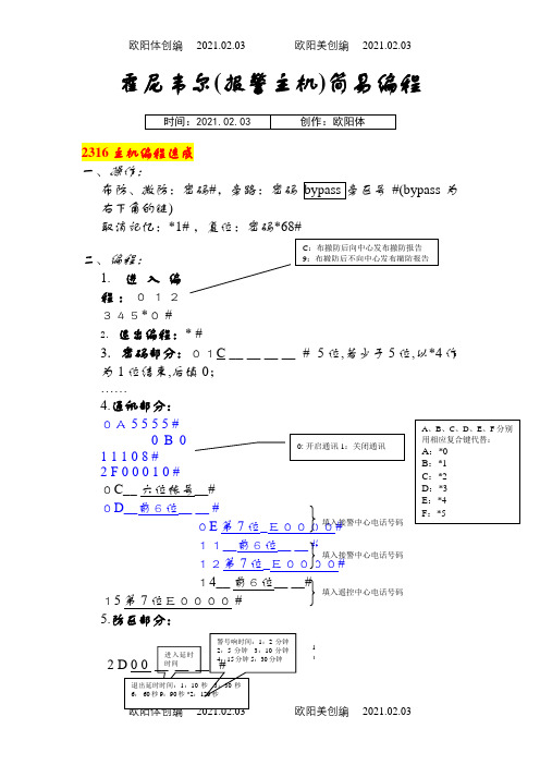
霍尼韦尔(报警主机)简易编程之欧阳体创编
2021.02.03霍尼韦尔(报警主机)简易编程2316主机编程速成 一、操作:布防、撤防:密码#,旁路:密码 #(bypass 为右下角的键)取消记忆:*1# ,复位:密码*68#二、编程:1. 进入编程:012345*0 #2. 退出编程:* #3.密码部分:01C __ __ __ __ # 5位,若少于5位,以*4作为1位结束,后填0; ……4.通讯部分: 0A00 14__ 前6位__ __#15第7位E0000 # 5.防区部分:11C :布撤防后向中心发布撤防报告 9:布撤防后不向中心发布撤防报告填入遥控中心电话号码欧阳体创编 2021.02.03 欧阳美创编 2021.02.03一防区1F 12 1 __ __ 3 #二防区2 0 12 1 __ __ 3 # 三防区2 1 12 1 __ __ 3 #十防区4 A 12 1 __ __ 3 #四防区 22 12 1 __ __ 3 #十一防区4 B 12 1 __ __ 3 # 五防区 23 12 1 __ __ 3 #十二防区4 C 12 1 __ __ 3 # 六防区 24 12 1 __ __ 3 #十三防区4 D 12 1 __ __ 3 # 七防区 25 12 1 __ __ 3 #十四防区4 E 12 1 __ __ 3 # 八防区 26 12 1 __ __ 3 #十五防区4 F 12 1 __ __ 3 # __ __ 3 #十六防区5 0 12 1 __ __ 3 # 一、操作:布防、撤防:密码# 旁路:密码 )取消记忆:*1#复位:密码*68# 关键盘音:*51#例如:布防、撤防:1234# 旁路:1234 #取消记忆:1234*1# 复位:1234*68#二、编程:1.进入编程:012345*0 # 2.退出编程:* # 3.密码部分:01__ __ __ __ # 密码必须四位……4.通讯部分:07111111#08001000# 09011100#0A5353#0B 六位用户帐号# 0 C #0 D E0000 # 警声:1.脉冲声 2.稳定声2.即时3.延时9.24小时填入接警中心电话号码填入接警中心电话号码0: 开启通讯1:关闭通讯A 、B 、C 、D 、E 、F 分别用相应复合键代替:A :*0B :*1C :*2D :*3E :*4F :*5欧阳体创编 2021.02.03 欧阳美创编2021.02.03 0 F #10E0000 # 12 # 13E0000 # 5.111220 #四防区 20 111220 # 五防区 21 111220 # 六防区 22 111420 # 238主机编程速成 一、操作:布防、撤防:密码#, 旁路:密码 )取消记忆:*1# ,复位:密码*68#例如:布防、撤防:1234# 旁路:1234 #取消记忆:1234*1# 复位:1234*68#二、编程:1.进入编程:012345*0 #2.退出编程:* #3.密码部分:01C 1 __ __ __ __ # 密码开头必须为1,写够5位,若为4位,以*4作为1位结束;……4.通讯部分:0A 555 5 #11填入遥控中心电话号码A 、B 、C 、D 、E 、F 分别用相应复合键代替:A :*0B :*1C :*2D :*3E :*4F :*5C :布撤防后向中心发布撤防报告 9:布撤防后不向中心发布撤防报告欧阳体创编 2021.02.03 欧阳美创编 2021.02.030 B 0 1 1 1 0 8 #2 F 0 0 0 1 #0C__ 六位帐号__# 0D__前6位__ __ #0E 第7位_11__前6位__ __ # 12第7位_E0000# 14__ 前6位__ __# 15第7位E0000 # 5.防区部分:__ __3 #二防区2 0 12 1 __ __ 3 # 三防区2 1 12 1__ __ 3 #四防区 22 12 1 __ __ 3 # 五防区 23 12 1 __ __ 3 # 六防区 24 12 1 __ __ 3 # 七防区 25 12 1 __ __ 3 # 八防区 填入接警中心电话号码 0: 开启通讯 1:关闭通讯 2.即时 3.延时 9.24小时填入遥控中心电话号码。
