SMC顶升转台组装线配件
微晟微电子 SG2800 系列高电压中等电流驱动器数组说明书
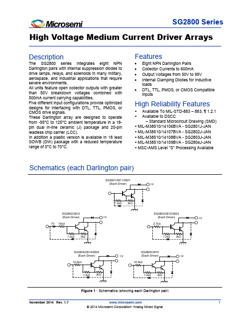
High Voltage Medium Current Driver ArraysSchematics (each Darlington pair)+VFigure 1 · Schematics (showing each Darlington pair)Features∙Eight NPN Darlington Pairs ∙Collector Currents to 600mA∙Output Voltages from 50V to 95V∙Internal Clamping Diodes for Inductive loads∙DTL, TTL, PMOS, or CMOS Compatible inputsHigh Reliability Features▪Available To MIL-STD-883 – 883, ¶ 1.2.1 ▪Available to DSCC– Standard Microcircuit Drawing (SMD) ▪MIL-M38510/14106BVA - SG2801J-JAN ▪MIL-M38510/14107BVA - SG2802J-JAN ▪MIL-M38510/14108BVA - SG2803J-JAN ▪MIL-M38510/14109BVA - SG2804J-JAN ▪MSC-AMS Level "S" Processing AvailableDescription The SG2800 seriesintegrates eight NPNDarlington pairs with internal suppression diodes to drive lamps, relays, and solenoids in many military,aerospace, and industrial applications that requiresevere environments. All units feature open collector outputs with greaterthan 50V breakdown voltages combined with 500mA current carrying capabilities. Five different input configurations provide optimized designs for interfacing with DTL, TTL, PMOS, orCMOS drive signals.These Darlington array are designed to operate from -55°C to 125°C ambient temperature in a 18-pin dual in-line ceramic (J) package and 20-pinleadless chip carrier (LCC). In addition a plastic version is available in 18 lead SOWB (DW) package with a reduced temperaturerange of 0°C to 70°C.SG2800 SeriesHigh Voltage Medium Current Mode PWM Controllerent Driver ArrayConnection Diagrams and Ordering InformationAbsolute Maximum Ratings1 Absolute Maximum Ratings1Thermal DataHigh Voltage Medium Current Mode PWM Controllerent Driver ArrayRecommended Operating Conditions1Selection GuideElectrical CharacteristicsElectrical Characteristics(Unless otherwise specified, these specifications apply over the operating ambient temperatures of -55°C ≤T A≤ 125°C, for the J & L devices and 0°C ≤ T A≤ 70°C, for the DW device. Low duty cycle pulse testing techniques are used which maintains junction and case temperatures equal to the ambient temperature.) Table 1 · SG2801 thru SG2804High Voltage Medium Current Mode PWM Controllerent Driver ArrayTable 2 · SG2811 thru SG2815Electrical CharacteristicsTable 3 · SG2821 thru SG2824High Voltage Medium Current Mode PWM Controllerent Driver ArrayParameter Test FiguresParameter Test Figures(See figure numbers in Electrical Characteristics Tables 1 to 3)Figure 2a I CEX Test Circuit Figure 2b I CEX Test Circuit Figure 3h FE, V CE(sat) Test CircuitFigure 4I IN (ON) Test Circuit Figure 5I IN (OFF) Test CircuitFigure 6V IN(ON) Test CircuitFigure 7I R Test Circuit Figure 8V F Test CircuitHigh Voltage Medium Current Mode PWM Controllerent Driver ArrayCharacteristic Curves6005004003002001000 1.4 1.6 1.81.2.6 1.0.8.4.2Saturation Voltage - (V)C o l l e c t i o n C u r r e n t - (m A )Figure 8 · Output CharacteristicsInput Voltage - (V)O u t p u t C u r r e n t - (mA )4000100200300Figure 9 ·Output Current Vs. Input Voltage40030020010000100350Input Current - (µA)O u t p u t C u r r e n t - (m A )20025040030015050Figure 10 ·Output Current Vs. Input Current2.52.01.51.00.5001424Input Voltage - (V)I n p u t C u r r e n t - (m A )182026221612Figure 11 ·Input Characteristics - SG28022.52.01.51.00.500 2.07.0Input Voltage - (V)I n p u t C u r r e n t - (m A )4.05.08.06.03.010Figure 12 ·Input Characteristics - SG2803 2.52.01.51.00.50 6.011Input Voltage - (V)I n p u t C u r r e n t - (m A )8.09.012107.05.0Figure 13 · Input Characteristics - SG2804Characteristic Curves - ContinuedCharacteristic Curves - Continuedo0Percent Duty Cycle - (%)P e a k C o l l e c t o r C u r r e n t i n m A a t +70 C60040020040100806020Figure 14 · Peak Collector Current Vs. Duty CycleHigh Voltage Medium Current Mode PWM Controllerent Driver ArrayPackage Outline DimensionsControlling dimensions are in inches, metric equivalents are shown for general information.*Lead coplanarityNote:Dimensions do not include protrusions; these shall notexceed 0.155mm (.006”) on any side. Lead dimensionshall not include solder coverage.Figure 15 · DW Package DimensionsPackage Outline DimensionsPackage Outline DimensionsControlling dimensions are in inches, metric equivalents are shown for general information.Note:Dimensions do not include protrusions; these shall not exceed 0.155mm (.006”) on any side. Lead dimension shall not include solder coverage.Figure 16 · J 18-Pin Ceramic Dual Inline Package DimensionsNote:1. All exposed metalized area shall be gold plated 60 micro-inch minimum thickness over nickel plated unless otherwise specified in purchase order.Figure 17 · L 20-Pin Ceramic Leadless Chip Carrier (LCC) Package Outline DimensionsMicrosemi Corporate Headquarters One Enterprise, Aliso Viejo,CA 92656 USAWithin the USA: +1 (800) 713-4113 Outside the USA: +1 (949) 380-6100 Sales: +1 (949) 380-6136Fax: +1 (949) 215-4996E-mail: ***************************© 2014 Microsemi Corporation. All rights reserved. Microsemi and the Microsemi logo are trademarks of Microsemi Corporation. All other trademarks and service marks are the property of their respective owners. Microsemi Corporation (Nasdaq: MSCC) offers a comprehensive portfolio of semiconductorMicrosemi makes no warranty, representation, or guarantee regarding the information contained herein or the suitability of its products and services for any particular purpose, nor does Microsemi assume any liability whatsoever arising out of the application or use of any product or circuit. The products sold hereunder and any other products sold by Microsemi have been subject to limited testing and should not be used in conjunction with mission-critical equipment or applications. Any performance specifications are believed to be reliable but are not verified, and Buyer must conduct and complete all performance and other testing of the products, alone and together with, or installed in, any end-products. Buyer shall not rely on any data and performance specifications or parameters provided by Microsemi. It is the Buyer’s responsibility to independently determine suitability of any products and to test and verify the same. The information provided by Microsemi hereunder is provided “as is, where is” and with all faults, and the entire risk associated with such information is entirely with the Buyer. Microsemi does not grant, explicitly or implicitly, to any party any patent rights, licenses, or any other IP rights, whether with regard to such information itself or anything described by such information. Information provided in this document is proprietary to Microsemi, and Microsemi reserves the right to make any changes to the information in thisSG2800–1.7/11.14。
备件手册-黄陵(第3套)
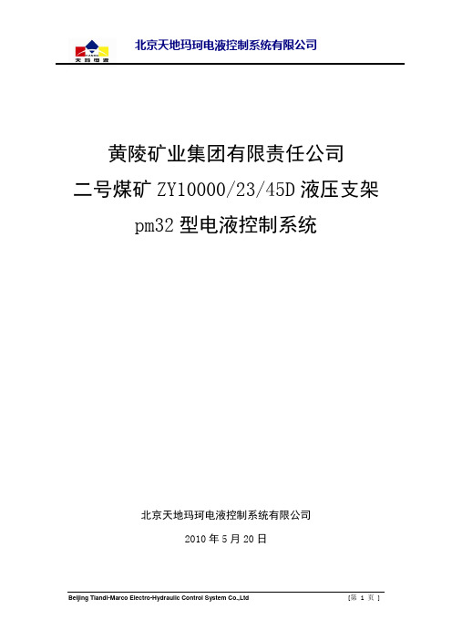
黄陵矿业集团有限责任公司二号煤矿ZY10000/23/45D液压支架pm32型电液控制系统北京天地玛珂电液控制系统有限公司2010年5月20日第一部分工作面及单架pm32电液控制系统备件明细全工作面电控连接原理图基本架、过渡架电控连接原理图端头架电控连接原理图pm32电液控制系统备件清单(黄陵3)序号名称代号数量单位订货号备注1 pm32支架控制器pm32/sg/ag [pm32/sg.] 153 件650000042 控制器安装架(不锈钢/带孔/带后帘板) TMJKH(pm31)D 153 件218000663 控制器接线板组件TMJTP(pm31/sg/cl).00 153 件218010084 内六角螺钉M12X130TMJLDN(M12X130) 306 件218020095 螺母M12 306 件105020636 控制器固定帽套件TMJKF(NL) 306 件218000877 距离管612 件218000048 控制器按键功能指示膜(宁煤6.2米汉显/无胶) pm3/nt:fol.NIMEI6.21N 153 件219010459 电磁阀驱动器mcv/16/7aa [mcv/16] 152 件6500102610 千斤顶行程传感器sns/rs/ai960a [sns/rs/.] 152 根6500301311 行程传感器专用磁环sns/rs/magn.kc 152 件5520100012 行程传感器插座(4sm) TMDDLJ(conm/4sm) 152 件3071100013 圆柱断面U形卡TMKUY(conm4/45) 152 件25521004 行程传感器插座固定14 圆形插座堵头TMDDL(conm4blN) 152 件25521010 行程传感器堵头15 U形卡(47mm) KJ10-DK47 200 件25521011 连接器与行程传感器接插座固定用16 压力传感器sns/dmd/aud0~600bar[sns/dmd.] 158 件6500200617 双路防爆电源箱ntz/d/2xc1.5[ntz/d/2x1.5] 13 件6540000318 隔离耦合器pm3/pa/11/a[pm3/pa/11] 25 件6530400019 耦合器接线板组件TMJTP(pm3/pa/11/a).00 25 件2180100920 隔离耦合器保护罩TMJGH(pm3/pa/11/a) 25 件2180007121 网络终端器pm3/ack/a [pm3/ack] 2 件6530100022 总线提升器pm3/pa/tpu/a[pm3/pa/tpu] 26 件6530000023 圆形插座堵头conm/4bl 1300 件25521006 控制器堵头24 U形卡(42mm) KJ10-DK42 800 件2552101225 U形卡(100mm) TMKUJ(10/4/100) 950 件25521003 控制器长U形卡26 红外线接收传感器pm32/wm/r [pm32/wm.] 150 件6500400027 红外线发射器pm32/wm/b [pm32/wm.] 1 件6500400228 红外线发射器安装架TMJHA(pm32/wm/b) 2 台2180007029 4a型铜头连接器(单头)conm/4a700s 1 根30701096红外线发送器连接器30 电液控换向阀TMFHZY(15)D[FHD500/31.5Z] 152 组30104027 14功能15出口31 U形卡DN10 170 件21509008红外接收器安装架固定用32 井下主控计算机pm3.1/ze/utz/mc 1 件6550003933 软件狗xalz/h/a 1 个6550200034 主控计算机安装架TMJZJA(marco).01 1 件2180008235 信号驱动器conm/adp/cla/a[conm/adp.] 1 件6530200036 电流限位器conm/adp/4lim 2 个6530300037 防爆三通接线盒KBJ-45/1Z 3 件2540400238 电缆接续器TMDDLJ(conm/4ver/at).00 1 个3071200039 4a型铜头连接器conm/4a100 2 根3070101540 4a型铜头连接器(单头) conm/4a100s 2 根3070109241 矿用电缆MHYBV2*2*1.0 400 米15205010 工作面——顺槽主控站连接器42 4a型铜头连接器conm/4a35 26 根30701002 电源箱-耦合器43 4c型护套连接器conmN/4c150 12 根30716006 前压力传感器/驱动器(端头架)44 4c型护套连接器conmN/4c250 25 根30716016 耦合器—本架45 4c型护套连接器conmN/4c300 152 根30716021 红外传感器46 4c型护套连接器conmN/4c350 25 根30716026 耦合器—邻架47 4c型护套连接器conmN/4c200 298 根30716011 行程传感器/驱动器48 4c型护套连接器conmN/4c400 127 根30716031 架间49 4c型护套连接器conmN/4c220 152 根30716013 前压力传感器(端头架)50 4c型护套连接器conmN/4c1500 1 根3071609651 4a型铜头电缆(特殊) conm/4a100(T) 1 根3070109352 接线端子con/uy2 330 个15205017第二部分电控元部件◆pm32支架控制器pm32/sg/ag,订货号:65000004◆控制器接线板组件(不锈钢) TMJTP(pm31/sg/cl).00,订货号:21801008◆电磁线圈驱动器mcv/16//7aa,订货号:65001026◆千斤顶行程传感器sns/rs/ai960a订货号:65003013◆行程传感器专用磁环sns/rs/magn.kc,订货号:55201000◆行程传感器电缆插座TMDDLJ(conm4sm),订货号:30711000 ◆压力传感器sns/dmd/aud 0~600bar,订货号:65002006◆双路防爆电源箱ntz/d/2xc1.5,订货号:65400003◆隔离耦合器pm3/pa/11/a,订货号:65304000◆耦合器接线板组件(不锈钢) TMJTP(pm3/pa/11/a).00,订货号:21801009 ◆隔离耦合器保护罩 TMJGH(pm3/pa/11/a),品号:21800071◆网络终端器 pm3/ack/a,品号:65301000◆总线提升器 pm3/pa/tpu/a,品号:65300000◆圆形插座堵头 conm/4bl,品号:25521006◆圆柱断面U型卡 TMKUY(4.5/43),品号:25521008◆U型卡的(电控) TMKUJ(10/4/100),品号:25521003◆井下主控计算机(含键盘) pm3.1/ze/utz/kc,品号:65500039◆主控计算机安装架 TMJZJA(marco).01,品号:21800082 ◆信号驱动器 conm/adp/cla/a,品号:65302000◆电流限位器 TMDDL(conm/adp/4lim),品号:30712001◆电缆接续器 TMDDLJ(conm/4ver/at).00,品号:30712000◆连接器固定方U型卡型号:KJ10-DK47,订货号:25521011 ◆塑料堵型号:TMDDL(conm4bIN),订货号:25521010◆红外线接收传感器pm32/wm/r,订货号:65004000◆红外线发射传感器pm32/wm/b,订货号:65004002第三部分电液换向阀组备件明细电液控换向阀 TMFHZY(15)D电液控换向阀 TMFHZY(15)D 订货号: 30104027产品备件明细序号订货号代号名称数量单位1 20102032TMFHZY(15)D.00-01 阀体 1 件2 20900029 TMFDCX(0.4/31.5)F[DF1.2/31.5A]电磁先导阀7 件3 20104011 TMFHZY(15)C.01 DN20大阀芯 5 件4 20103017 TMFHZY(15)C.03 DN10差动阀芯 2 件5 20103016 TMFHZY(15)C.02 DN10小阀芯8 件6 20106005 TMFHZY(15)C.04 单向阀 2 件7 20108000 TMFHZY(14).17 过滤器 1 件8 20102034 TMFHZY(15)C.00-02 标牌 1 件9 20102036TMBHZ080606B.00 保护罩 1 件10 20102004TMFHZY(14).00-03 堵2 3 件11 20102005 TMFHZY(14).00-04 堵3 3 件12 20102027TMFHZY(14).00-05 堵5 4 件13 20102037 TMFHZYJ(8).00-03 堵7 16 件14 22103311 GB1235-75 挡圈 3 件15 22100503 EKM O形密封圈 3 件16 22104053 GB1235-75 挡圈 3 件17 22100418 GB/T 3452.1-2005 O形密封圈 4 件18 22100384 EKM O形密封圈16 件19 10508435 GB/T 70.1-2000 内六角螺栓M5×85 28 件20 10501339 GB/T 70.1-2000 内六角螺栓M10×70 3 件21 10800001 ZB-J22-007-88 球涨式堵头DN4 14 件22 10800002 ZB-J22-007-88 球涨式堵头DN5 1 件◆单向阀TMFHZY(15)C.04订货号:20106005序号订货号代号名称数量单位1 22100166 GB3452.1-82 O形圈 1 件2 22100161 GB3452.1-82 O形圈 1 件◆过滤器TMFHZY(14).17 订货号:20108000序号订货号代号名称数量单位1 22100021 GB1235-76 O形圈 1 件2 22100015 GB1235-76 O形圈 1 件◆电磁先导阀TMFDCX(0.4/31.5)F [DF1.2/31.5A] 订货号:20900029产品备件明细序号订货号代号名称数量单位1 20900032 1000.04 电磁铁 1 套2 20900031 1000D.01 先导阀 1 套3 10508435 GB/T 70.1-2000 内六角螺栓M5×854 件4 22100384 EKM O形圈 4 件◆DN20大阀芯TMFHZY(15)C.01订货号: 20104011序号订货号代号名称数量单位1 20104012 TMFHZY(15)C.01-01 进液套 1 套2 20104013 TMFHZY(15)C.01-02 进液阀芯 1 套3 20104004 TMFHZY(14).01-04 弹簧 1 件4 20104005 TMFHZY(14).01-05 阀座 1 件5 20104007 TMFHZY(14)A.01-08 回液阀芯 1 件6 20104014 TMFHZY(15)C.01-06 回液螺套 1 件7 22100331 EKM O形密封圈 1 件8 22104041 EKM 挡圈 1 件9 22100176 EKM O形密封圈 1 件10 22104043 EKM 挡圈 1 件11 22100516 EKM O形密封圈 1 件12 22100462 EKM O形密封圈 1 件13 10508436 GB/T 80-2000 限位螺钉M3×2.5 4 件14 22100333 EKM O形密封圈 1 件15 22100517 EKM O形密封圈 1 件16 22103325 EKM 挡圈 1 件17 22100414 EKM O形密封圈 1 件18 22103326 EKM 挡圈 1 件19 22103332 EKM O形密封圈 1 件20 22104042 EKM 挡圈 1 件DN10小阀芯TMFHZY(15)C.02 订货号: 20103016序号订货号代号名称数量单位1 20103018 TMFHZY(15)C.03-01 进液套 1 套2 20103019 TMFHZY(15)C.03-02 进液阀芯 1 套3 20103005 TMFHZY(14).03-04 弹簧 1 件4 20103006 TMFHZY(14).03-05 阀座 1 件5 20103009 TMFHZY(14)A.03-08 回液阀芯 1 件6 20103020 TMFHZY(15)C.03-06 回液螺套 1 件7 22103194 EKM O形密封圈 1 件8 22104047 EKM 挡圈 1 件9 22103197 EKM O形密封圈 1 件10 22104049 EKM 挡圈 1 件11 22100434 EKM O形密封圈 1 件12 22100483 EKM O形密封圈 1 件13 10508439 GB/T 80-2000 限位螺钉M3×3 4 件14 22100339 EKM O形密封圈 1 件15 22100338 EKM O形密封圈 1 件16 22103327 EKM 挡圈 1 件17 22100337 EKM O形密封圈 1 件18 22103328 EKM 挡圈 1 件19 22103196 EKM O形密封圈 1 件20 22104048 EKM 挡圈 1 件DN10差动阀芯TMFHZY(15)C.03 订货号: 20103017序号订货号代号名称数量单位1 20103018 TMFHZY(15)C.03-01 进液套 1 套2 20103019 TMFHZY(15)C.03-02 进液阀芯 1 套3 20103005 TMFHZY(14).03-04 弹簧 1 件4 20103006 TMFHZY(14).03-05 阀座 1 件5 20103008 TMFHZY(14).03-08回液阀芯 1 件6 20103020 TMFHZY(15)C.03-06 回液螺套 1 件7 22103194 EKM O形密封圈 1 件8 22104047 EKM 挡圈 1 件9 22103197 EKM O形密封圈 1 件10 22104049 EKM 挡圈 1 件11 22100434 EKM O形密封圈 1 件12 22100483 EKM O形密封圈 1 件13 10508436 GB/T 80-2000 限位螺钉M3×2.5 4 件14 22100339 EKM O形密封圈 1 件15 22100338 EKM O形密封圈 1 件16 22103327 EKM 挡圈 1 件17 22100337 EKM O形密封圈 1 件18 22103328 EKM 挡圈 1 件19 22103196 EKM O形密封圈 1 件20 22104048 EKM 挡圈 1 件第四部分高压过滤站1000L自动反冲洗高压过滤站TMGLZD(1000/31.5/25/D/F)订货号:30401011主要组件序号订货号名称规格数量1 21007044 压力表传感器组件TMGLZC1000/31.5/25.03 12 21008069 传感器组件TMGLZD1000/31.5/25.03 13 21008066 阀TMGLZD1000/31.5/25.02F 24 21008070 两色污染指示器TMGLZD1000/31.5/25.06S 15 21008070 接头换向管件TMGLZD1000/31.5/25.07 26 21010007 反冲液回收系统TMGLZD1000/31.5/25.08 17 21005002 滤芯组件TMGLZC1000/31.5/25.05 48 21005007 滤筒组件TMGLZC1000/31.5/25.04 49 21008079 电控器电缆TMGLZD1000/31.5/25.09 110 21007001 主体TMGLZC1000/31.5/25-01 111 21008068 电控控制阀TMGLZD1000/31.5/25.02D 212 21008081 1000电源TMGLZD1000/31.5/25.10 113 21008076 1000支架TMGLZD1000.01 1附属组件订货号名称规格数量21008074 1000标件与其它TMGLZD1000/31.5/25.00B 1 21008067 手动控制体TMGLZS(1000/31.5/25).02.01 1部分组件外观图:两色污染指示器品名:TMGLZD(1000/31.5/25).06s订货号:21008070压力表传感器组件品名:TMGLZC(1000/31.5/25).03订货号:21007004传感器组件品名:TMGLZD(1000/31.5/25).03订货号: 21008069阀品名:TMGLZD(1000/31.5/25).02F订货号:21008066手动控制体品名:TMGLZS(1000/31.5/25).02.01订货号:21005026电动控制阀品名:TMGLZD(1000/31.5/25).02D 订货号:21008068电动控制体品名:TMGLZC(1000/31.5/25).02.01 订货号:21008020滤芯组件品名:TMGLZC(1000/31.5/25).05订货号:21005002。
移动式操作平台备件清单
移动式操作平台备件清单1.电动机和驱动器-电动机:移动式操作平台的电动机通常用于提供动力和驱动平台上的运动。
备件包括电动机本体、电动机连接器、电机风扇、电动机轴承等。
-驱动器:驱动器用于控制电动机的转速和方向,备件包括驱动器主板、驱动器电源模块、驱动器电容器等。
2.控制器和传感器-控制器:移动式操作平台的控制器用于控制平台的运动和操作,备件包括控制器主板、控制器面板、控制器键盘等。
-传感器:传感器用于感知平台的运动和位置,备件包括位移传感器、速度传感器、加速度传感器等。
3.压力和流量控制器-压力控制器:用于控制液压和气动系统的压力,备件包括压力传感器、压力阀等。
-流量控制器:用于控制液压和气动系统的流量,备件包括流量传感器、流量阀等。
4.液压和气动系统的组件-液压系统:备件包括油泵、油箱、液压管路、液压阀等。
-气动系统:备件包括气缸、气动管路、气动阀等。
5.结构和轴系部件-结构部件:备件包括平台框架、支撑柱、安全围栏等。
-轴系部件:备件包括轴承、轴套、轴联轴器等。
6.电气和电子元件-电气元件:备件包括电缆、插头、插座、开关等。
-电子元件:备件包括电子板、保险丝、继电器等。
7.安全装置和紧固件-安全装置:备件包括急停开关、漏电保护器、防爆门等。
-紧固件:备件包括螺丝、螺母、垫圈等。
8.润滑和维护用品-润滑用品:备件包括润滑油、润滑脂、油封等。
-维护用品:备件包括刷子、扳手、擦拭布等。
以上是移动式操作平台常见的备件清单,但不同型号和品牌的操作平台所需的备件有所不同。
企业在购买备件时应根据实际情况选购,同时建立备件库存管理制度,定期检查备件并及时补充,以确保设备的正常运行和延长设备的使用寿命。
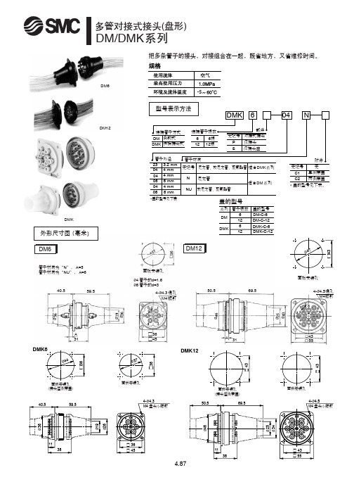
SMC管接头样本
Tube
Union nut
Flared I.D.
Flared I.D. can prevent the tube from deforming inwards. PAT.
Ferrul
Large holding force by metallic style Applicable for use on soft copper steel pipe (Not available for urethane tubing)
3-connection thread
Female Connector: DHF
Applicable Connection tubing O.D. threads
(mm) Rc
Model
H1 H2
(width (width across across
L1
L2
flats) flats)
4
1 4 DHF04-02 17 10 30.3 16
6
14 38
DHF06-02 DHF06-03
17 19
12 30.8 16.5 32.8 18.5
8
1 4 DHF08-02 17 14 29.8 15.5
10
1 4 DHF10-02 17 17 30.8 16.5
12
1 4 DHF12-02 17 19 30.8 16.5
型号选择表
ød
T:R ød
T:R
ød ød
ød
T:R ød
ød
ød ød
T:R
ød
ød
T:Rc
ød
T:Rc
ød
注:尚有铰接型弯头(L系列),铰接型长弯头(LL系列)及堵头(DP系列),可联络SMC营业员。
SMC气缸型号以及附件连接形式
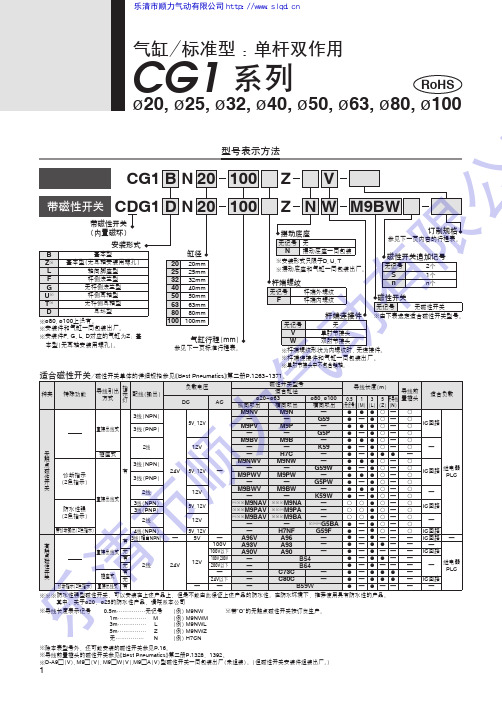
※导线长度表示记号0.5m ……………无记号 (例)M9NW 1m …………… M (例)M9NWM 3m …………… L (例)M9NWL 5m …………… Z (例)M9NWZ 无…………… N (例)H7CN ※带"O"的无触点磁性开关按订货生产。
※除本表型号外,还可能安装的磁性开关参见P.16。
※导线前置插头的磁性开关参见《Best Pneumatics 》第二册P.1328、1392。
※D-A9□(V ), M9□(V ), M9□W (V ),M9□A (V )型磁性开关一同包装出厂(未组装)。
(但磁性开关安装件组装出厂。
)※※※防水性强型磁性开关,可以安装在上述产品上,但是不能由此保证上述产品的防水性。
在防水坏境下,推荐使用具有防水性的产品。
其中,关于ø20、ø25的防水性产品,请联系本公司型号表示方法N N 带磁性开关气缸行程(※※安装件和气缸一同包装出厂。
※安装件F, G, L, D 对应的气缸为Z :基本型(无耳轴安装用螺孔)。
※杆端螺纹形状为内螺纹时,无连接件。
※杆端连接件和气缸一同包装出厂。
※单肘节接头中不包含销轴。
RoHS1气缸/标准型 :单杆双作用ø20, ø25, ø32, ø40, ø50, ø63, ø80, ø100CG1 系列乐清市顺力气动有限公司http://www.slqd.cn乐※对于ø80, ø100,没有基本型(无耳轴安装用螺孔)、杆侧耳轴型、无杆侧耳轴型。
对于ø20~ø63的脚座型、法兰型、耳环型,没有耳轴安装用内螺纹。
使用时,请不要超过允许动能。
详细情况请参考P.4。
缸径(mm )动作方式给油使用流体耐压试验压力最高使用压力最低使用压力环境温度及使用流体温度使用活塞速度行程长度允差缓冲安装形式※单杆双作用不要(不给油)空气1.5MPa1.0MPa 0.05MPa 无磁性开关:−10℃~70℃(未冻结时)带磁性开关:−10℃~60℃~200st mm (ø20)~300st mm (ø25~ø100)垫缓冲0.28J 0.11J0.41J 0.18J0.66J 0.29J1.20J 0.52J2.00J 0.91J3.40J 1.54J5.90J 2.71J9.90J 4.54J +1.40+1.40基本型、基本型(无耳轴安装用螺孔)、轴向脚座型、杆侧法兰型、无杆侧法兰型、杆侧耳轴型、无杆侧耳轴型、耳环型(通口位置作90°变更时使用)※ø80, ø100没有杆侧耳轴型和无杆侧耳轴型。
表面组装元器件SMDSMC
a)电容器结构
b)陶瓷电容器
(2)圆柱形瓷介质电容器
圆柱形瓷介质电容器的主体是一个被覆盖有金 属内表面电极和外表面电极的陶瓷管。为了满足表 面组装工艺的要求,瓷管的直径已从传统管形电容 器的3~6mm减小到1.4~2.2mm,瓷管的内表面电 极从一端引出到外壁,和外表面电极保持一定的距 离,外表面电极引至瓷管的另一端。通过控制瓷管 内、外表面电极重叠部分的多少,来决定电容器的 两个引出端。瓷管的外表面再涂覆一层树脂,在树 脂上打印有关标记,这样就构成了圆柱形瓷介质电 容器。
2.柱形片式电阻器
圆柱形片式电阻器的结构形状和制造方法基本上与带引脚电阻器相 同,只是去掉了原来电阻器的轴向引脚,做成无引脚形式,因而也称为 金属电极无引脚面接合MELF(Metal Electrode Leadless Face)。 MELF主要有碳膜ERD型、高性能金属膜ERO型及跨接用的0W电阻器3 种,它是由传统的插装电阻器改型而来。
云母电容器结构图
5.片式薄膜电容器
随着电子产品趋向小型化、便携式,片式产品的需求量 逐步增大,薄膜电容器的片式化也有较大的发展。片式薄膜 电容器具有电容量大、阻抗低、寄生电感小、损耗低等优点。 它的用范围日趋扩大,无论在军事、宇航等投资类设备中还 是在工业、家电等消费类设备中,已成为不可缺少的重要电 子元件。
多层电感器、线绕电感器、片式变压器等
有源器件
复合器件 分立组件 集成电路
电阻网络、电容网络、滤波器等 二极管、晶体管、晶体振荡器等 片式集成电路、大规模集成电路等
机电器件
开关、继电 器
连接器
微电机
纽子开关、轻触开关、簧片继电器等
片式跨接线、圆柱形跨接线、接插件连接器等 微型微电机等
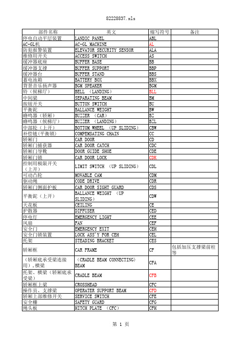
电梯部件名称和缩写
SMC EX260-SPN1 -SPN2 -SPN3 -SPN4 产品配置指南说明书
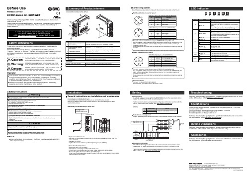
<EX260-SPN1/-SPN2/-SPN3/-SPN4>InstallationConfigurationIn order to configure the SI unit for the PROFINET network, the appropriate device master file (GSD file) for the SI unit will be required.Technical documentation giving detailed configuration information and the GSD file can be found on the SMCwebsite (URL ).General instructions on installation and maintenanceConnect valve manifold to the SI unit.Connectable valve manifolds are the same as for EX250 series SI unit.Refer to the EX250 series valve manifold section in the valve catalogue for valvemanifold dimensions.Power supply connector layoutGround terminalConnect the ground terminal to ground.Resistance to ground should be 100 ohms or less.SettingReplacement of the SI unit•Remove the M3 hexagon screws from the SI unit and release the SI unit from the valve manifold.•Replace the SI unit.•Tighten the screws with the specified tightening torque. (0.6 Nm)Precautions for maintenance •Be sure to switch off the power.•Check there is no foreign matter inside the SI unit.•Check there is no damage and no foreign matter being stuck to the gasket.•Be sure to tighten the screw with the specified torque.If the SI unit is not assembled properly, inside PCBs may be damaged or liquid and/or dust may enter into the unit.Connecting cablesSelect the appropriate cables to mate with the connectors mounted on the SI unit.TroubleshootingTechnical documentation giving detailed troubleshooting information can be found on the SMC website (URL ).SpecificationsConnected load: 24VDC Solenoid valve with surge voltage suppressor of 1.0 W or less (manufactured by SMC)Current consumption of power supply for SI unit operation: 0.1 A max.Ambient temperature for operation: -10 to 50 C Ambient temperature for storage: -20 to 60 CTechnical documentation giving detailed specification information can be found on the SMC website (URL ).Outline DimensionsTechnical documentation giving detailed outline dimensions information can be found on the SMC website (URL ).AccessoriesTechnical documentation giving detailed accessories information can be found on the SMC website (URL ).Assembly and disassembly of the SI unitNOTEWhen conformity to UL is necessary the SI unit must be used with a UL1310Class 2 power supply.Safety InstructionsSafety InstructionsThese safety instructions are intended to prevent hazardous situations and/or equipment damage.These instructions indicate the level of potential hazard with the labels of"Caution", "Warning" or "Danger". They are all important notes for safety and must be followed in addition to International standards (ISO/IEC) and other safety regulations.Operator2 pcs. M3 x 30 screw for connection to the valve manifold Seal cap1 pc. seal cap for unused fieldbus interface connector (BUS OUT)Hexagon socket head cap screw PWR: M12 5-pin plug A-coded (SPEEDCON)GSD fileOutput number assignmentOutput numbering starts at zero and refers to the solenoid position on the manifold.Diagnostic informationWhen the load voltage for the valve is 19 V or less, the SI unit will send an error message to the master as diagnostic information, and the SF LED will turn ON.Technical documentation giving detailed diagnostics information can be found on the SMC website (URL ).Note: Specifications are subject to change without prior notice and any obligation on the part of the manufacturer.© 2011-2016 SMC Corporation All Rights Reserved Akihabara UDX 15F, 4-14-1, Sotokanda, Chiyoda-ku, Tokyo 101-0021, JAPAN Phone: +81 3-5207-8249 Fax: +81 3-5298-5362URL Fieldbus interface connector layoutEX ※※-OMO0031-BThe M12 connector cable has two types, SPEEDCON compatible andnon-compatible. If both plug and socket sides have connectors for SPEEDCON, the cable can be inserted and connected by turning it a 1/2 of a rotation, leading to reduction in work hour.A non-compatible connector can be connected to a compatible connector as well as an M12.The M12 connector cable has two types, SPEEDCON compatible andnon-compatible. If both plug and socket sides have connectors for SPEEDCON, the cable can be inserted and connected by turning it a 1/2 of a rotation, leading to reduction in work hour.A non-compatible connector can be connected to a compatible connector as well as an M12.Before UseFieldbus deviceEX260 Series for PROFINETThank you for purchasing an SMC EX260 Series Fieldbus device (Hereinafter referred to as "SI unit" ).Please read this manual carefully before operating the product and make sure you understand its capabilities and limitations. Please keep this manual handy for future reference.。
MXn烤箱备件手册说明书
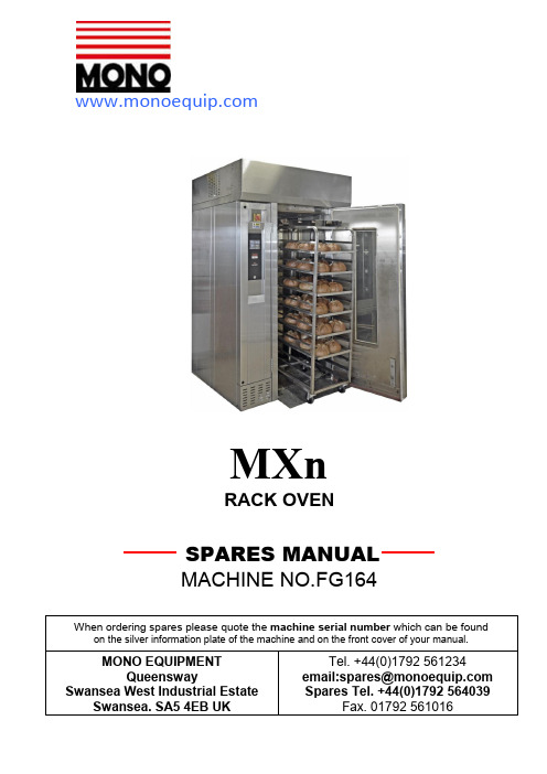
MXn RACK OVENPAGE MAIN COMPONENT PARTS - 3MAIN ELECTRICAL PARTS LIST - 4ELECTRICAL BOX LAYOUT - 5ROOF AREA PARTS LAYOUT - 6REPLACEMENT DAMPER ASSEMBLY - 7WATER INLET COMPONENTS – STANDARD TYPE - 8WATER INLET COMPONENTS – TESCO TYPE - 9MAIN FAN ASSEMBLY PARTS - 10RACK DRIVE ASSEMBLY PARTS -11RACK DRIVE SEAL REPLACEMENT -13ELEMENT BANK FITTING – MAIN COMPONENTS -14ELEMENT CARRIER ASSEMBLY PARTS -15DOOR – MAIN COMPONENTS -16DOOR LOCK COMPONENTS -19REPLACEMENT DOOR LOCK KIT -21MAIN COMPONENTS PARTSMAIN ELECTRICAL – PARTS LISTITEM PART NUMBER DESCRIPTION1 B873-30-015 OVERHEAT THERMOSTAT2 B872-22-074 HEATING ELEMENT MCB3 B872-22-074 HEATING ELEMENT MCB4 B872-22-074 HEATING ELEMENT MCB5 B801-08-032 HEATING ELEMENT CONTACTOR6 B872-07-004 MAIN FAN MOTOR MCB AUXILLARY CONTACTOR7 B872-22-054 MAIN FAN MOTOR MCB8 B872-22-052 TURNTABLE MOTOR MCB9 B872-22-003 INTERIOR LIGHT MCB10 B872-22-062 PUMP MOTOR MCB11 B872-22-061 CONTROL CIRCUIT MCB13A B801-37-001 INTERIOR LIGHT RELAY13B B801-36-001 INTERIOR LIGHT RELAY BASE14 B801-08-031 MAIN FAN MOTOR CONTACTOR15 B801-01-042 MAIN FAN MOTOR THERMAL OVERLOAD16 B801-08-031 TURNTABLE MOTOR CONTACTOR17 B801-01-041 TURNTABLE MOTOR THERMAL OVERLOAD18 B801-93-005 24V DC POWER SUPPLY19 B723-92-002 BUZZER OPTION24 B965-83-004 STEAM SOLENOID25 B998-83-005 DAMPER SOLENOID26 B859-74-024 MAIN FAN MOTOR27 B912-74-009 TURNTABLE MOTOR UNIT28A B801-11-013 TURNTABLE INDEX SWITCH BODY28B B801-45-003 TURNTABLE INDEX SWITCH HEAD28C B801-45-004 TURNTABLE INDEX SWITCH ACTUATOR29 B709-95-001 THERMOCOUPLE30A B801-11-013 DOOR SWITCH BODY30B B801-45-003 DOOR SWITCH HEAD30C B801-45-004 DOOR SWITCH ACTUATOR31A B721-67-011 INTERIOR LIGHT HOLDER31B B857-94-007 INTERIOR LIGHT BULB32A B801-12-022 INTERIOR LIGHT PUSH BUTTON32B B801-14-005 INTERIOR LIGHT PUSHBUTTON CONTACT BLOCK 32C B801-09-011 INTERIOR LIGHT PUSHBUTTON ENCLOSURE32D B801-15-024 INTERIOR LIGHT PUSHBUTTON LEGEND34 158-25-80000 PCB ASSEMBLY35 B979-04-001 HEATING ELEMENT36A B872-22-121 MOULDED CASE CIRCUIT BREAKER36B B872-02-004 UNDERVOLTAGE RELEASE COIL36C B872-19-001 EXTENSION SHAFT AND HANDLE37A B801-37-001 HEATER CONTACTOR RELAY37B B801-36-001 HEATER CONTACTOR RELAY BASE38 B705-25-009 USB CABLE39A B801-37-001 PUMP RELAY (IF PUMP FITTED)39B B801-36-001 PUMP RELAY BASE (IF PUMP FITTED)40 B842-48-010 SUPPRESSOR UNIT (IF PUMP FITTED)41 A900-28-005 WATER PUMP (IF FITTED)42 B842-92-005 SPEAKERELECTRICAL BOX PARTS LAYOUTROOF AREA PARTS LAYOUT2628RACK DRIVE ASSEMBLYDETAILS ON PAGE 11TURNTABLE INDEXFAN MOTORREPLACEMENT DAMPER ASSEMBLYTHE OLD ASSEMBLY WITH SOLENOIDB998-83-005 IS NO LONGER AVAILABLETHIS ASSEMBLY MUST BE SUPPLIED WITHDRAWING 160-38-03000 AS A REPLACEMENTFOR THE OLD DESIGN PARTS.WHEN SUPPLIED AS A SPARE PART, INCLUDE4off FIBRE WASHERS A900-05-190SEE KIT M164-KSE006ITEM PART NUMBER DESCRIPTION QTY160-38-03100 BASE BRACKET 1160-38-03200 SOLENOID BRACKET 1160-38-03300 DAMPER FLAP 1B749-83-004 SOLENOID 1A900-01-197 PIN 1WATER INLET COMPONENTS - STANDARDA900-28-005 GODWIN PUMPRef.G50B0.5HP 240V., 50HZ, 1PHASE, 2850RPM, 2.4AMPSWATER INLET COMPONENTS –TESCO (WITH PUMP)SEE PREVIOUS PAGEFOR DETAILSITEM PART NUMBER DESCRIPTION QTY1 164-01-02400 TUBE 22 A900-05-254 M16 PLAIN WASHER 13 A900-28-005 GODWIN G50B WATER PUMP 14 A900-34-021 15MM COMP. X ¼” BSP MALE COUPLING 15 A900-34-056 3/8” X 3/8” BSPT ST/STEEL NIPPLE 16 A900-34-057 3/8” BSP FEMALE ELBOW 17 A900-34-087 CONNECTING HOSE (1.5Mtr LONG) 18 A900-34-127 Y STRAINER 3/8” BSP 19 A900-34-165 FLOW VALVE 110 A900-34-177 15MM COMP. TO 3/8” MALE 111 A900-34-191 ¼” BSPT MALE TO 3/8” BSPT MALE REDUCER 112 A900-34-203 REDUCING NIPPLE BSPT 1” X ¾” 213 A900-34-218 ¾” X 3/8” REDUCER 114 A900-34-325 CENTRE STRAIGHT COMP. FEMALE IRON 2SOCKET CONNECTOR. 15MM COMP X ¾” FEMALE BRASS15 A900-34-392 WATER PRESSURE REGULATOR 116 B965-83-004 SOLENOID VALVE 1MAIN FAN ASSEMBLY PARTS2456798ITEM PART NUMBER DESCRIPTION QTY1 B859-74-024 MOTOR 12 160-35-00100 MOTOR SLIP PLATE ASSEMBLY 13 160-35-00500 FAN SUPPORT BRAKET 14 160-14-02400 COOLING FAN 15 160-14-10000 DRIVING FLANGE 16 160-14-01700 FAN SHAFT LOWER 17 160-35-01000 LOWER FAN ACCESS COVER 18 160-14-10100 RETAINING WASHER 19 A900-27-049 MAIN FAN 110 160-35-01500 FAN GUARD – SIDE 211 160-35-01600 FAN GUARD – FRONT 112 160-35-01700 FAN GUARD – REAR 1RACK DRIVE ASSEMBLY PARTSITEM PART NUMBER DESCRIPTION QTY1 B912-74-009 GEARMOTOR UNIT (VARVEL MRA70) 22 A900-05-143 M10 PLAIN WASHER 43 A900-05-142 M10 SPRING WASHER 54 A900-03-387 M12 X 45LG HEX HD SETSCREW 45 162-02-04100 DRIVE SHAFT ASSY 16 A900-03-383 M8 X 25LG HEX. HD. SETSCREW 87 A900-05-144 M8 PLAIN WASHER 168 A900-05-141 M8 SPRING WASHER 169 A900-03-439 M8 X 50LG HEX. HD. SETSCREW 810 160-36-01000 TURNTABLE DRIVE (LOWER) 111 A900-03-438 M10 X 45LG HEX. HD. SETSCREW 412 160-15-00600 TOP PLATE 113 160-15-00700 INSULATION PACKING PIECE 414 160-36-00100 BEARING SUPPORT PLATE ASSY 115 162-02-04400 DRIVE SPIDER 116 160-36-00300 TURNTABLE BEARING 117 160-15-00800 TURNTABLE DRIVE (UPPER) 118 160-15-01400 INSULATION DISC 1CONT’DRACK DRIVE ASSEMBLY PARTS Cont’dTO RENEW THE RACK DRIVE SEALThis seal is situated inside the oven above the ring plate surrounding the Rack hanger shaft.1 Release the six dome nuts (A) securing the rack hanger to its shaft andremove the hanger (B). Release the screws securing the ring plate andremove the plate (C).2 Pick out the rubber ring seal and coiled rope seal from within the cavity andcarefully coil in the new seal, ensuring that it is not distorted. Replace therubber ring seal.3 Refit the ring plate and the rack hanger.REPLACEMENT PARTS REQUIRED:ROPE SEAL ……………….. PT No. A900-32-016RUBBER SEAL…………….. PT No. A900-12-060ELEMENT BANK FITTING - MAIN COMPONENTSITEM PART NUMBER DESCRIPTION QTY1 164-31-01300 ELEMENT CARRIER 12 164-07-00800 INSULATION COVER 13164-07-01200 INSULATION COVER 14 164-07-05000 CABLE GUIDE PLATE 15 164-25-00200 MAIN ELECTRIC BOX 16 A900-05-074 FIBRE WASHER 47 164-07-01100 FRONT INSULATION BOARD 18 164-07-01000 REAR INSULATION BOARD 19 164-31-02100 HANDLE 2ELEMENT CARRIER ASSEMBLY PARTSITEM PART NUMBER DESCRIPTION QTY1 164-31-01300 ELEMENT CARRIER WELDMENT 22 160-31-02600 BUSBAR 13 160-31-02800 BUSBAR 14 160-31-02700 BUSBAR 15 160-31-02400 BUSBAR 16 160-31-02500 BUSBAR 17 164-04-07400 BUSBAR 18 160-31-02900 INSULATION BOARD 19 B979-04-001 ELEMENT C/W FASTENERS 1510 A900-03-533 M8 X 35LG HEX HD SCREW 411 A900-04-081 M8 FULL NUT 1012 A900-05-164 M8 SHAKEPROOF WASHER 513 A900-05-012 5/16” WASHER1014 A900-03-361 M6 X 20LG HEX HD BOLT 215 A900-04-080 M6 FULL NUT 2 16A900-05-140 M6 WASHER 2 17A900-05-163 M6 SHAKPROOF WASHER 2 18164-31-02100 DETACHABLE HANDLE 2DOOR – COMPONENTS91078621 354620421 123213 263 ”SECTION “B”-“B”SECTION “A”-DOOR – LOCK COMPONENTSLEVERHANDLE CONNECTING RODTENSION PIN KEEPER PLATESLIDE PIN6 20SLIDE PIN DENOTES FIXING. SEE PARTS LIST FOR DESCRIPTION”DOOR –LOCK COMPONENTS Cont’dITEM PART NUMBER DESCRIPTION QTY1 160-32-02000 HANDLE 12 *160-48-01400 LEVER 13 160-48-01600 CONNECTING ROD 14 160-48-01700 KEEPER PLATE 15 160-48-01800 PEDAL 16 160-48-01900 SLIDE PIN 27 160-48-02000 EXIT LABEL 18 160-48-02100 BALANCE WEIGHT 19 *160-48-10900 HANDLE LINK 1 10*160-48-11000 LOCK HOUSING BASE 1 11*160-48-10000 LOCK HOUSING COVER 112 A900-27-072 BOLT AND GUIDE 213 A900-03-714 M6 X 16LG CSK/SKT HD ST ST SCREW 614 A900-03-374 M8 X 12LG HEX HD ST ST SCREW 115 A900-05-141 M8 SPRING WASHER 116A900-03-532 M8 X 20LG HEX HD SCREW 2 17A900-05-164 M8 LOCK WASHER 2 18A900-03-372 M4 X 12LG HEX HD SCREW 419 A900-05-162 M4 LOCK WASHER 420 A900-05-143 M10 PLAIN WASHER 421 A900-01-120 3MM DIA. TENSION PIN X 15MMLG 322 A900-03-360 M6 X 12LG HEX HD SCREW 2223 SUPPLIED WITH HANDLE M8 X 40LG CSK/HD/PLATED SCREW 124 A900-05-163 M6 SHAKEPROOF WASHER 20 25*A900-27-121 LINK 226 A900-02-897 M6 X 12LG CSK/SKT HD ST ST SCREW 8*See next page for views of replacement lock kit containing these items.MX OVEN - REPLACEMENT DOOR LOCK KITLH DOOR LOCK KIT M160-KSX005RH DOOR LOCK KIT M160-KSX004ASSEMBLED10160-48-11001= LH160-48-10900= RHNOTEThis can also be used to replace the older Sampson aluminium lock housing foundon very early mx ovens.21FG164 MX RACK OVEN SPARES REV.A16 09/06/16。
行业英语

Manufacturing department 制造部一、assembly line 装配线1.产品产品product / production半成品semi-manufactured goods / semifinished goods /semifinished product / semifinished articles成品finished goods / finished product / finished stock / finished articles 最终产品final goods装配件,组装件assembly parts副产品byproduct副产物coproduct加工,制造manufacture v.& n.生产produce v.Production n.装配assemble v.Assembly n.试产,试制v. trial-produce / trial-manufacture试产,试制n. control run / pilot run / pilot production批量生产mass production / batch production / repetitive manufacturing 车间workshop / shop floor流水车间flow shop加工车间job shop车间管理shop management产线line生产线production line装配线,组装线assembly line部件装配线subassembly line工作,作业员worker产线作业员operator直接人工direct labor DL间接人工indirect labor IDL设备equipment设备,装置device机器machine工具tool治具fixture器械apparatus仪器instrument输送带conveyer belt /conveyor belt轮班shift白班,日班day shift晚班,夜班night shift换班工作shift work产能production capacity / production capability制造能力manufacturing capacity /manufacturing capability生产力productivity生产量throughput投入数input quantity产出数output quantity良率yield直通率,一次良率first pass yield FPY二次良率second pass yield直通率rolled yield累计直通率rolled throughput yield RTV不良率defect rate / failure rate / NG rate废品率defective index百分比percentage / percent / per cent工作指导书working instruction WI操作说明书operation instruction OI首件检查报告first article inspection report FAIR / first piece inspection report FPIR 测试项目test item检测方法test mode测试程式test program工单,工令work order制令manufacture order生产记录production record点检表check list检修troubleshooting检修员trouble shooter修理repair替换replace报废scrap调试,检测并排除故障debug拆卸,分解v. disassemblen. disassembly废料槽,废品盒reject box维修件service parts备用零件repair parts修理用工具箱repair box备品spare parts备品仓库spare parts store / repair parts stock螺丝起子screwdriver钳子forceps刀子knife电动起子automatic screwdriver冷却液coolant酒精alcohol油脂grease润滑油lubricating oil润滑剂lubricant脱模剂release agent机种model逐步淘汰phase out逐步采用phase in停工,停产shut down停电power cut / power failure / power blackout 站别,工位station备用工位backup station制程process生产流程production flow / production procedure 流程图flow chart制造流程图manufacturing flow chart品管流程图QC flow chart制程管理计划process management plan PMP 工艺流程图process flow chart PFCProcess flow diagram PFD二,PLASTIC MALDING 塑胶成型模具tooling模mold穴cavity模号mold No.穴号cavity No. / cav. No.硬模die模仁core公模male mold母模female mold简易模plain die成型模inner molding成型外模over molding塑胶plastic可塑化plasticization射出成型injection molding押出成型extrusion molding注射机injection molding machine射出injection射出率injection rate射出压力injection pressure料斗容量material hopper capacity冷却液coolant冷却固化cooling and solidification冷却水路cooling channel浇口gate主流道primary runner次流道sub-runner充填filling保压packing压缩compression置压holding冷却cooling后填充post-filling熔合线weld line分模线parting line P/L合模mold clamping开模mold opening合模力,锁模力clamping force开模力opening force顶出ejection脱模剂release agent毛边flash缩水shrinkage翘曲warpage破裂cracking缺口nick溢料flash突起bump气泡bubble刮伤scratch烧焦burn拖痕drag mark流痕flow mark冷料cold slug微粒particles分层delamination光泽不良haze导色blush变色discoloration(表面)油脂grease污物contamination三、METAL STAMPING 金属冲压冲压stamping冲压部stamping department冲孔,打孔v./ 冲压机,冲床n. punch 冲外形punch external form凸摸强度punch strength冲杆冲程punch advance凸摸行程punch travel凸摸破坏punch failure(冲剪)边角料punched scrap冲模,硬模die四、PROCESS OF SMT SMT制程表面安装技术surface mount technology SMT 表面安装元件surface mount device SMD表面安装元器件surface mount component SMC 助焊剂flux焊接液soldering fluid焊锡丝solder wire焊锡条solder bar焊锡膏solder paste表面贴片胶surface mount adhesives SMA锡膏印刷机paste printer高速机,贴片机high-speed mounter焊锡炉soldering furnace波峰焊设备wave soldering machine在线测试仪In-circuit Tester ICT自动光学检验automatic optical inspection AOI 送料器feeder喷嘴,吸嘴nozzle放大镜magnifier显微镜microscope显示器monitor液晶屏幕LCD screen焊工solderer烙铁soldering iron焊接,焊料solder焊接温度soldering temperature可焊性solderability焊接不良poor soldering开路open短路short锡桥solder bridge空焊void solder虚焊false solder冷焊cold solder污染物contaminant异物foreign materials杂质foreign matter手环wrist strap静电手环ESD strap静电帽antistatic cap静电手套antistatic gloves静电衣antistatic coat静电鞋antistatic slipper防静电容器antistatic container离子风扇ionic fan无铅制程Pb-free process / lead-free process五、PACKING 包装包装v.&n. packing包装n. packaging包装规范packing specification内包装inner packaging外包装outer packaging包装材料wrapper包装纸wrapping paper包装工人,打包机packer散装bulk pack散装地in bulk瓶装的bottled罐装的canned桶装的barreled密封包装sealed package真空包装vacuum packing可堆叠的stackable装运货物的箱子packing case硬纸箱carton托盘tray袋子bag箱子,盒子box / case礼品盒,彩盒gift box管子tube卷盘,卷轴reel / roll隔板clapboard纸板cardboard干燥剂desiccant盖子cover密封盒sealed case密封帽sealed cap密封盖sealing cover软垫,衬垫cushion海绵spinge保利龙,泡沫塑料polyfoam气泡袋air bubble bag带子tape封箱胶带adhesive tape封条sealing tape包装机packing machine产品标准号product standard code条形码bar code条形码标签bar code labelQUALITY ASSURANCE DEPARTMENT 品保部质量,品质quality高品质,高质量high quality质量检查quanlity inspection质量评价quality review质量评审quality review质量指标quality index / quality target品质稽核quality audit品检员quality inspector质量方针quality policy质量目标quality objectives质量手册quality manual程序procedure质量文件quality document记录record原材料raw material标准件standard parts检验区inspection area进料检验incoming inspection / receiving inspection 收料单receipt收货单receiving note检验规范incoming inspection index工程图纸engineering drawing检验记录recording sheet标准检验程序standard inspection procedure标准操作程序standard operating procedure图纸drawing零件图。
倍速输送链条组装线简析
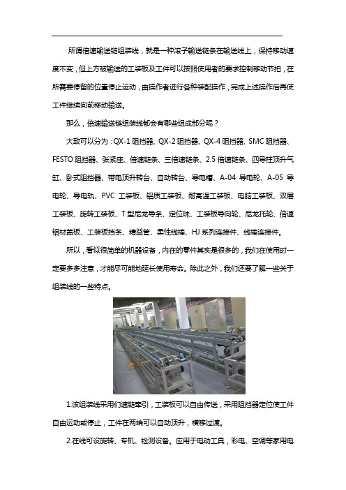
所谓倍速输送链组装线,就是一种滚子输送链条在输送线上,保持移动速度不变,但上方被输送的工装板及工件可以按照使用者的要求控制移动节拍,在所需要停留的位置停止运动,由操作者进行各种装配操作,完成上述操作后再使工件继续向前移动输送。
那么,倍速输送链组装线都会有哪些组成部分呢?大致可以分为:QX-1阻挡器、QX-2阻挡器、QX-4阻挡器、SMC阻挡器、FESTO阻挡器、张紧座、倍速链条、三倍速链条、2.5倍速链条、四导柱顶升气缸、卧式阻挡器、带电顶升转台、自动转台、导电槽、A-04导电轮、A-05导电轮、导电轨、PVC工装板、铝质工装板、耐高温工装板、电脑工装板、双层工装板、旋转工装板、T型尼龙导条、定位珠、工装板导向轮、尼龙托轮、倍速铝材盖板、工装板挡条、精益管、柔性线棒、HJ系列连接件、线棒连接件。
所以,看似很简单的机器设备,内在的零件其实是很多的,我们在使用时一定要多多注意,才能尽可能地延长使用寿命。
除此之外,我们还要了解一些关于组装线的一些特点。
1.该组装线采用们速链牵引,工装板可以自由传送,采用阻挡器定位使工件自由运动或停止,工件在两端可以自动顶升,横移过渡。
2.在线可设旋转、专机、检测设备。
应用于电动工具,彩电、空调等家用电器、各类仪器仪表及机电产品等总装及部装。
3.采用柔性倍速链为输送介质,工装板为载体,带动工件以2.5倍、3倍链条传送的速度动行,常用于家电产品,摩托车发动机、汽车配件、电动工具等的装配与检测。
4.工位可设置气动阻挡器、脚踏开关、线内顶升旋转、顶升移动以及各种装配、检测设备,工装板上也可根据产品的生产工艺配置各种工装夹具,实现产品的自动化生产。
5.输送方式由单排链式、三排链式并可随意组合。
以上就是组装线的大致介绍,希望能对想要购置的人有所帮助。
杭州傲州链传动有限公司具有先进的制造技术与较强制造力,精密的检测仪器,确保出厂的每一根链条都质量合格。
公司主要生产产品有各种A,B系列传动用短节距精密滚子链,双节距传动链和输送链,短节距输送滚子链附件,双节距输送滚子附件,立体车库链,空心销轴滚子链和套筒链条,大滚子输送链及附件,ZGS38联合收割机链及附件输送链,质量稳定,产品经久耐用。
SMC公司产品说明书
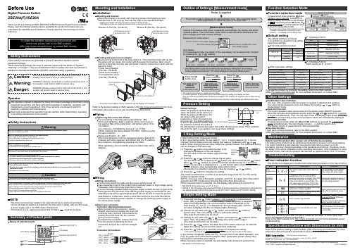
Other SettingsSummary of Product partsSimple Setting ModeTroubleshootingNote: Specifications are subject to change without prior notice and any obligation on the part of the manufacturer.© 2017 SMC Corporation All Rights ReservedAkihabara UDX 15F, 4-14-1, Sotokanda, Chiyoda-ku, Tokyo 101-0021, JAPANPhone: +81 3-5207-8249 Fax: +81 3-5298-5362URL Specifications/Outline with Dimensions (in mm)Refer to the product catalog or SMC website (URL ) for moreinformation about the product specifications and outline dimensions.PS※※-OMU0001 InstallationMounting with bracketMount the bracket to the body with mounting screws (Self tapping screws:Nominal size 3 x 8L (2 pcs)), then set the body to the specified position.∗: Tighten the bracket mounting screws to a torque of 0.5±0.05 Nm.Self tapping screws are used, and should not be re-used several times.∗: The panel mount adapter can be rotated through 90 degrees for mounting.•Bracket A (Part No.: ZS-46-A1)•Bracket B (Part No.: ZS-46-A2)Mounting with panel mount adapterMount part (a) to the front of the body and fix it. Then insert the body with (a) intothe panel until (a) comes into contact with the panel front surface. Next, mountpart (b) to the body from the rear and insert it until (b) comes into contact with thepanel for fixing.WiringWiring connectionsConnections should be made with the power supply turned off.Use a separate route for the product wiring and any power or high voltage wiring.Otherwise, malfunction may result due to noise.If a commercially available switching power supply is used, be sure to ground theframe ground (FG) terminal. If the switching power supply is connected for use,switching noise will be superimposed and it will not be able to meet the productspecifications. In that case, insert a noise filter such as a line noise filter/ferritebetween the switching power supplies or change the switching power supply tothe series power supply.How to use connectorConnector attachment/detachmentWhen connecting the connector, insert itstraight onto the pins, holding the lever andconnector body, and lock the connector bypushing the lever hook into the concavegroove on the housing.To detach the connector, remove the hookfrom the groove by pressing the leverdownward, and pull the connector straightout.DC(+)Pin No.OUT1OUT2FUNCDC(-)BrownBlackWhiteGrayBluePipingTightening the connection threadFor connecting to the body (piping specification: -M5)After hand tightening, apply a spanner of the correct size tothe spanner flats of the piping body, and tighten with a 1/6 to1/4 rotation.As a reference, the tightening torque is 1 to 1.5 Nm.(When replacing the piping adapter ZS-46-N∗, tighten it usingthe same method.)Piping specification: -01, -N01After hand tightening, hold the hexagonal spanner flats of thepressure port with a spanner, and tighten with 2 to 3 rotations.As a reference, the tightening torque is 3 to 5 Nm.When tightening, do not hold the pressure switch body with aspanner.Default settingsWhen the pressure exceeds the setvalue, the switch will be turned on.When the pressure falls below theset value by the amount ofhysteresis or more, the switch willbe turned off. The default setting isto turn on the pressure switch whenthe pressure reaches the centre ofthe atmospheric pressure and upper limit of the rated pressure range. If this condition,shown to the right, is acceptable, then keep these settings.Error indication functionThis function is to display error location and content when a problem or error has occurred.above are displayed, please contact SMC.Refer to the SMC website (URL ) for more information abouttroubleshooting.Power is supplied.button between1 and 3 sec.∗:The outputs will continue to operate during setting.∗:If a button operation is not performed for 3 seconds during the setting, the display will flash.(This is to prevent the setting from remaining incomplete if, for instance, an operator were to leave duringsetting.)∗:3 step setting mode, simple setting mode and function selection mode settings are reflected each other.[3 step setting mode (hysteresis mode)]orcan be changed in the same way.button once when the item to beThe set value on the sub display (right) will startflashing.orbutton.buttons are pressed and held simultaneously for 1 second orlonger, the set value is displayed as [- - -], and the set value will be the same as thecurrent pressure value automatically (snap shot function).Afterwards, it is possible to adjust the value by pressing button.button to complete the setting.The pressure switch turns on within a set pressure range (from P1L to P1H) duringwindow comparator mode.Set P1L, the lower limit of the switch operation, and P1H, the upper limit of the switchoperation and WH1 (hysteresis) following the instructions given above.(When reversed output is selected, the sub display (left) shows [n1L] and [n1H].)∗:Set OUT2 in the same way. (ex. P_2, H_2)∗:Setting of the normal/reverse output switching and hysteresis/window comparator mode switchingare performed with the function selection mode [F 1] OUT1 setting and [F 2] OUT2 setting.value[F 0] Units selection functionPeak/bottom value indicationbutton inmeasurement mode.Snap shot functionbuttons for 1 secondor longer simultaneously. Then, the set value of the sub display (right) shows [- - -], andthe values corresponding to the current pressure values are automatically displayed.Zero-clear functionbuttons are pressed for 1 second orlonger simultaneously, the main display shows [- - -], and the reset to zero.The display returns to measurement mode automatically.Key-lock functionTo set each of these functions, refer to the SMC website(URL ) for more detailed information, or contact SMC.button between 1 and 3 seconds in measurementmode. [SEt] is displayed on the main display. When the button is releasedwhile in the [SEt] display, the current pressure value is displayed on themain display, [P_1] or [n_1] is displayed on the sub display (left), and theset value is displayed on the sub display (right) (Flashing).or button to(The snap shot function can be used.)or button to set the(The snap shot function can be used.)or button, the delay time of the switch output can be selected.button for 2 seconds or longer to complete the setting.∗:If the button is pressed for less than 2 seconds, the setting will moves to the OUT2 setting.In the window comparator mode, set P1L, the lower limit of the switch operation, andP1H, the upper limit of the switch operation, WH1 (hysteresis) and dt1 (delay time)following the instructions given above.(When reversed output is selected, the sub display (left) shows [n1L] and [n1H].)∗:Set OUT2 in the same way.Function selection modebuttonbetween 3 and 5 seconds, to display [F 0].Select to display the function to be changed[F button for 2seconds or longer in function selection modeto return to measurement mode.∗:Some products do not have all the functions. If no functionis available or selected due to configuration of otherfunctions, [- - -] is displayed on the sub display (right).Names of individual partsRefer to the product catalog or SMC website (URL ) for moreinformation about panel cut-out and mounting hole dimensions.Pressure Setting3 Step Setting Mode(URL ) for more detailed information, or contact SMC.MaintenanceHow to reset the product after a power cut or forcible de-energizingThe setting of the product will be retained as it was before a power cut or de-energizing.The output condition is also basically recovered to that before a power cut or de-energizing, but may change depending on the operating environment. Therefore, checkthe safety of the whole installation before operating the product. If the installation is usingaccurate control, wait until the product has warmed up (approximately 10 to 15 minutes). Safety InstructionsBefore UseDigital Pressure SwitchZSE20A(F)/ISE20AThank you for purchasing an SMC ZSE20A(F)/ISE20A Series Digital Pressure Switch.Please read this manual carefully before operating the product and make sure youunderstand its capabilities and limitations. Please keep this manual handy for futurereference.Safety InstructionsThese safety instructions are intended to prevent hazardous situations and/orequipment damage.These instructions indicate the level of potential hazard with the labels of "Caution","Warning" or "Danger". They are all important notes for safety and must be followed inaddition to International standards (ISO/IEC) and other safety regulations.OperatorSwitch ONAt normal output Switch OFFSet valueP_1HysteresisH_1TimePressureDefault settingThe default setting is as follows.If no problem is caused by this setting,keep these settings.Connector pin numbers[F 2] Setting of OUT2Same setting as [F 1] OUT1.NOTE•The direct current power supply to be used should be UL approved as follows:Circuit (of Class 2) which is of maximum 30 Vrms (42.4 V peak), with UL1310 Class2 power supply unit or UL1585 Class 2 transformer.•The product is a UL approved product only if it has a mark on the body.。
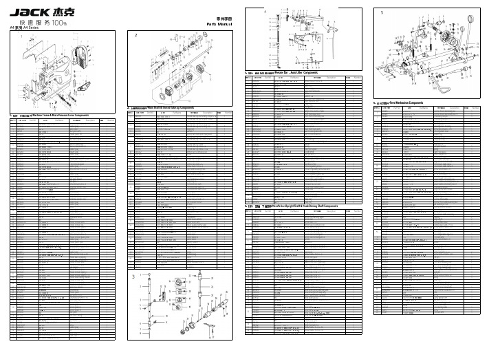
A4 系列压料、自动抬压脚分组件说明书
5零件手册Parts ManualA4 系列 A4 Series14. 压料、自动抬压脚分组件/Presser Presser Bar Bar ,Auto Auto Lifter Lifter Components公司件号 Part NO.名称 PartName零件描述 Description压脚扳手螺钉SM9/64"x40 L=11Screw SM9/64"x40 L=11压脚扳手螺钉垫圈Washer 压脚扳手Hand lifter O 型圈Rubber ring 压脚扳手凸轮分部件Hand lifter cam asm.前杠杆螺纹销Screw 螺纹销橡胶垫圈(厚)Washer (H )抬压脚前杠杆分部件Lift front lever component 抬压脚拉杆Knee lifter pull rod 5. 送料分组件/Feed Feed Mechanism Mechanism ComponentsGB/T896-1986挡圈 5Snap ring Main Shaft & Thread Take-up Components压脚升降板Lifting plate序号NO.公司件号 Part NO.名称 PartName零件描述 Description数量 Number抬压脚拉杆螺钉SM3/16"x32Hinge Screw SM3/16"x32Part NO.名称 PartName零件描述 Description后杠杆轴位螺钉SM15/64"x28Hinge screw SM15/64"x28111405015倒送料连杆Reverse feed connecting rod 11. 机壳、外装分组件/Machine Frame & Miscellaneous Cover Components抬压脚后杠杆Knee lifter back lever 11305015倒送料连杆(-7)Reverse feed connecting rod(-7)1挑线连杆销 (厚料)Thread take-up connecting rod pin (抬压脚顶杆Knee lifter connecting rod 211426021倒送料连杆销Connecting rod pin 1公司件号 Part NO.名称 PartName零件描述 Description挑线连杆销Thread take-up connecting rod pin 松线导管上支架Wire release bracket upper 11326011倒送料连杆销(-7)Connecting rod pin(-7)1上轮螺钉 SM15/64"x28 L=15Screw SM15/64"x28 L=15松线导管压板Wire release press plate 3101S11005螺钉 SM9/64"x40 L=6Screw SM9/64"x40 L=66101S11001后窗板螺钉SM3/16"×28 L=9Screw SM3/16"×28 L=9挑线连杆(厚料)Thread take-up connecting rod (H)油管压板螺钉SM3/16"x28 L=7Screw SM3/16"x28 L=7410101053送料调节器Feed regulator 110122003面板调节孔螺塞Rubber plug 挑线连杆Thread take-up connecting rod 松线导管压板螺钉M4x8Screw M4x8511403043送料调节器轴套Feed regulator bushing 113837002商标牌Head card GB/T896-1986挡圈Snap ring 抬压脚前杠杆组件Knee lifter lever asm 6101S11023送料调节器轴端螺钉SM3/16"x28 L=6.5Screw SM3/16"x28 L=6.51302591面板(喷漆)Face plate asm 垫片washer713826005标盘螺柱Feed regulator stud 113813005左线钩Thread guide left 针杆曲柄护板Needle bar crank protecting plate 810122016送料调节螺钉O形圈Rubber ring 1101S11007右线钩螺钉SM11/64"×40 L=6Screw SM11/64"×40 L=6挑线杆分组件Thread take-up lever asm.913811008固定表盘Fixing dial plate 113822006面板垫Face plate gasket 挑线杆组件(厚料)Thread take-up lever asm.(H )13811008固定表盘(-7)Fixing dial plate(-7)1101S11027防油板螺钉SM1/8"×44 L=3.4Screw SM1/8"×44 L=3.4挑线杆滚针轴承Needle bearing 13811013固定表盘(H-M )Fixing dial plate(H-M)110412007面部防油板Face oil shield asm.挑线曲柄分部件Thread take-up crank 10H05018GB/T896-1986挡圈3.5Snap ring 3.5111412082面部防油板(厚料)Face oil shield asm.(H)挑线曲柄分部件(厚料)Thread take-up crank (H )1113811009标盘按钮Dial plate button 110122013针杆上衬套孔塞Rubber plug 挑线曲柄分部件(H-M )Thread take-up crank (H-M )1213827002按钮复位簧Spring110122005挑线连杆销螺孔塞Rubber plug 针杆连杆Needle bar connecting rod 1313812010上限位片Upper limit patch 110122004针杆曲柄螺孔塞Rubber plug挑线曲柄螺钉(左旋)Screw141381100700标盘旋钮组件Knob component 1101S11004挑线杆护罩螺钉SM3/16"×28 L=7Screw SM3/16"×28 L=7针杆曲柄紧固螺钉 SM9/32"x28 L=16Screw SM9/32"x28 L=1615101S11022送料距旋钮螺钉SM3/16"x28 L=18Screw SM3/16"x28 L=181********挑线杆防护罩Thread take-up lever cover 针杆曲柄定位螺钉SM9/32"x28 L=16Screw SM9/32"x28 L=16101S11004挑线杆护罩螺钉SM3/16"×28 L=7Screw SM3/16"×28 L=7针杆曲柄Needle bar crank 13512004三孔线勾3-hole thread guide 针杆曲柄(厚料)Needle bar crank (H )10122005挑线连杆销螺孔塞Rubber plug送料轴挡圈螺钉SM1/4"x40 L=6Screw SM1/4"x40 L=6114S11015割线刀螺钉SM9/64"×40 L=6Screw SM9/64"×40 L=6上轴前轴套组件Main shaft bushing front 11419001割线刀Knife 夹线器螺钉SM15/64"x28 L=7Screw SM15/64"x28 L=720722002油塞Rubber plug 主轴中轴套Main shaft bushing mid 13822001操作屏孔塞Rubber plug 上轴中套挡圈螺钉Screw13822007后窗板垫Side plate gasket 上轴挡圈Main shaft thrust collar 302592后窗板(喷漆)Side plate挡圈20Snap ring 20101S11001后窗板螺钉SM3/16"×28 L=9Screw SM3/16"×28 L=9送料偏心轮 Feed eccentric cam 13811031一体机电控罩壳(鲍麦克斯)Electronic control box 送料偏心轮(厚料)Feed eccentric cam (H)W01009GB/T97.1-1985垫圈 5Washer 5送料偏心轮(H-M)Feed eccentric cam (H-M)114S13001直驱电机螺钉M5×20Screw M5×20送料偏心轮盖板Cover plate 114S30001螺栓(内六角)M5×25Screw M5×25送料偏心轮盖板(H-M)Cover plate(H-M)13833010一体机电控组件(琦星)Electronic control box(Q)送料偏心轮螺钉 SM1/4"x40 L=13Screw SM1/4"x40 L=1313833013一体机电控组件(鲍麦克斯)Electronic control box 护针片螺钉 SM9/64"x40 L=5Screw SM9/64"x40 L=510122006送料调节器孔塞Rubber plug 上轴后轴套The rear axle sleeve 10122007下轴工艺孔塞Rubber plug 上轴后套挡油油封Oil seal 138S05001操作面板螺钉ScrewGB/T894.1-1986挡圈15Snap ring 1513833012一体机电控面板组件(琦星)Control panel(Q)上轴Main shaft 13833015一体机电控面板组件(鲍麦克斯)Control panel 手轮贴条Handwheel lable 101S12001底板支柱Machine head stud 螺钉Screw 13822002装饰条Decorative article 手轮(喷漆)Handwheel 101S11004螺钉Screw电机罩壳组件(配琦星)Motor cover asm(Q)1381300400小夹线器组件Thread tension asm.电机罩壳组件(配鲍麦克斯)Motor cover asm138S16019小夹线器螺母Thread tension nut 电机光栅组件(配鲍麦)Motor grating sensor asm 11227001小夹线弹簧Thread tension spring6`12. 机头附件(1)-线架组件/Machine Head Accessories(1)-Thread Stand Components公司件号 Part NO.名称 PartName零件描述 Description8. 润滑、油量检测组件/Oil Oil Lublication 、Oil Oil Measuring Measuring Components20131019线架杆顶防护橡皮Spool rest rod rubber cap 公司件号 Part NO.名称 PartName零件描述 Description数量 S04050 十字槽凹穴六角头螺栓 M5 L=16 Screw M5 L=16 W01047垫圈M5Washer M5油窗Oil sight window N01034 螺母 M5Nut M510122019油窗O形圈Rubber ring 13831022上线架过线杆 Spool rest arm upper 上轴供油管Main shaft oil tube 10113011过线圈(内)Thread guide ring 112S30005油泵连接螺柱Oil pump connecting stud 10113010过线圈(外) Thread guide ring 11329010开口挡圈10Snap ring 1013831019线架杆上节Spool rest rod upper 6. 切线装置部件/Thread Trimmer Components供油管Hook oil tube13831021线架杆接头 Spool rest rod joint 10112020油泵安装板Oil pump installing base 13831020线架杆下节Spool rest rod lower 序号NO.公司件号 Part NO.名称 PartName零件描述 Description数量 NumberW03002弹垫Spring washer10122106橡胶垫圈Spool rest rod rubber ring 209S12001压脚螺钉SM11/64"×40 L=10.5Screw SM11/64"×40 L=10.5W01048垫圈M16Washer M161113S15002定刀调节螺钉SM1/8"x44 L=9.5Screw SM1/8"x44 L=9.5110103022油泵体衬套Oil pump bushing N02008六角薄螺母 M16Spool rest rod nut M16211319001定刀Secant knife 1101S30007柱塞螺钉Plunger Screw 10. 绕线器组件/ Bobbin ComponentsS04051十字槽凹穴六角头螺栓 M5Spool rest arm lower screw M53113S17001螺钉SM9/64"x40Screw SM9/64"x40110127013柱塞簧Plunger spring N01034 螺母 M5Nut M5411312003护针片Needle guard patch 110122018回油柱塞Plunger 公司件号 Part NO.名称 PartName零件描述 Description数量 W03002弹簧垫圈 5Spring washer 55201S11009螺钉SM9/64"x40 L=5.5Screw SM9/64"x40 L=5.5110120001油泵体Oil pump 6113S11001螺钉SM11/64"x40 L=12Screw SM11/64"x40 L=122油泵螺钉Screw1383103900绕线器组件Bobbin winder asm.油泵叶轮Oil pump impeller 114S11008螺钉M4x6Screw M4x6油泵叶轮托板Oil pump impeller cover GB/T97.1 垫圈4Washer油泵盖Lubricating oil pump cover 10113030压线控制板Thread press control plate 101S30006螺钉Screw10111120绕线衬垫Winding pad 1012000100油泵分部件Lubricating oil pump component 13831101绕线器装置主座Bobbin winder bed116S30003抬牙叉固定螺钉SM15/64"×28 L=14.5Screw SM15/64"×28 L=14.5GB/T 896-1986 开口挡圈5Snap ring 10136001供油管接头Rubber joint 10127061复位板拉簧Spring13812110调节板Regulating plate 10110030绕线凸轮Bobbin winder cam S09045螺钉Screw1380510600绕线器连杆组件Bobbin winder connecting rod 13827103满线复位簧spring 10127060弹簧Spring GB/T 896-1986开口挡圈4Snap ring13802111绕线器主轴Bobbin winder mian shaft 13802026绕线凸轮轴Bobbin winder cam shaft S09103绕线轮螺钉Screw13831102绕线轮Bobbin winder wheel O01110O 型圈Ring 11422062密封垫Washer114S11003螺钉SM3/16"×28 L=10Screw SM3/16"×28 L=101381300600底线夹线器Bobbin thread tension asm.13811004夹线螺母Thread tension nut 11427006小夹线弹簧Spring10112005夹线板Thread tension disk 11413022夹线过线板Thread tension guide plate 112S13004夹线螺钉Screw114S16001螺母SM11/64"×40Nut SM11/64"×4012. 机头附件(2)/Machine Head Accessories(2)公司件号 Part NO.名称 PartName零件描述 Description数量 1011203100机头连接钩部件 Hinge component10122060机头连接钩座 Head connecting rubber cushion 10117021机针(14#)Needle (14#)10117022机针DP×5#21(厚料)Needle (H)101S30010 机头连接钩座钉 Nail 10118003梭心 Bobbin机头支柱 Machine head rest pin 20731047螺丝刀(大)Screw driver10131003螺丝刀(中) Screw driver,medium9. 自动倒送料开关、感应抬压脚组件/Automatic Automatic Reverse Reverse Feed Feed ComponentsNO.公司件号 Part NO.名称 PartName零件描述 Description数量 NumberS05254GB/T70.1-2000螺钉M2.5×4Screw M2.5×411383004600下感应探头Lower sensor1201S11012螺钉SM9/64"×40 L=7.7Screw SM9/64"×40 L=7.7113813022过线压板Screw M4x8113822030橡皮塞(单孔)Rubber plug1101S11004挑线杆护罩螺钉SM3/16"×28 L=7Screw SM3/16"×28 L=711403003600双开关组件Auto reverse feed switch asm 1116S30003抬牙叉固定螺钉SM15/64"×28 L=14.5Screw SM15/64"×28 L=14.52W02004GB/T93-1987弹垫M6Spring washer M621011628005抬牙叉固定螺钉垫圈Washer2杰克缝纫机股份有限公司杰克缝纫机全球销量遥遥领先1383003400自动倒送料电磁铁Auto reverse feed solenoid 111. 油盘、膝抬压脚分组件/Oil Ceservoir,Knee Lifter Components1383003500自动倒送料电磁铁(-7)Auto reverse feed solenoid(-7)11211326005销子Pin 1序号NO.公司件号 Part NO.名称 PartName零件描述 Description数量 Number110122022油盘座垫Oil reservoir rubber cushion 1213801020油盘Oil Reservoir 1公司地址(Address of Company):310111005抬压脚顶杆Knee lifter push rod 1台州市椒江区机场南路15号410122020油盘垫Oil Reservoir gasket 1No.15 Rd Airport South,Jiaojiang District Taizhou City,Zhejiang,P.R.C 7. 自动抬压脚组件/Auto Lifter Components510122021O 型圈Rubber ring1邮编( Zip Code ):3180006101S11028排油孔螺钉SM5/16"×24 L=7Screw SM5/16"×24 L=72国内销售部(Domestic Trade Department):Part NO.名称 PartName零件描述 710131001油盘磁铁Oil reservoir magnet 1电话(TEL):0086-0576-******** 88177789810122023油盘支架Oil reservoir rubber cushion 1传真(FAX):0086-0576-********销子Pin 910112027抬压脚双向曲柄Knee lifter crank 1国贸部(International Trade Department):开口销 GB/T91 2×14Cotter pin电话(TEL):0086-0576-******** 88177774电磁铁接头Solenoid connector 传真(FAX):0086-0576-********法兰螺母M8Flange nuts M8服务热线:400-8876858电磁铁组件Solenoid asm.2018.12后窗板螺钉SM3/16"×28 L=9screw SM3/16"×28 L=9资料如有更改,恕不另行通知,以实物为准。
四导柱顶升气缸
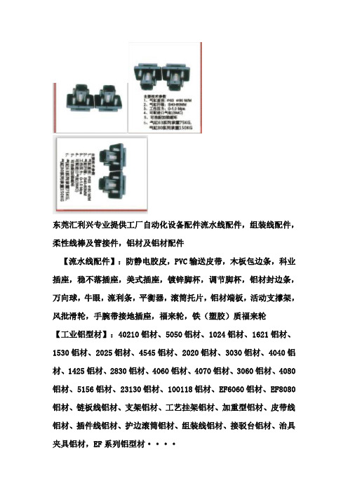
东莞汇利兴专业提供工厂自动化设备配件流水线配件,组装线配件,柔性线棒及管接件,铝材及铝材配件【流水线配件】:防静电胶皮,PVC输送皮带,木板包边条,科业插座,稳不落插座,美式插座,镀锌脚杯,调节脚杯,铝材封边条,万向球,牛眼,流利条,平衡器,滚筒托片,铝材端板,活动支撑架,风批滑轮,手腕带接地插座,福来轮,铁(塑胶)质福来轮【工业铝型材】:40210铝材、5050铝材、1024铝材、1621铝材、1530铝材、2025铝材、4545铝材、2020铝材、3030铝材、4040铝材、1425铝材、2830铝材、4060铝材、4070铝材、3060铝材、4080铝材、5156铝材、23130铝材、100118铝材、EF6060铝材、EF8080铝材、链板线铝材、支架铝材、工艺挂架铝材、加重型铝材、皮带线铝材、插件线铝材、护边滚筒铝材、组装线铝材、接驳台铝材、治具夹具铝材,EF系列铝型材····【组装线配件】:QX-1阻挡器、QX-2阻挡器、QX-3阻挡器、QX-4阻挡器、张紧座、倍速链条、三倍速链条、2.5倍速链条、FESTO阻挡器,SMC阻挡器,金器阻挡器,四导柱顶升气缸、卧式阻挡器、带电顶升转台、自动转台、导电槽、A-04导电轮、A-05B导电轮、导电轨,T型尼龙导条、定位珠、工装板导向轮、尼龙托轮、倍速铝材盖板、工装板挡条····【铝材连接件】:铝材封盖,铝材槽封边,方形拉手,尼龙合页,铝角码,锌合金角码,铁质角码,内置连接件,任意连接件,转向连接件,T型螺母,T型螺栓,方形螺母,LNT直角连接件,DNS角槽连接件,一字连接件,滑板螺母,菱形螺母,弧形螺母,DCB系列连接件,ASB系列连接件,ASC系列连接件,EF系列铝材连接件,FB铝材脚座····【输送机滚筒】:动力链轮滚筒、动力包胶滚筒、镀锌滚筒、无动力滚筒、PVC滚筒、锥度滚筒、锥度链轮滚筒、包胶滚筒、包胶电动滚筒、流水线头尾轮·····【精益管及连接件系列】:精益管,T0.8精益管,T1.0复合管、T1.2柔性线棒、柔性线棒,复合管,喷塑复合管,精益管连接件,复合管接头,金属接头,线棒连接件、HJ系列连接件······【工装板系列】PVC工装板、铝质工装板、耐高温工装板、电脑工装板、双层工装板、旋转工装板、TV工装板、、LCD工装板、冰箱工装板、洗衣机工装板、音响工装板、喇叭工装板、微波炉工装板、洗碗机工装板、洗衣机工装板、消毒柜工装板、热水器工装板、冷气机工装板、摩托车工装板、自行车工装板、家具工装板、空调工装板、燃气具工装板、电话机工装板、钢琴工装板、装配线工装板、老化线工装板,复印机工装板、传真机工装板、DVD工装板·····【插件线系列】:插件线专用铝导轨(51*56),手推插件线铝材,调整座,35B尼龙链条,06C尼龙链条,06C带侧导轮链条,06B带侧导轮链条,06C加长销碳钢(不锈钢)链条产品繁多、未能详列、欢迎各大使用厂商来电来函索取详细参数与资料。
电缆分支箱ac400v不带开关三路400a挂墙式smc外壳1进线2路出线母线系统挂接
国家电网公司湖北电网集中规模招标采购招标文件国网湖北公司配网标准化物资固化技术规范书0.4kV电缆分支箱,不带开关,三路,400A。
挂墙式,SMC外壳,1进线,2路出线,母线系统挂接(15GH-500021587-00002)2014年4月低压电缆分支箱采购标准技术规范使用说明1. 本采购标准技术规范分为标准技术规范通用部分、标准技术规范专用部分以及本规范使用说明。
2. 采购标准技术规范通用部分原则上不需要设备招标人(项目单位)填写,更不允许随意更改。
如对其条款内容确实需要改动,项目单位应填写项目单位通用部分条款变更表并加盖该网、省公司物资部(招投标管理中心)公章及辅助说明文件随招标计划一起提交至招标文件审查会。
经标书审查同意后,对通用部分的修改形成项目单位通用部分条款变更表,放入专用部分,随招标文件同时发出并视为有效。
3. 采购标准技术规范专用部分分为标准技术参数、项目单位需求部分和投标人响应部分。
标准技术参数表中“标准参数值”栏是标准化参数,不允许项目单位和投标人改动。
项目单位对“标准参数值”栏的差异部分,应填写项目单位技术差异表,“投标人保证值”栏应由投标人认真逐项填写。
项目单位需求部分由项目单位填写,包括招标设备的工程概况和招标设备的使用条件。
对扩建工程,可以提出与原工程相适应的一次、二次及土建的接口要求。
投标人响应部分由投标人填写投标人技术参数偏差表,提供销售业绩、主要部件材料和其他要求提供的资料。
4. 投标人填写技术参数和性能要求响应表时,如与招标人要求有差异时,除填写技术偏差表外,必要时应提供相应试验报告。
5. 有关污秽、温度、海拔等需要修正的情况由项目单位提出并在专用部分的项目单位技术差异表中明确表示。
6. 采购标准技术规范的页面、标题等均为统一格式,不得随意更改。
目次低压电缆分支箱采购标准技术规范使用说明 (3)第1部分通用技术规范 (6)1 总则 (6)1.1一般规定 (6)1.2投标人应提供的资格文件 (6)1.3适用范围 (7)1.4对设计图纸、说明书和试验报告的要求 (7)1.4.1图纸及图纸的认可和交付 (7)1.4.2说明书的要求 (8)1.4.3试验报告 (8)1.4.4图纸、说明书、试验报告等资料的交付时间、数量 (8)1.5标准和规范 (8)1.6投标人必须提交的技术参数和信息 (9)1.7备品备件 (9)1.8安装、调试、性能试验、试运行和验收 (9)2 结构及其他要求 (9)2.1低压电缆分支箱技术参数 (9)2.2低压电缆分支箱主要技术要求 (10)2.2.1外观、结构及工艺 (10)2.2.2母线和绝缘导线 (12)3 技术服务、工厂检验和监造 (15)3.1技术服务 (15)3.2工厂检验和监造 (15)第2部分专用技术规范 (17)1 标准技术参数表 (17)2 项目需求部分 (18)2.1 图纸资料提交单位 (19)2.2 工程概况 (19)2.3 使用条件 (19)2.4 可选技术参数表 (20)2.5 项目单位技术差异表 (20)3 投标人提供信息 (21)3.1 投标人技术偏差表 (22)3.2 投标人应提供的其他资料 (22)第1部分通用技术规范1 总则1.1 一般规定1.1.1投标人应具备招标公告所要求的资质,具体资质要求详见招标文件的商务部分。
转盘培训讲义
转盘培训讲义目录第1章概述 (1)1.1用途及特点 (1)1.2转盘技术参数 (1)第2章结构特点 ........................................................................错误!未定义书签。
第3章安装与调整 (4)3.1安装 (4)3.2调整 (4)第4章操作与使用 (4)4.1主补心装置与转台、补心的锁紧 (4)4.2转台的制动 (4)4.3转盘与滚子补心的配套使用方法 (5)第5章维护保养 (5)5.1润滑 (5)5.2日常维护检查项目 (6)5.3定期维护检查项目 (6)第6章包装、运输与贮存 (7)6.1包装、运输 (7)6.2贮存 (7)第7章轴承、专用工具、备件一览表 (8)7.1轴承 (8)7.2专用工具 (8)7.3备件 (8)第8章转盘用图 (9)8.1转盘结构图 (9)8.2转盘零部件明细表 (11)III第1章概述1.1 用途及特点转盘是钻机的重要部件,它的作用是在钻井作业时,通过一对锥齿轮副实现减速,使转台获得一定范围内的转速和扭矩输出,驱动钻具进行钻井作业;在起下钻和下套管时,转盘悬挂管柱.转盘在钻机钻进时,钻柱吊在水龙头下面,由转盘驱动方钻杆而旋转,起下钻和下套管时,管柱卡在转盘上方。
转盘应能承受钻机所允许的最大载荷,并能在承载旋转工作中,保证有足够的轴承寿命。
转盘的大小伞齿轮应能传递足够大的扭矩和功率。
转盘设计符合SY/T 5531《石油钻机用转盘》标准及API 7K规范。
目前,我公司生产ZP175 ZP205 ZP275 ZP375 ZP495系列转盘,ZP605转正在开发之中。
1.2 转盘技术参数在SY/T 5531-1992《石油钻机用转盘》标准规定了如表1所示的转盘的五个基本参数。
与SY/T 5531-1992《石油钻机用转盘》标准不同,API Spec 7K《钻井和修井设备规范》对表中最大静载荷、转台最大工作扭矩和转台最高转速未作具体要求,对这三个参数应理解为转盘所能达到的能力,换言之就是转盘的能力不得小于这三个基本参数的要求。
SMC电子停止器螺纹杆系列SP147X-019E-B说明书
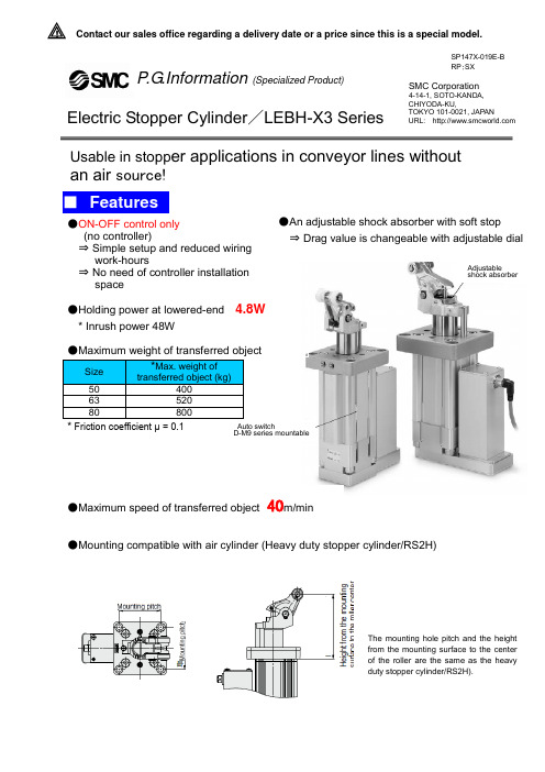
SP147X-019E-B RP :SX! Contact our sales office regarding a delivery date or a price since this is a special model.P .G .Information (Specialized Product)SMC Corporation4-14-1, SOTO-KANDA, CHIYODA-KU,TOKYO 101-0021, JAPANURL: Electric Stopper Cylinder /LEBH-X3 SeriesThe mounting hole pitch and the height from the mounting surface to the center of the roller are the same as the heavy duty stopper cylinder/RS2H).Shock absorberCarbon steelResinLock mechanismMotorTransfer directionTransfer direction Transfer directionMotorMotorMotorStandardLeverInstall/removalSet screw (M4)(Lever direction: opposite the motor side )Model SelectionLEBH 50□K-30T □-□-X3※ The graphs indicate the values at normal temperature.(20 to 25℃)LEBH 63-30T □-□-X3※ The graphs indicate the values at normal temperature.(20 to 25℃)LEBH 80-30T □-□-X3※ The graphs indicate the values at normal temperature.(20 to 25℃)How to OrderSpecificationsConstructionWhen cancel cap is usedDimensionsWork transfer directionM12 connectorConveyor upper limitPosition note2)(Roller center position)Work transfer directionConveyor lowerlimit position note2)When cancel cap is usedWith lock mechanism When cancel cap Is unusedF.G..terminal positionA-A(F.G .terminal)4×φ94×14 depth of counter bore 5Auto switch mounting surfaces (Can be mounted to theopposite surface) note34×φ94×14 depth of counter bore 5Manual override screwWork transfer directionLeverMotorNote 4) Lever direction of this drawing is opposite themotor side: E typeNote 1) Please note that the thickness of a mounting plate should be 10mmor less when this cylinder is mounted from the top (lever side) and ensure that the mounting plate does not interfere with the lever.Note 2) Please adjust the conveyor height within the range of the lower limitposition to the upper limit position.Note 3) The auto switch mounting surface is indicated above regardless oflever direction.Drawing Note4Work transfer direction4×φ114×18 depth of counter bore 6M12 connectorConveyor upper limitposition note2)(Roller center position)Work transfer directionConveyor lower limitposition note2)Auto switch mounting surfaces反対側面可 F.G.terminal positionA-A (F.G .terminal )With lock mechanism When cancel cap Is unusedWhen cancel cap is usedWork transfer directionLeverMotorAuto switch mounting surfaces(Can be mounted to theopposite surface)note3Drawing Note 44×φ114×18 depth of counter bore 6Manual override screwNote 1) Please note that the thickness of a mounting plate should be 10mmor less when this cylinder is mounted from the top (lever side) and ensure that the mounting plate does not interfere with the lever.Note 2) Please adjust the conveyor height within the range of the lower limitposition to the upper limit position.Note 3) The auto switch mounting surface is indicated above regardless oflever direction.Note 4) Lever direction of this drawing is opposite themotor side: E typeAuto switch mounting surfaces(Can be mounted to theopposite surface) note34×φ134×20 depth of counter bore 6Manual overridescrewWith lock mechanismWhen cancel capIs unusedWhen cancel cap is usedNote 1) Please note that the thickness of amounting plate should be 10mmor less when this cylinder is mountedfrom the top (lever side) and ensurethat the mounting plate does notinterfere with the lever.Note 2) Please adjust the conveyor heightwithin the range of the lower limitposition to the upper limit position.Note 3) The auto switch mounting surface isindicated above regardless oflever direction.Work transfer directionDrawingNote4Lever MotorLever detection switch(Proximity switch)/E2E-X2D1-NProximity switch specification/OMRON CorporationNote 1) At load current 100 mA and cord length of 2 mNote 2) Between case and whole charging part<Mounting position>Lever detectionswitch2-WireBrownBlue Dimensions Output CircuitBlueIndicator lightLever detectionswitchLeverTighteningnutTightening nutWasher with teethConfirm that the proximity switch indicator LED turns green when the lever is pushedtowards the proximity switch side. (Figure 1)Confirm that the proximity switch indicator LED turns green when the lever is pushedtowards the side opposite from the proximity switch. (Figure 2)Then, rotate the lever 90°to confirm that the indicator LED of the proximity switch(red, green) does not turn on.Fix the cylinder with the included screws after confirming that there is no interferencebetween the lever and the proximity switch.©2014 SMC CORPORATION All Rights ReservedAuto Switch mounting Auto Switch Proper mounting PositionNote )Adjust the auto switch after confirming the Operating conditions in the actual setting*Since the operating range is provided as a guideline Including hysteresis, it cannot be guaranteed. (assuming approximately ±30% dispersion)It may vary substantially depending on an ambient environment.! Caution To ensure the safest possible operation of this product, please be sure to thoroughly readthe “Safety Instructions” in our “Best Pneumatics” catalog before use.。
SMC SY3000 5000 7000 300 500机身端口 基座安装和维护手册说明书
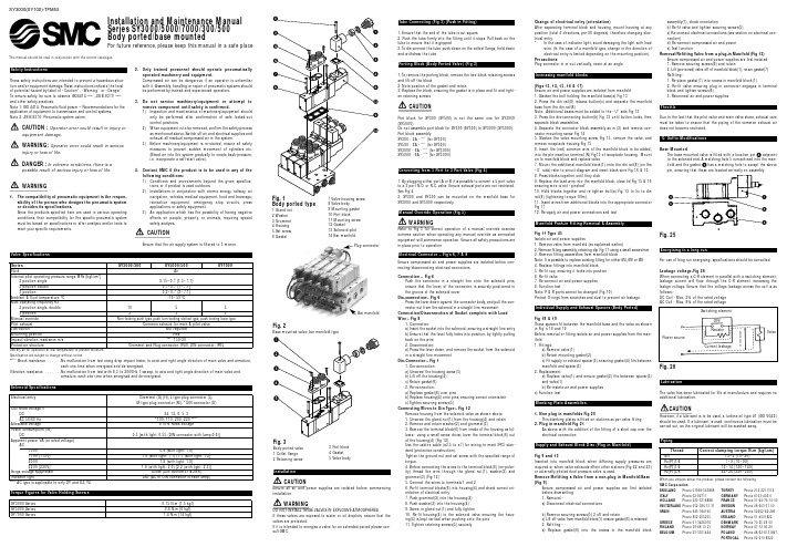
Installation and Maintenance Manual Series SY3000/5000/7000/300/500Body ported/base mountedThis manual should be read in conjunction with the current catalogueFor future reference,please keep this manual in a safe placeThese safety instructions are intended to prevent a hazardous situa-tion and/or equipment damage.These instructions indicate the level of potential hazard by label of “Caution”,“Warning”or “Danger”.To ensure safety,be sure to observe ISO4414 (Note1),JIS B 8370 (Note2)and other safety practices.Note 1:ISO 4414:Pneumatic fluid power – Recommendations for the application of equipment to transmission and control systems.Note 2:JIS B 8370:Pneumatic system axiom.CAUTION :Operator error could result in injury orequipment damage.WARNING:Operator error could result in serious injury or loss of life.DANGER :In extreme conditions, there is apossible result of serious injury or loss of life.1.The compatibility of pneumatic equipment is the respon-sibility of the person who designs the pneumatic system or decides its specifications.Since the products specified here are used in various operating conditions,their compatibility for the specific pneumatic systemmust be based on specifications or after analysis and/or tests to meet your specific requirements.2.Only trained personnel should operate pneumaticallyoperated machinery and equipment.Compressed air can be dangerous if an operator is unfamiliar with it.Assembly,handling or repair of pneumatic systems should be performed by trained and experienced operators.3.Do not service machinery/equipment or attempt toremove component until safety is confirmed.1) Inspection and maintenance of machinery/equipment shouldonly be performed after confirmation of safe locked-out control positions.2) When equipment is to be removed,confirm the safety processas mentioned above.Switch off air and electrical supplies and exhaust all residual compressed air in the system.3)Before machinery/equipment is re-started,ensure all safetymeasures to prevent sudden movement of cylinders etc.(Bleed air into the system gradually to create back-pressure,i.e.incorporate a soft-start valve).4.Contact SMC if the product is to be used in any of thefollowing conditions:1)Conditions and environments beyond the given specifica-tions,or if product is used outdoors.2)Installations in conjunction with atomic energy,railway,airnavigation,vehicles,medical equipment,food and beverage,recreation equipment,emergency stop circuits,press applications,or safety equipment.3)An application which has the possibility of having negativeeffects on people,property,or animals,requiring special safety analysis.Ensure that the air supply system is filtered to 5 micron.Series SY3000/300SY5000/500SY7000FluidAir Internal pilot operating pressure range MPa {kgf/cm 2}2 position single 0.15~0.7 {1.5~7.1}2 position double 0.1~0.7 {1~7.1}3 position0.2~0.7 {2~7.1}Ambient & fluid temperature °C -10~50°CMax operating frequency Hz2 position single,double 10553 position 333Manual override Non-locking push type,push turn-locking slotted type,push locking lever typePilot exhaust Common exhaust for main & pilot valveLubricationNot requiredMounting positionFree Impact/vibration resistance m/s Note 1)150/30Protection structureGrommet and Plug connector:IP40,DIN connector:IP65Use dry air for operation at low temperature to prevent moisture Specification are subject to change without noticeNote 1)Shock resistance . . . . . .No malfunction from test using drop impact tester,to exist and right angle direction of main valve and armature,each one time when energised and de-energised.Vibration resistance . . . . . . .No malfunction from test with 8.3 to 2000Hz 1 sweep,to axis and right angle direction of main valve andarmature,each one time when energised and de-energised.Electrical entryGrommet (G) (H),L type plug connector (L),M type plug connector (M),*DIN connector (D)Coil rated voltage VDC24,12,6,5,3AC 50/60 Hz *100,110,200,220 Note 2)Allowable voltage±10% rated voltagePower consumption (W)DC0.5 {with light:0.55 (DIN connector with lamp:0.6)}Apparent power VA (at rated voltage)AC100V0.9 (with light:1.0)110V {115V} 1.0 (with light:1.1) {1.1 (with light:1.2]200V1.8 (with light:1.9}220V [230V]1.9 (with light:2.0) [2.2 (with light:2.3)]Surge voltage suppressor Diode (DIN connector is ZNR)Indicator light LED (AC of DIN connector is neon lamp)Note 2)AC type is applicable to only DY and DZ,YZ.SY3000 Series 0.15 N.m {1.5 kgf}SY5000 Series 0.6 N.m {6 kgf}SY7000 Series1.4 N.m {14 kgf}26LubricationThe valve has been lubricated for life at manufacture and requires no additional lubrication.CAUTIONif a lubricant is to be used,a turbine oil type #1 (ISO VG32)should be used.If a lubricant is used,continuous lubrication must be carried out,as the original lubricant will be washed away.Thread Correct clamping torque N-m (kgf-cm)1.5~2 (15~20)Rc(PT)1/87~9 (70~90)Rc(PT)1/412~14 (120~140)Rc(PT)3/822~24 (220~240)Plug connectorBar manifoldSY3000(SY100)-TFM53When you enquire about the product,please contact the following SMC Corporation :ENGLAND Phone 01908-563888TURKEY Phone 212-2211512Phone 02-92711GERMANY Phone 6103-402-0Phone 020-*******FRANCE Phone 01-64-76-10-00SWITZERLAND Phone 052-396 31 31SWEDEN Phone 08-603 07 00Phone 945-184100AUSTRIA Phone 02262-62-280Phone 902-255255IRELAND Phone 01-4501822Phone 01-3426076DENMARK Phone 70 25 29 00Phone 09-68 10 21NORWAY Phone 67-12 90 20Phone 03-3551464POLAND Phone 48-22-6131847PORTUGAL Phone 02-610 8922Switching elementPower sourceCurrent leakageResistorValveV o l t a g e l e a k a g eOFFFig.5Fig.6Fig.8Using a 5 port valve as a 3 port valveSeries SY3/5/7000 may be use a N.C.or N.O.3 way valve by plugging one end of the A,B ports.Be sure not to plug the exhaust ports.Can be used when a double solenoid,3 way Fig.9Fig.10 Supply and Exhaust Block Fig.11Fig.12R PFig.13Fig.21Fig.22Fig.23Fig.24When supplying a manifold with more than one pressure,insert a block disk in between the stations subjected to different pressures.When a valve exhaust affects the other station in the circuit or when an externally piloted,dual pressure valve is used on a standard manifold,insert EXH block disc(s) in between stations to isolate the exhaust.Block disc indication sealThese seals are attached to the block when SUP and EXH block discs are fit-ted,for confirmation from outside.(3 sheets respectively)Note:When ordering block discs for installation at the factory,labels will be attached to the manifold showing the locations.ᕡᕢᕣᕤᕡᕢᕣᕤHook this section onto the DIN rail and press in the direction of the arrow until it clicks into positionNote:After inserting pins,lightly pull lead wires to check that the pins are locked.Note:Insert pins after removing the connector from the main unit.After inserting pins,lightly pull lead wires to check that the pins are locked.Note:Insert tab terminals fully.(Plug)(Plug)(Plug)(Plug)A4A4A4A4B2B2B2B2EA5 P1 EB3EA5 P1 EB3EA5 P1 EB3EA5 P1 EB3Note 1:When adding manifold bases to use more than 10stations,add SUP/EXH block assemblies,as well.Note 2:When bolt (a) for the end block is not sufficientlytightened during reassembly,air leakage may result.Before supplying air,check that there is no gap between blocks and that the manifold block is firm-ly fixed to the DIN rail in order to ensure air supply without leakage.Hook this part on the DIN rail and then press in the direction of the arrow until a click sound is produced.CAUTIONThe supply and exhaust ports may be fitted either at the lead wire end of the valve or the end plate side.If supplied factory-assem-bled they are fitted at the end plate side.Note:For protection of the wiring unit section from drain,pip-ing at the EA port shall be so arranged that it will not be directly exposed to exhaust from the valve.One-touch fittingsThe size of the ports on the SY manifolds (P ,A,B etc.),subplates,valves determines the pitch between the ports,permitting the use of one-touch fittings of the KJ series.However,some fittings of this series will cause clearance prob-lems depending on the type size.Please check catalogue for fit-ting dimensions before ordering.T i g h t e n i n gtorque1.65~2.5 N.mT i g h t e n i n g torque0.3~0.4 N.mTightening torque 0.2~0.25 N.mFig.18Fig.19Fig.20CAUTION1.Depending on the type of connector,solenoids that can be used.Manifold bases that can be added cannot exceed the number of usable solenoids.2.The manifold block assembly mounting position for addition of mani-fold bases is always on the U side,respective connectors sequentially from the D side.3.When bolt (a) for the end block is not sufficiently tightened during reassembly,air leakage may result.there is no gap between blocks and that the manifold block is firmly fixed to the DIN rail in order to ensure air supply without leakage.CAUTIONScrew tightening torque:M2:0.15 N-m M3:0.6 N-m M4:1.4 N-mCAUTIONInstalling DIN rail manifoldWhen DIN rail manifold for 45 and 45 type is installed on the place by bolt,fix it with 2 locations for 2-5 stations,locations for 6-10 stations,with 4 locations for 11-15 stations and with 5 locations for 16-20 stations.Unless DIN rail is fixed with less locations than our instructions,DIN rail and manifold might twisted and it causes trouble like air leakage.。
- 1、下载文档前请自行甄别文档内容的完整性,平台不提供额外的编辑、内容补充、找答案等附加服务。
- 2、"仅部分预览"的文档,不可在线预览部分如存在完整性等问题,可反馈申请退款(可完整预览的文档不适用该条件!)。
- 3、如文档侵犯您的权益,请联系客服反馈,我们会尽快为您处理(人工客服工作时间:9:00-18:30)。
【流水线配件】:防静电胶皮,PVC输送皮带,木板包边条,科业插座,稳不落插座,美式插座,镀锌脚杯,调节脚杯,铝材封边条,万向球,牛眼,流利条,平衡器,滚筒托片,铝材端板,活动支撑架,风批滑轮,手腕带接地插座,福来轮,铁(塑胶)质福来轮
【工业铝型材】:40210铝材、5050铝材、1024铝材、1621铝材、1530铝材、2025铝材、4545铝材、2020铝材、3030铝材、4040铝材、1425铝材、2830铝材、4060铝材、4070铝材、3060铝材、4080铝材、5156铝材、23130铝材、100118铝材、EF6060铝材、EF8080铝材、链板线铝材、支架铝材、
工艺挂架铝材、加重型铝材、皮带线铝材、插件线铝材、护边滚筒铝材、组装线铝材、接驳台铝材、治具夹具铝材,EF 系列铝型材····
【组装线配件】:QX-1阻挡器、QX-2阻挡器、QX-3阻挡器、QX-4阻挡器、张紧座、倍速链条、三倍速链条、2.5倍速链条、FESTO阻挡器,SMC阻挡器,金器阻挡器,四导柱顶升气缸、卧式阻挡器、带电顶升转台、自动转台、导电槽、A-04导电轮、A-05B导电轮、导电轨,T型尼龙导条、定位珠、工装板导向轮、尼龙托轮、倍速铝材盖板、工装板挡条····
【铝材连接件】:铝材封盖,铝材槽封边,方形拉手,尼龙合页,铝角码,锌合金角码,铁质角码,内置连接件,任意连接件,转向连接件,T型螺母,T型螺栓,方形螺母,LNT 直角连接件,DNS角槽连接件,一字连接件,滑板螺母,菱形螺母,弧形螺母,DCB系列连接件,ASB系列连接件,ASC 系列连接件,EF系列铝材连接件,FB铝材脚座····【输送机滚筒】:动力链轮滚筒、动力包胶滚筒、镀锌滚筒、无动力滚筒、PVC滚筒、锥度滚筒、锥度链轮滚筒、包胶滚筒、包胶电动滚筒、流水线头尾轮·····
【精益管及连接件系列】:精益管,T0.8精益管,T1.0复合管、T1.2柔性线棒、柔性线棒,复合管,喷塑复合管,精
益管连接件,复合管接头,金属接头,线棒连接件、HJ系列连接件······
【工装板系列】PVC工装板、铝质工装板、耐高温工装板、电脑工装板、双层工装板、旋转工装板、TV工装板、、LCD 工装板、冰箱工装板、洗衣机工装板、音响工装板、喇叭工装板、微波炉工装板、洗碗机工装板、洗衣机工装板、消毒柜工装板、热水器工装板、冷气机工装板、摩托车工装板、自行车工装板、家具工装板、空调工装板、燃气具工装板、电话机工装板、钢琴工装板、装配线工装板、老化线工装板,复印机工装板、传真机工装板、DVD工装板·····
【插件线系列】:插件线专用铝导轨(51*56),手推插件线铝材,调整座,35B尼龙链条,06C尼龙链条,06C带侧导轮链条,06B带侧导轮链条,06C加长销碳钢(不锈钢)链条。
