WP934GO2GD;中文规格书,Datasheet资料
IRFTS9342TRPBF;中文规格书,Datasheet资料
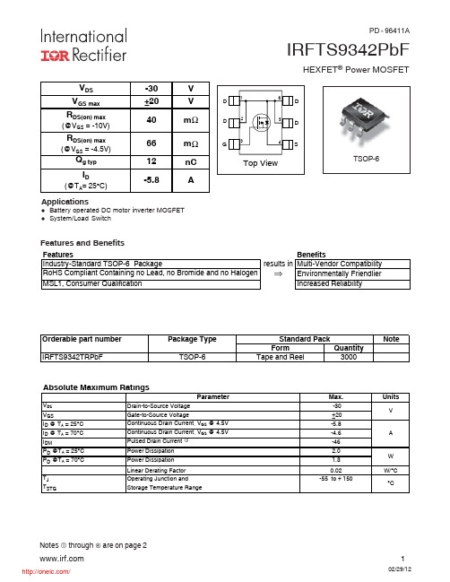
IRFTS9342PbFHEXFET ® Power MOSFETNotes through are on page 2Applicationsl Battery operated DC motor inverter MOSFET lSystem/Load SwitchFeatures and Benefitsresults in ⇒PD - 96411AIRFTS9342PbFNotes:Repetitive rating; pulse width limited by max. junction temperature. Pulse width ≤ 400μs; duty cycle ≤ 2%.When mounted on 1 inch square copper board.Static @ T = 25°C (unless otherwise specified)IRFTS9342PbFFig 4. Normalized On-Resistance vs. TemperatureFig 2. Typical Output CharacteristicsFig 1. Typical Output CharacteristicsFig 6. Typical Gate Charge vs.Gate-to-Source VoltageFig 5. Typical Capacitance vs.Drain-to-Source Voltage T J , Junction Temperature (°C)R D S (o n ) , D r a i n -t o -S o u r c e O n R e s i s t a n c e 110100-V DS , Drain-to-Source Voltage (V)10100100010000C , C a p a c i t a n c e (p F )0246810121416Q G Total Gate Charge (nC)0.02.04.06.08.010.012.014.0-V G S , G a t e -t o -S o u r c e V o l t a g e (V )DS -V DS , Drain-to-Source Voltage (V)0.1110100-I D , D r a i n -t o -S o u r c e C u r r e n t (A )IRFTS9342PbFFig 11. Maximum Effective Transient Thermal Impedance, Junction-to-CaseFig 8. Maximum Safe Operating AreaFig 9. Maximum Drain Current vs.Case TemperatureFig 7. Typical Source-Drain Diode Forward VoltageFig 10. Threshold Voltage vs. Temperature255075100125150T A , Ambient Temperature (°C)0123456-I D , D r a i n C u r r e n t (A)0.010.1110100V DS , Drain-to-Source Voltage (V)0.010.11101001000I D , D r a i n -t o -S o u r c e C u r r e n t (A)0.1110100-I S D , R e v e r s e D r a i n C u r r e n t (A )T J , Temperature ( °C )-V G S (t h ), G a t e t h r e s h o l d V o l t a g e (V )IRFTS9342PbFFig 12. On-Resistance vs. Gate VoltageFig 14. Maximum Avalanche Energy vs. Drain Current Fig 15. Typical Power vs. Time* Reverse Polarity of D.U.T for P-Channel* V GS = 5V for Logic Level Devices®2468101214161820-V GS, Gate -to -Source Voltage (V)255075100125150Starting T J , Junction Temperature (°C)020406080100120E A S , S i n g l e P u l s e A v a l a n c h e E n e r g y (m J )Time (sec)P o w e r (W )IRFTS9342PbFFig 17a. Gate Charge Test CircuitFig 17b. Gate Charge WaveformFig 18b. Unclamped Inductive WaveformsFig 18a. Unclamped Inductive Test CircuitFig 19b. Switching Time WaveformsFig 19a. Switching Time Test CircuitIdQgs1Qgs2Qgd QgodrV DDR DV DDI ASV DSV GSt t t tNote: For the most current drawing please refer to IR website at: /package/WW = (27-52) IF PRECEDED BY A LETTERYEA R Y Z52W WORK WEEK 26ZF = IRF5801(a s show n here) indica tes Lead-F ree.Note: A line above the w ork w eek G = IRF5803D = IRF5851E = IRF5852I = IRF 5805C = IRF5850N = IRF 5802K = IRF5810J = IRF5806H = IRF 5804S = Not a pplicable R = IRFTS 9342TRPBF T = IRLT S2242TRPBFIRFTS9342PbFTSOP-6 Tape and Reel Information† Qualification standards can be found at International Rectifier’s web site /product-info/reliability†† Higher qualification ratings may be available should the user have such requirements. Please contact your International Rectifier sales representative for further information: /whoto-call/salesrep/†††Applicable version of JEDEC standard at the time of product release.IR WORLD HEADQUARTERS: 101 N. Sepulveda Blvd., El Segundo, California 90245, USA Tel: (310) 252-7105TAC Fax: (310) 252-7903Visit us at for sales contact information . 02/2012Data and specifications subject to change without notice.8mmFEED DIRECTION4mmNOTES :1. OUTLINE CONFORMS TO EIA-481 & EIA-541.9.90 ( .390 )8.40 ( .331 )178.00( 7.008 ) MAX.NOTES:1. CONTROLLING DIMENSION : MILLIMETER.2. OUTLINE CONFORMS TO EIA-481 & EIA-541.Qualification information †分销商库存信息: IRIRFTS9342TRPBF。
WP934EB-2GD中文资料
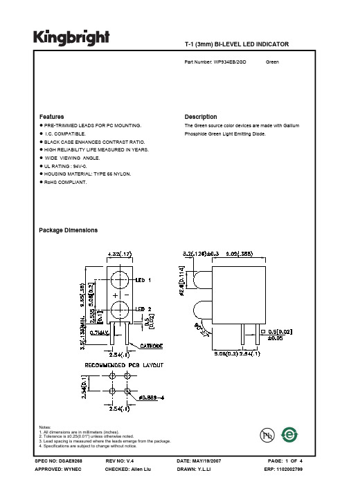
PACKING & LABEL SPECIFICATIONS
WP934EB/2GD
SPEC NO: DSAE9268 APPROVED: WYNEC
REV NO: V.4 CHECKED: Allen Liu
DATE: MAY/19/2007 DRAWN: Y.L.LI
PAGE: 4 OF 4 ERP: 1102002799
Green
WP934EB/2GD
SPEC NO: DSAE9268 APPROVED: WYNEC
REV NO: V.4 CHECKED: Allen Liu
DATE: MAY/19/2007 DRAWN: Y.L.LI
PAGE: 3 OF 4 ERP: 1102002799
元器件交易网
Notes: 1.Wavelength: +/-1nm. 2. Forward Voltage: +/-0.1V.
Absolute Maximum Ratings at TA=25°C
Parameter Power dissipation DC Forward Current Peak Forward Current [1] Reverse Voltage Operating/Storage Temperature Lead Solder Temperature [2] Lead Solder Temperature [3]
Electrical / Optical Characteristics at TA=25°C
Symbol λpeak λD [1] Δλ1/2 C VF [2] IR Parameter Peak Wavelength Dominant Wavelength Spectral Line Half-width Capacitance Forward Voltage Reverse Current Device Green Green Green Green Green Green Typ. 565 568 30 15 2.2 2.5 10 Max. Units nm nm nm pF V uA Test Conditions IF=20mA IF=20mA IF=20mA VF=0V;f=1MHz IF=20mA VR = 5V
ms934芯片手册

MS934芯片手册引言概述:本文旨在介绍MS934芯片,并提供详细的技术手册,以帮助读者更好地了解和使用该芯片。
MS934芯片是一款高性能的集成电路芯片,广泛应用于各种电子设备中。
通过本手册,读者将能够深入了解MS934芯片的功能特性、应用场景、工作原理等相关内容。
正文内容:1. MS934芯片的基本概述1.1 芯片的封装类型MS934芯片通常采用LQFP封装,方便安装和布局,同时具有良好的散热性能。
LQFP封装还提供了丰富的IO引脚数量和外部扩展接口,方便用户在应用中进行灵活连接。
1.2 芯片的主要功能MS934芯片具备高性能的处理器单元和丰富的外设功能,可提供多种功能实现的可能。
芯片内部集成了高速时钟电路、存储器控制器以及多种数字接口,能够满足复杂系统的需求。
1.3 芯片的主要规格参数内建8MB的Flash存储器和512KB的RAM,可支持大容量程序和数据存储。
工作频率可达200 MHz,提供强大的计算和处理能力。
支持多种数字接口,如UART、SPI、I2C等,满足不同的外设连接需求。
2. MS934芯片的应用场景2.1 智能家居领域MS934芯片能够提供稳定且高效的智能家居系统控制能力。
通过与各类传感器连接,实现对家庭环境的自动感知和调节,提升居住舒适度。
芯片的高性能处理能力和丰富的接口资源,可以满足智能家居中的复杂计算和通信需求。
2.2 工业自动化领域MS934芯片具备强大的实时控制能力和高速数据处理能力,非常适合用于工业自动化系统。
芯片支持多种高速通信接口,如以太网、CAN总线等,可实现与各类工控设备的联网。
同时,芯片提供了丰富的GPIO接口和模拟输入输出接口,方便连接和控制各类工业传感器和执行器。
2.3 汽车电子领域MS934芯片的高性能和可靠性使其成为汽车电子领域的理想选择。
芯片采用了低功耗设计,适应汽车电子系统对能效和环境适应性的要求。
可扩展的IO接口和丰富的外设功能,使芯片能够满足复杂的汽车电子系统集成和控制需求。
L10L10WL10+中文说明书路由器产品规格书-130516

l10l10wl10中文说明书路由器产品规格书130516产品需求规b40格说明书产品规格说明书路由器说明书路由器安装说明书腾达路由器说明书mw150r路由器说明书tp路由器说明书斐讯路由器说明书fw300r路由器说明书
3G无线路由器(产品规格书)
类型Type CDMA operating band BC0-800 BC6 IMT-2000 EVDO Rev.B: up to 14.7Mbps DL / 5.4Mbps UL EVDO Rev.A: up to3.1Mbps DL / 1.8Mbps L10+ L10W GSM operating band UMTS operating band gsm-850/Pgsm/Egsm-900 B1-2100 DCS-1800/PCS-1900 HSPA+ up to14.4Mbps DL HSDPA up to7.2Mbps DL HSUPA up to5.76Mbps UL
频段Band 硬件平台 Platform
传输速率 Transfer rate Wi-Fi
EDGE class 12, up to 236.8 Kbps 802.11b s 3000mAH 数据卡及对设备充电 对外部设备充电
Wi-Fi 传输速率 Transfer rate 锂离子 电池Battery Lithium ion 1*Micro USB 接口 1*Standard USB interface 2.0 1*RJ45 工作系统 Operation system WEB界面
WAN口(支持DHCP、Static IP、ADSL)
工作系统 Windows / Mac OS /IOS /Android Operation system 工作浏览器 Internet Explorer/Mozilla Firefox/Google Chrome/Safari Operation Browser 备注 L10W和L10WE暂不支持850频段,如需国外发样和定制需提前说明,再把850频段添加进去
APM9435规格书

ANPEC reserves the right to make changes to improve reliability or manufacturability without notice, and advise customers to obtain the latest version of relevant information to verify before placing orders.Pin DescriptionOrdering and Marking InformationFeaturesApplications• Power Management in Notebook Computer,Portable Equipment and Battery Powered SystemsSO − 8• -30V/-4.6A, R DS(ON) = 52m Ω(typ.) @ V GS = -10VR DS(ON) = 80m Ω(typ.) @ V GS = -4.5V• Super High Density Cell Design • Reliable and Rugged • SO-8 PackageAbsolute Maximum Ratings (T A = 25°C unless otherwise noted)S S S GDD D D P-Channel MOSFETGA P M 9435H a n d lin g C o d e T e m p. R a n g e P a c k a g e C o d eP a c k a g e C o d e K : S O -8O p e ra tio n J u n c tio n T e m p. R a n g e C : -55 to 150°C H a n d lin g C o d e T U : T u b eT R : T a p e & R e e lA P M 9435A P M 9435X X X X XX X X X X - D a te C o d eElectrical Characteristics (T A = 25°C unless otherwise noted)Absolute Maximum Ratings (T A = 25°C unless otherwise noted)Notesa : Guaranteed by design, not subject to production testing b: Pulse test ; pulse width ≤300µs, duty cycle ≤ 2%0.02.55.07.510.012.515.017.520.00.000.020.040.060.080.100.120.140.1602468105101520-50-2502550751001251500.000.250.500.751.001.251.50123455101520Typical Characteristics-I D -D r a i n C u r r e n t (A )Transfer Characteristics-V GS - Gate-to-Source Voltage (V)Threshold Voltage vs. Junction T emperatureTj - Junction T emperature (°C)-V G S (t h )-T h r e s h o l d V o l t a g e (V )(N o r m a l i z e d )On-Resistance vs. Drain Current-I D - Drain Current (A)R D S (o n )-O n -R e s i s ta n c e (Ω)Output Characteristics-I D -D r a i n C u r r e n t (A )-V DS- Drain-to-Source Voltage (V)0510********200400600800123456789100.000.050.100.150.200.250.3005101520250246810-50-2502550751001251500.000.250.500.751.001.251.501.752.00Typical Characteristics-V GS - Gate-to-Source Voltage (V)R D S (o n )-O n -R e s i s t a n c e (Ω)On-Resistance vs. Gate-to-Source VoltageR D S (o n )-O n -R e s i s t a n c e (Ω)(N o r m a l i z e d )On-Resistance vs. Junction TemperatureT J - Junction T emperature (°C)-V DS - Drain-to-Source Voltage (V)CapacitanceC a p a c i t a n c e (p F )Gate ChargeQ G - Gate Charge (nC)-V G S -G a t e -S o u r c e V o l t a g e (V )0.010.111001020304050607080301E-41E-30.010.11100.010.11300.00.20.40.60.8 1.0 1.2 1.4 1.6 1.80.111020Typical CharacteristicsSingle Pulse Power Time (sec)Square Wave Pulse Duration (sec)N o r m a l i z e d E f f e c t i v e T r a n s i e n tT h e r m a l I m p e d a n c eNormalized Thermal Transient Impedence, Junction to AmbientP o w e r (W )Source-Drain Diode Forward Voltage-V SD -Source-to-Drain Voltage (V )-I S -S o u r c e C u r r e n t (Α)Packaging InformationSOP-8 pin ( Reference JEDEC Registration MS-012)Reflow Condition (IR/Convection or VPR Reflow)Physical SpecificationsPre-heat temperature183 CPeak temperatureTime°t e m p e r a t u r eClassification Reflow ProfilesPackage Reflow ConditionsReliability test programCover Tape DimensionsCustomer ServiceAnpec Electronics Corp.Head Office :5F, No. 2 Li-Hsin Road, SBIP,Hsin-Chu, Taiwan, R.O.C.T el : 886-3-5642000Fax : 886-3-5642050Taipei Branch :7F, No. 137, Lane 235, Pac Chiao Rd.,Hsin Tien City, Taipei Hsien, Taiwan, R. O. C.T el : 886-2-89191368Fax : 886-2-89191369。
AR9344吸顶AP+MT7620N入墙AP规格书

MT7620N入墙式AP规格技术书
产品规格
硬件配置 主芯片 无线技术 Memory Flash MT7620N 300Mbps 无线AP专业芯片 802.11N, 2T2R 300M MIMO技术 32MB DDR RAM 4MB 2个10/100 Mbps自适应有线网络接口 1 个复位按钮,可恢复出厂设置 一个电源开关 一个RJ11接入接口 一个USB接口支持5V—1A直流输出 2.4G 全向高增益2.0 dBi内置天线 <8 W 长86.0 mm ,宽86.0mm,高 33.7mm 93g 24VPOE交换机供电(标配不含poe电源) 802.11b/g/n: 2.4~2.4835GHz 韩国、日本、ETSI、FCC通信信道可选 OFDM = BPSK,QPSK, 16-QAM, 64-QAM DSSS = DBPSK, DQPSK, CCK 300 Mbps 11n : -70dBm@10% PER 11g : -70dBm@10% PER 11b : -85dBm@8% PER 802.11n:15dBm for OFDM mode 802.11g: 17dBm for OFDM mode 802.11b: 20dBm fro CCK mode 网关模式/AP模式/万能中继模式 IEEE 802.3(Ethernet) IEEE 802.3u(Fast Ethernet) IEEE 802.11b/g/n(2.4G WLAN) 自动信道选择 多距离控制802.1x ACK时间输出 多SSID,最多可配置4个SSID WEP 安全机制支持64/128/152 位WEP安全密码 WPA/WPA2 安全机制(WPA-PSK 使用TKIP 或AES) WPA/WPA2 安全机制(WPA-EAP 使用TKIP) 隐藏SSID 安全机制 支持PC集中管理 支持功率可调、用户接入个数限制、覆盖阀值 WEB配置(HTTP/远程登陆) WEB 网页或者TFTP来升级软件 可配置用户和密码 设备和网络状态统计
ASD934无线充智能测试设备用户手册说明书
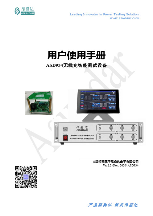
©版权归属于昂盛达电子有限公司Ver2.0 /Nov, 2020/ ASD934简介在某些情况下,用错误配置的市电电压为设备供电可能造成市电保险丝断开。
2.2 前面板介绍图 2.2:ASD934前面板图 2.3:ASD934后面板图 2.4.1:ASD934安卓触控屏图4.1.1 研发模式研发模式可以显示输入给无线充发射器的电压、电流、功率及D+、D-值,和显示无线充接收器提供给负载的电压、电流及功率值。
可同时或单独使用发射端或接收端,同时使用时可显示实时转换效率。
电源供电支持标准(无协议)、QC协议、PD协议三种方式,电压范围0~20V流所允许的上限值可设定。
负载受电可选择QI、Samsung、Apple和EPP标准,均支持5W、7.5W、10W四种功率选择,可测量电压范围0~20V,电流范围0~ 2A。
4.2自动模式无线充测试仪的自动模式主界面如图图4.2.1 自动模式每一项测试工序均可设置电源和负载两种功能,电源可选择标准、QC或PD协议,负载、Samsung、Apple和EPP标准。
可设置电源电压、最大输入电流、负载功率等多项参数,可设定发射和接收的参数范围作为判定指标。
保存好的工步条件可单步调试或复制粘贴、编辑、删除;自动测试按序号依次进行,可长按序号拖动进行自由排序;多道工序可保存为一个项目,项目数据可导出或导入至存储设备。
界面如图4.2.2所示。
图4.2.2 参数设置图5.1.1 开机启动界面点击操作终端右侧“设置”图标,弹出设置面板,如图5.1.2所示。
图5.1.2 设置面板“模式切换”图标即弹出模式切换窗口,可选择自动或研发两种工作模式,如图5.1.3所示。
图5.1.3 模式切换5.2研发模式图5.2.1 研发模式5.1章节的流程,正确连接测试线和无线充接收座并开机后,将发射端的测试线连接无线充发射器的电源输入接口,并将无线充接收座线圈位置正对于发射器线圈,应保持发射器线圈和接收器线圈位于同一中心轴上。
WTD93LG 用户手册说明书
本产品的用户使用手册文档版权归上海辉度智能系统有限公司所有,其保留所有权力。
上海辉度智能系统有限公司有权利在任何时间改进本文档涉及的产品内容。
任何个人或公司都不允许再版、拷贝、翻译及传播本文档的任何部分。
郑重承诺:凡上海辉度智能系统有限公司产品从购买即日起一年内无任何材料性缺损。
凡使用本系列产品除产品质量所造成的损害,上海辉度智能系统有限公司不承担任何法律责任。
上海辉度智能系统有限公司有义务提供本系列产品可靠而详尽资料,但保留修订权利,且不承担使用者非法利用资料对第三方所造成侵害构成的法律责任。
如果你有任何的问题,欢迎联系我们,我们会尽快回答您的问题。
公司:上海辉度智能系统有限公司网址:电话:(86-21)37774020传真:(86-21)37774010邮编:201100邮箱:****************地址:上海闵行区中春路7001号明谷科技园目录第一章基本介绍 (2)1.1概述 (3)第二章产品安装配置 (4)2.1产品正面图 (5)2.1.1安装尺寸 (5)2.1.2产品配件清单 (6)2.1.3产品安装向导 (7)第三章模块功能简介 (8)3.1功能参数说明 (9)3.1.1系统参数 (9)3.1.2端子功能描述 (10)3.1.3LED灯说明 (10)3.1.4技术规范 (10)第一章1.1概述WTD93LG网关是一款与Bosch的TDL模块联合使用,形成货物运输情况监控以及存储的一体解决方案。
WTD93LG通过低功耗蓝牙BLE协议采集Bosch的TDL采集到的震动,温湿度信息。
WTD93LG的GPS的定位系统快速定位运输过程中的温湿度异常变化,或者剧烈震动的地方,并通过无线通信技术向服务器定时发送采集到的数据。
WTD93LG网关内部集成了高性能和超低功耗为一体的CPU,具有快速的数据交换及逻辑处理能力。
射频核心硬件由世界知名通信厂商设计生产,具有很高的网络稳定性,内置看门狗保证设备运行安全可靠。
L934SRD12V中文资料

Description
The Super Bright Red source color devices are made with Gallium Aluminum Arsenide Red Light Emitting Diode.
INTERNAL RESISTOR.
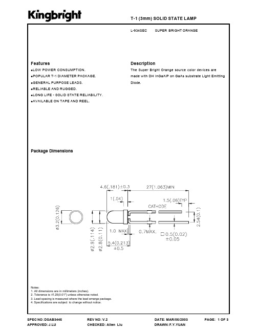
Package Dimensions
Notes: 1. All dimensions are in millimeters (inches). 2. Tolerance is ±0.25(0.01") unless otherwise noted. 3. Lead spacing is measured where the lead emerge package. 4. Specifications are subject to change without notice.
元器件交易网
T-1 (3mm) SOLID STATE LAMP
L-934SRD-12V SUPER BRIGHT RED
Features
!LOW POWER CONSUMPTION. !POPULAR T-1 DIAMETER PACKAGE. !GENERAL PURPOSE LEADS. !RELIABLE AND RUGGED. ! LONG LIFE - SOLID STATE RELIABILITY. !12V
Note: 1. θ1/2 is the angle from optical centerline where the luminous intensity is 1/2 the optical centerline value.
Electrical Maximum Ratings at T)=25°C °
ASD934无线充智能测试设备 用户使用手册说明书

用户使用手册ASD934无线充智能测试设备©版权归属于昂盛达电子股份有限公司Ver2.0/Nov,2020/ASD934注意事项◆感谢您购买和使用我司产品!本用户手册适用于ASD934无线充智能测试设备产品。
在使用前,请认真阅读本手册。
◆收到产品后请仔细检查产品外观、型号、合格证、用户手册及保修单等附件是否齐全。
若有问题请及时与经销商或我司联系;若发现产品外观破损,请勿通电使用,以免引发触电事故。
◆在使用过程中请严格遵守各项安全规范,若忽视或不遵守相关规范进行操作,将可能影响仪器性能,导致仪器损坏,甚至危及人身安全。
对不遵守安全规范而导致的任何后果,我司不予承担。
◆非专业人员请勿打开机箱,请勿擅自对仪器内部电路及元件进行更换或调整。
◆请在安全环境下使用,在通电前请确认输入电源的参数是否符合要求。
◆本手册所描述的可能并非产品的全部内容。
我司有权对本产品的性能、功能、内部结构、外观、附件等进行更改,对用户手册进行更新而不另行通知。
本手册最终解释权归我司所有。
◆公司产品会不断升级,请以实际产品为准。
◆客服电话:400-1656-165Leading Innovator in Power Testing Solution目录第一章验货安装 (5)1.1验货 (5)1.2清洁 (5)1.3连接部分的安装 (5)1.4安装尺寸 (5)1.5安装位置 (5)第二章快速入门 (6)2.1自检 (6)2.2前面板介绍 (7)2.3后面板介绍 (7)2.4触控屏介绍 (8)第三章技术规格 (9)第四章功能特性 (10)4.1研发模式 (10)4.2自动模式 (11)第五章基本操作 (12)5.1开机 (12)5.2研发模式 (14)5.3自动模式 (14)5.3.1参数设置 (15)5.3.2测试选项 (21)5.3.3启动测试 (22)5.3.4导出报表 (23)5.4其他功能 (24)第六章设备接口 (27)6.1前面板接口 (27)6.2后面板接口 (27)6.3触控屏接口 (28)第六章常见问题 (29)第七章保修协议 (15)简介ASD934无线充智能测试设备由测试仪及触控屏两部分组成,集快充电源、电子负载功能于一体。
WP934GO-2ID中文资料

Units mW mA mA V
SPEC NO: DSAF1885 APPROVED: WYNEC
REV NO: V.2 CHECKED: Allen Liu
DATE: MAY/22/2007 DRAWN: Y.L.LI
ቤተ መጻሕፍቲ ባይዱ
PAGE: 2 OF 4 ERP: 1102003098
元器件交易网
SPEC NO: DSAF1885 APPROVED: WYNEC
REV NO: V.2 CHECKED: Allen Liu
DATE: MAY/22/2007 DRAWN: Y.L.LI
PAGE: 1 OF 4 ERP: 1102003098
元器件交易网
Selection Guide
Part No. Dice Lens Type Iv (mcd) [2] @ 10mA Min. WP934GO/2ID High Efficiency Red (GaAsP/GaP) RED DIFFUSED 8 Typ. 20 Viewing Angle [1] 2θ1/2 40°
Notes: 1. θ1/2 is the angle from optical centerline where the luminous intensity is 1/2 the optical centerline value. 2. Luminous intensity/ luminous Flux: +/-15%.
元器件交易网
T-1 (3mm) BI-LEVEL LED INDICATOR
Part Number: WP934GO/2ID High Efficiency Red
Features
PRE-TRIMMED LEADS FOR PC MOUNTING. I.C. COMPATIBLE. BLACK CASE ENHANCES CONTRAST RATIO. HIGH RELIABILITY LIFE MEASURED IN YEARS. WIDE VIEWING ANGLE. UL RATING : 94V-0. HOUSING MATERIAL: TYPE 66 NYLON. RoHS COMPLIANT.
BFT92W,115;中文规格书,Datasheet资料

2
45 o
MLB548
1.0
90 o
VCE = 10 V; IC = 15 mA.
Fig.10 Common emitter input reflection coefficient (s11), typical values.
90 o
135 o
45 o
180 o
40 MHz 50 40 30 20 10 3 GHz
Fig.6
Gain as a function of collector current, typical values.
Fig.7
Gain as a function of collector current, typical values.
50 gain (dB) 40 G UM 30 MSG
MLB546
1 C re (pF) 0.8
6 fT (GHz) 4 V CE = 10 V 5V
MLB543
0.6
0.4
2
0.2
0 0 4 8 12 16 20 VCB (V)
0 1 10 I C (mA) 10 2
IC = 0; f = 1 MHz.
f = 500 MHz; Tamb = 25 C.
Fig.4
DISCRETE SEMICONDUCTORS
DATA SHEET
BFT92W PNP 4 GHz wideband transistor
Product specification May 1994
/
NXP Semiconductors
Product specification
0 0 10 20 I C (mA) 30
VCE = 10 V; Tj = 25 C.
AR9344_datasheet

COMPANY CONFIDENTIAL • 1Data Sheet© 2010–2011 by Atheros Communications, Inc. All rights reserved. Atheros®, Atheros Driven®, Align®, Atheros XR®, Driving the Wireless Future®, Intellon®, Ethos®, IQUE®, No New Wires®, Orion®, PLC4Trucks®, Powerpacket®, Spread Spectrum Carrier®, SSC®, ROCm®, Super A/G®, Super G®, Super N®, The Air is Cleaner at 5-GHz®, Total 802.11®, U-Nav®, Wake on Wireless®, Wireless Future. Unleashed Now.®, and XSPAN®, are registered by Atheros Communications, Inc. Atheros SST™, Signal-Sustain Technology™, Install N Go™, ROCm™, amp™, Simpli-Fi™, There is Here™, U-Map™, U-Tag™, and 5-UP™ are trademarks of Atheros Communications, Inc. The Atheros logois a registered trademark of Atheros Communications, Inc. All other trademarks are the property of their respective holders. Subject to change without notice.November 2011AR9344 Highly-Integrated and Feature-Rich IEEE 802.11n 2x2 2.4/5 GHz Premium SoC for Advanced WLAN PlatformsGeneral DescriptionThe Atheros AR9344 is a highly integrated and feature-rich IEEE 802.11n 2x2 2.4/5 GHz System-on-a-Chip (SoC) for advanced WLAN platforms. It includes a MIPS 74Kc processor, PCI Express 1.1 Root Complex and Endpoint interfaces, five port IEEE 802.3 Fast Ethernet Switch with MAC/PHY, one MII/RGMII interface, one USB 2.0 MAC/PHY, and external memory interface for serial Flash, DDR1 or DDR2, I 2S/SPDIF-Out audio interface, SLIC VOIP/PCM interface, two UARTs, and GPIOs that can be used for LED controls or other general purpose interface configurations.The AR9344 supports 802.11n operations up to 144 Mbps for 20 MHz and 300 Mbps for 40 MHz respectively, and 802.11a/b/g data rates.Additional features include Maximal Likelihood (ML) decoding, Low-Density Parity Check (LDPC), Maximal Ratio Combining (MRC), Tx Beamforming (TxBF), and On-Chip One-Time Programmable (OTP) memory.The AR9344 PCIE Root Complex interface can be used to connect to another Atheros single-chip MAC/BB/radio for dual concurrent WLANapplications. The AR9344 supports booting from either NOR or NAND flash. If NOR flash is used as boot codestore, an additional NAND flash device can still be connected, for end-user multi-media storage and other applications.When connecting the AR9344 to an external host through the PCIE Endpoint interface, or the USB Device interface, the AR9344 can off load the hostCPU from computation- intensive functions, allowing it to focus on its dedicated tasks.Features■74Kc MIPS processor with 64 KB I-Cache and 32 KB D-Cache, operating at up to 560 MHz ■External 16- or 32-bit DDR1, DDR2 operating at up to 225 MHz (450 M transfers/sec)■NAND and SPI NOR Flash memory support ■10/100 Ethernet Switch with five IEEE 802.3 Ethernet LAN ports ■MII/RGMII interface■802.3az Energy Efficient Ethernet compliant ■Hardware-based NAT & ACL accelerators for Ethernet interface■Both PCI Express 1.1 Root Complex and Endpoint interfaces supported simultaneously■One USB 2.0 controller with built-in MAC/ PHY supports Host or Device mode■Boot from external CPU via PCIE, USB, xMII, eliminating need for external flash ■I 2S/SPDIF-out audio interface ■SLIC for VOIP/PCM■One low-speed UART (115 Kbps), one high-speed UART (3 Mbps), and multiple GPIO pins for general purpose I/O■Fully integrated RF Front-End including PAs and LNAs■Optional external LNA/PA■25 MHz or 40 MHz reference clock input ■ 1.2 V switching regulator■Advanced power management with dynamicAR9344 System Block Diagram。
L-934SEC资料
Su p er B r ig h t Or an g e 75 30 195 5 -40°C To +85°C 260°C For 5 Seconds
Un its mW mA mA V
Note: 1. θ1/2 is the angle from optical centerline where the luminous intensity is 1/2 the optical centerline value.
Electrical / Optical Characteristics at TA=25°C °
Sy m b o l λpeak λD ∆λ1/2 C VF IR P ar am et er Peak Wavelength Dominate Wavelength Spectral Line Half-width Capacitance Forward Voltage Reverse Current D ev i c e Super Bright Orange Super Bright Orange Super Bright Orange Super Bright Orange Super Bright Orange Super Bright Orange Ty p . 610 601 29 30 2.0 2.5 10 Max . Un its nm nm nm pF V uA Tes t Co n d it io n s IF = 2 0 m A IF = 2 0 m A IF = 2 0 m A V F = 0 V;f= 1 M Hz IF = 2 0 m A VR = 5V
TDR934系列电动机综合保护装置技术说明书V230

南 京 钛 能 电 气 有 限 公 司
N A N J I N G T A L E N T E L E C T R I C C O . , LT D .
V2.3 0510-2011
Hale Waihona Puke 目1. 2. 3. 4.
录
第一部分 技术说明书 ................................................................................................................................... 1 简介 ......................................................................................................................................................... 2 特点 ......................................................................................................................................................... 3 应用 ......................................................................................................................................................... 3 保护原理 ................................................................................................................................................. 4 4.1. 4.2. 4.3. 4.4. 4.5. 4.6. 4.7. 4.8. 4.9. 4.10. 4.11. 4.12. 4.13. 4.14. 4.15. 4.16. 4.17. 4.18. 4.19. 4.20. 5. 电动机用电流速断保护 ............................................................................................................. 4 过电流保护 ................................................................................................................................. 4 过负荷保护 ................................................................................................................................. 5 负序过流保护 ............................................................................................................................. 5 过热保护 ..................................................................................................................................... 5 过热禁止再启动保护 ................................................................................................................. 6 启动过长保护 ............................................................................................................................. 6 堵转保护 ..................................................................................................................................... 7 过压保护 ..................................................................................................................................... 7 低压保护 ..................................................................................................................................... 7 零序过流保护 ............................................................................................................................. 8 零序过压保护 ............................................................................................................................. 8 TV 断线检测............................................................................................................................... 8 开关位臵监视 ............................................................................................................................. 9 IEC 反时限曲线特性.................................................................................................................. 9 比率差动保护 ........................................................................................................................... 10 二次谐波制动的比率差动保护 ............................................................................................... 11 TA 断线判别及差流监视元件 ................................................................................................. 11 差流速断保护 ........................................................................................................................... 11 磁平衡电流差动保护 ............................................................................................................... 11
MAX931-MAX934中文资料

MAX931-MAX934
______________Ordering Information
PART MAX931CPA MAX931CSA MAX931CUA MAX931EPA MAX931ESA TEMP. RANGE 0°C to +70°C 0°C to +70°C 0°C to +70°C -40°C to +85°C -40°C to +85°C PIN-PACKAGE 8 Plastic DIP 8 SO 8 µMAX 8 Plastic DIP 8 SO
INTERNAL COMPARATORS INTERNAL 2% PER HYSTERESIS REFERENCE PACKAGE PACKAGE
____________________________Features
o Ultra-Low 4µA Max Quiescent Current Over Extended Temp. Range (MAX931) o Power Supplies: Single +2.5V to +11V Dual ±1.25V to ±5.5V o Input Voltage Range Includes Negative Supply o Internal 1.182V ±2% Bandgap Reference o Adjustable Hysteresis o TTL-/CMOS-Compatible Outputs o 12µs Propagation Delay (10mV Overdrive) o No Switching Crowbar Current o 40mA Continuous Source Current o Available in Space-Saving µMAX Package
是德 N9340B 手持式频谱分析仪 用户手册说明书

是德N9340B手持式频谱分析仪请注意:安捷伦电子测量仪器部已经转为是德科技有限公司。
关于此方面详细信息,请访问用户手册Notices© Keysight Technologies, Inc. 2008-2014No part of this manual may be reproduced in any form or by any means (including electronic storage and retrieval or translation into a foreign language) without prior agreement and written consent from Keysight Technologies, Inc. as governed by United States and international copyright laws. Trademark AcknowledgmentsManual Part NumberN9340-90007EditionEdition 2, July 2014Printed in ChinaPublished by:Keysight TechnologiesNo 116 Tianfu 4th street Chiengdu, 610041 C hina WarrantyTHE MATERIAL CONTAINED IN THIS DOCUMENT IS PROVIDED “AS IS,” AND IS SUBJECT TO BEING CHANGED, WITHOUT NOTICE, IN FUTURE EDITIONS. FURTHER, TO THE MAXIMUM EXTENT PERMITTED BY APPLICABLE LAW, KEYSIGHT DISCLAIMS ALL WARRANTIES, EITHER EXPRESS OR IMPLIED WITH REGARD TO THIS MANUAL AND ANY INFORMATION CONTAINED HEREIN, INCLUDING BUT NOT LIMITED TO THE IMPLIED WARRANTIES OF MERCHANTABILITY AND FITNESS FOR A PARTICULAR PURPOSE. KEYSIGHT SHALL NOT BE LIABLE FOR ERRORS OR FOR INCIDENTAL OR CONSEQUENTIAL DAMAGES IN CONNECTION WITH THE FURNISHING, USE, OR PERFORMANCE OF THIS DOCUMENT OR ANY INFORMATION CONTAINED HEREIN. SHOULD KEYSIGHT AND THE USER HAVE A SEPARATE WRITTEN AGREEMENT WITH WARRANTY TERMS COVERING THE MATERIAL IN THISDOCUMENT THAT CONFLICT WITHTHESE TERMS, THE WARRANTYTERMS IN THE SEPARATEAGREEMENT WILL CONTROL.Technology LicensesThe hardware and/or softwaredescribed in this document arefurnished under a license and may beused or copied only in accordancewith the terms of such license.U.S. Government RightsThe Software is “commercialcomputer software,” as definedby Federal Acquisition Regulation(“FAR”) 2.101. Pursuant to FAR12.212 and 27.405-3 andDepartment of Defense FARSupplement (“DFARS”) 227.7202,the U.S. government acquirescommercial computer softwareunder the same terms by whichthe software is customarilyprovided to the public.Accordingly, Keysight providesthe Software to U.S. governmentcustomers under its standardcommercial license, which isembodied in its End User LicenseAgreement (EULA), a copy ofwhich can be found at/find/sweulaThe license set forth in the EULArepresents the exclusive authorityby which the U.S. governmentmay use, modify, distribute, ordisclose the Software. The EULAand the license set forth therein,does not require or permit,among other things, thatKeysight: (1) Furnish technicalinformation related tocommercial computer softwareor commercial computersoftware documentation that isnot customarily provided to thepublic; or (2) Relinquish to, orotherwise provide, thegovernment rights in excess ofthese rights customarily providedto the public to use, modify,reproduce, release, perform,display, or disclose commercialcomputer software orcommercial computer softwaredocumentation. No additionalgovernment requirementsbeyond those set forth in theEULA shall apply, except to theextent that those terms, rights, orlicenses are explicitly requiredfrom all providers of commercialcomputer software pursuant tothe FAR and the DFARS and areset forth specifically in writingelsewhere in the EULA. Keysightshall be under no obligation toupdate, revise or otherwisemodify the Software. Withrespect to any technical data asdefined by FAR 2.101, pursuantto FAR 12.211 and 27.404.2 andDFARS 227.7102, the U.S.government acquires no greaterthan Limited Rights as defined inFAR 27.401 or DFAR 227.7103-5(c), as applicable in any technicaldata.Safety NoticesA CAUTION notice denotes a hazard. Itcalls attention to an operatingprocedure, practice, or the like that,if not correctly performed or adheredto, could result in damage to theproduct or loss of important data. Donot proceed beyond a CAUTIONnotice until the indicated conditionsare fully understood and met.A WARNING notice denotes a hazard.It calls attention to an operatingprocedure, practice, or the like that,if not correctly performed or adheredto, could result in personal injury ordeath. Do not proceed beyond aWARNING notice until the indicatedconditions are fully understood andmet.目录1N9340B简介介绍 2前端面板概述 4顶部面板概述 5显示屏标注 62使用指南检查货品包装和装箱清单 10电源要求 11交流电源线规格 12安全须知 13安装电池 16使用提示 18准备工作 19进行基本测量 20联系是德科技 243系统设置调节视觉效果和声音 26系统设置 27文件 29系统信息 32错误信息 33时基校准 34默认出厂设置 354开始测量测量多个信号 38测量低电平信号 43改善频率分辨率和精确度 48测量信号失真 49三阶交调失真 52一键测量 54脉冲响应传输测量 57测量低通滤波器阻带衰减 59回波校准测量 61通过反射校准环路测量回波损耗 63 5按键说明幅度 66带宽/扫宽 68确认 73退出/清除 74频率 75标记 76测量 81扫宽 82轨迹 83极限 876SCPI 参考命令SCPI 语言基础 90通用命令 93CALCulate子系统 94 DEMOdulation子系统 101DISPlay子系统 102INITiate子系统 105INSTrument子系统 106MEASure子系统 107SENSe子系统 110 SYSTem 子系统 119 TRACe 子系统 120 TGENerator子系统 121 TRIGer 子系统 125 UNIT 子系统 1267错误信息错误信息表 1288按键结构图AMPTD 132BW/SWP 133FREQ 134MARKER 135MEAS 136SPAN 137SYS 138TRACE 139LIMIT 140本手册约定1用花括号{}表示软键,例如{开始}表示开始软键。
SG3842D资料

F 10-pin
— — — — — — — —
Cer. Flatpack
L 20-pin
— — — —
Ceramic LCC
SG3842M SG3843M SG2842M SG2843M — — — — —
SG1842L SG1843L SG1842L/883B SG1843L/883B
SG1842Y/883B SG1842J/883B SG1843Y/883B SG1843J/883B SG1842Y/DESC SG1842J/DESC
Note 1. Exceeding these ratings could cause damage to the device. Note 2. All voltages are with respect to Pin 5. All currents are positive into the specified terminal.
SG1842F/DESC SG1842L/DESC SG1843F/DESC SG1843L/DESC
— — SG1843Y/DESC SG1843J/DESC Note: All surface-mount packages are available in Tape & Reel.
F O R F U R T H E R I N F O R M AT I O N C A L L ( 7 1 4 ) 8 9 8 - 8 1 2 1
K E Y F E AT U R E S
s OPTIMIZED FOR OFF-LINE CONTROL s LOW START-UP CURRENT (<1mA) s AUTOMATIC FEED FORWARD COMPENSATION s TRIMMED OSCILLATOR DISCHARGE CURRENT s PULSE-BY-PULSE CURRENT LIMITING s ENHANCED LOAD RESPONSE CHARACTERISTICS s UNDER-VOLTAGE LOCKOUT WITH 6V HYSTERESIS (SG1842 only) s DOUBLE-PULSE SUPPRESSION s HIGH-CURRENT TOTEM-POLE OUTPUT (1AMP PEAK) s INTERNALLY TRIMMED BANDGAP REFERENCE s 500KHZ OPERATION s UNDERVOLTAGE LOCKOUT SG1842 - 16 volts SG1843 - 8.4 volts s LOW SHOOT-THROUGH CURRENT <75mA OVER TEMPERATURE
- 1、下载文档前请自行甄别文档内容的完整性,平台不提供额外的编辑、内容补充、找答案等附加服务。
- 2、"仅部分预览"的文档,不可在线预览部分如存在完整性等问题,可反馈申请退款(可完整预览的文档不适用该条件!)。
- 3、如文档侵犯您的权益,请联系客服反馈,我们会尽快为您处理(人工客服工作时间:9:00-18:30)。
Green 62.5 25 140 5 -40°C To +85°C 260°C For 3 Seconds 260°C For 5 Seconds
PACKING & LABEL SPECIFICATIONS
WP934GO/2GD
WP934GOxxx
SPEC NO: DSAF1884 APPROVED: WYNEC
REV NO: V.4 CHECKED: Allen Liu
DATE: APR/11/2011 DRAWN: J.Yu
PAGE: 4 OF 5 ERP: 1102012987
Notes: 1.Wavelength: +/-1nm. 2. Forward VoБайду номын сангаасtage: +/-0.1V.
Absolute Maximum Ratings at TA=25°C
Parameter Power dissipation DC Forward Current Peak Forward Current [1] Reverse Voltage Operating/Storage Temperature Lead Solder Temperature [2] Lead Solder Temperature [3]
Part No. Dice Lens Type Iv (mcd) [2] @ 10mA Min. WP934GO/2GD Green (GaP) Green Diffused 15 Typ. 30 Viewing Angle [1] 2θ1/2 40°
Notes: 1. θ1/2 is the angle from optical centerline where the luminous intensity is 1/2 of the optical peak value. 2. Luminous intensity/ luminous Flux: +/-15%.
T-1 (3mm) BI-LEVEL LED INDICATOR
Part Number: WP934GO/2GD Green
Features
z Pre-trimmed leads for pc mounting. z Black case enhances contrast ratio. z High reliability life measured in years. z Wide viewing angle. z Housing UL rating: 94V-0. z Housing material: type 66 nylon. z RoHS compliant.
Green
WP934GO/2GD
SPEC NO: DSAF1884 APPROVED: WYNEC
REV NO: V.4 CHECKED: Allen Liu
DATE: APR/11/2011 DRAWN: J.Yu
PAGE: 3 OF 5 ERP: 1102012987
/
Electrical / Optical Characteristics at TA=25°C
Symbol λpeak λD [1] Δλ1/2 C VF [2] IR Parameter Peak Wavelength Dominant Wavelength Spectral Line Half-width Capacitance Forward Voltage Reverse Current Device Green Green Green Green Green Green Typ. 565 568 30 15 2.2 2.5 10 Max. Units nm nm nm pF V uA Test Conditions IF=20mA IF=20mA IF=20mA VF=0V;f=1MHz IF=20mA VR = 5V
分销商库存信息:
KINGBRIGHT WP934GO/2GD
SPEC NO: DSAF1884 APPROVED: WYNEC
REV NO: V.4 CHECKED: Allen Liu
DATE: APR/11/2011 DRAWN: J.Yu
PAGE: 1 OF 5 ERP: 1102012987
/
Selection Guide
/
SPEC NO: DSAF1884 APPROVED: WYNEC
REV NO: V.4 CHECKED: Allen Liu
DATE: APR/11/2011 DRAWN: J.Yu
PAGE: 5 OF 5 ERP: 1102012987
/
Description
The Green source color devices are made with Gallium Phosphide Green Light Emitting Diode.
Package Dimensions
Notes: 1. All dimensions are in millimeters (inches). 2. Tolerance is ±0.25(0.01") unless otherwise noted. 3. Lead spacing is measured where the leads emerge from the package. 4. The specifications, characteristics and technical data described in the datasheet are subject to change without prior notice.
Units mW mA mA V
SPEC NO: DSAF1884 APPROVED: WYNEC
REV NO: V.4 CHECKED: Allen Liu
DATE: APR/11/2011 DRAWN: J.Yu
PAGE: 2 OF 5 ERP: 1102012987
/
