Kinetix 5500 伺服驱动器安装指南
Kinetix 6200 和 Kinetix 6500 多轴模块螺絮驱动器 - 安装说明书
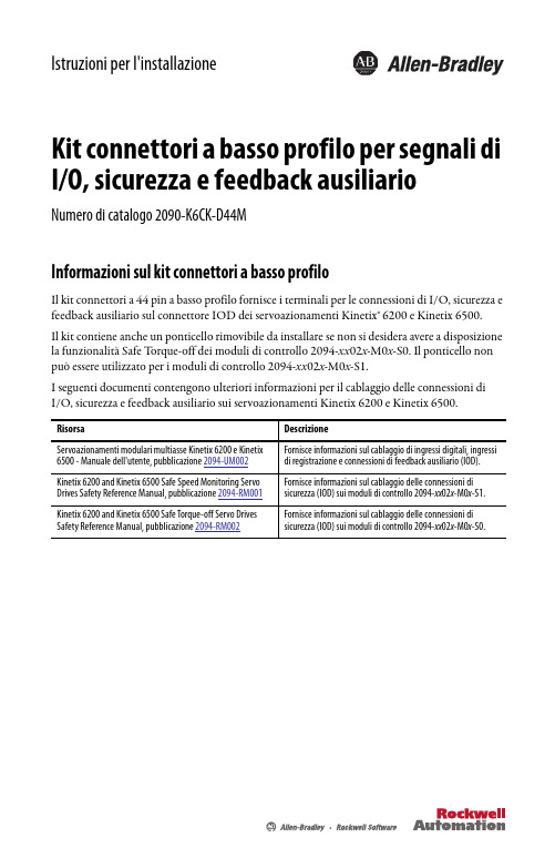
Istruzioni per l'installazioneKit connettori a basso profilo per segnali di I/O, sicurezza e feedback ausiliarioNumero di catalogo 2090-K6CK-D44MInformazioni sul kit connettori a basso profiloIl kit connettori a 44 pin a basso profilo fornisce i terminali per le connessioni di I/O, sicurezza e feedback ausiliario sul connettore IOD dei servoazionamenti Kinetix® 6200 e Kinetix 6500.Il kit contiene anche un ponticello rimovibile da installare se non si desidera avere a disposizione la funzionalità Safe T orque-off dei moduli di controllo 2094-xx02x-M0x-S0. Il ponticello non può essere utilizzato per i moduli di controllo 2094-xx02x-M0x-S1.I seguenti documenti contengono ulteriori informazioni per il cablaggio delle connessioni diI/O, sicurezza e feedback ausiliario sui servoazionamenti Kinetix 6200 e Kinetix 6500.2 Kit connettori a basso profilo per segnali di I/O, sicurezza e feedback ausiliarioRockwell Automation Pubblicazione 2090-IN021D-IT-P - Gennaio 2015Installazione del kit connettori a basso profiloATTENZIONE: Il kit connettori contiene parti sensibili alle scariche elettrostatiche (ESD), chepossono subire danneggiamenti in caso di mancato rispetto delle specifiche procedure di controllo. Se non si conoscono tali procedure, consultare Guarding Against Electrostatic Damage,pubblicazione 8000-4.5.2, o qualsiasi altro manuale utile relativo alla protezione dalle scariche elettrostatiche.1.Inserire la schermatura cavo esposta nel canale.2.Instradare i fili verso i morsetti.3.Posizionare il morsetto sopra la schermatura esposta.4.Serrare le viti impostando una coppia di 0,4N•m (3,5 lb•pollici).Se necessario, rigirare il morsetto per fissare i fili piccoli.Utilizzare morsetti (3) per massimizzare il contatto con la schermatura cavo per il collegamento a massa adalta frequenza.per ridurre le sollecitazioni.Kit connettori a basso profilo per segnali di I/O, sicurezza e feedback ausiliario 3Rockwell Automation Pubblicazione 2090-IN021D-IT-P - Gennaio 2015Dati dei connettori(1)Le denominazioni tra parentesi si riferiscono al relè di sicurezza Guardmaster® MSR57P e ai morsetti dell'opzione di sicurezza PowerFlex® serie 750.(2)Utilizzare questa sorgente per alimentare l'ingresso di sicurezza a 24 V (SPWR/SCOM). Non collegare questa sorgente a 24 V ad alcun dispositivo di sicurezza esterno. Questi pin non sono utilizzabili per i moduli di controllo 2094-xx 02x -M0x -S1.Installazione del ponticello rimovibile (solo per i moduli di controllo 2094-xx 02x -M0x -S0)La numerazione dei pin del kit corrisponde a quella del connettore IOD. Ai pin 27, 28, 39 e 40 sono assegnati più morsetti per consentire connessioni aggiuntive.Power, Control and Information Solutions HeadquartersAmeriche: Rockwell Automation, 1201 South Second Street, Milwaukee, WI 53204-2496, USA, T el: +1 414 382 2000, Fax: +1 414 382 4444Europa/Medio Oriente/Africa: Rockwell Automation NV, Pegasus Park, De Kleetlaan 12a, 1831 Diegem, Belgio, T el: +32 2 663 0600, Fax: +32 2 663 0640Asia: Rockwell Automation, Level 14, Core F, Cyberport 3, 100 Cyberport Road, Hong Kong, T el: +852 2887 4788, Fax: +852 2508 1846Italia: Rockwell Automation S.r.l., Via Gallarate 215, 20151 Milano, T el: +39 02 334471, Fax: +39 02 33447701, www.rockwellautomation.itSvizzera: Rockwell Automation AG, Via Cantonale 27, 6928 Manno, T el: 091 604 62 62, Fax: 091 604 62 64, Customer Service: T el: 0848 000 279www.rockwe l l Pubblicazione 2090-IN021D-IT-P - Gennaio 2015© 2015 Rockwell Automation, Inc. Tutti i diritti riservati. Stampata negli USA.Allen-Bradley, Guardmaster, Kinetix, PowerFlex, Rockwell Software e Rockwell Automation sono marchi commerciali di Rockwell Automation, Inc.I marchi commerciali non appartenenti a Rockwell Automation sono di proprietà delle rispettive società.Rockwell Automation pubblica le informazioni ambientali aggiornate relative al prodotto sul proprio sito Web all'indirizzo/rockwellautomation/about-us/sustainability-ethics/product-environmental-compliance.page .Dati dei connettori (continua)(1)Le denominazioni tra parentesi si riferiscono al relè di sicurezza Guardmaster MSR57P e ai morsetti dell'opzione di sicurezza per PowerFlex serie 750.(2)Utilizzare questi segnali come sorgente a 24 V CC per azionare gli ingressi digitali (50 mA massimo per ingresso).Installazione del ponticello rimovibile (solo per i moduli di controllo 2094-xx 02x -M0x -S0)La numerazione dei pin del kit corrisponde a quella del connettore IOD. Ai pin 27, 28, 39 e 40 sono assegnati più morsetti per consentire connessioni aggiuntive.。
罗克韦尔 Kinetix 6000 多轴伺服驱动器 说明书.

Kinetix 6000 多轴伺服驱动器目录号2094-ACxx-Mxx-S 、2094-BCxx-Mxx-S 、2094-AMxx-S 、2094-BMxx-S2094-ACxx-Mxx 、2094-BCxx-Mxx 、2094-AMxx 、2094-BMxx 、2094-BSP2、2094-PRF 、2094-SEPM-B24-S用户手册重要用户信息在安装、配置、操作或维护本产品之前,请仔细阅读本文档及“其他资源”部分所列文档中有关安装、配置和操作此设备的信息。
除遵守所有适用的规程、法律及标准的要求外,用户还应熟悉安装 和接线说明。
安装 、 调节 、 投入使用 、 操作 、 装配 、 拆卸和维护等活动均要求由经过适当培训的人员遵照适 用法规执行。
如果未按制造商指定的方式使用设备,则设备提供的保护功能可能会受到影响。
任何情况下,对于因使用或操作本设备造成的任何间接损失或连带损失,罗克韦尔自动化公司概不负责。
本手册中包含的示例和图表仅用于说明。
由于任何特定的安装都存在很多差异和要求,罗克韦尔 自动化对于依据这些示例和图表所进行的实际应用不承担任何责任和义务。
因使用本手册中所述的信息、电路、设备或软件而引起的相关专利问题,罗克韦尔自动化公司不负任何责任。
未经罗克韦尔自动化公司的书面许可,不得复制本手册的全部或部分内容。
在整本手册中,我们在必要的地方使用了注释,来提醒您注意相关的安全事宜。
设备表面或内部也可能贴有标签,以提供特定的预防措施。
Allen-Bradley 、CompactLogix 、ControlFLASH 、ControlLogix 、DriveExplorer 、Guardmaster 、HPK-Series 、Integrated Architecture 、Kinetix 、LDC-Series 、LDL-Series 、Logix5000、MP-Series 、RDD-Series 、Rockwell Automation 、Rockwell Software 、RSLinx 、RSLogix 、SCANport 、SoftLogix 、Studio 5000 Logix Designer 、Studio 5000 和 TL-Series 是罗克韦尔自动化公司的商标。
Kinetix MMA 异步主电机安装指南说明书
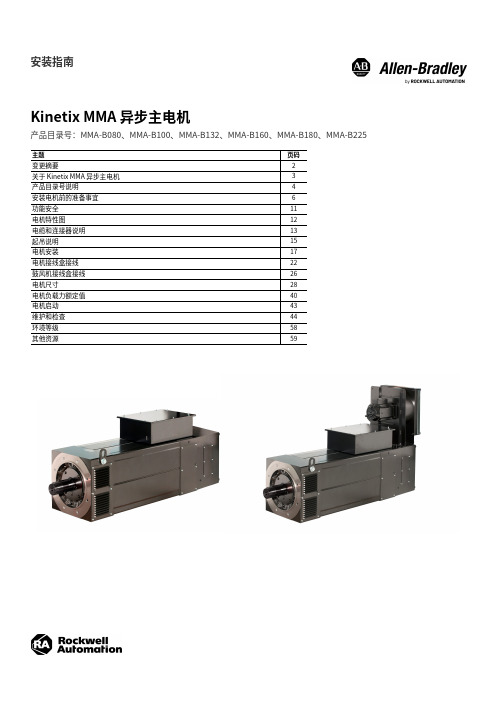
安装指南Kinetix MMA 异步主电机产品目录号:MMA-B080、MMA-B100、MMA-B132、MMA-B160、MMA-B180、MMA-B225主题⻚码变更摘要2关于 Kinetix MMA 异步主电机3产品目录号说明4安装电机前的准备事宜6功能安全11电机特性图12电缆和连接器说明13起吊说明15电机安装17电机接线盒接线22⿎⻛机接线盒接线26电机尺寸28电机负载力额定值40电机启动43维护和检查44环境等级58其他资源592罗克⻙尔⾃动化出版物 MM-IN001B-ZH-P - 2022 年2 月Kinetix MMA 异步主电机安装指南变更摘要本出版物中包含以下新增内容或更新信息。
该列表仅列出了主要更新,并未反映出所有变更。
主题⻚码将反馈连接器的运动范围从 180° 更改为 330°,但有一些例外整本手册将温度调节器 PTO 更改为 TS 整本手册更新了⿎⻛机电压技术参数整本手册更换了电机铭牌图像3更新了图1,使其包括维度 E 和重要声明7更新了图4,使其包括⿎⻛机组件和⿎⻛机外壳12安全相关参数新增了脚注 111更新了电机电源端⼦,使其包括三⻆形和星形22更新了电机负载力额定值表40更新了维护和检查,以包括所有可⽤的维护和更换步骤44…57更新了表59 以包含冲击和振动信息58本出版物中使⽤的图像是示例图像,可能不能准确代表您的电机。
罗克⻙尔⾃动化出版物 MM-IN001B-ZH-P - 2022 年2 月3Kinetix MMA 异步主电机安装指南关于 Kinetix MMA 异步主电机本手册包含有关 Kinetix® MMA 异步主电机的安装、使⽤和维护的有⽤信息。
这款交流三相电机经过优化,连接到 Kinetix 5700 和 Kinetix 7000 变频器,与 PowerFlex® 750 系列变频器兼容。
Kinetix MMA 主电机设计⽤于需要以各种速度提供最高功率和转矩输出的应⽤。
Kinetix 5100 I O 终端扩展模块安装指南说明书

Installation InstructionsOriginal InstructionsKinetix 5100 I/O Terminal Expansion BlockCatalog Number 2198-TBIOThe I/O terminal expansion block lets you wire I/O directly to the Kinetix® 5100 drive without the use of an extension cable and a separate terminal block. The I/O terminal expansion block securely mounts to the drive with its own mounting screws and simplifies I/O wiring. This publication provides installation and wiring instructions for the Kinetix 5100 I/O terminal expansion block. For further installation instructions on the Kinetix 5100 drive, refer to the Kinetix 5100 Single-axis EtherNet/IP Servo Drive User Manual, publication 2198-UM004.Before You BeginThe I/O terminal expansion block is attached to the I/O terminal on the front of the drive. When used the expansion block requires additional cabinet height and width.Front view of Kinetix 5100 drive.2198-E1004-ERS Kinetix 5100 drive is shown.Partial top view of Kinetix 5100 drive show additional clearance required for I/O terminal expansion block.PadDimensions are in mm (in.).2Rockwell Automation Publication 2198-IN020A-EN-P - August 2019Kinetix 5100 I/O Terminal Expansion BlockInstall the I/O Terminal Expansion BlockFollow these steps to install your I/O terminal expansion block.1.Wire the I/O terminal expansion block, by using the pinout table on page 3. The terminal block accepts the following.2.T o obtain a high-frequency bond between the cable shield and the expansion block and for stress relief, firmly attach the cable to the expansion block by using a tie wrap (you supply).3.Attach expansion block to the I/O connector on the front of the Kinetix 5100 drive by using a screwdriver and torque to 0.2 N•m (1.77 lb•in).Attribute 2198-TBIOWire gauge 1.5…0.05 mm 2 (16…30 AWG)Strip length 6…7 mm (0.24…0.27 in.)Torque value20 N•cm (1.77 lb•in)Tie WrapExposed copper pad is under cable shield.Route wires such that it limits stress on cable.Rockwell Automation Publication 2198-IN020A-EN-P - August 20193Kinetix 5100 I/O Terminal Expansion BlockWire the I/O Terminal Expansion BlockUse the following pinout table to wire the I/O from your system.I/O Terminal Expansion Block PinoutIOD PinDescriptionSignal1Digital output 4+OUTPUT4+2Digital output 3-OUTPUT3-3Digital output 3+OUTPUT3+4Digital output 2-OUTPUT2-5Digital output 2+OUTPUT2+6Digital output 1-OUTPUT1-7Digital output1+OUTPUT1+8Digital input 4INPUT49Digital input 1INPUT110Digital input 2INPUT211Common for digital inputs, connected to +24 or 0V DC DCOM 12Analog input signal ground AGND 13Analog input signal ground AGND 14Reserved (1)(1)The reserved pins are not present on I/O terminal expansion block.—15Analog monitor output 2AOUT216Analog monitor output 1AOUT117Reserved (1)—18Analog torque input COMMAND119Analog input signal ground AGND 20Reserved (1)—21Buffered encoder output Ch A+AMOUT+22Buffered encoder output Ch A-AMOUT-23Buffered encoder output Ch B-BMOUT-24Buffered encoder output Ch Z-ZMOUT-25Buffered encoder output Ch B+BMOUT+Allen-Bradley, Kinetix, Rockwell Automation, and Rockwell Software are trademarks of Rockwell Automation, Inc.Trademarks not belonging to Rockwell Automation are property of their respective companies.Rockwell Otomasyon Ticaret A.Ş., Kar Plaza İş Merkezi E Blok Kat:6 34752 İçerenköy, İstanbul, T el: +90 (216) 5698400Rockwell Automation maintains current product environmental information on its website at/rockwellautomation/about-us/sustainability-ethics/product-environmental-compliance.page .Publication 2198-IN020A-EN-P - August 2019Copyright © 2019 Rockwell Automation, Inc. All rights reserved. Printed in the U.S.A.Additional ResourcesThese documents contain additional information concerning related products from Rockwell Automation.Y ou can view or download publications at /global/literature-library/overview.page .Rockwell Automation SupportFor technical support, visit /support/overview.page .ResourceDescriptionKinetix Servo Drives Specifications Technical Data, publication KNX-TD003Product specifications for Kinetix Integrated Motion over the EtherNet/IP network, Integrated Motion over Sercos interface, EtherNet/IP networking, and component servo drive families.Kinetix 5100 Single-axis EtherNet/IP Servo Drive User Manual, publication 2198-UM004.Provides information on how to install, configure, start up, and troubleshoot your Kinetix 5100 servo drive system.Industrial Automation Wiring and Grounding Guidelines, publication 1770-4.1Provides general guidelines for installing a Rockwell Automation industrial system.Product Certifications website: rok.auto/certificationsProvides declarations of conformity, certificates, and other certification details.。
Kinetix 5300 单轴 EtherNet IP 伺服驱动器安装指南说明书
Kinetix 5300 单轴 EtherNet/IP 伺服驱动器产品目录号 2198-C1004-ERS 、2198-C1007-ERS 、2198-C1015-ERS 、2198-C1020-ERS 、2198-C2030-ERS 、2198-C2055-ERS 、2198-C2075-ERS 、2198-C4004-ERS 、2198-C4007-ERS 、2198-C4015-ERS 、2198-C4020-ERS 、2198-C4030-ERS 、2198-C4055-ERS 、2198-C4075-ERS关于Kinetix 5300驱动器Kinetix 5300 伺服驱动器针对连续三相输出功率和电流需求分别为 0.72…14.7 kW 和 2.3…67.5A 0-pk-峰值的应用项目提供了基于EtherNet/IP 网络的集成运动控制解决方案。
有关接线、上电、故障处理以及与 ControlLogix®5570、ControlLogix 5580、CompactLogix™ 5370 或 CompactLogix 5380 控制器和 Studio 5000Logix Designer® 应用程序集成的详细信息,请参见 Kinetix 5300 Servo Drives User Manual ,出版号 2198-UM005。
产品目录号说明本安装指南适用于以下 Kinetix 5300 伺服驱动器。
主题页码关于Kinetix 5300驱动器1准备事宜2安装Kinetix 5300驱动器2连接器数据4接线要求6安装电机电缆屏蔽夹8断路器/熔断器选择9电机过载保护11其他资源11Kinetix 5300 驱动器产品目录号目录 号框架尺寸输入电压(1)(1)需要使用标称输入电压额定值(110、230 或 480V rms )来提供充足的电源。
连续输出功率kW连续输出电流A (rms)连续输出电流A (0-峰值)2198-C1004-ERS185…132V rms 单相 170…253V rms 单相170…253V rms 三相0.220.460.722.84.02198-C1007-ERS 10.360.761.18 4.6 6.52198-C1015-ERS 20.671.412.188.512.02198-C1020-ERS 20.972.023.1312.217.32198-C2030-ERS 2170…253V rms 三相5.0219.627.72198-C2055-ERS 310.3040.256.92198-C2075-ERS 312.2247.767.52198-C4004-ERS 1342…528V rms 三相0.86 1.6 2.32198-C4007-ERS 1 1.55 2.9 4.12198-C4015-ERS 2 2.785.27.42198-C4020-ERS 2 3.907.310.32198-C4030-ERS 26.2511.716.52198-C4055-ERS 312.0822.632.02198-C4075-ERS314.7027.538.9拆除组件内部和周围的所有包装材料、楔形物和支撑架。
Kinetix 5500 交流线路滤波器安装指南

资源 《Kinetix 5500 伺服驱动器用户手册》, 出版号 2198-UM001 《电噪声控制系统设计参考手册》, 出版号 GMC-RM001 《EMC 噪声管理 DVD 光盘》,出版号 GMC-SP004
《工业自动化布线和接地指南》,出版号 1770-4.1
产品认证网站:
ዐ࿔ྪ ႎષྲձ /rockwellchina
ெዞں൶ǖஆਖ਼ྴܻጲࣅۯLjళܾٷন1201ࡽLjܻएLjdzl 53204-2496 ெࡔLjࣆۉǖ(1) 414.382.2000Ljدኈǖ(1) 414.382.4444 ౹ዞ/ዐ۫/ݥዞǖஆਖ਼ྴܻጲࣅۯLjVorstlaan/Boulevard du souverain 36. 1170քܻLjԲ૧้Ljࣆۉǖ(32) 2 663 0600, دኈǖ(32) 2 663 0640 ჱں൶ǖஆਖ਼ྴܻጲࣅۯLjၑߗຕஓߗڢ100ࡽຕஓߗ3ፗF൶14୍1401-1403 ࣆۉǖ(852)2887 4788 دኈǖ(852)2508 1486 ዐࡔጺևǖฉ࡛Ⴘࣹ൶࢟ୟ1801ࡽࢢᄽٷေ ᆰՊǖ200233 ࣆۉǖ(86 21)6128 8888 دኈǖ(86 21)6128 8899
55
227
(2.16)
(8.94)
交流线路滤波器尺寸 (目录号 2198-DB42-F)
258 (10.16)
60 (2.36)
R3.3
(0.13)
9.5
(0.37)
尺寸单位为 mm (in.)。 240 (9.45)
162 (6.38)
1.2 (0.05)
73 (2.87)
272 (10.71)
Ø 6.0 (0.24) 42 (1.65)
步科Kinco 低压伺服驱动器使用手册
第 2 章 系统安装要求与注意事项.................................................................................................................................4
2.1 驱动器安装.......................................................................................................................................................... 4 2.1.1 安装尺寸..................................................................................................................................................... 4
第 1 章 系统配置和型号说明.........................................................................................................................................1
请确认驱动器各种端子是否齐全,以及电机油封和键是否齐全。
产品外观是否有损伤?
请确认产品是否在运输过程中有损坏。
如以上任一项有问题,请与本公司或您的供货商联系解决。
o 低压伺服驱动器使用手册
目录
目录
前言 产品确认.................................................................................................................................................................0
伺服驱动器外部接线与详细说明
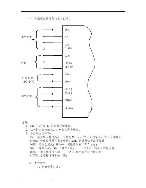
一、伺服驱动器外部接线及说明。
SRV-CTRLPLC外部电源(DC 24V)SRV-CTRL说明:1、SRV-CTRL指PLC的伺服控制模块;2、以→指向者为输入,以←指向者为输出。
3、各信号含义如下:INH: 禁止输入脉冲指令(开路时禁止);OZ-: Z相输出;OZ+: Z相输出;S-RDY: 伺服驱动器已准备就绪;ALM: 伺服驱动器故障报警;COIN: 定位已完成;SRV-ON: 伺服驱动器“开”信号;COM-: 电源负极;COM+: 电源正极; PULS1: 指令脉冲输入端;PULS2: 指令脉冲输入端; SIGN1: 指令脉冲符号输入端;SIGN2: 指令脉冲符号输入端;二、参数说明:1、参数设置方法。
操作面板上共有5个按键,意义如下:MODE:模式转换键,按此键可在4个模式间切换,这4个模式是:DP-××××: 选择监视项目(共有7个, 在按 MODE键显示DP-××××后先按SET,再按↑或↓选择)⑴、DP-EPS: 位置偏差;⑵、DP-SPD: 转速;⑶、DP-TRQ: 转矩;⑷、DP-CNT: 控制方式;⑸、DP-IO: 输入输出信号状态;⑹、DP-ERR: 错误信息;⑺、DP_NO: PR-××××: 设定参数。
EE-××××: 写入参数。
AT-××××: 自动增益调整。
SET:为设定及确认键。
↑:数值增加或移动到下一个选项;↓:数值减少或移动到上一个选项;←:数位间移动;具体设置步骤详见有关Driver的补充信息说明:1、参数后加“#“者为需要更改的,如02号参数实际应用中应设为0;2、控制方式含义T:转矩控制S:速度控制P:位置控制3、出厂设定为”*”者为出厂时未设置,需根据实际自行设置;4、其余参数可使用出厂设置;5、最后一栏为新Driver与之对应的参数(有些没有);6、更详细的说明参见Driver手册(旧)或参考Driver手册(新)中对应的参数;7、以下表格为Driver实际参数设置表。
Kinetix5500伺服驱动器和VP低惯量电机专题培训课件
可满足您需求的单电缆运动控制系统
Copyright © 2012 Rockwell Automation, Inc. All rights reserved. 1
单电缆运动控制解决方案概览
Kinetix VPL 伺服电机
Kinetix 5500 伺服驱动器
Kinetix 5500 伺服驱动器
开环频率控制方法
Kinetix 5500 驱动器支持“两种”开环频率控制方法 • 基本 V/Hz • 带滑差补偿的无传感器矢量控制方法,支持更强的速度调节能力
Kinetix 5500 驱动器的开环频率控制适合不需要飞速启动功能的传送带、 泵和风机等应用
• 支持静态升压、运转升压和自动升压功能 • 电子式电机热过载保护,符合 10 类要求 • 可在带间跳跃
支持适合变频器运行的第三方三相感应电机。
最大输出频率:400Hz(电气) 最大极对数: 50 最大电机电缆长度:50 米
Copyright © 2012 Rockwell Automation, Inc. All rights reserved. 9
Kinetix 5500 伺服驱动器
相对定位
价 格
Copyright © 2012 Rockwell Automation, Inc. All rights reserved. 4
Kinetix 5500 伺服驱动器
于更小的外形下提供一流的功率密度
Copyright © 2012 Rockwell Automation, Inc. All rights reserved.
灵活的电源连接方式
设计用于多种电源拓扑,不降低解决方案的任何性能。Kinetix 5500 可用于多轴 应用,享交流/直流电源或直流母线的驱动器组成。
KINETROLEL电气定位器安装操作维护说明

KINETROL EL电气定位器安装操作维护说明1、目录页码章节11-目录22-安装22-0简介22-1在调节器直接安装部分2 2-2安装不连续远程位置调节器2 2-3空气和电力连接2 2-3-1空气供应3 2-3-2DIN插头选择3 2-3-3远程位置调节器信号4 3-功能示意图表4 4-安装34-0介绍5 4-1设置行程速度5 4-2设置限位开关凸轮5 4-3概述—电气设置5 4-4默认设置和重设程序6 4-5进入与退出安装模式6 4-6自动结束搜索程序6-7 4-7比例增加与衰减设置7-8 4-8低电流点与高电流点设置8 4-9远程位置调节器的顺时针和逆时针回动8-9 4-10弱信号运行时方向的改变9 4-11重设反馈罐9 4-12电可擦除只读存储器求校错误9-10 4-13选择设计非线性曲线图表10 4-14设置可选跨距与调零11 4-15可选底胶位监视器位置的调节12 5-维护及故障的清除2-安装2-0介绍远程位置调节器可以用来直接安装或者准备直接安装,在转动装置上或者单独在架子上通过一些90度旋转装置来安装。
如果此远程位置调节器在执行器上准备安装,2.1和2.2章可被忽略。
2.1在调节器直接安装部分移动执行器叶片到中间运行位置使输出量如图1所示,这是防止在确定方向上出现并发问题的根本。
移动调节器的封盖,松开五个M4 槽沟顶部的螺丝保持红色塑胶输送盘在机体内。
拆开连到伺服阀上的两根金属丝,用轴等抬起整个输送盘装配。
在如图1所示的方向上将调节器机体闩紧到执行器上,要注意使O型圈在执行器出口密封的位置上。
并使执行器的轴位于孔的正中心位置。
对于07和大的样式,在执行器角落上方按图2所示逆向反斜线安装弹簧。
观测可到达调节器轴的范围,受信号区轮子分压计的正确运行方向限制,由不锈钢带驱动(见图3).用中间范围附近的轴将输送盘/轴装配回调节器盒,在维修它的位置在中间范围附近时,“感应”一下执行器上的调节器。
Kinetix 5500 伺服驅動器使用手冊说明书

Kinetix 5500 伺服驅動器型號 2198-H003-ERS、2198-H008-ERS、2198-H015-ERS、2198-H025-ERS、2198-H040-ERS、2198-H070-ERS、2198-H003-ERS2、2198-H008-ERS2、2198-H015-ERS2、2198-H025-ERS2、2198-H040-ERS2、2198-H070-ERS2、2198-CAPMOD-1300本手冊連結至 Kinetix 5500 伺服驅動器故障碼參考資料,出版物2198-RD005,以供故障碼查詢。
立即下載試算表以離線存取。
2Rockwell Automation 出版品 2198-UM001L-ZC-P - 2022 年 2 月Kinetix 5500 伺服驅動器使用手冊使用者重要資訊進⾏本產品的安裝、設定、操作或維護前,請閱讀本文件及其他資源一節內有關本設備安裝、設定和操作的文件。
使用者除了必須瞭解所有相關法規、法律條文與標準外,還需熟知安裝與配線說明。
舉凡安裝、調整、運作、使用、組裝、拆卸及維護等作業,均需由受訓合格的⼈員依照相關法規進⾏。
若以製造商未提及之方式使用本設備,將可能損害到製造商為本設備所提供的保護措施。
不論任何情況,Rockwell Automation Inc. 對於使用或應用此裝置而產生的間接或連帶損壞,均不負擔任何法律或賠償責任。
本手冊中的範例和圖表皆僅供說明之用。
由於個別安裝會有許多不同的變數及條件,Rockwell Automation,Inc. 無法對依照範例及圖⽰指⽰進⾏的實際使用狀況負責或提供賠償。
關於本手冊中所述之資訊、電路、設備或軟體部分,Rockwell Automation Inc. 概不承擔任何專利責任。
在取得 Rockwell Automation Inc. 書面同意之前,禁止重製本手冊部分或全部內容。
在整本手冊中,我們會在必要時使用註記,讓您瞭解安全注意事項。
雷赛L5系列使用手册v1(1)
小心
ii
前 言
接线必须正确而且牢固,否则可能会使伺服电机错误运转,也可能因 接触不良损坏设备。 伺服电机 U、V、W 端子不可反接,不可接交流电源。 伺服电机与伺服驱动器之间须直连,不能接入电容、电感或滤波器。 防止导电紧固件及电线头进入伺服驱动器。 电线及不耐温体不可贴近伺服驱动器散热器和伺服电机。 并接在输出信号直流继电器上的续流二极管不可接反。
i
前 言
不得拖曳电线、电机轴和编码器搬运伺服电机。 伺服驱动器及伺服电机不得承受外力及撞击。
安装
小心
伺服驱动器和伺服电机: 伺服驱动器和伺服电机:
不得安装在易燃品上面或附近,防止火灾。 避免振动,严禁承受冲击。 受损或零件不全时,不得进行安装。
伺服驱动器: 伺服驱动器:
必须安装在足够防护等级的控制柜内。 必须与其它设备间保留足够的间隙。 必须有良好的散热条件。 防止尘、腐蚀性气体、导电物体、液体及易燃易爆物质侵入。
安全守则
警告
本产品的设计和制造并非是为了使用在对人身安全有威胁的机械和 系统中。 用户的机械和系统选用本产品时,须在设计和制造中考虑安全防护措 施,防止因不当操作或本产品异常意外事故。
验收
小心
损坏或有故障的产品不可投入使用。
运输
小心
必须按产品储运环境条件储存和运输。 不得超高堆放,防止跌落。 转运时产品应包装妥善。
阅读本手册时,请特别留意以下警示标志:
警告 小心 注意
表示错误的操作可能会引起灾难性的后果—— 表示错误的操作可能会引起灾难性的后果——死亡或重伤 ——死亡或重伤。 死亡或重伤。
表示错误的操作可能使操作人员受到伤害, 表示错误的操作可能使操作人员受到伤害,还可能使设备损坏。 还可能使设备损坏。
Kinetix 5500 电容器模块安装说明

2198-CAPMOD-1300 电容器模块 ( 侧视图 )
表8-
1
编织接地线
2
25.4 mm (1.0 in.) x 6.35 mm
2198-CAPMOD-1300 电容 器模块
( 正视图 )
4
24V 控制输入电源 (CP) 连接器
(1) 直流母线连接器随附保护性触碰器盖,在共 享母线配置中使用时可将其拆除。
6 Kinetix 5500 电容器模块
表 4 - 直流母线 (DC) 连接器引脚
直流引脚 1 2
说明 直流母线连接端
表 5 - 控制输入电源 (CP) 连接器引脚
电击危险:为避免电击危险,请在完成 Kinetix 5500 伺服驱动器的 所有安装和接线作业之后再上电。一旦上电,即使不使用,连接器 端子也可能带电压。
注意:规划系统安装,以便在将系统从机壳中取出后执行所有切 割、钻孔、攻丝、焊接工作。由于系统采用开放式结构,请小心操 作,避免金属碎屑进入系统。金属碎屑或其他异物可能卡在电路 中,造成元件损坏。
新产品退货
在所有产品出厂前,罗克韦尔自动化公司都会进行测试,以确保产品完全可用。但是,如 果您的产品无法正常工作需要退货,请遵循下列步骤。
美国
请联系您的分销商。必须向经销商提供客户支持案例号码 (可拨打 以上电话号码获取)以完成退货流程。
表 7 - 电容器模块接线要求
连接器说明 引脚
模块状态指示 灯
PELV/SELV 24V 电源
Kinetix 5100 AC Line Filter 安装指南说明书
Installation InstructionsOriginal InstructionsKinetix 5100 AC Line FilterCatalog Numbers 2198-DB111-F, 2198-DB127-F, 2198-DB310-F, 2198-DB324-F, 2198-DB335-F, 2198-DB356-F, 2198-DB418-F, 2198-DB433-FThis publication provides installation instructions for the AC line filters used with Kinetix® 5100 servo drives. Use these instructions for installing and wiring your AC line filter. For more information on installing and wiring your AC line filter, see Kinetix 5100 Single-axis EtherNet/IP™ Servo Drives Users Manual, publication 2198-UM004.Summary of ChangesThis publication contains the following new or updated information. This list includes substantive updates only and is not intended to reflect all changes.Topic Page Summary of Changes 1Before You Begin 2Install the AC Line Filter 2AC Line Filter Dimensions 3AC Line Filter Specifications 6Additional Resources6Topic Page Updated dimension on three-phase leads to 600 mm (23.62 in) for: 2198-DB310-F, 2198-DB324-F, 2198-DB418-F, 2198-DB335-F, and 2198-DB433-F. 3…5Updated AC Line Filter Specifications table.62Rockwell Automation Publication 2198-IN017D-EN-P - June 2021Kinetix 5100 AC Line Filter Installation InstructionsBefore You BeginFor general guidelines when laying out your panel and mounting your AC line filter, refer to the System Design for Control of Electrical Noise Reference Manual, publication GMC-RM001.For guidelines specific to your application, refer to the Kinetix 5100 Single-axis EtherNet/IP Servo Drives Users Manual, publication 2198-UM004.Install the AC Line FilterMount the line filter to the cabinet panel with hardware as specified in this table.See the System Design for Control of Electrical Noise Reference Manual, publication GMC-RM001, for techniques on how to make proper high-frequency (HF) bonds to improve overall system performance.For wiring guidelines specific to your application, see the Kinetix 5100 Single-axis EtherNet/IP Servo Drives User Manual, publication 2198-UM004.ATTENTION: To avoid personal injury or damage to equipment due to hazardous voltages, follow these guidelines when installing your AC line filter. NEC and local regulations always take precedence.•Disconnect mains power before installation.•Verify that the rated voltage is compatible with the local supply voltage.•Connect the earth ground connection first when you make connections.Cat. No. Mounting BoltTorque Value N•m (lb•in)Mounting Bolt (1)(for piggybackmounting of the drive)(1)Piggyback mounting of the drive to the line filter is available only for 2198-DB418-F and hardware Rev 1.1 or later of 2198-DB111-F,2198-DB127-F, 2198-DB310-F, and 2198-DB324-F.Torque Value (1)N•m (lb•in)2198-DB111-F M5 (#10-24)1.6…2.0 (13.9…17.70)M5 (#10-24)1.6…2.0 (13.9…17.70)2198-DB127-F 2198-DB310-F 2198-DB324-F 2198-DB335-F ——2198-DB356-F ——2198-DB418-F M5 (#10-24) 1.6…2.0 (13.9…17.70)2198-DB433-F——Rockwell Automation Publication 2198-IN017D-EN-P - June 20213Kinetix 5100 AC Line Filter Installation InstructionsAC Line Filter DimensionsFor line filter dimensions specific to your application, see the Kinetix Servo Drives Specifications Technical Data, publication KNX-TD003.AC Line Filter Dimensions (Catalog number 2198-DB111-F)AC Line Filter Dimensions (Catalog number 2198-DB310-F)30.023.020.0(Minimum)30.023.020.0(Minimum)4Rockwell Automation Publication 2198-IN017D-EN-P - June 2021Kinetix 5100 AC Line Filter Installation Instructions AC Line Filter Dimensions (Catalog numbers 2198-DB127-F)AC Line Filter Dimensions (Catalog numbers 2198-DB324-F and 2198-DB418-F)29.128.029.128.0Rockwell Automation Publication 2198-IN017D-EN-P - June 20215Kinetix 5100 AC Line Filter Installation InstructionsAC Line Filter Dimensions (Catalog numbers 2198-DB335-F and 2198-DB433-F)AC Line Filter Dimensions (Catalog number 2198-DB356-F)33.028.0(Minimum)(0.22)28.0(1.10)33.0(1.30)Dimensions are in mm (in.).6Rockwell Automation Publication 2198-IN017D-EN-P - June 2021Kinetix 5100 AC Line Filter Installation InstructionsAC Line Filter SpecificationsFor more information about AC line filters, see AC Line Filters Installation Instructions, publication 2198-IN003.Additional ResourcesThese documents contain additional information concerning related products from Rockwell Automation.You can view or download publications at rok.auto/literature .Cat. No.Voltage Rating (1)(1)SCCR Rating of 5kA when used with UL branch circuit protection as listed in Kinetix 5100 EtherNet/IP Indexing Servo Drives,publication 2198-UM004.Current Rating A @ 50 °C (122 °F)Power Loss WLeakageCurrent mA, typicalWeight, approxkg (lb)Operating Temperature(Surrounding Air, max.)2198-DB111-F 120V s ingle-phase, 50/60 Hz200…230V single-phase, 50/60 HZ 11 4.952.9 1.05 (2.314)50 °C (122 °F)2198-DB127-F 2715.554.91.80 (3.968)2198-DB310-F 120V s ingle-phase, 50/60 Hz200…230V single-phase, 50/60 HZ 10 4.737.4 1.10 (2.425)2198-DB324-F 249.7901.95 (3.968)2198-DB310-F 200...240V AC, three-phase,50/60 Hz1014.0 3.9 1.10 (2.425)2198-DB324-F 2429.09.3 1.95 (3.968)2198-DB335-F 240V AC, three-phase,48...63 Hz34.830.0 5.8 2.90 (6.393)2198-DB356-F 5657.0 2.8 4.00 (8.818)2198-DB418-F 480V AC three-phase,48…63 Hz 18.416.0 4.21 1.20 (2.65)2198-DB433-F3335.0 3.58 1.90 (4.19)ResourceDescriptionKinetix Servo Drives Specifications Technical Data, publication KNX-TD003Provides product specifications for the Kinetix Integrated Motion over EtherNet/IP network, Integrated Motion over Sercos interface, EtherNet/IP networking, and component servo drive families.Kinetix Motion Accessories Specifications Technical Data, publication KNX-TD004Provides product specifications for Bulletin 2090 motor and interface cables, low-profile connector kits, drive power components, and other servo drive accessory items.AC Line Filters Installation Instructions, publication 2198-IN003Provides information on how to install and wire AC line filters used with the Kinetix 5500 and Kinetix 5700 servo drive systems and the Kinetix 5700 iTRAK® power supply.Kinetix 5100 Single-axis EtherNet/IP Servo Drives Users Manual, publication 2198-UM004Information on how to install, configure, start, and troubleshoot your Kinetix 5100 servo drive system.Servo Drive Installation Best Practices Application Technique, publication MOTION-AT004Provides best practice examples to help reduce the number of potential noise or electromagnetic interference (EMI) sources in your system and to make sure that the noise-sensitive components are not affected by the remaining noise.Industrial Automation Wiring and Grounding Guidelines, publication 1770-4.1 Provides general guidelines for installing a Rockwell Automation industrial system.Product Certifications website: rok.auto/certificationsProvides declarations of conformity, certificates, and other certification details.Kinetix 5100 AC Line Filter Installation Instructions Notes:Rockwell Automation Publication 2198-IN017D-EN-P - June 20217Publication 2198-IN017D-EN-P - June 2021 | Supersedes Publication 2198-IN017C-EN-P - August 2020Copyright © 2021 Rockwell Automation, Inc. All rights reserved.Rockwell Otomasyon Ticaret A.Ş. Kar Plazaİş Merkezi E Blok Kat:6 34752, İçerenköy, İstanbul, Tel: +90 (216) 5698400 EEE Yönetmeli ğine UygundurAllen-Bradley, expanding human possibility, FactoryTalk, iTRAK, Kinetix, and Rockwell Automation are trademarks of Rockwell Automation,Inc.EtherNet/IP is a trademark of ODVA, IncTrademarks not belonging to Rockwell Automation are property of their respective companies.Your comments help us serve your documentation needs better. If you have any suggestions on how to improve our content, complete the form at rok.auto/docfeedback.Waste Electrical and Electronic Equipment (WEEE)Rockwell Automation maintains current product environmental compliance information on its website at rok.auto/pec .At the end of life, this equipment should be collected separately from any unsorted municipal waste.Rockwell Automation SupportUse these resources to access support information.Technical Support Center Find help with how-to videos, FAQs, chat, user forums, andproduct notification updates.rok.auto/support KnowledgebaseAccess Knowledgebase articles.rok.auto/knowledgebase Local Technical Support Phone Numbers Locate the telephone number for your country.rok.auto/phonesupport Literature LibraryFind installation instructions, manuals, brochures, andtechnical data publications.rok.auto/literature Product Compatibility and Download Center (PCDC)Download firmware, associated files (such as AOP, EDS, and DTM), and access product release notes.rok.auto/pcdc。
罗克韦尔 Kinetix 6200 和 Kinetix 6500 自定义多轴服务器驱动器 说明书.

Kinetix 6200 和 Kinetix 6500 模块化多轴伺服驱动器目录号 2094-BCxx-Mxx-M, 2094-BMxx-M 2094-SE02F-M00-Sx, 2094-EN02D-M01-Sx,2094-BSP2, 2094-PRF, 2094-SEPM-B24-S用户手册用户重要须知在安装、配置、操作或维护本产品之前,请阅读本文档以及“其他资源”章节所列的文档,了解关于安装、配置和操作该设备的信息。
除了所有适用的条例、法律和标准的要求之外,用户还必须熟悉安装和接线说明。
包括安装、调整、投入运行、使用、装配、拆卸和维护等在内操作必须由经过适当培训的人员根据适用的操作守则来执行。
如果未遵照制造商所指定的方式使用该设备,将可能导致该设备提供的保护失效。
任何情况下,对于因使用或操作本设备造成的任何间接或连带损失,罗克韦尔自动化有限公司概不负责。
本手册中包含的示例和图表仅用于说明。
由于任何具体安装都涉及众多变数和要求,罗克韦尔自动化有限公司对于依据这些示例和图表所进行的实际应用不承担任何责任和义务。
对于因使用本手册中所述信息、电路、设备或软件而引起的专利问题,罗克韦尔自动化有限公司不承担任何责任。
未经罗克韦尔自动化有限公司的书面许可,不得复制本手册的全部或部分内容。
在整本手册中,我们在必要的地方使用了以下注释,以提醒您注意相关的安全事宜。
标签可能位于设备表面或内部,以提供特定警示。
警告:标识在危险环境下可能导致爆炸,进而导致人员伤亡、物品损坏或经济损失的操作或情况。
注意:标识可能导致人员伤亡、物品损坏或经济损失的操作或情况。
注意符号可帮助您确定危险情况,避免发生危险,并了解可能的后果。
重要信息标识对成功应用和了解本产品有重要作用的信息。
触电危险:位于设备 (例如,驱动器或电机) 表面或内部的标签,提醒相关人员可能存在危险电压。
灼伤危险:位于设备 (例如,驱动器或电机) 表面或内部的标签,提醒相关人员表面可能存在高温危险。
Kinetix VPC 连续重载伺服电机产品安装说明书

安装说明电机框架尺寸为 165 mm 、215 mm 和 300 mm 的 Kinetix VPC 连续重载伺服电机产品目录号 VPC-B1652A 、VPC-B1653A 、VPC-B1652D 、VPC-B1653D 、VPC-B1654D 、VPC-B21539、VPC-B21549、VPC-B2153A 、VPC-B2154A 、VPC-B2154B 、VPC-B2154D 、VPC-B2155B 、VPC-B2155D 、VPC-B2156A 、VPC-B2156D 、VPC-B30029、VPC-B30039、VPC-B30049、VPC-B3002A 、VPC-B3003A 、VPC-B3004A 、VPC-B3004B 、VPC-B3004D变更摘要本出版物中包含新增和更新信息,如下表所述。
主题 页码变更摘要1关于Kinetix VPC 连续重载电机2产品目录号说明2安装电机前的准备事宜3功能安全5电机安装6VPC-B165xx 、VPC-B215xx 和 VPC-B300xx 的电机尺寸(单连接器)9VPC-B165xx 、VPC-B215xx 和 VPC-B300xx 的电机尺寸(电机电源/反馈连接器)11连接器数据14电机负载力额定值15环境防护等级282090 系列电机电缆28轴密封套件28附加资源29主题页码将不带风扇的 Kinetix VPC 电机(A 选项)添加到现有产品目录号和尺寸中。
2, 9…13添加产品目录号 VPC-B2154B 、VPC-B2155B 、VPC-B2156A 和 VPC-B3004B (无风扇选项的电机)。
添加带多圈绝对值编码器的 VPC-B3004x -M 伺服电机(Hiperface 协议)。
2添加升吊说明。
3更新功能安全认证信息。
52罗克韦尔自动化出版物 VPC-IN001C-ZH-P- 2020年2月电机框架尺寸为 165 mm 、215 mm 和 300 mm 的 Kinetix VPC 连续重载伺服电机关于Kinetix VPC 连续重载电机Kinetix® VPC 伺服电机采用单圈或多圈高分辨率绝对值编码器,提供附带或不附带 24V 直流制动器的型号。
Kinetix 5500 伺服驱动器安装指南
输入电压
195…264V rms,单相 195…264V rms,三相 324…528V rms,三相
195…264V rms,三相 324…528V rms,三相
连续 输出功率 kW
0.2 kW 0.3 kW 0.6 kW
0.5 kW 0.8 kW 1.6 kW
1.0 kW 1.5 KW 3.2 kW
拆除不接地电源配置中的接地螺丝
仅在使用不接地或角接地的电源配置时才需要拆除接地螺丝。拆除螺丝涉及获取权 限、打开侧门以及拆除这几个步骤。
重要信息 如果采用经过接地的 Y 型配电系统,则不必拆除螺丝。转到第 5 页的安装 Kinetix 5500 伺服驱动器。 拆除接地螺丝可能会影响 EMC 性能。
若要拆除多轴配置中的接地螺丝,最好的方法是从面板上拆下驱动器,然后将其侧 放在一个布置为接地防静电工作站的坚实表面来进行拆除。
安装指南
Kinetix 5500 伺服驱动器
产品目录号 2198-H003-ERS、2198-H008-ERS、2198-H015-ERS、 2198-H025-ERS、2198-H040-ERS、2198-H070-ERS、2198-H003-ERS2、 2198-H008-ERS2、2198-H015-ERS2、2198-H025-ERS2、2198-H040-ERS2、 2198-H070-ERS2
2.4 kW 5.1 kW
4.0 kW 8.3 kW
7.0 kW 14.6 kW
连续 输出电流 A 0-峰值 1.4
3.5
7.1
11.3 18.4 32.5
准备工作
拆除组件内部和周围的所有包装材料、楔形物和支撑架。拆开包装后,请对照订购 单检查货物铭牌目录号。
Kinetix 5500 伺服驱动器和 VP 低惯量电机资料

Kinetix VPL 电机
绕组速度的优势
▪ 绕组为匹配 Kinetix 5500 驱动器而优化 ▪ 可根据应用需求最大程度地降低轴成本 ▪ 提高机器效率
电机绕组 #1
电机绕组 #2
电机绕组 #3
6000 rpm 6.5 N-m
16 A 8.7 kW 驱动器 14 AWG 电缆
3000 rpm 6.5 N-m
可满足您需求的单电缆运动控制系统
Copyright © 2012 Rockwell Automation, Inc. All rights reserved. 2
单电缆运动控制解决方案概览
Kinetix VPL 伺服电机
Kinetix 5500 伺服驱动器
框架 165
框架 130 框架 115 框架 100
单电缆运动控制解决方案:
Kinetix 5500 伺服驱动器和 VP 低惯量电机
2012 年 10 月 11 日
Rev 5058-CO900C
Copyright © 2012 Rockwell Automation, Inc. All rights reserved.
Kinetix 5500 伺服驱动器和 VPL 电机
电压额定值和产品目录号
输入 电压
输入 相数
连续 电流 (RMS)
195-528
1/3phase
1
195-528
1/3phase
2.5
195-528
1/3phase
5
195-528
3phase
8.4
195-528
3phase
13
195-528
3phase
23
1
峰值 电流 (RMS) 2.5
Allen-Bradley Kinetix TLC 紧凑型伺服电机 安装说明说明书
安装说明Kinetix TLC 紧凑型伺服电机产品目录号 TLC-A046010、TLC-A070020、TLC-A070040、TLC-A090075关于 Kinetix TLC 伺服电机Kinetix® TLC 紧凑型伺服电机通过 Kinetix 5100 伺服驱动器的最佳性能测试和验证,并具有可选的 24V DC 抱闸。
从货运公司收到货物时,客⼾负责查验设备。
对照订单检查收到的物品。
如有任何运输损坏或物品丢失,请立即通知承运商。
应在第2 ⻚的环境技术参数中指定的洁净、干燥地点存放或操作电机。
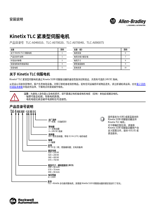
产品目录号说明主题⻚码主题(续)⻚码关于 Kinetix TLC 伺服电机 1 电机安装 6 产品目录号说明 1 电机负载力额定值7 环境技术参数2电机尺寸8 安装电机前的准备事宜 3 转矩速度曲线9安装电缆5其他资源10注意:为避免人身伤害以及电机损坏,请不要通过电机轴或电机电缆(如有)来抬起或搬动电机。
•轴罩可能会松脱,导致电机跌落。
•电机电缆拉紧会破坏电源和信号连接性。
出厂选件A = 标准(无轴密封)制动器2 = 无制动器4 = 24V DC 抱闸轴键J = 轴键连接器A3 = 矩形连接器,带有 0.3 m (1 ft.) 电机电缆额定功率 010 = 100 W 020 = 200 W 040 = 400 W 075 = 750 W框架尺寸 – 螺栓圆直径 (BCD)046 = 46 mm 070 = 70 mm 090 = 90 mm 电压等级A = 200V系列TLC = Kinetix 多功能伺服电机,其根据 Kinetix 5100 伺服驱动器的额定值进⾏了优化。
反馈N= 22 位/转;增量编码器;无电池备⽤TLC -A xxx xxx - x x xx x x固件版本为 4.001 或更⾼版本的 Kinetix 5100 伺服驱动器支持 Kinetix TLC 电机。
对于精确匹配应⽤,请使⽤ Kinetix 5100 伺服驱动器⽤⼾⾃定义配置文件,版本 4.01.01 或更⾼版本。
- 1、下载文档前请自行甄别文档内容的完整性,平台不提供额外的编辑、内容补充、找答案等附加服务。
- 2、"仅部分预览"的文档,不可在线预览部分如存在完整性等问题,可反馈申请退款(可完整预览的文档不适用该条件!)。
- 3、如文档侵犯您的权益,请联系客服反馈,我们会尽快为您处理(人工客服工作时间:9:00-18:30)。
注意:确认可能造成人身伤害或死亡、财产损坏或经济损失的行为或情况的信 息。“注意”信息帮助您识别危险情况,避免发生危险,并了解可能的后果。
重要信息 标识信息,用来标识成功应用和理解产品的关键信息。
标签可能位于设备表面或内部,以提供特定警示。
安装指南
Kinetix 5500 伺服驱动器
产品目录号 2198-H003-ERS、2198-H008-ERS、2198-H015-ERS、 2198-H025-ERS、2198-H040-ERS、2198-H070-ERS、2198-H003-ERS2、 2198-H008-ERS2、2198-H015-ERS2、2198-H025-ERS2、2198-H040-ERS2、 2198-H070-ERS2
埋入式锁销与 开口对齐
母线公用配置中使用的母排 系统的简单示意图。
2. 用 M4 (#8-32) 钢制机螺丝将 Kinetix 5500 驱动器安装到机柜子面板上,螺丝 的最大紧固扭矩为 2.0 N•m (17.7 lb•in)。
罗克韦尔自动化 出版物 2198-IN001C-ZH-P - 2014 年 1 月
罗克韦尔自动化 出版物 2198-IN001C-ZH-P - 2014 年 1 月
Kinetix 5500 伺服驱动器 3
产品目录号说明
本安装指南适用于以下 Kinetix 5500 伺服驱动器。为连接安全断开扭矩信号,硬接 线驱动器将使用安全断开扭矩 (STO) 连接器,且出厂时不安装保护盖。网络型安 全断开扭矩驱动器不使用 STO 连接器,且出厂时已安装好保护盖。请参见 第 9 页 上的连接器数据来定位保护盖。
拆除不接地电源配置中的接地螺丝
仅在使用不接地或角接地的电源配置时才需要拆除接地螺丝。拆除螺丝涉及获取权 限、打开侧门以及拆除这几个步骤。
重要信息 如果采用经过接地的 Y 型配电系统,则不必拆除螺丝。转到第 5 页的安装 Kinetix 5500 伺服驱动器。 拆除接地螺丝可能会影响 EMC 性能。
若要拆除多轴配置中的接地螺丝,最好的方法是从面板上拆下驱动器,然后将其侧 放在一个布置为接地防静电工作站的坚实表面来进行拆除。
225 (8.86)
200 (7.87)
226 (8.90)
265 243.84 5.00 (10.43) (9.60) (0.20)
2198-H070-ERSx
3ቤተ መጻሕፍቲ ባይዱ
85.2 250 (3.35) (9.84)
294 (11.57)
273.70 (10.78)
0.0
罗克韦尔自动化 出版物 2198-IN001C-ZH-P - 2014 年 1 月
2 Kinetix 5500 伺服驱动器
重要用户信息
在安装、配置、操作或维护设备之前,请仔细阅读本文档以及 “ 其它资源 ” 部分列出的文档, 了解设备的安装、配置和操作信息。用户需要了解安装和接线指南以及所有适用规范、法律 和标准的相关要求。 安装、调节、投入使用、操作、装配、拆卸和维护等活动均要求由经过适当培训的人员遵照 适用法规执行。 如果未按制造商指定的方式使用设备,则设备提供的保护功能可能会受到影响。 任何情况下,对于因使用或操作本设备造成的任何直接或连带损失,罗克韦尔自动化公司概 不负责。 本手册中包含的实例和图表仅用于说明。由于任何具体安装都涉及众多变数和要求,罗克韦 尔自动化公司亦不对基于这些示例和图表执行的实际操作负责。 对于本手册中所述信息、电路、设备或软件之使用,罗克韦尔自动化不承担专利责任。 未经罗克韦尔自动化公司书面许可,不得复制本手册的全部或部分内容。 在整本手册中,我们在必要的地方做出了说明,以向您告知安全注意事项。
Kinetix 5500 驱动器产品目录号
驱动器目录号 驱动器目录号 框架 ( 硬接线 STO) ( 网络型 STO) 尺寸
2198-H003-ERS 2198-H008-ERS
2198-H003-ERS2 1
2198-H008-ERS2
2198-H015-ERS 2198-H015-ERS2 2198-H025-ERS 2198-H025-ERS2 2 2198-H040-ERS 2198-H040-ERS2 2198-H070-ERS 2198-H070-ERS2 3
注意:请制定系统安装计划,以便在将系统从机箱中取出后执行所有切割、钻 孔、攻丝、焊接工作。由于系统采用开放式结构,请小心操作,避免金属碎屑 进入系统。金属碎屑或其他异物可能卡在电路中,造成组件损坏。
罗克韦尔自动化 出版物 2198-IN001C-ZH-P - 2014 年 1 月
6 Kinetix 5500 伺服驱动器
触电危险:标签能位于设备 (如驱动器或电机) 表面或内部,提醒人们可能存在 危险电压。
灼伤危险:标签能位于设备 (如驱动器或电机) 表面或内部,提醒人们表面可能 存在高温危险。
弧闪危险:标签能位于设备 (如电机控制中心) 表面或内部,提醒人们可能出现 弧闪。弧闪将造成严重的人身伤害或死亡。穿戴适当的个人防护设备 (PPE)。遵 守安全工作规范和个人防护设备 (PPE) 的所有法规要求。
G
34.00 (1.34)
B
仅 适用于 框架 3
E
所示为 2198-H003-ERS 驱动器
0.0
0.0
52.50 (2.07)
A
3.0
(0.12)
C D
钻孔样式
Kinetix 5500 驱动器 目录号
框架
A mm (in.)
B mm (in.)
C mm (in.)
D mm (in.)
E mm (in.)
注意:拆除未接地电源配置中的接地螺丝后,您将不再得到相电压保护。
注意:本驱动器包含静电放电 (ESD) 敏感部件和组件。在安装、测试、检修或修 理此类组件时,需要采取静电控制预防措施。如果您不遵守防静电操作规程, 可能会损坏组件。如果您不熟悉防静电操作规程,请参见 Guarding Against Electrostatic Damage (出版物 8000-4.5.2) 或任何其他适用的 ESD 安全意识手册。
8 Kinetix 5500 伺服驱动器
带 2198-H2DCK 转换器套件的 Kinetix 5500 驱动器
尺寸单位为 mm (in.)
2198-H2DCK 反馈转换器套件 安装在框架 1 驱动器上
56.0 (2.20)
安装 Kinetix 5500 驱动器
对于单轴配置,按以下步骤安装驱动器。 1. 将单个驱动器安装到面板上时,请遵照以下间隙要求:
• 需要为连接至驱动器顶部的电缆和电线留出额外间隙。 • 当靠近噪声敏感设备或纯净线槽安装时,驱动器的左侧和右侧需要留出
额外间隙。
• 推荐的最小机柜深度为 300 mm (11.81 in.)。
Kinetix 5500 伺服驱动器 7
产品尺寸
下图中显示的是独立驱动器的钻孔样式。有关多轴钻孔样式,请参见 Kinetix 5500 伺服驱动器用户手册,出版物 2198-UM001。
带 2198-KITCON-DSL 连接器套件的 Kinetix 5500 驱动器
Ø M4 (#8-32) F
尺寸单位为 mm (in.)
2.4 kW 5.1 kW
4.0 kW 8.3 kW
7.0 kW 14.6 kW
连续 输出电流 A 0-峰值 1.4
3.5
7.1
11.3 18.4 32.5
准备工作
拆除组件内部和周围的所有包装材料、楔形物和支撑架。拆开包装后,请对照订购 单检查货物铭牌目录号。
部件列表 Kinetix 5500 伺服驱动器随机配有以下部件:
主题
页码
关于 Kinetix 5500 驱动器
1
重要用户信息
2
产品目录号说明
3
准备工作
3
拆除不接地电源配置中的接地螺丝
4
安装 Kinetix 5500 伺服驱动器
5
连接器数据
9
接线要求
12
安装电机电缆屏蔽夹
15
电机过载保护
18
其它资源
19
关于 Kinetix 5500 驱动器
Kinetix® 5500 伺 服 驱 动 器 针 对 输 出 功 率 和 电 流 需 求 分 别 为 0.2…14.6 kW 和 1.4…32.5 A 0-峰值的应用项目提供了基于 EtherNet/IP 网络的集成运动控制解决 方案。
拆除接地螺丝
接地螺丝 检修门
Kinetix 5500 驱动 器 (侧视图)
提起检修门, 直至达到左侧 箭头位置。
为接地电源配置 安装的接地螺丝 (缺省设置为装有螺丝)。
注意:存在设备损坏的危险。必须准确地确定驱动器的接地配置。妥善保管为 接地电源配置安装的接地螺丝 (默认)。为不接地电源拆除螺丝。
罗克韦尔自动化 出版物 2198-IN001C-ZH-P - 2014 年 1 月
有 关 接 线、上 电、故 障 处 理 以 及 与 ControlLogix® EtherNet/IP 网 络 模 块 或 CompactLogix™ 5370 控制器集成的详细信息,请参见 Kinetix 5500 Servo Drives User Manual (Kinetix 5500 伺服驱动器用户手册,出版号:2198-UM001)。
• 漏电流更小
(1) 有关配置示例,请参见 Kinetix 5500 伺服驱动器用户手册,出版物 2198-UM001。
安装 Kinetix 5500 伺服驱动器
以下步骤假定您已经准备好面板并了解如何连接系统。如需了解本文档没有提及的 设备和附件安装说明,请参阅随有关产品提供的说明。
