ANUSPLIN操作说明书
苏州安萨尔软起动器说明书

苏州安萨尔软起动器说明书一、简介1.1 任务概述本说明书旨在介绍苏州安萨尔软起动器的功能、特点、使用方法和注意事项,帮助用户正确、安全地使用该软件。
1.2 产品背景苏州安萨尔软起动器是一款基于先进技术的软件辅助工具,旨在帮助用户更快速、高效地启动应用程序和系统。
该软件经过精心设计和开发,具有稳定可靠、易于使用的特点,适用于各类Windows操作系统。
1.3 产品优势•提供快速启动:通过苏州安萨尔软起动器,用户可以在瞬间启动各类应用程序和系统,极大提升工作效率。
•支持自定义设置:用户可以根据个人需求自定义启动器的样式、功能和快捷键,满足不同用户的使用习惯和喜好。
•提供多种扩展插件:苏州安萨尔软起动器支持丰富的扩展插件,例如天气预报、日历、备忘录等,用户可以根据自身需要进行选择和安装。
二、安装与配置2.1 系统要求苏州安萨尔软起动器兼容以下操作系统:•Windows 7及更高版本•超过2GB的可用内存•200MB的可用磁盘空间2.2 安装步骤1.下载安装包:从苏州安萨尔官方网站下载最新版软起动器的安装包。
2.运行安装程序:双击安装包,按照提示完成安装程序的运行。
3.选择安装位置:根据个人喜好选择软起动器的安装位置。
4.完成安装:等待安装程序自动完成软件的安装。
2.3 配置启动器1.启动软起动器:双击桌面上的苏州安萨尔软起动器图标,或者通过开始菜单中的快捷方式启动软件。
2.进入设置界面:点击软起动器窗口左上角的设置按钮,进入软起动器的设置界面。
3.自定义样式:在设置界面中,用户可以选择自己喜欢的主题颜色、背景图片,或者使用系统默认设置。
4.配置快捷键:用户可以设置一个或多个快捷键来唤起软起动器,方便快速启动应用程序。
5.安装插件:在设置界面中,用户可以浏览和安装各类扩展插件,丰富软起动器的功能。
三、使用方法3.1 基本操作1.唤起软起动器:按下设置好的快捷键,唤起软起动器的主界面。
2.搜索应用程序:在软起动器主界面的搜索框中,输入应用程序的名称或关键字,即可快速找到并打开目标程序。
ANUSPLIN操作说明书

ANUSPLIN操作说明书ANUSPLIN操作说明书ANUSPLIN作为一个气象插值软件,网上有很多人找我问这些问题。
该软件与传统的界面式操作软件不同,所以刚开始接触的时候很多人感觉束手无策。
在此我写个说明文档,希望对刚开始接触学习的人有所帮助!如果仍有问题欢迎加QQ群466083085 进行交流。
数据的准备工作就不多了,气象数据利用SPSS整理成固定ASCII 格式,栅格数据在arcgis下面转换为ASCII格式。
具体操作可百度。
因个人水平有限,文档中有什么错误望指正!数据不论是地理坐标还是投影坐标都能运行,但是你的实验需要什么数据类型自行决定!软件的使用主要是调用splina.exe和lapgrd.exe两个程序。
接下来我先介绍splina的脚本如何编写这是一个完整的cmd文件示例。
下面我来解释一下每一行都代表什么东西。
图中可能说的不是很清楚,1000就是转换数据的转换系数后面还有验证文件输入名称,一般情况没有验证文件可以添加空格行保存后就可使用。
接下来我说说lapgrd的脚本编写,下面是一个输出单个表面的完整脚本样例下面是一个输出三个表面的脚本样例接下来解释一下每个参数的意义在做实验的时候必须注意的问题是splina的范围一定要比lapgrd 的范围略大原因在与栅格数据和矢量数据不能完全吻合,会产生误差,第一个命令设定好的范围栅格数据不能确保在范围之内执行命令就会报错。
软件运行其实很简单,你只要写好cmd脚本文件就可以调用你的软件了。
Win+R键打开运行输入cmd 即可打开命令提示符窗口这其实是个DOS界面,首先你要进入你cmd文件、数据文件、exe程序的路径。
如图所示,我进入了文件的所在路径。
然后输入splina<气温.cmd>temp.log 后按回车即可运行splina.exe程序。
splina代表你的splina.exe程序气温.cmd代表写的cmd脚本名称temp.log是日志文件,你在哪出错了或者你每一步输入的命令是做什么的你都可以在这里面进行查看。
安迪安全门铃系统所有者用户手册安装和操作说明书

阿菲金牧场管理系统并列式挤奶机操作手册

牧场管理系统并列式挤奶机操作手册一、挤奶机开机前的检查和准备工作01、检查电压表电压是否指示在正常电压范围(AC210V~230V,370V~390V)。
警告:否则请不要开机,以免损坏设备。
02、检查挤奶厅气温是否低于+1℃或高于+25℃,如冬天低于0℃时请加大挤奶厅供热(24小时不能低于0℃),如夏天太热请提前打开风扇和对地面喷淋降温。
03、请检查空气压缩机运转是否正常,检查挤奶厅气压表压力指示是否在正常范围(+0.6MPa~+0.7MPa)。
警告:否则先不要赶奶牛进入挤奶厅。
04、检查真空泵的滴油壶油位是否充足(油位在中间位置时需要加油)。
警告:否则请不要开机,以免损坏真空泵。
05、检查计算机是否开机并运行阿菲金软件(Afimen实时处理软件)。
注意:一般情况下计算机不要关机,否则挤奶厅的数据将不能传送至计算机。
06、检查奶泵控制开关是否处在自动位置。
注意:如果奶泵开关没有处在自动位置,牛奶将不能输送到制冷缸,并且会导致挤奶停止。
07、将输送奶管从清洗回水管上拆下排尽残水转到中间奶罐口。
检查制冷奶罐工作是否正常。
08、将接收罐处不锈钢扣夹关闭,注意:如果扣夹没有关闭将会漏气。
将主奶管上的碟阀打开。
09、将新的牛奶过滤网装入牛奶过滤器中,装好并将牛奶过滤器盖拧紧,将残水阀拧紧。
警告:过滤网应将封一头的放在牛奶过滤器内的下方,开口的一头朝上,否则牛奶将不能送至制冷罐。
10、将挤奶器从清洗盘上拨下。
11、检查挤奶厅冷、热水供应是否正常(热水在45℃~60℃以内,水质洁净)。
12、挤奶厅和机房灯光是否充足。
13、将清洗乳房、挤头把奶、药浴等的器皿准备好,药浴液、防冻液(凡士林)准备好,每头奶牛使用的毛巾或卫生纸(每头奶牛一次使用二条毛巾)。
挤奶厅人员注意事项:所有挤奶厅工作人员必须每天保持自身清洁才可以进入挤奶厅进行工作,闲杂人员禁止进入挤奶厅。
挤奶厅禁止吸烟、随地吐啖、大声喧哗。
挤奶厅所有器具必须保证洁净才可以使用。
专用气候数据空间插值软件ANUSPLIN及其应用
专用气候数据空间插值软件ANUSPL IN 及其应用刘志红1,2 Li Lingtao 3 Tim R.McVicar 3Van Niel ,T.G 3 杨勤科4 李 锐4(1.成都信息工程学院电子工程系,610225;2.中国气象局大气探测重点开放实验室;3.澳大利亚联邦科工组织水资源研究所;4.中国科学院水土保持与生态环境研究中心)提 要:空间化的气候数据作为环境因子参数是区域气候模型和地学模型的基础,而插值软件是实现气候观测点数据空间化的工具。
ANUSPL IN 基于薄盘样条函数理论,引入多个影响因子作为协变量进行气象要素空间插值,大大提高插值精度,且能同时进行多个表面的空间插值,对时间序列的气象要素更加适合。
关键词:气象数据 空间插值 ANUSPL INIntroduction of the Professional Interpolation Softwarefor Meteorology Data :ANU SPL INNLiu Zhihong 1,2 Li Lingtao 3 Tim R McVicar 3 Van Niel ,T.G 3 Yang Qinke 4 Li Rui 4(1.Electronic &Information Engineering Department ,Chengdu University of Information Technology ,610225;2.CMA Key Laboratory of Atmospheric Sounding 2K LAS ;3.CSIRO Land and Water ,Canberra Australia ;4.Institute of Soil and Water Conservation ,Chinese Academy of Science and Ministry of Water Resource )Abstract :Spatial grid metrological data is an essential environmental factor for various geo 2model and climate 2model ,and the interpolation software is a tool to make the data space 2dependent.As a specially designed interpolation package for meteorological data ,ANUSPL IN has advantages of its solid theory of thin plate spline function ,high interpolation accuracy by the incorporation of parametric linear sub 2model ,in addition to the independent spline variables.Furthermore ,it is more suitable for time series of meteorological data by processing one more surface layer one time.S o many contents of ANUSPL IN ,such as the interpolation theory ,main data flows ,parameters setting ,model selection ,statistic analyses and input 2output formats are introduced through an example.It is ex 2pected that this paper is helpful for the researchers to use the ANUSPL IN more easily.K ey Words :meteorology data interpolation ANUSPL IN 资助项目:中澳合作项目(ACIAR PROJ ECT ,NO.L WR1/2002/018),中国科学院西部之光项目B183/2004 收稿日期:2007年4月25日; 修定稿日期:2007年12月29日第34卷,第2期2008年2月 气 象M ETEOROLO GICAL MON THL Y Vol.34 No.2 February ,2008引 言气候数据作为环境因子是气象、农业、林业、水利、生态环境建设等研究领域的基础,气候表面、特别是栅格形式的表面,如面降水量、气温趋势面等,是多种地学模型和气候学模型的主要参数。
专业气象插值软件Anusplin使用注意事项VERSION3-2
专业气象插值软件Anusplin使用注意事项VERSION3-2专业气象插值软件Anusplin使用注意事项(仅针对Anusplin VERSION 3.2 其他版本需要进一步修改)作者:pku 遥感所生态遥感实验室Lvy&花花合力打造~2013-7-281 准备数据(暂时命名为7.dat)1) 将站点数据导入ArcGIS, 注意dem的坐标系须是:albers Conical Equal Area2) Z值:Spatial Analyst tools->Extract value to PointsX、Y值:属性表,新建X、Y列,Field Geometry,X:Property:X coordinate Of PointUse coordinate system of the data frameUnits: mY:Property:Y coordinate Of PointUse coordinate system of the data frameUnits: m3) 将所有数据导入SPSS以设定格式2 检查程序及数据完整性将所需要的14个.exe,一个.eer,一个.dos,以及数据.dat考入同一个文件夹3 编写运行需要的cmd文件3.1 SPLINA.exe所需要的cmd文件a.cmd2 %自变量个数1 %因变量个数,这里只考虑高程,所以只有一个-989337.0 925663.0 0 1 %x的最小值、最大值范围、不转换、单位是m(注意起始坐标、分辨率、行列数要与DEM吻合)3551696.0 5187696.0 0 1%y的最小值、最大值范围、不转换、单位是m(注意起始坐标、分辨率、行列数要与DEM吻合)13 3549 0 1 %z的最小值、最大值范围、不转换、单位是m 3 %样条函数阶数1 %插值面个数17.dat %数据文件名5 %站点文字字节(a5,f15.6,f15.6,f5.0,f5.0)%数据格式7.res7.opt7.sur %表面文件,接下来要用7.lis7.cov注意:7.dat 存储时要写一行、空一行a.log:SPLINA VERSION 3.2 30/08/97COPYRIGHT AUSTRALIAN NATIONAL UNIVERSITYNUMBER OF INDEPENDENT SPLINE V ARIABLES (1 TO 10): 2 NUMBER OF INDEPENDENT COV ARIATES (0 TO 8):1INDEPENDENT V ARIABLE LIMITS AND TRANSFORMA TION CODE:0 NO TRANSFORMATION1 X/A2 X*A3 A*LOG(X + B)4 (X/B)**A5 A*EXP(X/B)6 A*TANH(X/B)LIMITS AND TRANSFORMATION CODE FOR V ARIABLE 1:-989337.00 925663.00 0LIMITS AND TRANSFORMATION CODE FOR V ARIABLE 2: 3551696.0 5187696.0 0LIMITS AND TRANSFORMATION CODE FOR V ARIABLE 3:13.000000 3549.0000 0ORDER OF SPLINE (AT LEAST 2):3NUMBER OF SURFACES (1 TO 12):1COMMON OPTIMIZATION DIRECTIVE FOR EACH SURFACE:(0 - NO, 1 - YES)OPTIMISATION DIRECTIVES:0 - FIXED RHO1 - MINIMIZE GCV2 - MINIMIZE TRUE MEAN SQUARE ERROR3 - FIXED SIGNALINPUT DIRECTIVE FOR SURFACE 1:1DA TA FILE NAME:7.datNO. OF CHARACTERS IN SITE NAME/NUMBER (0 TO 20):5DA TA FORMAT (SITE NAME, 3 INDEP V ARS, 1 SURFACES,REL V ARIANCE): (a5,f15.6,f15.6,f5.0,f5.0)OUTPUT LARGE RESIDUAL FILE NAME:7.resGETFILA - OUTPUT FILE ALREADY EXISTS3.2 编写运行LAPGRD.exe所需要的cmd文件b.cmd7.sur %表面文件,1 %插值表面7.dem %插值结果存储为DEM类型文件,可直接用arcgis打开2 %文件输出格式为ARC/INFO GRID1111-989337.0 925663.0 1000.0 %x的最小值、最大值范围、不转换、单位是m(注意看.sur)23551696.0 5187696.0 1000.0 %x的最小值、最大值范围、不转换、单位是m(注意看.sur)(100f10.0) %数据输出格式2 %协变量的格式为ARC/INFO GRIDdem1000.txt %用arcgis,将dem输出为ASCII格式-9999 % 空数据标识b.log:LAPGRD VERSION 3.2 30/08/97COPYRIGHT AUSTRALIAN NATIONAL UNIVERSITYSPLINE COEFFICIENTS FILE NAME:7.surSURFACE NUMBER ( 0 T0 1):1OUTPUT GRID FILE NAME:7.demMODE OF OUTPUT GRID (0,1,2 OR 3):0 - X,Y,Z FORMA T1 - GENERIC GRID BY ROWS2 - ARC/INFO GRID3 - IDRISI IMAGE2GRID V ALUE UNITS (0 UNDEF, 1 M, 2 FT, 3 KM, 4 MI, 5 DEG, 6 RAD): 1GRID POSITION UNITS (0 UNDEF, 1 M, 2 FT, 3 KM, 4 MI, 5 DEG, 6 RAD): 1CENTRING OPTION (0 - A T CORNERS, 1 - AT CENTRES):1INDEX OF FIRST GRID V ARIABLE (NORMALL Y 1):1LOWER LIMIT, UPPER LIMIT AND SPACING OF FIRST GRID V ARIABLE:-989337.00000000 925663.00000000 1000.0000INDEX OF SECOND GRID V ARIABLE (NORMALL Y 2):2LOWER LIMIT, UPPER LIMIT AND SPACING OF SECOND GRID V ARIABLE: 3551696.0000000 5187696.0000000 1000.0000 NUMBER OF COLUMNS = 1915NUMBER OF ROWS = 1636OUTPUT ARC/INFO GRID FORMAT (BLANK FOR BINARY):(100f10.0)MODE OF 3RD INDEPENDENT V ARIABLE (0,1,2 OR 3):0 - USER SUPPLIED CONSTANT1 - USER SUPPLIED GENERIC GRID2 - USER SUPPLIED ARC/INFO GRID3 - USER SUPPLIED IDRISI IMAGE2INPUT GRID FILE NAME:dem1000.txtSPECIAL VALUE OF OUTPUT GRID:-9999.000MINIMUM V ALUE OF OUTPUT GRID = -289.64MAXIMUM VALUE OF OUTPUT GRID = 270.37NUMBER OF GRID CELLS = 1639934PROGRAM LAPGRD VERSION 3.2 DATE 28/07/2013 TIME 20.39.404 运行对应的cmd文件4.1 打开cmd4.2 通过cd命令进入程序存储的文件夹4.3 运行对应的文件,通过查看生成的日志检查正确性。
ANUSPLIN详细使用说明
ANUSPLIN使用说明ANUSPLIN是提供实用的转换分析和对多变量数据采用薄盘光滑样条插值进行插值的工具。
它提供了完整的统计分析、数据诊断以及空间分布标准误。
同样也支持多种数据输入和表面查询功能。
薄盘光滑样条表面拟合法最早由Wahba出(1979),然后由Bates 和Wahba(1982),Elden(1984),Hutchinson(1984)和deHoog(1985)对其进行了改进以适用于大数据集。
Batesetal.(1987)将其扩展为局部样条法,这样就可以把参数线性亚模型(或协变量)添加插值中,而不像以前只能考虑独立样条变量(即自变量)。
这为这些因变量提供由这些自因变量决定的参数form提供了一种极好的方式。
在没有独立样条变量的情况下(当前不允许),将进行简单的多变量线性回归。
薄盘光滑样条插值事实上可以被看作广义的标准多变量线性回归,但是参数模型由一个适用的光滑非参数函数所替代。
拟合函数的光滑度,或者与之相对的复杂度通常会根据数据拟合表面的最小预测误差通过GCV(广义交叉验证)自动计算。
GCV数据模拟结果的验证由Craven和Wahba(1979)年提出并完成。
Wahba(1990)对薄盘光滑样条技术各种模块进行了全面介绍。
Hutchinson(1991a)对月平均气象要素空间插值的基本理论和应用进行了简要的概述,Hutchinson(1993)和HutchinsonGessler(1994)对运算和相关行了对比。
Hutchinson(1995,1998ab)对该方法运用到了年和日降水数据的插值上。
同时模拟多个表面非常方便,尤其是对气象数据而言。
ANUSPLIN在允许任意多的这样的表面和“表面独立变量”,以便独立变量在各表面间做系统地改变。
ANUSPLIN允许系统查询这些表面及其标准误,点文件或者grid文件都行。
ANUSPLIN同样允许对独立变量和依从变量进行转换。
华中农业大学国家211工程大学华中农业大学国家211工程大学下边将对ANUSPLIN个组件进行简要概述。
奥维兰快捷入门手册 - SnapSAN

Quick Start GuideSnapSAN ™ S3000/S50002U Storage ArrayStep 1It is essential that you activate your warranty. Technical and warranty support are not available until the warranty is active:1.Note the product serial numbers from the box labels or on the products.2.Go to / and select Service & Support > My Products .3.At the Site Login , enter your e-mail address and password , and click GO .4.Click Register New Product .5.Fill in the information (including array serial number) and click Submit .6.Register the Controller module: a.Click the Manage Products button.b.From the Product Selector drop-down list, select the unit in which the controller is installed.c.Click Add a Component .d.Enter the controller information .e.Click Save & Exit .7.If applicable, repeat Step 6for the secondary Controller module.Your warranty certificate will be emailed to you. Follow the instructions included in the email to complete the registration process.Step 2The SnapSAN S3000/S5000 arrays come with a rail kit for easy installation into a 19-inch (EIA-310) rack.NOTE:Two-post telco-style racks or racks less than 29 inches deep will not support this unit.Install Rail Kit1.Determine the 2U area where the SnapSAN is to be mounted, and mark the third and fourth holes on bothsides, front and back.EnterEnterSnapSAN 2UMark (Front View)2.Position the left rail between the left-side vertical rack rails with the rail kit flanges inside the rack and pointing outward.The slotted section is the front and the tray portion faces inward.3.Align the bottom of the rail rear with the lower 1U rail mark, and insert the twoinner rail projections into the marked holes.4.Align the bottom of the rail front with the lower 1U rail mark, and fit the hole projections into the rail holes.The top and bottom projections are for round-holed racks while the second and fifth are for square-holed racks.5.Secure the front using two M5 screws in the marked rail holes.6.At the rear , secure the rail:a.Verify the two projections are still in the marked holes.b.Insert the two M5 screws into the cable clamps and screw them loosely into the holes above and below the marks holes (with the projections).c.Align the cable clamps facing outward and tighten the screws.7.For the right rail , repeat Steps 2–6.Attach Bezel ClipsNOTE:If using the optional full front bezel, skip this step and install the optional bezel after the unit is in the rack using the instructions that come with the bezel.Before mounting the disk array in the rack, install the bezel clips for the front bezel:1.Slide the left connector (labeled “L”) onto the left flange on the array.2.Slide the right connector onto the right.Install the UnitWARNING:It is recommended that a mechanical lifter (or at least two people) be used to raise and align the unit to prevent injury during installation. Use care when insertingor removing a unit into or out of a rack to prevent the accidental tipping of the rack, causing damage or personal injury.AVERTISSEMENT:Afin d’éviter des blessures pendant l’installation, il est recommande d’utiliser un monte-charge (ou au moins deux personnes) pour élever ou aligner l’appareil. Faites attention lorsque vous insérez ou retirez l’appareil d’un support, pour empêcher le déversement accidentel de la crémaillère causant des dommages et des blessures.ing the mechanical lifter, position the SnapSAN array in front of the rack at the level of the rails.When properly positioned, the arrayshould have the power supplies at the top and the controllers at the bottom.Inner Rail Projections Align Rail at 2U BottomSquare-Holed Round-Holed Hole Projections:Round-Holed Cable ClampsInner RailSlotted RailLeft (L) Rail:Rear:FrontAlign Rail at 2U BottomRearFront:Rear:Power Supplies2.Place the rear of the array on the rail tray tabs .3.Slide the array into the rack until the ear tabs are flush against the front rails.4.Secure the unit by screwing four M5 screws into the front of the unit in the two holes located on both the left and right ear flanges.Step 3Disk DrivesNOTE:Do not remove the disk drives from their carriers. Doing so voids the drive warranty.Depending on the model, each array comes with up to 12 or 24 drive or blank carriers installed.IMPORTANT: To maintain proper airflow and cooling, a drive assembly or a blank drive carrier must be located in every slot. No empty slots are allowed.For the 24-slot array, four System Disks are installed in the four left-most slots. For the 12-slot array, four System Disks are installed in the four slots across the top.System Disk labels are attached to these drives. For the 3.5-inch drives, they are on the face; 2.5-inch drives, on the top.CAUTION: The first four slots must contain drives that function as System Disks for the disk array and contain key licenses and configuration data for the array. These System Disks must remain in these slots.Each unit using 3.5-inch drives comes with a set of location labels to identify the drive bay where the drive carrier resides. Attach a location label on the lower right corner of each drive face.System Disks24 2.5-inch Drives12 3.5-inch DrivesIf Used, Place Location Label Here on Each Drive*10400385003*10400385-003You can get additional technical support on the Internet at the Overland Storage Support web page , or by contacting Overland Storage using the information found on the Contact Us page on our web site. OD11007-1003/2014 ©Overland Storage, Inc.Step 4Cable ConnectionsAll cabling, power connections, and cooling are located on the rear panel. The example below shows an array with dual SAS controllers.The following graphics show the connections for the Controllers:Secondary Power Module (1)Secondary Controller (1)PrimaryPower Module (0)PrimaryController (0)1 GB iSCSI 2-Port Controller124567310 GB iSCSI 2-Port Controller1246735FC Controller, 4-Port (SnapSAN S5000)*124673SAS 4-Port Controller1 - DC Button2 - USB Ports3 - Expansion Port4 - State LEDs5 - Host Ports6 - Management7 - Maintenance12456735FC 2-Port/1 GB iSCSI 2-Port Controller (SnapSAN S5000 Only)124 5 (FC)673 5 (iSCSI)* SnapSAN S3000 uses a 2-port version of this FC Controller.The following graphic shows the connections and LEDs for a Power Supply Module :Attaching Cables and Power CordsNOTE:For more details and options, refer to the SnapSAN S3000/S5000 User Guide.1.Connect the interface cable that came with the SnapSAN S3000/S5000 to the appropriate rear port (Port 0). Connect the other end to the Host/Application Server.2.If configuring a redundant-paths configuration, repeat Step 1 for CONT1. 3.If configuring for dual hosts (with dual HBAs), repeat Steps 1–2 using Port1.4.With the Power switches set to OFF, attach both power cords to the AC power sockets on the unit.a.Slide the power cord support clamp down toward the end of the support.b.Open the clamp, insert the power cord , and close the clamp.c.Slide the clamp back up the support to the start of the plug .5.Plug the power cords into a UPS appliance or a properly grounded AC power source.Turning the Power ONBe sure any SnapExpansion units are powered ON before turning on the disk array.Step 5Configure Network AccessConfigure your array using the embedded version of SnapSAN Manager:1.Connect the client machine to the Maintenance Port (7).2.With the client machine configured to 10.1.0.nn and a subnet of 255.0.0.0, open a web browser .3.Enter http://10.1.0.10 for Controller 0 (or http://10.1.0.11 for Controller 1).4.At the login screen, enter sysadmin for the user name and sys123 for the default password.5.Change the Management Port IP address:a.In the left Menu pane, clickConfiguration > Disk Array > Network > Management Port Settings .b.Enter the IP address , Subnet Mask , and Gateway for Controller 0 and, ifinstalled, Controller 1.c.ClickSet to save.The disk array can now be accessed through the Management Port (6).12567831 - AC Switch 2 - Power Plug 3 - Cable Clamp5 - Input LED6 - Fault LED7 - Service Alert LED8 - DC LED9 - Standby LED9Initializing the Disk Array1.In the left Menu pane, click Configuration > Initialization .2.Click Yes to suspend monitoring.3.When the wizard starts, choose either Normal Setting or Quick Setting .•Choose Normal Setting if you don't want to setup any RAID configuration.•Choose Quick Setting to quickly setup a RAID.4.Click Next .5.Enter a new name in the New Disk Array Subsystem Name box, and click Next .6.Choose one of the time setting options, and click Next .7.Click Finish to finish the initialization.Install SnapSAN ManagerUsing the enclosed CD, install SnapSAN Manager suite onto your management PC by running the Setup.exe file. Follow the wizard instructions. For more information, refer to the SnapSAN Manager User Guide .Step 6User GuidesFor detailed information on configuring your SnapSAN S3000/S5000, refer to the SnapSAN S3000/S5000 User Guide . For information on managing one or more SnapSAN arrays, refer to the SnapSAN Manager User Guide.Both guides are available online at:/snapsanQuick Start Guide translations are also available there.Warranty and Technical SupportWARNING: This device has more than one power cord. Disconnect ALL power supply cords before servicing.AVERTISSEMENT: Cet appareil a plus d’une cordon d’alimentation. Débranchez TOUTES les cordons d’alimentation avant l’entretien.For warranty and technical support information, see our Contact Us web page:/company/contact-us/index.aspx For information on contacting Overland Technical Support, see our Contact Support web page:/supportTo search for more service information, visit our Expert Knowledge Base System :/kb。
ANUSPLIN详细使用说明
ANUSPLIN使用说明ANUSPLIN是提供实用的转换分析和对多变量数据采用薄盘光滑样条插值进行插值的工具。
它提供了完整的统计分析、数据诊断以及空间分布标准误。
同样也支持多种数据输入和表面查询功能。
薄盘光滑样条表面拟合法最早由Wahba出(1979),然后由Bates和Wahba(1982),Elden(1984),Hutchinson(1984)和deHoog(1985)对其进行了改进以适用于大数据集。
Batesetal.(1987)将其扩展为局部样条法,这样就可以把参数线性亚模型(或协变量)添加插值中,而不像以前只能考虑独立样条变量(即自变量)。
这为这些因变量提供由这些自因变量决定的参数form提供了一种极好的方式。
在没有独立样条变量的情况下(当前不允许),将进行简单的多变量线性回归。
薄盘光滑样条插值事实上可以被看作广义的标准多变量线性回归,但是参数模型由一个适用的光滑非参数函数所替代。
拟合函数的光滑度,或者与之相对的复杂度通常会根据数据拟合表面的最小预测误差通过GCV(广义交叉验证)自动计算。
GCV数据模拟结果的验证由Craven和Wahba(1979)年提出并完成。
Wahba(1990)对薄盘光滑样条技术各种模块进行了全面介绍。
Hutchinson(1991a)对月平均气象要素空间插值的基本理论和应用进行了简要的概述,Hutchinson(1993)和HutchinsonGessler(1994)对运算和相关行了对比。
Hutchinson (1995,1998ab)对该方法运用到了年和日降水数据的插值上。
同时模拟多个表面非常方便,尤其是对气象数据而言。
ANUSPLIN在允许任意多的这样的表面和“表面独立变量”,以便独立变量在各表面间做系统地改变。
ANUSPLIN允许系统查询这些表面及其标准误,点文件或者grid文件都行。
ANUSPLIN同样允许对独立变量和依从变量进行转换。
华中农业大学国家211工程大学华中农业大学国家211工程大学下边将对ANUSPLIN个组件进行简要概述。
ANUSPLIN41用户指南
ANUSPLIN41用户指南ANUSPLIN是提供实用的转换分析和对多变量数据采用薄盘光滑样条插值进行插值的工具。
它提供了完整的统计分析、数据诊断以及空间分布标准误。
同样也支持多种数据输入和表面查询功能。
薄盘光滑样条表面拟合法最早由Wahba提出(1979),然后由Bates和Wahba (1982),Elden(1984),Hutchinson(1984)和de Hoog(1985)对其进行了改进以适用于大数据集。
Bates et al.(1987)将其扩展为局部样条法,这样就可以把参数线性亚模型(或协变量)添加插值中,而不像以前只能考虑独立样条变量(即自变量)。
这为这些因变量提供由这些自因变量决定的参数form提供了一种极好的方式。
在没有独立样条变量的情况下(当前不允许),将进行简单的多变量线性回归。
薄盘光滑样条插值事实上可以被看作广义的标准多变量线性回归,但是参数模型由一个适用的光滑非参数函数所替代。
拟合函数的光滑度,或者与之相对的复杂度通常会根据数据拟合表面的最小预测误差通过GCV(广义交叉验证)自动计算。
GCV对数据模拟结果的验证由Craven和Wahba(1979)年提出并完成。
Wahba(1990)对薄盘光滑样条技术各种模块进行了全面介绍。
Hutchinson(1991a)对月平均气象要素空间插值的基本理论和应用进行了简要的概述,Hutchinson (1993)和HutchinsonGessler(1994)对运算和相关的统计分析进行了更全面的讨论和与Kriging进行了对比。
Hutchinson(1995,1998ab)对该方法运用到了年和日降水数据的插值上。
同时模拟多个表面非常方便,尤其是对气象数据而言。
ANUSPLIN现在允许任意多的这样的表面和“表面独立变量”,以便独立变量在各表面间做系统地改变。
ANUSPLIN允许系统查询这些表面及其标准误,点文件或者grid文件都行。
思普云设备组态管道使用说明操作教程

组态-管道使用说明目录1.组态绑定产品 (1)2.画管道 (2)3.管道绑定变量 (4)4.设置远程控制 (5)5.设置管道属性 (5)6.设置管道流动函数 (6)7.保存组态设计 (7)8.查看组态 (7)9.远程控制 (9)浏览器输入进入思普云登录界面,输入账号密码进入平台管理界面。
注意:必须先添加产品,配置点表,组态才能绑定产品和变量1.组态绑定产品点击【组态管理】-【设备组态】-【新建模板】,填写组态名称,选择组态要绑定的产品,设置主画面选择“是”。
点击【组态设计】进入设计界面,2.画管道点击左侧栏“绘图”下的直线,将鼠标移到中间,鼠标左击画一根直线。
点击恢复默认编辑模式,取消鼠标画线功能。
再将鼠标移到直线上,直线上会有一层红色,鼠标右击“增加点”,拉动点形成管道。
3.管道绑定变量点击右上角“快速设置”下的,双击选择变量,点击【设置】生效。
4.设置远程控制点击右侧栏“C组态”下的“远程控制”,选择“普通”。
普通模式:鼠标点击管道,弹出输入框和密码框,写值再输入远程控制密码即可;5.设置管道属性点击右侧栏的“Shape(图形)”,可设置线条宽度、颜色,流动等属性。
6.设置管道流动函数鼠标右击“数据更新脚本”,写入脚本vchange_flow(data,val)例如:vchange_flow(data,10)注释:函数接收到变量值,如果大于等于10则流动。
(val为整数)7.保存组态设计点击保存按钮,或者按Ctrl+S保存组态设计。
8.查看组态点击界面右上角的大数据中心按钮,打开实时监控下的实时组态,选择设备,查看组态。
9.远程控制鼠标点击管道,弹出输入框,此时采集上来的数值为3,比10小,所以管道是静止的。
写入变量值,输入控制密码,点击【确定】。
控制成功后管道则流动。
Please read the instructions and safety precautions before ...

员工餐厅,办公室和其他工作 品的任何损坏,生产商不负责 用导体截面至少1.5平方毫米或
环境,乡村酒店,各类酒店房 提供保修。
与电源相匹配的带有接地保护
4
安全预防指引
在操作机器时避免可能的伤 • 如果超过一个周末或两天未 • 正确的使用奈斯派索除垢剂
害。
使用机器,请换掉水箱中剩余 可以使机器在整个使用寿命
• 切勿让咖啡机在无人看守时
的水。
过程中一直呈现给您新机器
运作。
• 不要使用没有滴水盘和金属托 的性能。请参考奈斯派索除垢
• 设备不能正常工作时请停止使 盘的设备,以避免液体蔓延到 剂套装内的使用手册正确进行
用。立即将电源插头拔下。联 机器周围。
除垢。
系奈斯派索用户俱乐部或授权 • 不要使用强度大的清洗剂和溶
• 不要用湿手触摸电源线。
• 请根据本说明书的指引使用咖 验和知识的人使用,除非有人 • 保持电源线远离热源和潮湿 • 不要把机器全部或部分放在水
啡机。
已指导他们如何安全使用本产 环境。
中或其他液体中。
• 除指定用途以外,切勿用于其 品、监督他们掌握安全使用方 • 如果电源线受损,必须送回厂 • 不要把机器全部或部分放在洗
方进行测试,维修或调整。
剂清洗机器。 用蘸有柔和清 请保存此操作说明
• 使 用已经损坏的设备可能导致 洗剂的湿布清洁机器表面。 并将本操作说明提供给。
触电,灼伤或火 灾。
• 只使用干净的清洁工具清洁 可以从获得本操作说
• 在 操作过程中始终关闭手柄。 机器。
明的PDF版本。
connection voids the guarantee.
the appliance. Read them
eidison面板操作说明
eidison面板操作说明
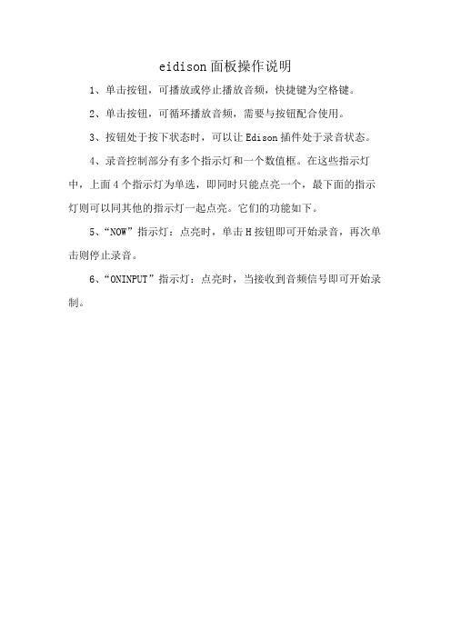
1、单击按钮,可播放或停止播放音频,快捷键为空格键。
2、单击按钮,可循环播放音频,需要与按钮配合使用。
3、按钮处于按下状态时,可以让Edison插件处于录音状态。
4、录音控制部分有多个指示灯和一个数值框。
在这些指示灯中,上面4个指示灯为单选,即同时只能点亮一个,最下面的指示灯则可以同其他的指示灯一起点亮。
它们的功能如下。
5、“NOW”指示灯:点亮时,单击H按钮即可开始录音,再次单击则停止录音。
6、“ONINPUT”指示灯:点亮时,当接收到音频信号即可开始录制。
(完整版)索图彩超工作站用户手册单机通用版(新版软件)

3.2.2.12.3备份为WORD………………………………………………………………………51
3.2.2.12.4备份为图片报告…………………………………………………………………52
3.2.2.13采集图像………………………………………………………………………………………52
3.2.2.11.5常见词库…………………………………………………………………………40
3.2.2.11.6测值管理…………………………………………………………………………41
3.2.2.11.7串口设置…………………………………………………………………………43
3.2.2.11.8最小化……………………………………………………………………………43
3.2.2.11.1用户管理…………………………………………………………………………29
3.2.2.11.2修改密码…………………………………………………………………………30
3.2.2.11.3设计报表…………………………………………………………………………30
3.2.2.11.4模板工具…………………………………………………………………………37
3.2.2.10.2设置通道…………………………………………………………………………25
3.2.2.10.3视频颜色…………………………………………………………………………26
3.2.2.10.4设置压缩格式……………………………………………………………………26
3.2.2.10.5设置图片输出大小………………………………………………………………26
3.2.2.4保存信息………………………………………………………………………………………19
安 friendship 医疗气体接叉 британ式窄型兼容模式指南说明书

Installation and Maintenance Manual Medical Gas OutletBritish Standard Slim Style Compatible0123ContentsProduct Description 3 Cleaning and Lubricating 3 Inspection and Testing 4 Installation and Dimensions 4-6 Console Mounted 5 Surface Mounted 6 Preventive Maintenance 7 Monthly 7 Annually 7 Gas Latch Valve Assembly 8 Vacuum Latch Valve Assembly 9 AGSS Latch Valve Assembly 10 Disassembly of the Check Valve Body Assembly 10 Reassembly of the Check Valve Body Assembly 10 AGSS Flow Control Adjustment 11 Reference Part Numbers 11 Rough-in Assembly 12 Removal of Internal Components 12 Reinstallation of Internal Components 12 Model Numbers 13 Console Mounted 13 Surface Mounted 13 Gas Indexing 14 Replacement Components 15-17 Gas and Vacuum Replacement Components 15 AGSS Replacement Components 16 Rough-In Assembly 172Amico Mobility Solutions CorporationProduct DescriptionThe Amico Medical Gas British Outlet Slim Style is composed of two separate modules: the “Rough-in Assembly”and the “Latch Valve Assembly”. The “Rough-in Assembly” consists of a brass machined body that incorporates a spring loaded check assembly except for Vacuum and AGSS. The copper pipe is SILVER brazed into the body and flared to 12 mm inside diameter for external pipeline connections. The brass body and pipe assembly are inserted into a gas specific plate. The “Rough-in Assembly” has a colour coded label on the front plate and copper pipe, sothat the installer can easily identify the gas that the copper pipe should be connected to. The “Rough-in Assembly” incorporates a check valve that allows the “Latch Valve Assembly” to be removed for service, without requiring the pipeline to be shut down. Vacuum and AGSS rough-ins include a pressure plug for testing and servicing purposes. The “Rough-in Assembly” has a DUAL pin gas specific indexing arrangement to prevent the wrong “Latch Valve Assembly” from being plugged into the “Rough-in Assembly” (see page 17).The “Latch Valve Assembly” is manufactured with a gas specific housing which accepts, retains and releases the probe, indexed on the back side to match gas specific indexing of the “Rough-in Assembly”.CAUTION: DO NOT over tighten the Latch Valve mounting screws! Distortion of the Latch Valve can occur.Outlets are available for Oxygen, medical air, surgical air, nitrous oxide, medical vacuum and anesthetic gas scavenging system. These are designed in accordance with HTM 02-01 and ISO 9170.This device has been manufactured to conform to the standards, specifications and operating procedures stated in this manual when installed, inspected, operated, maintained, and serviced in accordance with these instructions.The user of the device shall have the sole responsibility for any malfunction which results from improper installation, use, maintenance, alteration or modification.W ARNING: Keep all components dry and clean during installation. DO NOT alter or modify this device or any of its components in any way. Store in normal working and environmental conditions. Adverse environmental conditions, harsh abrasives or chemicals will cause damage to the unit.Cleaning and LubricatingThe Amico British Slim Style Outlets are factory cleaned for Oxygen service. Exposed surfaces of the Outlet maybe cleaned with a mild detergent solution or wiped with a disinfectant commonly used in patient rooms, which is compatible with plastic, anodized aluminum and die cast zinc. Lubricate elastomer seals sparingly with a lubricant that is Oxygen compatible. DO NOT USE OIL. 3Inspection and TestingPressure drops across the Amico Medical Gas British Outlet Slim Style shall comply with ISO 9170 Standards.* Absolute pressureAGSS Requirements for flow and pressure drop across terminal units with probe inserted complies with ISO 9170Standards.The Amico British Slim Style Outlets meet and exceed the requirements at the time of manufacture. However piping source capacity, sizing and restrictions my prevent outlets form attaining these values.Installation and DimensionsThe Amico British Slim Style Outlet should be mounted at a height of between 900 mm and 1400 mm above finished floor level and not less than 200 mm from any obstruction.Where more than one Outlet unit is to be mounted in one location, these should be mounted at the following spacing:• Two Outlet units - 150 mm centres• Three or more Outlets units - 135 mm centresOutlet units mounted in a horizontal array shall be installed in the following sequence when viewed from the front, left to right:O₂; N₂O; 50% O₂ / 50% N₂O; Medical Air, Surgical Air, Vacuum; AGSSPlease refer to HTM 02-01CAUTION: DO NOT braze rough-ins with front latch installed. Must use wet rag when brazing since the heat could damage the secondary check valve, seal, and other installed components. Use only mild soap-basedsolution for leak testing.4Amico Mobility Solutions Corporation 5Console MountedInch[mm]6 Amico Mobility Solutions CorporationSurface MountedInch[mm]Preventative MaintenanceRegular inspection and maintenance of the Outlets will prolong its life and reduce the possibility of sudden, inconvenient component failures. The use of damaged probes or faulty equipment may require further maintenance.Outlets should be subjected to regular inspection and testing as follows:Monthlya. Visually inspect the Outlet for signs of damage.b. Check to see if the Front Latch Assembly (2nd Fix) operates smoothly with the gas specific probe.c. If there is any disagreement with the operation of the Front Latch Assembly (2nd Fix), remove the unit for closerinspection/repair/replacement if necessary.Annuallya. Remove Trim Plate and clean debris from the mounting box.b. Remove Front Latch Assembly (2nd Fix) and inspect the barrel for any damage.c. Inspect the Rough-in Assembly (1st Fix) for any damage. If damaged or leaking, replace components.d. Test Front Latch Assembly (2nd Fix) for correct operation (connection and disconnection of the probe) using ablank probe. 7Gas Latch Valve Assembly1. Unscrew the two Surface Box Cover screws (1), and remove the Surface Box Cover (2) for Surface Mount Outlets, orpry off Trim Ring (3) for Console Mount Outlets with a flat screw driver.2. Unscrew the two Retaining screws (5) until the Latch Valve Assembly (4) can be removed from the Outlet.3. Remove the two Retaining washer screws (11), and remove the Retaining washer (10).4. Remove the Gas Connector (8).5. Remove the Body Seal (6), and the Poppet O-Ring (9), then the Poppet (7) from the front of the Gas Connector (8).Inspect the items for wear or damage and replace if needed.6. Re-install all internal components into the Gas Connector (8). Check that the Poppet (7), Poppet O-Ring (9), andBody Seal (6) are in place. Re-install the round Retaining washer (10) and secure with two Retaining washer screws(11), do not over tighten.7. Re-install the Latch Valve Assembly into the outlet. Coat the Gas Connector (8) with a thin coat of Oxygencompatible lubricant to aid insertion. Tighten down the Retaining screws (5), DO NOT over tighten, as this could damage the Latch Valve Assembly.8. Re-install Surface Box Cover (2), install Surface Box screws (1) and tighten down (DO NOT OVER TIGHTEN) or re-install Trim Ring (3).9. Connect gas specific adapter into the outlet. The connection should be smooth and the adapter should lock andremain in place allowing gas to flow. If not, replace the entire Latch Valve Assembly (4).8Amico Mobility Solutions CorporationNOTE:removing the Latch Valve Assembly.1. Unscrew the two Surface Box Cover screws (1), and remove the Surface Box Cover (2), for Surface Mount Outlets orpry off Trim Ring (3) for Console Mount Outlets with a flat screw driver.2. Unscrew the two Retaining screws (5) until the Latch Valve Assembly (4) can be removed from the Outlet.3. Remove the Primary Vacuum Spring (12) and inspect for damage, replace if needed.4. Remove the two Retaining washer screws (11), and remove the Retaining washer (10).5. Remove the Gas Connector (8).6. Remove the Body Seal (6), and the Poppet O-Ring (9), then the Poppet (7) from the front of the Gas Connector (8).Inspect the items for wear or damage and replace if needed.7. Re-install all internal components into the Gas Connector (8). Check that the Poppet (7), Poppet O-Ring (9), andBody Seal (6) are in place. Re-install the round Retaining washer (10) and secure with two Retaining washer screws(11), do not over tighten.8. Re-install the Primary Vacuum Spring (12).9. Re-install the Latch Valve Assembly into the outlet. Coat the Gas Connector (8) with a thin coat of Oxygencompatible lubricant to aid insertion. Tighten down the Retaining screws (5), DO NOT over tighten, as this could damage the Latch Valve Assembly.10. Re-install Surface Box Cover (2), install Surface Box screws (1) and tighten down (DO NOT OVER TIGHTEN) or re-install Trim Ring (3).11. Connect gas specific adapter into the outlet. The connection should be smooth and the adapter should lock andremain in place allowing gas to flow. If not, replace the entire Latch Valve Assembly (4). 91. Unscrew the two Surface box Cover screws (1), and remove the Surface Box Cover (2), for Surface Mount Outlets orpry off Trim ring (3) for Console Mount Outlets with a flat screw driver.2. Unscrew the two Retaining screws (5) until the “Latch Valve Assembly” (4) can be removed from the Outlet.3. After removing the “Latch Valve Assembly” (4) from the Outlet, you can then pull the Check Valve Body Assemblyfrom the back side of the “Latch Valve Assembly” (4). Remove the Check Valve Body Seals (10 & 11) and check for any abnormal wear or damage and replace if needed. Coat the O-Ring with a thin coat of Oxygen compatible lubricant.4. Disassembly of the Check Valve Body AssemblyHold the Check Valve Assembly in one hand, and push down the Check Valve (6) with your thumb of the same hand, compressing the Check Valve Spring (9). Remove the Check Valve O-Ring (13). Release the Check Valve (6) slowly; The Check Valve Body Assembly will fall apart. Inspect parts for abnormal damage or wear and replace if needed.5. Reassembly of the Check Valve Body AssemblyRe-install the Check Valve Spring (9) onto the Check Valve (6), and then insert them into the Check Valve Body (12).Again, hold the Check Valve Body Assembly in one hand, and push down the Check Valve (6) with your thumb of the same hand, compressing the Check Valve Spring (9). Before re-installing the Check Valve O-Ring (13), coat the O-Ring with a thin coat of Oxygen compatible lubricant.6. Insert the Check Valve Body Assembly into the back of the “Latch Valve Assembly”.7. Re-install the “Latch Valve Assembly” into the outlet. Coat the outer portion of the Check Valve Body Assemblywith a thin coat of Oxygen compatible lubricant, to aid insertion. Tighten down Retaining Screws (5). DO NOT over tighten, as this could damage the Latch Valve.8. Re-install Surface Box Cover (2), install Surface Box screws (1) and tighten down (DO NOT OVER TIGHTEN) or re-install Trim Ring (3).9. Connect gas specific adapter into the outlet. The connection should be smooth and the adapter should remain inplace allowing gas to flow. If not, replace the entire Latch Valve Assembly (4).10Amico Mobility Solutions Corporation 11AGSS Flow Control Adjustment1. Insert a 3 mm Allen key into the front of the Check Valve.2. Adjust the Flow Control Screw to desired setting.Reference Part Numbers O-BSQ-CON-AGS O-BSQ-SUR-AGSA.G.S.S.Threaded Nose British Standard A.G.S.S.A.G.S.S.THREADED NOSEBritish Standard A.G.S.S.Rough-in AssemblyInside the “Rough-in Assembly” is a secondary check valve whose function is to shut off gas flow when the “Latch Valve Assembly “ is removed. This seal O-Ring also prevents leakage around the Latch Valve connector. As the secondary seal is only a static seal, it will rarely need replacement. However, if the seal O-Ring does need replacement, follow the following procedure:NOTE:Suction inlets (Vacuum and AGSS) are not supplied with Secondary Check Valve. The Secondary Check Valve (2) and Secondary Check Valve Spring (3) are not required.1. Ensure that no pressure exists in the line by depressing the secondary check (2).2. Removal of Internal ComponentsDepress the Secondary Check Valve (2), with a dull screw driver (prevents damage on the Check Valve), at the same time pry out the Secondary Seal O-Ring (1), with a small screw driver. After the Secondary Seal O-Ring (1) is out.The Secondary Check Valve (2) and Secondary Check Valve Spring (3) are no longer locked in place and can be easily removed. Inspect all components for abnormal wear and replace.3. Reinstallation of Internal ComponentsInstall the Secondary Check Valve Spring (3) to the back side for the Secondary Check Valve (2). Then insert into the Rough-in Body (4). Insert Secondary Seal O-Ring (1), while depressing the Secondary Check Valve (2).4. Turn on the pressure and check for leaks. Re-install the “Latch Valve Assembly” and perform inspection and test.12Amico Mobility Solutions CorporationModel Numbers 13Gas IndexingAs seen from the front of the“Rough-in Assemblies”14Amico Mobility Solutions CorporationAbove parts with an * are found in repair kit: O-RK-LVA-BSQ, not sold individually. 15AGSS Replacement ComponentsAbove parts with an * are found in repair kit: O-RK-LVA-BSQSL-AGS, not sold individually. 16Amico Mobility Solutions Corporation 17Rough-in AssemblyNOTE:Suction inlets (Vacuum and AGSS) are not supplied with Secondary Check Valves. The Secondary Check Valve (2) andSecondary Check Valve Spring (3) are not required.Above parts with an * are found in repair kit: O-RK-BAK-BSQSL, not sold individually.Authorized Representative:AJW Technology Consulting GmbHKönigsallee 10640215 DüsseldorfTel: +49 (0) 211 3013 2232Amico Mobility Solutions Corporation122-B East Beaver Creek Road, Richmond Hill, ON L4B 1G6, Canada 600 Prime Place, Hauppauge, NY 11788, USAToll Free Telephone: 1.877.462.6426 | Telephone: 905.764.0800 | Fax: 905.764.0862 Email:**************|ACP-IM-MEDICAL-GAS-OUTLETS-BRITISH-STANDARD-SLIM 07.12.2022。
Anusplin使用方法(以降水数据为例)
Anusplin使用方法(以降水数据为例)anusplin气象插值软件,降水数据空间插值Anusplin 使用方法一、解压安装包可见anusplin 核心模块如下:我们主要用到的是splina 和lapgrd 程序,具体模块介绍和流程图可查询用户手册二、准备数据格式2.1 气象台站数据原始数据格式是以站点名、日期、气温、降水等变量为列,不便插值处理。
利用spss 转化为气象变量固定的文件,每个气象文件中均以站点和日期为列,变量唯一。
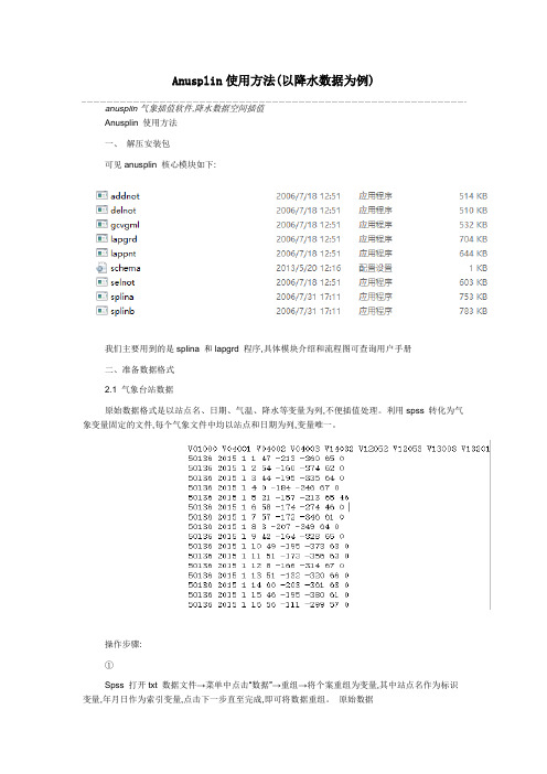
操作步骤:①Spss 打开txt 数据文件→菜单中点击“数据”→重组→将个案重组为变量,其中站点名作为标识变量,年月日作为索引变量,点击下一步直至完成,即可将数据重组。
原始数据整理数据注:数据不含表头,从第一行起就必须与下面的splina cmd 文件中的format 吻合②Spss打开txt站点信息文件(包含站点经纬度和高程)→在步骤①中的数据文件界面,菜单中点击“数据”→合并文件、添加变量→选择刚刚打开的站点信息文件→勾选匹配关键变量的个案,将站点名作为关键变量,活动集为基于变量的表,确定。
即可完成按照站点名进行站点信息的匹配和添加。
③将已包含了经纬高程信息的站点数据另存为固定的ASCII格式.dat,注意不是制表符分隔的.dat。
可供splina读取。
2.2 DEM数据下载STRM90m分辨率的原始高程数据(未经投影),在ArcGIS中对DEM文件进行镶嵌、投影(根据研究情况与其他数据统一投影即可)、重采样,最终利用toolbox中Conversion工具→From Raster to ASCII,转化为txt文本文件,可供lapgrd读取。
三、编写命令行3.1 Splina cmd在写字板中编辑,另存为.cmd后缀即可,以下是文件和说明:输出表面名要插数据的单位(由于是降水数据已处理为m,选择1)独立变量个数3(经度、纬度、高程)协变量个数0表面样条变量个数表面协变量个数经度的左右极限、是否转换(0-不转换)、单位(1-m)纬度的左右极限、是否转换(0-不转换)、单位(1-m)高程的上下限、是否转换(1-转换方式为x/a)、单位(1-m)转换系数a= 1000独立变量转换(2-将所有表面值调整为原来的平方根)样条次数(2次样条)输出表面个数,365个0-为每个表面采用同样权重1-优化参数,通常为1平滑参数选择方法(1-GCV法)输入数据文件.dat站点个数,设置得大一些站点标识符个数,5个字符输入数据格式,与spss中数据宽度和小数位一致。
苏普罗全解延时器用户指南说明书

User’s GuideThe Supro Delay is an all-analog pedal that can be tailored to suit a myriad of musical situations while being manipulated in real-time with an assignable expression pedal option.The TIME control sets the length of the echo. At minimum, the delay time is 20ms. At maximum, the delay time is 600ms.The LEVEL control sets the volume of the echo. At minimum, there is no echo, at maximum, the echo is louder than the original signal.The REPEATS control sets the amount of feedback sent from the output of the delay line back into the input of the delay line. At minimum, the is no feedback. In this setting, a single echo will be heard. At maximum the echo signal will regenerate to the point of self-oscillation, creating a resonant “runaway” delay.The FILTER control sets the frequency response of the echo. At minimum, the filter control provides an overall Low Pass (LPF) effect. This produces a darker sounding echo, with lesstreble. At maximum, the filter control provides an overall Band Pass (BPF) effect, rolling off both lows and highs to create a “tape echo” effect. The EXPRESSION mini toggle switch selects which knob function is controlled by the expression pedal. In the UP position, LEVEL is selected. In the MIDDLE position, TIME is selected. In the DOWN position, REPEATS is selected.The EXPRESSION jack accepts a 1/4” TRS cable from a standard expression pedal. The expression pedal can be assigned to control either LEVEL, TIME or REPEATS functions. The position of the on-board knob corresponding to the currently selected expression pedal assignment will set the maximum range of the expression pedal.POWER: The Supro delay runs on standard 9VDC (neg. tip) power only, using internal voltage-doubling to provide the necessary headroom for world-class performance in an all-analog Stompbox. The Supro Delay does not run on batteries.DRIVEThis groundbreaking analog pedal re-creates the circuitry of a Supro amp from end to end, including a preamp, phase inverter, and an actualoutput transformer.TREMOLOThe Supro Tremolo is designed to recreate two of the most desirable vacuum tube based modulation effects found inAmerican amplifiers of the 1960’s.The Supro Delay is a premium analog echo pedal that delivers up to 600ms of buttery vintage delay. In addition to TIME, REPEATS and LEVEL knobs, the Supro Delay features a unique FILTER control that provides both low-pass and band-pass functions on a single knob. Using a pair of new-production, MN3005 “bucket brigade” IC chips, the Supro Delay achieves the best signal-to-noise ratio and the most headroom available from any analog echo pedal, new or vintage.Housed in a custom-made anodized alumi-num chassis, the Supro Delay features soft-touch, click-free true bypass switching, so no footswitch noise creeps into your delay line. The Supro delay runs on standard 9VDC pow-er, using internal voltage-doubling to provide world-class performance from a compact stompbox. Taking the analog delay pedal platform one step further, Supro Delay offers an Expression port for assignable control of the TIME, REPEATS or LEVEL knobs using a standard TRS expression pedal.Supro Limited Warranty:Your Supro effect pedal comes with a 1 year limited warranty on parts and workmanship. During the warranty period we will repair or replace, at our option, defective parts or pedals free of charge, and return them to the owner.Warranty service does not include damaged, mod-ified, or misused pedals and such pedals will be subject to a standard repair charge.What you must do: First, contact us directly via email and describe the problem to us. If the problem cannot be resolved we will have you send the pedal directly to us for servicing.How to contact us for warranty service: Email: *****************Phone: 631-331-7447Warranty Limitations: This warranty does not cover defects resulting from improper or unreasonable use, accident,unauthorized tampering or modifications; and, warranty shall be considered void if chassis has been opened.To validate your 1-year, limited warranty, please register your Supro pedal, within 30 days of pur-chase,on the web at: /warrantyTMAbsara Audio LLC200 Wilson St. Bldg F Port Jeff Station, NY 11776 Phone: 631-331-7447 ***************** All contents © 2018 Absara Audio LLC。
小熊派硬件使用指导手册

首页-技术文档小熊派硬件使用指导手册Revision 1.0 2019 年 4 月 8 日小熊派硬件使用指导手册目录首页-技术文档 ....................................................... 11. 概述31.1. 工具包概述 31.2. 系统要求31.3. 开发工具32. 小熊派主板 ...................................................... 42.1. 特性42.2. 开发板硬件信息 ............................. 错误!未定义书签。
2.3. 开发板框架 52.4. MCU 主板外设接口介绍...................................... 63. 程序下载 104. Pinout Configurations ........................................................................................... 115. Pinout Configurations ........................................................................................... 126. Clock Tree Configuration ....................................................................................... 14小熊派硬件使用指导手册1. 概述1.1. 工具包概述这是一款由南京小熊派智能科技有限公司联合华为技术有限公司基于 STM32L431RCT6 设计的高性能物联网开发板。
开发板充分考虑物联网感知层设备 的多样性,具有强大的可扩展性,用于提供给开发者评估及快速设计相关物联网的 应用产品。
- 1、下载文档前请自行甄别文档内容的完整性,平台不提供额外的编辑、内容补充、找答案等附加服务。
- 2、"仅部分预览"的文档,不可在线预览部分如存在完整性等问题,可反馈申请退款(可完整预览的文档不适用该条件!)。
- 3、如文档侵犯您的权益,请联系客服反馈,我们会尽快为您处理(人工客服工作时间:9:00-18:30)。
ANUSPLIN操作说明书
ANUSPLIN作为一个气象插值软件,网上有很多人找我问这些问题。
该软件与传统的界面式操作软件不同,所以刚开始接触的时候很多人感觉束手无策。
在此我写个说明文档,希望对刚开始接触学习的人有所帮助!如果仍有问题欢迎加QQ群466083085 进行交流。
数据的准备工作就不多了,气象数据利用SPSS整理成固定ASCII格式,栅格数据在arcgis下面转换为ASCII格式。
具体操作可百度。
因个人水平有限,文档中有什么错误望指正!
数据不论是地理坐标还是投影坐标都能运行,但是你的实验需要什么数据类型自行决定!
软件的使用主要是调用splina.exe和lapgrd.exe两个程序。
接下来我先介绍splina的脚本如何编写
这是一个完整的cmd文件示例。
下面我来解释一下每一行都代表什么东西。
图中可能说的不是很清楚,1000就是转换数据的转换系数
后面还有验证文件输入名称,一般情况没有验证文件可以添加空格行保存后就可使用。
接下来我说说lapgrd的脚本编写,下面是一个输出单个表面的完整脚本样例
下面是一个输出三个表面的脚本样例
接下来解释一下每个参数的意义
在做实验的时候必须注意的问题是splina的范围一定要比lapgrd的范围略大
原因在与栅格数据和矢量数据不能完全吻合,会产生误差,第一个命令设定好的范围栅格数据不能确保在范围之内执行命令就会报错。
软件运行其实很简单,你只要写好cmd脚本文件就可以调用你的软件了。
Win+R键打开运行输入cmd 即可打开命令提示符窗口
这其实是个DOS界面,首先你要进入你cmd文件、数据文件、exe程序的路径。
如图所示,我进入了文件的所在路径。
然后输入splina<气温.cmd>temp.log 后按回车即可运行splina.exe程序。
splina代表你的splina.exe程序
气温.cmd代表写的cmd脚本名称
temp.log是日志文件,你在哪出错了或者你每一步输入的命令是做什么的你都可以在这里面进行查看。
同理lapgrd也是一样的。
